EP3971640B1 - Gehäuse einer bilderfassungsvorrichtung - Google Patents
Gehäuse einer bilderfassungsvorrichtung Download PDFInfo
- Publication number
- EP3971640B1 EP3971640B1 EP21196118.0A EP21196118A EP3971640B1 EP 3971640 B1 EP3971640 B1 EP 3971640B1 EP 21196118 A EP21196118 A EP 21196118A EP 3971640 B1 EP3971640 B1 EP 3971640B1
- Authority
- EP
- European Patent Office
- Prior art keywords
- lens
- housing
- edge
- lens barrel
- channel
- Prior art date
- Legal status (The legal status is an assumption and is not a legal conclusion. Google has not performed a legal analysis and makes no representation as to the accuracy of the status listed.)
- Active
Links
Images


Classifications
-
- G—PHYSICS
- G03—PHOTOGRAPHY; CINEMATOGRAPHY; ANALOGOUS TECHNIQUES USING WAVES OTHER THAN OPTICAL WAVES; ELECTROGRAPHY; HOLOGRAPHY
- G03B—APPARATUS OR ARRANGEMENTS FOR TAKING PHOTOGRAPHS OR FOR PROJECTING OR VIEWING THEM; APPARATUS OR ARRANGEMENTS EMPLOYING ANALOGOUS TECHNIQUES USING WAVES OTHER THAN OPTICAL WAVES; ACCESSORIES THEREFOR
- G03B17/00—Details of cameras or camera bodies; Accessories therefor
- G03B17/02—Bodies
-
- G—PHYSICS
- G02—OPTICS
- G02B—OPTICAL ELEMENTS, SYSTEMS OR APPARATUS
- G02B7/00—Mountings, adjusting means, or light-tight connections, for optical elements
- G02B7/02—Mountings, adjusting means, or light-tight connections, for optical elements for lenses
- G02B7/025—Mountings, adjusting means, or light-tight connections, for optical elements for lenses using glue
-
- G—PHYSICS
- G02—OPTICS
- G02B—OPTICAL ELEMENTS, SYSTEMS OR APPARATUS
- G02B7/00—Mountings, adjusting means, or light-tight connections, for optical elements
- G02B7/02—Mountings, adjusting means, or light-tight connections, for optical elements for lenses
- G02B7/04—Mountings, adjusting means, or light-tight connections, for optical elements for lenses with mechanism for focusing or varying magnification
-
- G—PHYSICS
- G03—PHOTOGRAPHY; CINEMATOGRAPHY; ANALOGOUS TECHNIQUES USING WAVES OTHER THAN OPTICAL WAVES; ELECTROGRAPHY; HOLOGRAPHY
- G03B—APPARATUS OR ARRANGEMENTS FOR TAKING PHOTOGRAPHS OR FOR PROJECTING OR VIEWING THEM; APPARATUS OR ARRANGEMENTS EMPLOYING ANALOGOUS TECHNIQUES USING WAVES OTHER THAN OPTICAL WAVES; ACCESSORIES THEREFOR
- G03B17/00—Details of cameras or camera bodies; Accessories therefor
- G03B17/02—Bodies
- G03B17/12—Bodies with means for supporting objectives, supplementary lenses, filters, masks, or turrets
-
- H—ELECTRICITY
- H04—ELECTRIC COMMUNICATION TECHNIQUE
- H04N—PICTORIAL COMMUNICATION, e.g. TELEVISION
- H04N23/00—Cameras or camera modules comprising electronic image sensors; Control thereof
- H04N23/50—Constructional details
- H04N23/51—Housings
-
- H—ELECTRICITY
- H04—ELECTRIC COMMUNICATION TECHNIQUE
- H04N—PICTORIAL COMMUNICATION, e.g. TELEVISION
- H04N23/00—Cameras or camera modules comprising electronic image sensors; Control thereof
- H04N23/50—Constructional details
- H04N23/54—Mounting of pick-up tubes, electronic image sensors, deviation or focusing coils
-
- H—ELECTRICITY
- H04—ELECTRIC COMMUNICATION TECHNIQUE
- H04N—PICTORIAL COMMUNICATION, e.g. TELEVISION
- H04N23/00—Cameras or camera modules comprising electronic image sensors; Control thereof
- H04N23/50—Constructional details
- H04N23/55—Optical parts specially adapted for electronic image sensors; Mounting thereof
Definitions
- Exemplary embodiments of the present disclosure relate generally to an image capturing device and, more particularly, to a housing of an imaging unit in the image capturing device.
- image capturing devices such as but not limited to, cameras, barcode scanners, and imagers, include an imaging unit that is configured to capture images of an object.
- the imaging unit further includes a housing, an image sensor and a lens barrel.
- the housing may be configured to receive the image sensor and the lens barrel in such a manner that ambient light passes through the lens barrel and is focused on the image sensor.
- the lens barrel and the image sensor need to be aligned with each other.
- US 2020/124818 A1 discloses an interlock arrangement that may be used to attach a lens barrel to a lens carrier of a camera.
- the interlock arrangement may restrict movement of the lens barrel relative to the lens carrier along at least an optical axis.
- the interlock arrangement may include one or more grooves and one or more protrusions.
- a groove may be defined by the lens barrel or the lens carrier, and a protrusion may extend from the lens barrel or the lens carrier to at least partially into the groove.
- the interlock arrangement may include an adhesive that at least partially fills gaps within the interlock arrangement between the lens barrel and the lens carrier.
- the interlock arrangement may include one or more recesses that provide inlets for the adhesive to be introduced to the gaps within the interlock arrangement.
- US 10663714 B2 discloses a lens assembly of a viewing element for an endoscope that has lenses and a barrel containing the lenses.
- the internal surface of the barrel is shaped in accordance with the relative position and size of the lenses and a lens holder encompassing at least a portion of the barrel.
- the barrel and/or the lens holder are injection-molded and can be variably positioned relative to each other.
- An optional adhesive layer that reduces or eliminates small particles from the viewing element is positioned on an inner surface of the barrel and/or lens holder and used to remove any internal particulate matter that may otherwise obstruct the field of view.
- AU 2019283800 B2 discloses an imaging device including a housing having a surface that can engage the face of a patient. A cavity is at least partially defined by the surface.
- An anterior imaging system includes an optical lens barrel positioned inside the cavity, and the optical lens barrel includes a variable focus lens at one end and an image sensor array at an opposite end.
- One or more illumination LEDs are positioned around the periphery of the optical lens barrel at opposite sides of the variable focus lens, and are configured to illuminate the cavity to capture images of an anterior of the eye.
- the image capturing device comprises an imaging unit that further includes a housing that comprises an inner surface.
- the inner surface of the housing defines a lens channel, wherein the inner surface of the lens channel defines a contact point that protrudes outwardly from the inner surface into the lens channel.
- Further inner surface defines a through hole, in the lens channel, which extends from the inner surface of the lens channel to an outer surface of the housing.
- the image capturing device further includes a lens barrel received in the lens channel, the lens barrel comprising an outer surface that defines a first portion, a first platform that circumferentially rotates about a first central longitudinal axis of the lens barrel, wherein a first step is defined at a junction between the first platform and the first portion.
- the lens barrel further defines a groove defined on the first platform, wherein the groove circumferentially rotates about the first central longitudinal axis of the lens barrel, wherein when the first step abuts the contact point, the groove is exposed via the through hole.
- a housing of an imaging unit comprising an outer surface and an inner surface, wherein the inner surface of the housing defines a lens channel, wherein the inner surface of the lens channel defines a contact point that protrudes outwardly from the inner surface into the lens channel.
- the inner surface of the lens channel further defines a through hole, in the lens channel, that extends from the inner surface of the lens channel to the outer surface of the housing.
- the lens channel is configured to receive a lens barrel comprising a groove, wherein the groove is exposed to the through hole when the lens barrel is received in the lens channel.
- a lens barrel that includes a housing having an outer surface.
- the outer surface defines a first portion, and a first platform that circumferentially rotates about a first central longitudinal axis of the lens barrel, wherein a first step is defined at a junction between the first platform and the first portion.
- outer surface defines a groove defined on the first platform, wherein the groove circumferentially rotates about the first central longitudinal axis of the lens barrel.
- component or feature may,” “can,” “could,” “should,” “would,” “preferably,” “possibly,” “typically,” “optionally,” “for example,” “often,” or “might” (or other such language) be included or have a characteristic, that particular component or feature is not required to be included or to have the characteristic. Such component or feature may be optionally included in some embodiments, or it may be excluded.
- image sensor is referred to as a solid state device that is capable of generating electrical signals corresponding to the light signals that impinges on the image sensor.
- image sensor may include a color or monochrome 1D or 2D CCD, CMOS, NMOS, PMOS, CID CMD solid state image sensor or any other device, that may be capable to generating electrical signal based on the received light signals.
- the imaging unit may include a housing for one or more components such as one or more lenses (positioned in a lens barrel), an image sensor and a controller.
- the one or more components may operate in conjunction, to facilitate the image capturing device to capture and process an image of the object.
- the one or more lenses in the lens barrel may focus the light obtained from the object on the image sensor that, accordingly, generates electrical signals.
- the controller may, thereafter, process the electrical signals to render the captured image.
- an alignment between the lens barrel and the image sensor may govern the quality of the captured image. Misalignment between the lens barrel and the image sensor may lead to capturing of an out of focus image, which may be undesirable.
- the housing of the imaging unit may define features such as grooves or flanges that may ensure that the lens barrel and the image sensor are aligned with each other.
- adhesive may be applied between the lens barrel and the housing to keep the lens barrel fixed at a position within the housing, thereby aligning the lens barrel with the image sensor.
- curing of the adhesive causes the adhesive to shrink by few millimeters or micrometers. Such phenomena may modify the position of the lens barrel within the imaging unit, which may further lead to misalignment between the image sensor and the lens barrel.
- the apparatuses described herein disclose an image capturing device that includes an imaging unit.
- the imaging unit further includes a cuboidal shaped housing (hereinafter referred to as housing) having a first sensor end portion and a scan window end portion. Further, the housing has an outer surface and an inner surface. The inner surface of the housing defines at least one lens channel.
- the at least one lens channel has a cylindrical shape and extends from the first sensor end portion to the scan window end portion.
- the at least one lens channel is sized to receive a lens barrel.
- the at least one lens channel may be sized larger than lens barrel such that the lens barrel is seamlessly received in the at least one lens channel.
- the inner surface of the housing defines one or more contact points within the at least one lens channel.
- the one or more contact points protrude out from the inner surface.
- the one or more contact points thwart the movement of the lens barrel within the lens channel.
- the one or more contact points thwart the movement of the lens barrel along a first central longitudinal axis of the lens channel.
- the central longitudinal axis may correspond to an axis that extends along a length of the lens channel.
- the first central longitudinal axis may extend between the scan window end portion and first sensor end portion of the housing.
- the inner surface of the housing defines at least one glue pocket within the at least one lens channel.
- the at least one glue pocket extends from the inner surface of the housing to the outer surface of the housing.
- the at least one glue pocket corresponds to a through hole that extends from the inner surface of the housing to the outer surface of the housing. It is commonly understood that when a through hole is defined in a housing, one or more edge surfaces, defining a periphery of the through hole, are also created. Accordingly, a periphery of the at least one glue pocket may be defined by the one or more edge surfaces that may extend from the outer surface of the housing to the inner surface of the housing. In some examples, the one or more edge surfaces may define a shape of the at least one glue pocket.
- the at least one glue pocket may have an arcuate shape such that a first edge surface of the one or more edge surfaces is parallel to a second edge surface of the one or more edge surfaces. Further a third edge surface and a fourth edge surface of the one or more edge surfaces may have a semi-circular profile. For example, the third edge surface and the fourth edge surface may be C-shaped profile.
- the inner surface of the housing defines the at least one glue pocket in such manner that the first edge surface (of the one or more edge surfaces defining the periphery of the at least one glue pocket) may be positioned proximal to the first sensor end portion of the housing, while the second edge surface (of the one or more edge surfaces defining the periphery of the at least one glue pocket) may be positioned proximal to the scan window end portion of the housing.
- the at least one glue pocket may be defined proximal to the scan window end portion of the housing such that the at least one glue pocket is defined between the scan end portion of the housing and the one or more contact points. Further, the one or more contact points are defined proximal to the first sensor end portion such that the one or more contact points are defined between the glue pocket and the first sensor end portion of the housing.
- the at least one lens channel is configured to receive the lens barrel from the scan window end portion.
- the lens barrel corresponds to lens housing for one or more lenses.
- the one or more lenses may be configured to focus the light received from the object onto an image sensor positioned at the first sensor end portion of the housing.
- the lens barrel has a sensor end, a light receiving end, and an outer surface that extends between the sensor end of the lens barrel and the light receiving end of the lens barrel.
- the outer surface of the lens barrel defines a platform and a second sensor end portion.
- the platform protrudes out from the outer surface of the lens barrel and may circumferentially rotate about a second longitudinal central axis of the lens barrel.
- the second longitudinal central axis may correspond to an axis that extends between the sensor end and the light receiving end of the lens barrel.
- the platform may extend from the light receiving end to a junction between the platform and the second sensor end portion of the lens barrel.
- a radius of the platform is greater than a radius of the second sensor end portion.
- a step is defined at the junction between the first sensor end portion and the platform.
- the step may have a predetermined pitch and a predetermined profile.
- the predetermined pitch may correspond to an angle between the step and a lateral axis of the lens barrel.
- the predetermined profile may be indicative of a shape of the step as the step rotates about of the second central longitudinal axis.
- the predetermined profile of the step may correspond to a shape of a sinusoidal wave.
- the one or more contact points when the lens barrel is received in the lens channel, the one or more contact points (defined in lens channel) may abut step, thereby thwarting the movement of the lens barrel along the first central longitudinal axis of the lens channel.
- the platform may define a groove that may circumferentially rotate about the second central longitudinal axis of the lens barrel.
- the groove may correspond to a recess defined on the platform of the lens barrel.
- the groove may have the same predetermined pitch as the pitch of the step.
- the groove may the same predetermined profile as the profile of the step.
- a portion of the groove may be exposed via the glue pocket. Since the predetermined profile of the groove is the same as the predetermined profile of the step, when the lens barrel is rotated within the lens channel while the one or more contact points abut the step, the portion of the groove (defined on the lens barrel) remains exposed through the glue pocket.
- the adhesive When glue is disposed on the groove through the glue pocket, the adhesive may get evenly distributed within the groove because the groove (defined on the lens barrel) has a fixed profile and the groove is exposed through the glue pocket. Accordingly, variations due to curing of the glue (e.g., movement of the lens barrel within lens channel due to curing of the glue) remain consistent during manufacturing of various imaging units. Therefore, any anticipated change in the focal point of the lens barrel (due to glue curing) can be compensated prior to the glue curing consistently across various imaging unit.
- FIG. 1 illustrates a perspective view 100 of an image capturing device 102, according to one or more embodiments described herein.
- the image capturing device 102 may correspond to a barcode scanner that may be capable of scanning and reading machine readable codes such as a barcode, a QR code, 2D code, Datamatrix code, and/or the like.
- the image capturing device 102 may be further capable of reading and recognizing text from an image, without departing from the scope of the disclosure.
- the image capturing device 102 may include a head portion 104, a handle portion 106, and a trigger button 108.
- the head portion 104 may have an arcuate shape that has a scan window end 110 and a rear end 112.
- the scan window end 110 and the rear end 112 of the head portion 104 may be spaced apart from each other along a first lateral axis 118.
- the head portion 104 may define a scan window 114, at the scan window end 110 of the head portion 104.
- the scan window 114 may be configured to receive an imaging unit 116.
- the imaging unit 116 may include one or more components (e.g., processors, lenses, illumination devices, cameras, and/or the like) for performing scanning operations.
- the structure of the imaging unit 116 is further described in conjunction with FIGS. 2-6 .
- the handle portion 106 may extend out from the head portion 104 along a first longitudinal axis 120 of the image capturing device 102.
- the trigger button 108 may be positioned on the handle portion 106. In some examples, the trigger button 108 may be positioned on the head portion 104, without departing from the scope of the disclosure.
- a user of the image capturing device 102 may point the image capturing device 102 in the direction of a target object such that the scan window end 110 is pointed towards the target object.
- the user may input a command (e.g., via the trigger button 108) and cause the imaging unit 116 to scan the target object.
- the information gathered by the imaging unit 116 may be transmitted a host (not shown) over a communication network (not shown).
- FIG. 2 and FIG. 3 illustrate a perspective view 200 and an exploded view 300 of the imaging unit 116, respectively, according to one or more embodiments described herein.
- the imaging unit 116 includes a housing 202, a lens barrel 204, an illumination lens 206, an aiming lens assembly 208, and an image sensor 209.
- the housing 202 of the imaging unit 116 corresponds to a cuboidal housing that includes a scan window end portion 210 and a first sensor end portion 212.
- the scan window end portion 210 may be spaced apart from the first sensor end portion 212 along a second lateral axis 214.
- the first sensor end portion 212 of the housing 202 may be configured to fixedly receive the image sensor 209.
- the scan window end portion 210 of the housing 202 may be configured to be pointed towards the scan window end 110 of the head portion 104, in an instance in which the imaging unit 116 is received in the head portion 104 of the image capturing device 102.
- the housing 202 of the imaging unit 116 has a top portion 216, a bottom portion 218, a first side portion 220, and a second side portion 222.
- the bottom portion 218 is parallel to the top portion 216.
- the bottom portion 218 and the top portion 216 are spaced apart from each other along a vertical axis 224.
- the first side portion 220 is parallel to the second side portion 222.
- the first side portion 220 and the second side portion 222 are spaced apart along a second longitudinal axis 226.
- the second lateral axis 214, the vertical axis 224, and the second longitudinal axis 226 are perpendicular to each other.
- the top portion 216 of the housing 202 has a top surface 228, while the bottom portion 218 has a bottom surface 230.
- the first side portion 220 and the second side portion 222 has a first side surface 232 and a second side surface 234, respectively.
- the top surface 228 of the top portion 216 may define a first edge 223 and a second edge 221.
- the first edge 223 may be defined at the scan window end portion 210, while the second edge 221 may be defined at the first sensor end portion 212.
- the first edge 223 may be parallel to the second edge 221.
- the housing 202 of the imaging unit 116 has an inner surface 238.
- the inner surface 238 of the housing 202 defines a lens channel 302 such that the lens channel 302 is positioned proximal to the first side portion 220 of the housing 202 and distal from the second side portion 222 of the housing 202.
- the lens channel 302 may extend between the scan window end portion 210 and the first sensor end portion 212, of the housing 202.
- the lens channel 302 may have a cylindrical shape.
- the lens channel 302 is sized to receive the lens barrel 204. For example, a radius of the lens channel 302 may be greater than the radius of the lens barrel 204 allowing the lens barrel 204 to be received within the lens channel 302.
- the inner surface 238 of the housing 202 defines a glue pocket 304 in the lens channel 302.
- the glue pocket 304 corresponds to a through hole that extends from the inner surface 238 of the housing 202 to the outer surface 236 of the housing 202.
- the glue pocket 304 extends from the inner surface 238 of the housing 202 to the top surface 228 (that constitutes the outer surface 236) of the housing 202.
- defining a glue pocket creates one or more edge surfaces in the housing 202 that may define a periphery of the glue pocket 304.
- the one or more edge surfaces may extend from the inner surface 238 of the housing 202 to the outer surface 236 of the housing 202.
- the one or more edge surfaces (defining the periphery of the glue pocket 304) includes a first edge surface 312, a second edge surface 314, a third edge surface 316, and a fourth edge surface 318.
- the first edge surface 312 of the one or more edge surfaces may be proximate to the first sensor end portion 212 of the housing 202, while the second edge surface 314 of the one or more edge surfaces (defining the periphery of the glue pocket 304) may be proximate to the scan window end portion 210 of the housing 202.
- the first edge surface 312 of the one or more edge surfaces is parallel to the second edge surface 314 of the one or more edge surfaces (defining the periphery of the glue pocket 304).
- the first edge surface 312 of the one or more edge surfaces is spaced apart from the second edge surface 314 along the second lateral axis 214 of the housing 202.
- the scope of the disclosure is not limited to the second edge surface 314 being parallel to the first edge surface 312.
- the first edge surface 312 may not be parallel to the second edge surface 314, without departing from the scope of the disclosure. Additionally or alternatively, the first edge surface 312 and the second edge surface 314 may be parallel to the first edge 223 and the second edge 221 of the housing 202.
- the third edge surface 316 of the one or more edge surfaces may be parallel to the fourth edge surface 318. Further, the third edge surface 316 is spaced apart from the fourth edge surface 318 along the second longitudinal axis 226 of the housing 202. Furthermore, the third edge surface 316 may be proximal to the first side portion 220 of the housing 202, while the fourth edge surface 318 may be proximal to the second side portion 222 of the housing 202. In some examples, the scope of the disclosure is not limited to the third edge surface 316 being parallel to the fourth edge surface 318.
- the third edge surface 316 and the fourth edge surface 318 may have a C-shaped profile and inverted C-shaped profile, respectively. In some examples, the scope of the disclosure is not limited to the third edge surface 316 and the fourth edge surface 318 having the C-shaped profile and inverted C-shaped profile, respectively. In an example embodiment, the third edge surface 316 and the fourth edge surface 318 may have any other profile, without departing from the scope of the disclosure.
- the inner surface 238 defines one or more contact points (further described in FIG. 4A and FIG. 4B ) in the lens channel 302.
- the structure of the one or more contact points is further described in conjunction with FIG. 4A and FIG 4B .
- FIG. 4A and FIG 4B illustrates sectional views 400A and 400B, respectively, of the housing 202 obtained when the housing 202 is cut by a first plane 401 passing through the glue pocket 304 along the vertical axis 224, according to one or more embodiments described herein.
- the sectional view 400A of the housing 202 illustrates that the inner surface 238 of the housing 202 defines a first platform 402.
- the first platform 402 may protrude out from the inner surface 238 of the housing 202 within the lens channel 302.
- the first platform 402 rotates about a first central longitudinal axis 404 of the lens channel 302.
- the first platform 402 may divide the lens channel 302 into a lens receiving section 406 and a rear section 408.
- the lens receiving section 406 may correspond to a portion of the lens channel 302 that may be configured to receive the lens barrel 204 (refer FIG. 3 ). Additionally, the lens receiving section 406 may extend from the scan window end portion 210 to a junction 412 between the rear section 408 and the lens receiving section 406.
- the rear section 408 may correspond to portion of the lens channel 302 that may be proximal to the first sensor end portion 212 (refer FIG 4B ) of the housing 202. Further, the rear section 408 may extend from the junction 412 (between the rear section 408 to the lens receiving section 406) to the first sensor end portion 212 of the housing 202. Additionally, the rear section 408 may be composed of the first platform 402.
- a radius of the rear section 408 is less than a radius of the lens receiving section 406. Accordingly, a first step 410 is defined at the junction 412 between the rear section 408 and the lens receiving section 406, as is observed from the scan window end portion 210 of the housing 202. Additionally or alternately, the inner surface 238 of the housing 202 may define the one or more contact points 414a and 414b (refer FIG. 4B ). In an example embodiment, the one or more contact points 414a and 414b may extend out from the first step 410 in a direction towards the scan window end portion 210 of the housing 202 (i.e., along the first central longitudinal axis 404).
- the one or more contact points 414 a may protrude from the inner surface 238 of the housing 202.
- the contact point 414a may be positioned opposite to the contact point 414b along the vertical axis 224 of the housing 202.
- the contact point 414a may be defined proximal to the bottom portion 218 of the housing 202 and the contact point 414b may be defined proximal to the top portion 216 of the housing 202.
- the structure and the dimensions of the contact point 414a may be similar to the structure and the dimensions of the contact point 414b.
- the contact point 414a has a first end 416 and a second end 418.
- the first end 416 may be spaced apart from the second end 418 along the first central longitudinal axis 404.
- the second end 418 may be proximal to the scan window end portion of the 210 of the housing 202 and distal from the first sensor end portion 212 of the housing 202.
- the first end 416 of the contact point 414a may be coupled to the first platform 402.
- the first end 416 may be molded with the first platform 402 during manufacturing of the housing 202.
- the second end 418 of the contact point 414a may have a curved profile.
- the second end 418 of the contact point 414a may have a semi-circular profile.
- the second end 418 of the contact point 414a may have a conical profile.
- the second end 418 of the contact point 414a may have any other profile without departing from the scope of the disclosure.
- the purpose of the profile of the second end 418 (of the one or more contact points 414a and 414b) is further described in conjunction with FIGS. 6 .
- the second end 418 of the one or more contact points 414a and 414b may be defined at a first predetermined distance from the first edge surface 312 defining the periphery of the glue pocket 304.
- the scope of the disclosure is not limited to the one or more contact points 414a and 414b extending out from the first platform 402.
- the one or more contact points 414a and 414b may be defined independent from the first platform 402.
- the lens channel 302 may be devoid of the first platform 402, without departing from the scope of the disclosure.
- the scope of the disclosure is not limited to having only two contact points (i.e., 414a and 414b).
- the inner surface 238 of the housing 202 may define more than two contact points 414a and 414b.
- the inner surface 238 may define another contact point in the lens channel 302, where the other contact point is defined proximal to the first side portion 220 of the housing 202.
- the inner surface 238 may define yet another contact point in the lens channel 302 that is proximal to the second side portion 222 of the housing 202.
- the lens channel 302 may not include any of the one or more contact points 414a and 414b.
- the lens channel 302 may only include the first platform 402.
- the first step 410 (created due to difference in radius of the first platform 402 from the radius of the lens receiving section 406) may have a first predetermined profile.
- the first predetermined profile of the first step 410 may correspond to a shape of the first step 410, as the first step 410 rotates about the first central longitudinal axis 404.
- the first step 410 may have a shape representing a sinusoidal wave.
- the first predetermined profile of the first step 410 may have a peak region and a valley region.
- the first step 410 may have more than one peak regions and valley regions.
- the functionality of the peak region may be similar to the functionality of the one or more contact points 414a and 414b.
- the lens channel 302 is configured to receive the lens barrel 204.
- the structure the lens barrel 204 is further described in conjunction with FIG. 5A and FIG. 5B .
- FIG. 5A and FIG. 5B illustrate a perspective view 500A and a side view 500B of the lens barrel 204, respectively, according to one or more embodiments described herein.
- the lens barrel 204 includes a lens housing 502 that may be configured to receive a lens assembly (not shown).
- the lens housing 502 may correspond to a cylindrical housing that has a light receiving end 504 and a sensor end 506. Further, the lens housing 502 has an outer surface 508 that extends between the light receiving end 504 and the sensor end 506.
- the light receiving end 504 of the lens housing 502 may be configured to receive the light from the object to be captured by the imaging unit 116.
- the sensor end 506 of the lens housing 502 may face towards the image sensor 209 in the imaging unit 116 when the lens barrel 204 is received in the lens channel 302.
- the outer surface 508 of the lens housing 502 defines a platform 510 and a first portion 512.
- the platform 510 of the lens housing 502 may extend between the light receiving end 504 and a junction 516 between the platform 510 and the first portion 512.
- the platform 510 may be defined to circumferentially rotate about a second central longitudinal axis 520 of the lens housing 502.
- the second central longitudinal axis 520 may extend between the light receiving end 504 and the sensor end 506 of the lens housing 502.
- the first portion 512 may extend between the sensor end 506 of the lens housing 502 and the junction 516 between the platform 510 and the first portion 512 of the lens housing 502.
- the radius of the platform 510 is greater than the radius of the first portion 512 of the lens housing 502. Accordingly, a second step 518 is defined at the junction 516 between the platform 510 and the first portion 512 of the lens housing 502. Since the platform 510 is defined to rotate about the second central longitudinal axis 520, the second step 518 may rotate about of the second central longitudinal axis 520 of the lens housing 502. In an example embodiment, the second step 518 may have a second predetermined profile and/or a second predetermined pitch. In an example embodiment, the second predetermined pitch may correspond to an angle between the second step 518 and the second lateral axis 214 of the housing 202.
- the second predetermined profile of the second step 518 may correspond to a shape of the second step 518, as the second step 518 rotates about the second central longitudinal axis 520.
- the second step 518 may have a shape representing the sinusoidal wave.
- the second predetermined profile of the second step 518 may define a peak region 522 and a valley region 524 (refer FIG 5B ) on the second step 518 (as the second step 518 rotates about the second central longitudinal axis 520.
- the scope of the disclosure is not limited to the second predetermined profile of the second step 518 defining one peak region 522 and one valley region 524.
- the second predetermined profile of the second step 518 may define more than one peak region and more than one valley region, without departing from the scope of the disclosure.
- the scope of the disclosure is not limited to the second predetermined profile representing the sinusoidal wave.
- the second predetermined profile may correspond any other shape that defines one or more peak regions and one or more valley regions, without departing from the scope of the disclosure.
- the outer surface 508 of the lens housing 502 defines a groove 526 in the platform 510.
- the groove 526 main be defined to rotate circumferentially about the second central longitudinal axis 520 of the lens housing 502.
- defining the groove 526 defines a first edge 528 and a second edge 530, where the first edge 528 and the second edge 530 may define the periphery of the groove 526.
- the first edge 528 and the second edge 530 may rotate about the second central longitudinal axis 520 of the lens housing 502.
- the first edge 528 may be positioned proximal to the sensor end 506 and distal from the light receiving end 504 of the lens housing 502.
- the second edge 530 may be positioned proximal to the light receiving end 504 and distal from the sensor end 506 of the lens housing 502.
- the first edge 528 is defined at a second predetermined distance from the second step 518, along the second central longitudinal axis 520 of the lens housing 502.
- the second predetermined distance may be same as the first predetermined distance between the first end 416 of the one or more contact points 414a and 414b, and the first edge surface 312 defining the periphery of the glue pocket 304.
- the first edge 528 and the second edge 530 may be parallel and may have a third predetermined profile.
- the third predetermined profile of the first edge 528 and the second edge 530 may correspond to a shape of first edge 528 and the second edge 530, as the first edge 528 and the second edge 530 rotate about the second central longitudinal axis 520 of the lens housing 502.
- the third predetermined profile of the first edge 528 and the second edge 530 is same as the second predetermined profile of the second step 518. Accordingly, the first edge 528, the second edge 530, and the second step 518 may be parallel to each other. Since the first edge 528 and the second edge 530 define the periphery of the groove 526, the groove 526 may have the third predetermined profile. Accordingly, the groove 526 may be parallel to the second step 518.
- the lens housing 502 may define the one or more contact points.
- the outer surface 508 of the lens housing 502 may define the one or more second contact points that may protrude out from the outer surface 508 of the lens housing 502.
- the one or more second contact points may extend out from the second step 518 along the second central longitudinal axis 520 of the lens housing 502.
- the structure of the one or more contact points may be similar to the one or more contact points 414a and 414b (defined in the lens channel 302).
- the one or more second points may have a first end and a second end.
- the second end of the one or more second contact points may be at the second predetermined distance from the first edge 528 defining the periphery of the groove 526. Further, the second end of the one or more second contact points may be positioned proximal to the sensor end 506 of the lens housing 502. Further, the first end of the one or more second contact points may be coupled to the second step 518.
- the second step 518 (defined in the lens housing 502) may not have the second predetermined pitch.
- the angle between the second step 518 and the second lateral axis 214 of the housing 202 (of the imaging unit 116) may be zero degrees.
- the groove 526 may have the third predetermined pitch.
- the lens housing 502 may not define specific features that may correspond to the one or more second contact points. Instead the peak region 522 defined by the second predetermined profile of the second step 518 may act as the one or more second contact points.
- the image sensor 209 is mounted at the first sensor end portion 212 of the housing 202.
- the image sensor 209 is mounted at the first sensor end portion 212 such that the image sensor 209 aligns with the lens channel 302.
- the lens channel 302 is configured to receive the lens barrel 204. In an instance in which the lens barrel 204 is received in the lens channel 302, the second end 418 of one or more contact points 414a and 414b (defined in the lens channel 302) slidably abuts the second step 518 (defined on the lens barrel 204).
- the one or more contact points 414a and 414b may slide over the second step 518 when the lens barrel 204 is rotated within the lens channel 302 (while the second end 418 of the one or more contact points 414a and 414b abuts the second step 518). Additionally or alternatively, the abutment between the one or more contact points 414a and 414b, and the second step 518 may thwart the movement of the lens barrel 204 along the first central longitudinal axis 404 of the lens channel 302.
- the first predetermined distance between the first edge surface 312 (defining the periphery of the glue pocket 304) and the second end 418 of the one or more contact points 414a and 414b is same as the second predetermined distance between the second step 518 and the first edge 528 (defining the periphery of the groove 526). Therefore, the groove 526 is exposed through the glue pocket 304 when the second end 418 of the one or more contact points 414a and 414b abut the second step 518 (defined on the lens barrel 204). In an example embodiment, when the lens barrel 204 is rotated within the lens channel 302, the one or more contact points 414a and 414b may slide over the second step 518 based on the second predetermined profile of the second step 518.
- the lens barrel 204 When the lens barrel 204 is rotated within the lens channel 302, the second predetermined profile corresponds to the shape of the sinusoidal wave, the one or more contact points 414a and 414b may slide over of the second step 518 in accordance with the sinusoidal wave. Therefore, during rotation of the lens barrel 204 within the lens channel 302, the lens barrel 204 may also move along the first central longitudinal axis 404. For example, a distance between the sensor end 506 of the lens barrel 204 and the image sensor 209 may be maximum when the one or more contact points 414a and 414b abut the peak region 522 on the second step 518.
- the distance between the sensor end 506 of the lens barrel 204 and the image sensor 209 may be minimal when the one or more contact points 414a and 414b abut the valley region 524 on the second step 518.
- Such variations in the distance between the sensor end 506 of the lens barrel 204 and the image sensor 209 due to rotation of the lens barrel 204 within the lens channel 302 facilitates adjusting of the focal point of the lens barrel 204 during manufacturing of the imaging unit 116.
- the one or more contact points 414a and 414b are in the same plane, therefore, the one or more contact points 414a and 414b (at any position of the lens barrel 204 within the lens channel 302) may abut two separate points on the second step 518.
- the two separate points may have same phase and same amplitude with response to sinusoidal wave profile. For example, if the contact point 414a abuts the peak region 522 of the second step 518, the contact point 414b may also abut the other peak region in the second step 518.
- the second predetermined profile of the second step 518 may define more than one peak region, Accordingly, the contact point 414b may abut the other peak region in the second step. In another example, if the contact point 414a abuts the valley region 524 of the second step 518, the contact point 414b may also abut the other valley region in the second step 518.
- the scope of the disclosure is not limited to the one or more contact points 414a and 414b defined in the lens channel 302.
- the one or more second contact points may be defined on the lens barrel 204 and the lens channel 302 may be devoid of the one or more contact points 414a and 414b.
- the first step 410 may have the first predetermined profile and the second step 518 may not have any profile. Accordingly, the one or more second contact points may slide over the first step 410 to adjust the distance between the image sensor 209 and the lens barrel 204. Since the first predetermined profile of the first step 410 is same as the third predetermined profile of the groove 526, the groove 526 may remain exposed through the glue pocket 304 when the lens barrel 204 is rotated within the lens channel 302.
- the first step 410 may directly abut the second step 518.
- the first predetermined profile and the second predetermined profile of the first step 410 and the second step 518 may allow the lens barrel 204 to rotate within the lens channel 302 to adjust the distance between the lens barrel 204 and the image sensor 209. Further, when the first step 410 abuts the second step 518, the groove 526 remain exposed via the glue pocket 304.
- FIG. 6 illustrate a sectional view 600A and top view 600B of an assembled imaging unit 116 when a plane 602 intersects the imaging unit 116, according to one or more embodiments described herein.
- the one or more contact points 414a and 414b abut the second step 518 defined on the lens barrel 204.
- the groove 526 is exposed via the glue pocket 304 (refer FIG. 6 ).
- the glue when the glue is disposed through the glue pocket 304, the glue may seep in the groove 526 and may distribute uniformly within the groove 526. Since the first edge 528 and the second edge 530 of the groove 526 define the periphery of the groove 526, the first edge 528 and the second edge 530 may not allow the glue of spill out from the groove 526.
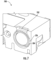
- FIG. 7 illustrates another sectional view 700 of the assembled imaging unit 116 according to one or more embodiments described herein.
- the glue 702 is uniformly distributed within the groove 526.
- the glue may tightly couple the housing 202 with the lens barrel 204. Since the groove 526 on the lens barrel 204 is of fixed size, an amount of glue to be disposed remains constant across the various imaging units as well. Accordingly, variations due to curing of the glue (e.g., movement of the lens barrel within lens channel due to curing of the glue) remain consistent during manufacturing of various imaging units. Therefore, any anticipated change in focal point of the lens barrel 204 can be compensated prior to curing of the glue.
- certain ones of the operations herein may be modified or further amplified as described below. Moreover, in some embodiments additional optional operations may also be included. It should be appreciated that each of the modifications, optional additions or amplifications described herein may be included with the operations herein either alone or in combination with any others among the features described herein.
Landscapes
- Physics & Mathematics (AREA)
- General Physics & Mathematics (AREA)
- Engineering & Computer Science (AREA)
- Multimedia (AREA)
- Signal Processing (AREA)
- Optics & Photonics (AREA)
- Lens Barrels (AREA)
- Facsimile Scanning Arrangements (AREA)
Claims (15)
- Bildaufnahmegerät (102), umfassend:eine Bildgebungseinheit (116), umfassend:
ein Gehäuse (202), das eine Innenfläche (238) umfasst, wobei die Innenfläche (238) des Gehäuses (202) einen Linsenkanal (302) definiert, wobei die Innenfläche (238) des Linsenkanals (302) definiert:einen Kontaktpunkt (414a, 414b), der nach außen von der Innenfläche (238) in den Linsenkanal (302) hervorsteht, undein Durchgangsloch (304) im Linsenkanal (302), das sich von der Innenfläche (238) des Linsenkanals (302) zu einer Außenfläche (236) des Gehäuses (202) erstreckt; undein Linsentubus (204), der im Linsenkanal (302) aufgenommen ist, wobei der Linsentubus (204) eine Außenfläche (508) umfasst, die definiert:wobei dann, wenn die erste Stufe (518) am Kontaktpunkt (414a, 414b) anliegt, die Nut (526) über das Durchgangsloch (304) freiliegt.einen ersten Abschnitt (512),eine erste Plattform (510), die sich in Umfangsrichtung um eine erste zentrale Längsachse (520) des Linsentubus (204) dreht, wobei ein Radius der ersten Plattform (510) größer ist als ein Radius des ersten Abschnitts (512), sodass eine erste Stufe (518) an einer Verbindungsstelle (516) zwischen der ersten Plattform (510) und dem ersten Abschnitt (512) definiert ist,eine Nut (526), die auf der ersten Plattform (510) definiert ist, wobei sich die Nut (526) in Umfangsrichtung um die erste zentrale Längsachse (520) des Linsentubus (204) dreht, - Bildaufnahmegerät (102) nach Anspruch 1, wobei das Definieren der Nut (526) eine erste Kante (528) und eine zweite Kante (530) in der ersten Plattform (510) erzeugt, wobei die erste Kante (528) und die zweite Kante (530) einen Umfang der Nut (526) definieren, und wobei die erste Kante (528) und die zweite Kante (530) das zweite vorbestimmte Profil aufweisen.
- Bildaufnahmegerät (102) nach Anspruch 2, wobei ein Umfang des Durchgangslochs (304) durch mindestens eine erste Kantenfläche (312), eine zweite Kantenfläche (314), eine dritte Kantenfläche (316) und eine vierte Kantenfläche (318) definiert ist, und wobei die erste Kantenfläche (312) in einem ersten Abstand von einem Kontaktpunkt (414a, 414b) entlang einer zweiten zentralen Längsachse (404) des Linsenkanals (302) positioniert ist.
- Bildaufnahmegerät (102) nach Anspruch 3, wobei die erste Stufe (518) in einem zweiten Abstand von der ersten Kante (528), die den Umfang der Nut (526) definiert, entlang der ersten zentralen Längsachse (520) des Linsentubus (204) positioniert ist, wobei der erste Abstand gleich dem zweiten Abstand ist.
- Bildaufnahmegerät (102) nach Anspruch 1, wobei die Innenfläche (238) des Gehäuses (202) eine zweite Plattform (402) und einen Linsenaufnahmeabschnitt (406) innerhalb des Linsenkanals (302) definiert, wobei ein Radius des Linsenaufnahmeabschnitts (406) größer ist als der Radius der zweiten Plattform (402), und wobei eine zweite Stufe (410) an einer Verbindungsstelle zwischen dem Linsenaufnahmeabschnitt (406) und der zweiten Plattform (402) definiert ist.
- Bildaufnahmegerät (102) nach Anspruch 5, wobei die Innenfläche (238) des Gehäuses (202) den Kontaktpunkt (414a, 414b) definiert, sodass er sich von der zweiten Stufe (410) nach außen erstreckt.
- Bildaufnahmegerät (102) nach Anspruch 1, wobei der Linsentubus (204) drehbar im Linsenkanal (302) aufgenommen ist, wobei der Kontaktpunkt (414a, 414b) auf der ersten Stufe (518) gleitend bewegbar ist, wenn der Linsentubus (204) im Linsenkanal (302) gedreht wird.
- Bildaufnahmegerät (102) nach Anspruch 3, wobei die Nut (526) über das Durchgangsloch (304) freiliegend bleibt, während der Linsentubus (204) innerhalb des Linsenkanals (302) gedreht wird.
- Gehäuse (202) einer Bildgebungseinheit (116), wobei das Gehäuse (202) umfasst:
eine Außenfläche (236) und eine Innenfläche (238), wobei die Innenfläche (238) des Gehäuses (202) definiert:
einen Linsenkanal (302), wobei die Innenfläche (238) des Linsenkanals (302) definiert:einen Kontaktpunkt (414a, 414b), der nach außen von der Innenfläche (238) in den Linsenkanal (302) hervorsteht, undein Durchgangsloch (304) im Linsenkanal (302), das sich von der Innenfläche (238) des Linsenkanals (302) zur Außenfläche (236) des Gehäuses (202) erstreckt,wobei der Linsenkanal (302) dazu konfiguriert ist, einen Linsentubus (204) aufzunehmen, der eine Nut (526) umfasst, wobei die Nut (526) zum Durchgangsloch (304) freiliegt, wenn der Linsentubus (204) im Linsenkanal (302) aufgenommen ist. - Gehäuse (202) der Bildgebungseinheit (116) nach Anspruch 9, wobei die Innenfläche (238) des Gehäuses (202) eine erste Plattform (402) und einen Linsenaufnahmeabschnitt (406) innerhalb des Linsenkanals (302) definiert, wobei ein Radius des Linsenaufnahmeabschnitts (406) größer ist als der Radius der ersten Plattform (402), und wobei eine erste Stufe (410) an einer Verbindungsstelle zwischen dem Linsenaufnahmeabschnitt (406) und der ersten Plattform (402) definiert ist.
- Gehäuse (202) der Bildgebungseinheit (116) nach Anspruch 10, wobei die Innenfläche (238) des Gehäuses (202) den Kontaktpunkt (414a, 414b) definiert, sodass er sich von der ersten Stufe (518) nach außen erstreckt.
- Gehäuse (202) der Bildgebungseinheit (116) nach Anspruch 9, wobei der Linsentubus (204) drehbar im Linsenkanal (302) aufgenommen ist, wobei der Kontaktpunkt (414a, 414b) auf einer zweiten Stufe (410), die auf dem Linsentubus (204) definiert ist, gleitend bewegbar ist, wenn der Linsentubus (204) innerhalb des Linsenkanals (302) gedreht wird.
- Gehäuse (202) der Bildgebungseinheit (116) nach Anspruch 9, wobei ein Umfang des Durchgangslochs (304) durch mindestens eine erste Kantenfläche (312), eine zweite Kantenfläche (314), eine dritte Kantenfläche (316) und eine vierte Kantenfläche (318) definiert ist, und wobei die erste Kantenfläche (312) in einem ersten Abstand von einem Kontaktpunkt (414a, 414b) entlang einer ersten zentralen Längsachse (404) des Linsenkanals (302) positioniert ist.
- Linsentubus (204), der eine Außenfläche (508) aufweist, wobei die Außenfläche (508) definiert:einen ersten Abschnitt (512),eine erste Plattform (510), die sich in Umfangsrichtung um eine erste zentrale Längsachse (520) des Linsentubus (204) dreht, wobei ein Radius der ersten Plattform (510) größer ist als ein Radius des ersten Abschnitts (512), sodass eine erste Stufe (518) an einer Verbindungsstelle (516) zwischen der ersten Plattform (510) und dem ersten Abschnitt (512) definiert ist,eine Nut (526), die auf der ersten Plattform (510) definiert ist, wobei sich die Nut (526) in Umfangsrichtung um die erste zentrale Längsachse (520) des Linsentubus (204) dreht,wobei dann, wenn die erste Stufe (518) an einem Kontaktpunkt (414a, 414b) anliegt, der in einem Linsenkanal (302) in einer Bildgebungseinheit (116) definiert ist, die Nut (526) über ein Durchgangsloch freiliegt, das in der Bildgebungseinheit (116) definiert ist.
- Linsentubus (204) nach Anspruch 14, wobei das Definieren der Nut (526) eine erste Kante (528) und eine zweite Kante (530) in der ersten Plattform (510) erzeugt, wobei die erste Kante (528) und die zweite Kante (530) einen Umfang der Nut (526) definieren und wobei die erste Kante (528) und die zweite Kante (530) das zweite vorbestimmte Profil aufweisen.
Priority Applications (1)
| Application Number | Priority Date | Filing Date | Title |
|---|---|---|---|
| EP24206464.0A EP4489419A3 (de) | 2020-09-16 | 2021-09-10 | Gehäuse einer bilderfassungsvorrichtung |
Applications Claiming Priority (1)
| Application Number | Priority Date | Filing Date | Title |
|---|---|---|---|
| CN202010975621.7A CN114268709A (zh) | 2020-09-16 | 2020-09-16 | 图像捕获装置的壳体 |
Related Child Applications (2)
| Application Number | Title | Priority Date | Filing Date |
|---|---|---|---|
| EP24206464.0A Division EP4489419A3 (de) | 2020-09-16 | 2021-09-10 | Gehäuse einer bilderfassungsvorrichtung |
| EP24206464.0A Division-Into EP4489419A3 (de) | 2020-09-16 | 2021-09-10 | Gehäuse einer bilderfassungsvorrichtung |
Publications (2)
| Publication Number | Publication Date |
|---|---|
| EP3971640A1 EP3971640A1 (de) | 2022-03-23 |
| EP3971640B1 true EP3971640B1 (de) | 2024-12-11 |
Family
ID=77738922
Family Applications (2)
| Application Number | Title | Priority Date | Filing Date |
|---|---|---|---|
| EP21196118.0A Active EP3971640B1 (de) | 2020-09-16 | 2021-09-10 | Gehäuse einer bilderfassungsvorrichtung |
| EP24206464.0A Pending EP4489419A3 (de) | 2020-09-16 | 2021-09-10 | Gehäuse einer bilderfassungsvorrichtung |
Family Applications After (1)
| Application Number | Title | Priority Date | Filing Date |
|---|---|---|---|
| EP24206464.0A Pending EP4489419A3 (de) | 2020-09-16 | 2021-09-10 | Gehäuse einer bilderfassungsvorrichtung |
Country Status (3)
| Country | Link |
|---|---|
| US (2) | US11910074B2 (de) |
| EP (2) | EP3971640B1 (de) |
| CN (1) | CN114268709A (de) |
Family Cites Families (13)
| Publication number | Priority date | Publication date | Assignee | Title |
|---|---|---|---|---|
| TWI255360B (en) * | 2002-06-19 | 2006-05-21 | Seiko Epson Corp | Production device for projection lens, production method for projection lens, projection lens produced by this production method for projection lens, and projector provided with projection lens |
| JP4645274B2 (ja) * | 2005-04-08 | 2011-03-09 | ソニー株式会社 | レンズ装置及び撮像装置 |
| CN1885908B (zh) * | 2005-06-24 | 2010-04-28 | 鸿富锦精密工业(深圳)有限公司 | 照相模组 |
| US10663714B2 (en) * | 2010-10-28 | 2020-05-26 | Endochoice, Inc. | Optical system for an endoscope |
| US11366284B2 (en) * | 2011-11-22 | 2022-06-21 | Cognex Corporation | Vision system camera with mount for multiple lens types and lens module for the same |
| US8896943B2 (en) * | 2013-03-14 | 2014-11-25 | Himax Technologies Limited | Lens assembly and method for assembling the same |
| KR20160004103A (ko) * | 2014-07-02 | 2016-01-12 | 삼성전기주식회사 | 카메라 모듈 |
| US9930234B2 (en) * | 2016-06-03 | 2018-03-27 | Gopro, Inc. | Lens and sensor positioning system |
| US10712531B2 (en) * | 2017-06-06 | 2020-07-14 | Luxvisions Innovation Limited | Lens structure and assembly method thereof |
| US10534154B2 (en) * | 2017-06-16 | 2020-01-14 | Apple Inc. | Interlock arrangement for attaching a lens barrel to a lens carrier |
| US10514524B2 (en) * | 2017-09-29 | 2019-12-24 | Symbol Technologies, Llc | Imaging devices having progressive magnification |
| US10769394B2 (en) * | 2018-03-22 | 2020-09-08 | Symbol Technologies, Llc | Devices systems and methods for alignment of lens assemblies within a chassis |
| US11283975B2 (en) | 2018-12-21 | 2022-03-22 | Welch Allyn, Inc. | Eye image capturing |
-
2020
- 2020-09-16 CN CN202010975621.7A patent/CN114268709A/zh active Pending
-
2021
- 2021-09-10 EP EP21196118.0A patent/EP3971640B1/de active Active
- 2021-09-10 EP EP24206464.0A patent/EP4489419A3/de active Pending
- 2021-09-14 US US17/447,644 patent/US11910074B2/en active Active
-
2024
- 2024-01-26 US US18/424,463 patent/US12225275B2/en active Active
Also Published As
| Publication number | Publication date |
|---|---|
| CN114268709A (zh) | 2022-04-01 |
| EP3971640A1 (de) | 2022-03-23 |
| US12225275B2 (en) | 2025-02-11 |
| EP4489419A3 (de) | 2025-04-23 |
| US11910074B2 (en) | 2024-02-20 |
| EP4489419A2 (de) | 2025-01-08 |
| US20240244304A1 (en) | 2024-07-18 |
| US20220086313A1 (en) | 2022-03-17 |
Similar Documents
| Publication | Publication Date | Title |
|---|---|---|
| US6801260B1 (en) | Automatic focusing camera with moving mirror between fixed lens and fixed image sensor | |
| EP0516837B1 (de) | Strichcodeleser mit grosser tiefenschärfe | |
| US6689998B1 (en) | Apparatus for optical distancing autofocus and imaging and method of using the same | |
| US9076199B2 (en) | System and method for determining and controlling focal distance in a vision system camera | |
| US20080239140A1 (en) | Adaptive aperture for an imaging scanner | |
| US8496173B2 (en) | Camera-based code reader and method for its adjusted manufacturing | |
| US12216329B2 (en) | Housing of an image capturing device | |
| EP2294461B1 (de) | Bildgebungssystem mit anamorpher vergrösserung | |
| KR100389625B1 (ko) | 포커스 구동모터를 이용한 디지털 스틸 카메라의 마이크로모드구현장치 | |
| JP2025065563A (ja) | 移動物体の存在下で2d視覚システムのカメラの被写界深度を広げるためのシステム及び方法 | |
| EP3971640B1 (de) | Gehäuse einer bilderfassungsvorrichtung | |
| US20070127325A1 (en) | Lens driving unit | |
| US20100086291A1 (en) | Camera module and driving method thereof | |
| US5909302A (en) | Staring scanner | |
| KR20220011519A (ko) | 카메라 액추에이터 및 이를 포함하는 카메라 모듈 | |
| CN109946769B (zh) | 减少视觉系统变焦透镜漂移的系统及方法 | |
| US6930719B2 (en) | Lens unit structure for SLR digital camera | |
| EP1028344A2 (de) | Eindimensionale Bildaufnahmeanordnung | |
| JP2020170049A (ja) | 走査光学装置 | |
| IL118997A (en) | Staring scanner | |
| JPH05142662A (ja) | 原稿読取装置 | |
| JP2001177704A (ja) | 画像読み取り光学系 |
Legal Events
| Date | Code | Title | Description |
|---|---|---|---|
| PUAI | Public reference made under article 153(3) epc to a published international application that has entered the european phase |
Free format text: ORIGINAL CODE: 0009012 |
|
| STAA | Information on the status of an ep patent application or granted ep patent |
Free format text: STATUS: REQUEST FOR EXAMINATION WAS MADE |
|
| 17P | Request for examination filed |
Effective date: 20210910 |
|
| AK | Designated contracting states |
Kind code of ref document: A1 Designated state(s): AL AT BE BG CH CY CZ DE DK EE ES FI FR GB GR HR HU IE IS IT LI LT LU LV MC MK MT NL NO PL PT RO RS SE SI SK SM TR |
|
| RIC1 | Information provided on ipc code assigned before grant |
Ipc: H04N 23/55 20230101ALI20240521BHEP Ipc: H04N 23/51 20230101ALI20240521BHEP Ipc: G03B 17/02 20210101AFI20240521BHEP |
|
| GRAP | Despatch of communication of intention to grant a patent |
Free format text: ORIGINAL CODE: EPIDOSNIGR1 |
|
| STAA | Information on the status of an ep patent application or granted ep patent |
Free format text: STATUS: GRANT OF PATENT IS INTENDED |
|
| INTG | Intention to grant announced |
Effective date: 20240722 |
|
| GRAS | Grant fee paid |
Free format text: ORIGINAL CODE: EPIDOSNIGR3 |
|
| GRAA | (expected) grant |
Free format text: ORIGINAL CODE: 0009210 |
|
| STAA | Information on the status of an ep patent application or granted ep patent |
Free format text: STATUS: THE PATENT HAS BEEN GRANTED |
|
| RAP3 | Party data changed (applicant data changed or rights of an application transferred) |
Owner name: HAND HELD PRODUCTS, INC. |
|
| AK | Designated contracting states |
Kind code of ref document: B1 Designated state(s): AL AT BE BG CH CY CZ DE DK EE ES FI FR GB GR HR HU IE IS IT LI LT LU LV MC MK MT NL NO PL PT RO RS SE SI SK SM TR |
|
| REG | Reference to a national code |
Ref country code: GB Ref legal event code: FG4D |
|
| REG | Reference to a national code |
Ref country code: CH Ref legal event code: EP |
|
| REG | Reference to a national code |
Ref country code: DE Ref legal event code: R096 Ref document number: 602021023173 Country of ref document: DE |
|
| REG | Reference to a national code |
Ref country code: IE Ref legal event code: FG4D |
|
| REG | Reference to a national code |
Ref country code: LT Ref legal event code: MG9D |
|
| PG25 | Lapsed in a contracting state [announced via postgrant information from national office to epo] |
Ref country code: HR Free format text: LAPSE BECAUSE OF FAILURE TO SUBMIT A TRANSLATION OF THE DESCRIPTION OR TO PAY THE FEE WITHIN THE PRESCRIBED TIME-LIMIT Effective date: 20241211 |
|
| PG25 | Lapsed in a contracting state [announced via postgrant information from national office to epo] |
Ref country code: FI Free format text: LAPSE BECAUSE OF FAILURE TO SUBMIT A TRANSLATION OF THE DESCRIPTION OR TO PAY THE FEE WITHIN THE PRESCRIBED TIME-LIMIT Effective date: 20241211 |
|
| PG25 | Lapsed in a contracting state [announced via postgrant information from national office to epo] |
Ref country code: BG Free format text: LAPSE BECAUSE OF FAILURE TO SUBMIT A TRANSLATION OF THE DESCRIPTION OR TO PAY THE FEE WITHIN THE PRESCRIBED TIME-LIMIT Effective date: 20241211 |
|
| REG | Reference to a national code |
Ref country code: NL Ref legal event code: MP Effective date: 20241211 |
|
| PG25 | Lapsed in a contracting state [announced via postgrant information from national office to epo] |
Ref country code: ES Free format text: LAPSE BECAUSE OF FAILURE TO SUBMIT A TRANSLATION OF THE DESCRIPTION OR TO PAY THE FEE WITHIN THE PRESCRIBED TIME-LIMIT Effective date: 20241211 |
|
| PG25 | Lapsed in a contracting state [announced via postgrant information from national office to epo] |
Ref country code: NO Free format text: LAPSE BECAUSE OF FAILURE TO SUBMIT A TRANSLATION OF THE DESCRIPTION OR TO PAY THE FEE WITHIN THE PRESCRIBED TIME-LIMIT Effective date: 20250311 |
|
| PG25 | Lapsed in a contracting state [announced via postgrant information from national office to epo] |
Ref country code: LV Free format text: LAPSE BECAUSE OF FAILURE TO SUBMIT A TRANSLATION OF THE DESCRIPTION OR TO PAY THE FEE WITHIN THE PRESCRIBED TIME-LIMIT Effective date: 20241211 Ref country code: GR Free format text: LAPSE BECAUSE OF FAILURE TO SUBMIT A TRANSLATION OF THE DESCRIPTION OR TO PAY THE FEE WITHIN THE PRESCRIBED TIME-LIMIT Effective date: 20250312 |
|
| PG25 | Lapsed in a contracting state [announced via postgrant information from national office to epo] |
Ref country code: RS Free format text: LAPSE BECAUSE OF FAILURE TO SUBMIT A TRANSLATION OF THE DESCRIPTION OR TO PAY THE FEE WITHIN THE PRESCRIBED TIME-LIMIT Effective date: 20250311 |
|
| PG25 | Lapsed in a contracting state [announced via postgrant information from national office to epo] |
Ref country code: NL Free format text: LAPSE BECAUSE OF FAILURE TO SUBMIT A TRANSLATION OF THE DESCRIPTION OR TO PAY THE FEE WITHIN THE PRESCRIBED TIME-LIMIT Effective date: 20241211 |
|
| REG | Reference to a national code |
Ref country code: AT Ref legal event code: MK05 Ref document number: 1750865 Country of ref document: AT Kind code of ref document: T Effective date: 20241211 |
|
| PG25 | Lapsed in a contracting state [announced via postgrant information from national office to epo] |
Ref country code: SM Free format text: LAPSE BECAUSE OF FAILURE TO SUBMIT A TRANSLATION OF THE DESCRIPTION OR TO PAY THE FEE WITHIN THE PRESCRIBED TIME-LIMIT Effective date: 20241211 |
|
| PG25 | Lapsed in a contracting state [announced via postgrant information from national office to epo] |
Ref country code: PL Free format text: LAPSE BECAUSE OF FAILURE TO SUBMIT A TRANSLATION OF THE DESCRIPTION OR TO PAY THE FEE WITHIN THE PRESCRIBED TIME-LIMIT Effective date: 20241211 |
|
| PG25 | Lapsed in a contracting state [announced via postgrant information from national office to epo] |
Ref country code: IS Free format text: LAPSE BECAUSE OF FAILURE TO SUBMIT A TRANSLATION OF THE DESCRIPTION OR TO PAY THE FEE WITHIN THE PRESCRIBED TIME-LIMIT Effective date: 20250411 |
|
| PG25 | Lapsed in a contracting state [announced via postgrant information from national office to epo] |
Ref country code: PT Free format text: LAPSE BECAUSE OF FAILURE TO SUBMIT A TRANSLATION OF THE DESCRIPTION OR TO PAY THE FEE WITHIN THE PRESCRIBED TIME-LIMIT Effective date: 20250411 |
|
| PG25 | Lapsed in a contracting state [announced via postgrant information from national office to epo] |
Ref country code: EE Free format text: LAPSE BECAUSE OF FAILURE TO SUBMIT A TRANSLATION OF THE DESCRIPTION OR TO PAY THE FEE WITHIN THE PRESCRIBED TIME-LIMIT Effective date: 20241211 |
|
| PG25 | Lapsed in a contracting state [announced via postgrant information from national office to epo] |
Ref country code: RO Free format text: LAPSE BECAUSE OF FAILURE TO SUBMIT A TRANSLATION OF THE DESCRIPTION OR TO PAY THE FEE WITHIN THE PRESCRIBED TIME-LIMIT Effective date: 20241211 Ref country code: AT Free format text: LAPSE BECAUSE OF FAILURE TO SUBMIT A TRANSLATION OF THE DESCRIPTION OR TO PAY THE FEE WITHIN THE PRESCRIBED TIME-LIMIT Effective date: 20241211 |
|
| PG25 | Lapsed in a contracting state [announced via postgrant information from national office to epo] |
Ref country code: SK Free format text: LAPSE BECAUSE OF FAILURE TO SUBMIT A TRANSLATION OF THE DESCRIPTION OR TO PAY THE FEE WITHIN THE PRESCRIBED TIME-LIMIT Effective date: 20241211 |
|
| PG25 | Lapsed in a contracting state [announced via postgrant information from national office to epo] |
Ref country code: CZ Free format text: LAPSE BECAUSE OF FAILURE TO SUBMIT A TRANSLATION OF THE DESCRIPTION OR TO PAY THE FEE WITHIN THE PRESCRIBED TIME-LIMIT Effective date: 20241211 |
|
| PG25 | Lapsed in a contracting state [announced via postgrant information from national office to epo] |
Ref country code: IT Free format text: LAPSE BECAUSE OF FAILURE TO SUBMIT A TRANSLATION OF THE DESCRIPTION OR TO PAY THE FEE WITHIN THE PRESCRIBED TIME-LIMIT Effective date: 20241211 |
|
| PG25 | Lapsed in a contracting state [announced via postgrant information from national office to epo] |
Ref country code: SE Free format text: LAPSE BECAUSE OF FAILURE TO SUBMIT A TRANSLATION OF THE DESCRIPTION OR TO PAY THE FEE WITHIN THE PRESCRIBED TIME-LIMIT Effective date: 20241211 |
|
| REG | Reference to a national code |
Ref country code: DE Ref legal event code: R097 Ref document number: 602021023173 Country of ref document: DE |
|
| PG25 | Lapsed in a contracting state [announced via postgrant information from national office to epo] |
Ref country code: DK Free format text: LAPSE BECAUSE OF FAILURE TO SUBMIT A TRANSLATION OF THE DESCRIPTION OR TO PAY THE FEE WITHIN THE PRESCRIBED TIME-LIMIT Effective date: 20241211 |
|
| PGFP | Annual fee paid to national office [announced via postgrant information from national office to epo] |
Ref country code: DE Payment date: 20250926 Year of fee payment: 5 |
|
| PGFP | Annual fee paid to national office [announced via postgrant information from national office to epo] |
Ref country code: GB Payment date: 20250923 Year of fee payment: 5 |
|
| PLBE | No opposition filed within time limit |
Free format text: ORIGINAL CODE: 0009261 |
|
| STAA | Information on the status of an ep patent application or granted ep patent |
Free format text: STATUS: NO OPPOSITION FILED WITHIN TIME LIMIT |
|
| 26N | No opposition filed |
Effective date: 20250912 |