EP3971499A1 - An appliance and a heat exchanger for the appliance - Google Patents
An appliance and a heat exchanger for the appliance Download PDFInfo
- Publication number
- EP3971499A1 EP3971499A1 EP21193141.5A EP21193141A EP3971499A1 EP 3971499 A1 EP3971499 A1 EP 3971499A1 EP 21193141 A EP21193141 A EP 21193141A EP 3971499 A1 EP3971499 A1 EP 3971499A1
- Authority
- EP
- European Patent Office
- Prior art keywords
- suction line
- capillary tube
- appliance
- evaporator
- looping portion
- Prior art date
- Legal status (The legal status is an assumption and is not a legal conclusion. Google has not performed a legal analysis and makes no representation as to the accuracy of the status listed.)
- Withdrawn
Links
Images




Classifications
-
- F—MECHANICAL ENGINEERING; LIGHTING; HEATING; WEAPONS; BLASTING
- F25—REFRIGERATION OR COOLING; COMBINED HEATING AND REFRIGERATION SYSTEMS; HEAT PUMP SYSTEMS; MANUFACTURE OR STORAGE OF ICE; LIQUEFACTION SOLIDIFICATION OF GASES
- F25D—REFRIGERATORS; COLD ROOMS; ICE-BOXES; COOLING OR FREEZING APPARATUS NOT OTHERWISE PROVIDED FOR
- F25D23/00—General constructional features
- F25D23/06—Walls
- F25D23/061—Walls with conduit means
-
- F—MECHANICAL ENGINEERING; LIGHTING; HEATING; WEAPONS; BLASTING
- F25—REFRIGERATION OR COOLING; COMBINED HEATING AND REFRIGERATION SYSTEMS; HEAT PUMP SYSTEMS; MANUFACTURE OR STORAGE OF ICE; LIQUEFACTION SOLIDIFICATION OF GASES
- F25B—REFRIGERATION MACHINES, PLANTS OR SYSTEMS; COMBINED HEATING AND REFRIGERATION SYSTEMS; HEAT PUMP SYSTEMS
- F25B41/00—Fluid-circulation arrangements
- F25B41/40—Fluid line arrangements
-
- F—MECHANICAL ENGINEERING; LIGHTING; HEATING; WEAPONS; BLASTING
- F25—REFRIGERATION OR COOLING; COMBINED HEATING AND REFRIGERATION SYSTEMS; HEAT PUMP SYSTEMS; MANUFACTURE OR STORAGE OF ICE; LIQUEFACTION SOLIDIFICATION OF GASES
- F25B—REFRIGERATION MACHINES, PLANTS OR SYSTEMS; COMBINED HEATING AND REFRIGERATION SYSTEMS; HEAT PUMP SYSTEMS
- F25B41/00—Fluid-circulation arrangements
- F25B41/30—Expansion means; Dispositions thereof
- F25B41/37—Capillary tubes
-
- F—MECHANICAL ENGINEERING; LIGHTING; HEATING; WEAPONS; BLASTING
- F25—REFRIGERATION OR COOLING; COMBINED HEATING AND REFRIGERATION SYSTEMS; HEAT PUMP SYSTEMS; MANUFACTURE OR STORAGE OF ICE; LIQUEFACTION SOLIDIFICATION OF GASES
- F25B—REFRIGERATION MACHINES, PLANTS OR SYSTEMS; COMBINED HEATING AND REFRIGERATION SYSTEMS; HEAT PUMP SYSTEMS
- F25B2400/00—Component parts or details not otherwise provided for in this subclass
- F25B2400/05—Compression system with heat exchange between particular parts of the system
- F25B2400/052—Compression system with heat exchange between particular parts of the system between the capillary tube and another part of the refrigeration cycle
-
- F—MECHANICAL ENGINEERING; LIGHTING; HEATING; WEAPONS; BLASTING
- F25—REFRIGERATION OR COOLING; COMBINED HEATING AND REFRIGERATION SYSTEMS; HEAT PUMP SYSTEMS; MANUFACTURE OR STORAGE OF ICE; LIQUEFACTION SOLIDIFICATION OF GASES
- F25B—REFRIGERATION MACHINES, PLANTS OR SYSTEMS; COMBINED HEATING AND REFRIGERATION SYSTEMS; HEAT PUMP SYSTEMS
- F25B2400/00—Component parts or details not otherwise provided for in this subclass
- F25B2400/05—Compression system with heat exchange between particular parts of the system
- F25B2400/054—Compression system with heat exchange between particular parts of the system between the suction tube of the compressor and another part of the cycle
-
- F—MECHANICAL ENGINEERING; LIGHTING; HEATING; WEAPONS; BLASTING
- F25—REFRIGERATION OR COOLING; COMBINED HEATING AND REFRIGERATION SYSTEMS; HEAT PUMP SYSTEMS; MANUFACTURE OR STORAGE OF ICE; LIQUEFACTION SOLIDIFICATION OF GASES
- F25D—REFRIGERATORS; COLD ROOMS; ICE-BOXES; COOLING OR FREEZING APPARATUS NOT OTHERWISE PROVIDED FOR
- F25D11/00—Self-contained movable devices, e.g. domestic refrigerators
- F25D11/02—Self-contained movable devices, e.g. domestic refrigerators with cooling compartments at different temperatures
- F25D11/022—Self-contained movable devices, e.g. domestic refrigerators with cooling compartments at different temperatures with two or more evaporators
Definitions
- the present disclosure generally relates to a heat exchanger and, more specifically, to a heat exchanger for an appliance.
- an appliance includes a refrigeration compartment defined by a plurality of interior walls.
- a freezer compartment is proximate to the refrigeration compartment.
- a compressor is positioned proximate to at least one of the refrigeration compartment and the freezer compartment.
- a first evaporator is operably coupled to the compressor.
- a suction line conveys refrigerant from the first evaporator toward the compressor.
- the suction line has a suction line looping portion that generally defines an inner suction line loop and an outer suction line loop.
- a capillary tube is operably coupled to the first evaporator and is configured to convey refrigerant to the evaporator. The capillary tube contacts the suction line looping portion, such that heat from the capillary tube is transferred to the suction line.
- an appliance includes a compressor.
- An evaporator is operably coupled to the compressor.
- a suction line is operably coupled to the evaporator and is configured to convey refrigerant from the evaporator toward the compressor.
- the suction line has a suction line looping portion that generally spirals to form a plurality of suction line loops.
- a capillary tube is operably coupled to the evaporator and is configured to convey refrigerant to the evaporator. The capillary tube contacts the suction line looping portion, such that heat from the capillary tube is transferred to the suction line.
- an appliance includes a compressor.
- An evaporator is operably coupled to the compressor.
- a suction line is operably coupled to the evaporator and is configured to convey refrigerant from the evaporator toward the compressor.
- the suction line has a suction line looping portion that extends to form at least one suction line loop.
- a pressure reduction device is thermally coupled to the suction line looping portion, such that heat from the pressure reduction device is transferred to the suction line.
- the terms “upper,” “lower,” “right,” “left,” “rear,” “front,” “vertical,” “horizontal,” and derivatives thereof shall relate to the disclosure as oriented in FIG. 1 .
- the term “front” shall refer to the surface of the element closer to an intended viewer, and the term “rear” shall refer to the surface of the element further from the intended viewer.
- the disclosure may assume various alternative orientations, except where expressly specified to the contrary.
- the specific devices and processes illustrated in the attached drawings, and described in the following specification are simply exemplary embodiments of the inventive concepts defined in the appended claims. Hence, specific dimensions and other physical characteristics relating to the embodiments disclosed herein are not to be considered as limiting, unless the claims expressly state otherwise.
- a reference numeral designates the appliance.
- the appliance 10 includes a refrigeration compartment 12 that is defined by a plurality of interior walls 14.
- a freezer compartment 16 is positioned proximate to the refrigeration compartment 12.
- a compressor 18 is positioned proximate to at least one of the refrigeration compartment 12 and the freezer compartment 16.
- a first evaporator 20 is operably coupled to the compressor 18.
- a suction line 24 is operably coupled to the first evaporator 20 and is configured to convey refrigerant 22 from the first evaporator 20 toward the compressor 18.
- the suction line 24 includes a suction line looping portion 26 that generally defines an inner suction line loop 28 and an outer suction line loop 30.
- a capillary tube 32 is operably coupled to the first evaporator 20 and is configured to convey refrigerant 22 to the first evaporator 20.
- the capillary tube 32 is configured to contact the suction line looping portion 26, such that heat from the capillary tube 32 is transferred to the suction line 24.
- the appliance 10 includes a top 34 and a bottom 36 opposite the top 34.
- a front side 38 and a rear side 40 opposite the front side 38 extend between the top 34 and the bottom 36.
- a right side 42 and a left side 44 opposite the right side 42 are disposed between the front and rear sides 38, 40 and extend between the top 34 and the bottom 36.
- Exterior surfaces 46 of the appliance 10, such as trim or paneling may comprise the top 34, bottom 36, rear side 40, left side 44, and/or right side 42 of the appliance 10.
- the appliance 10 includes a refrigeration compartment door 48 and a freezer compartment door 50.
- the refrigeration and freezer compartment doors 48, 50 are coupled to the appliance 10 proximate to the front side 38 and are operable between closed positions and open positions, as illustrated in FIG. 1 . In the closed positions (not shown), the exterior surfaces 46 of the refrigeration and freezer compartment doors 48, 50 may be the front side 38 of the appliance 10. In the illustrated embodiment, the refrigeration compartment door 48 provides access to the refrigeration compartment 12 and a sub compartment 52 positioned between the refrigeration compartment 12 and the freezer compartment 16. A variety of styles of appliances with varying numbers of compartments and/or doors are contemplated.
- the refrigeration compartment 12 is positioned nearer to the top 34 of the appliance 10 than the freezer compartment 16. As such, the appliance 10 is configured as a bottom freezer refrigeration appliance.
- the refrigeration compartment 12 is defined by the plurality of interior walls 14. As illustrated in FIG.
- the refrigeration compartment 12 is defined by a first side interior wall 54 proximate to the left side 44 of the appliance 10, a second side interior wall 56 opposite the first side interior wall 54 and proximate to the right side 42 of the appliance 10, a rear interior wall 58 positioned between the first and second side interior walls 54, 56 and generally proximate to the rear side 40 of the appliance 10, an upper interior wall 60 extending outward from the rear interior wall 58, between the first and second side interior walls 54, 56, and generally proximate to the top 34 of the appliance 10, and a lower interior wall 62 extending between the first and second side interior walls 54, 56 opposite the upper interior wall 60.
- At least one air circulation opening 64 may be defined by and/or extend through at least one of the plurality of interior walls 14 that define the refrigeration compartment 12.
- a plurality of air circulation openings 64 are defined by the rear interior wall 58.
- the air circulation openings 64 may enhance air circulation within the refrigeration compartment 12 by allowing air being pushed over the first evaporator 20 by a first evaporator fan 66 to flow into the refrigeration compartment 12, as described further herein.
- the appliance 10 includes a cooling system 68 that utilizes a refrigerant circuit 70.
- the compressor 18 supplies refrigerant 22 through a compressor outlet line 72 to a condenser 74, as illustrated in FIGS. 2 and 3 and shown schematically in FIG. 4 .
- the compressor 18 and the condenser 74 are positioned within a machine compartment 76 of the appliance 10 that is adjacent to the freezer compartment 16 proximate to the bottom and rear side 36, 40 of the appliance 10.
- the condenser 74 is paired with a condenser fan 78, which is shown schematically in FIG.
- the condenser fan 78 operates to further improve the efficiency of the condenser 74 by imparting a flow of ambient air over the condenser 74. This additional air flow over the condenser 74 facilitates additional heat transfer (i.e., heat removal) during the phase change of refrigerant 22 from a gas to a liquid within the condenser 74.
- valve system 82 is configured as a single, three-way valve assembly 84 configured to direct and/or restrict flow of the refrigerant 22 to the first evaporator 20 and/or a second evaporator 86.
- valve system 82 may be configured as two, one-way valve assemblies for accomplishing the same function as the one, three-way valve assembly 84.
- a first one-way valve (not shown) may be arranged upstream from the first evaporator 20 and a second one-way valve (not shown) may be arranged upstream from the second evaporator 86. Both one-way valves can then be operated to direct or restrict flow of refrigerant 22 to one or both of the first and second evaporators 20, 86.
- a variety of configurations of the valve system 82 are contemplated.
- Both lines leading into the first and second evaporators 20, 86 from the valve system 82 are configured with pressure reduction devices 88.
- the refrigerant 22 that flows to the first evaporator 20 flows through a first pressure reduction device 90 and refrigerant 22 that flows to the second evaporator 86 flows through a second pressure reduction device 92.
- the pressure reduction devices 88 may be at least one of a variety of devices configured to reduce pressure that includes, but is not limited to, capillary tubes, expansion valves, orifice restrictors, needle valves and/or a combination thereof.
- first and second pressure reduction devices 90, 92 can each be configured to subject the refrigerant 22 to particular pressure reduction levels according to the particular design and operational needs of the appliance 10.
- the first pressure reduction device 90 is illustrated as the capillary tube 32.
- the first pressure reduction device 90 is the capillary tube 32.
- the refrigerant 22 When refrigerant 22 existing in a liquid state flows through the first pressure reduction device 90 and/or the second pressure reduction device 92, the refrigerant 22 experiences a significant pressure and temperature drop. Thus, a substantial quantity of refrigerant 22 flashes to a vapor state during flow through the first and/or second pressure reduction devices 90, 92.
- the refrigerant 22 may be composed of one or more of a variety of conventional coolants employed in the refrigeration industry.
- the refrigerant 22 may be R-134a, R-600a or other recognized refrigerants for vapor compression systems.
- the refrigerant 22 After flowing through the first and second pressure reduction devices 90, 92, the refrigerant 22 enters the first and second evaporators 20, 86, respectively.
- the first evaporator 20 is arranged in thermal communication with the refrigeration compartment 12. As illustrated in FIGS. 5 and 6 , the first evaporator 20 is positioned between the rear side 40 of the appliance 10 and the rear interior wall 58 of the refrigeration compartment 12 and between the freezer compartment 16 and the top 34 of the appliance 10. As illustrated in FIG. 5 , the first evaporator fan 66 is positioned within the appliance 10 proximate to the first evaporator 20 and is configured to direct warm air over the first evaporator 20.
- Flow of refrigerant 22 through the first evaporator 20 cools the warm air as it flows over the first evaporator 20.
- the cooled air flows through the air circulation openings 64 defined by the rear interior wall 58 into the refrigeration compartment 12, which cools the refrigeration compartment 12.
- the second evaporator 86 is in thermal communication with the freezer compartment 16. As illustrated in FIG. 5 , the second evaporator 86 is positioned adjacent to the freezer compartment 16, and a second evaporator fan 94 is positioned proximate to the second evaporator 86. The second evaporator fan 94 directs warm air over the second evaporator 86. This cools the air, which in turn, cools the freezer compartment 16 in thermal communication with the second evaporator 86.
- a first suction line 96 exits the first evaporator 20, and a second suction line 98 exits the second evaporator 86.
- a check valve 100 is provided on the second suction line 98.
- the first and second suction lines 96, 98 join in a compressor inlet line 102 that extends to the compressor 18.
- the appliance 10 may include a controller that is configured to control a variety of components involved in the refrigerant circuit 70 (e.g., compressor 18, valve system 82, etc.) to operate the cooling system 68.
- the first suction line 96 and the first pressure reduction device 90 coupled to the first evaporator 20 are configured to form a heat exchanger 104, wherein heat from the first pressure reduction device 90 is transferred to the first suction line 96.
- the first suction line 96 includes the suction line looping portion 26.
- the suction line looping portion 26 includes at least one suction line loop 105.
- the first suction line 96 is configured to extend, such that the first suction line 96 forms at least one loop.
- the suction line looping portion 26 may generally define a plurality of suction line loops 105.
- the suction line looping portion 26 may generally spiral to form a plurality of suction line loops 105. Further, in some examples, the suction line looping portion 26 may generally spiral in a progressively widening fashion to create a plurality of suction line loops 105 of varying sizes.
- the suction line looping portion 26 generally spirals in a progressively widening fashion to form the inner suction line loop 28 and the outer suction line loop 30.
- the first suction line 96 initially extends upward from the first evaporator 20.
- the first suction line 96 then turns toward the left side 44 of the appliance 10, loops clockwise, and crosses over itself on the side of the first suction line 96 nearer to the front side 38 of the appliance 10 to form the inner suction line loop 28.
- the section of the first suction line 96 that extends upward from the first evaporator 20 to the beginning of the inner suction line loop 28 may be referred to as the suction line standing end 106.
- the inner suction line loop 28 begins by extending from the suction line standing end 106 and terminates by crossing over the suction line standing end 106.
- the outer suction line loop 30 begins. Like the inner suction line loop 28, the outer suction line loop 30 initially extends toward the left side 44 of the appliance 10, then loops clockwise and crosses over the suction line standing end 106. As illustrated in FIG. 8 , the outer suction line loop 30 crosses over the suction line standing end 106 between the front of the refrigeration compartment 12 and the suction line standing end 106. Because the suction line looping portion 26 generally spirals in a progressively widening fashion to define the inner and outer suction line loops 28, 30, the outer suction line loop 30 loops generally around and outside of the inner suction line loop 28. As such, the outer suction line loop 30 is longer than the inner suction line loop 28 and crosses the suction line standing end 106 between the first evaporator 20 and the inner suction line loop 28.
- the outer suction line loop 30 crosses over the suction line standing end 106, the outer suction line loop 30 ends and a suction line tag end 108 begins. As illustrated in FIG. 8 , the suction line tag end 108 extends along the outside of the outer suction line loop 30 toward the left side 44 of the appliance 10 and then upward toward the top 34 of the appliance 10 before extending further toward the left side 44 of the appliance 10 away from the outer suction line loop 30 and downward toward the bottom 36 of the appliance 10.
- the suction line tag end 108 of the first suction line 96 is operably coupled with the compressor 18, such that the refrigerant 22 flows through the first evaporator 20, into the suction line standing end 106, through the inner suction line loop 28, through the outer suction line loop 30, into the suction line tag end 108, and then on to the compressor 18.
- the inner and outer suction line loops 28, 30 include a plurality of elongated portions.
- the inner suction line loop 28 includes an inner lower portion 110 that extends from the suction line standing end 106 toward the left side 44 of the appliance 10, a first inner side portion 112 extends upward from the inner lower portion 110 toward the top 34 of the appliance 10, an inner upper portion 114 that extends from the first inner side portion 112 toward the right side 42 of the appliance 10, and a second inner side portion 116 that extends downward from the inner upper portion 114 toward the bottom 36 of the appliance 10.
- the outer suction line loop 30 includes an outer lower portion 118 that extends from the suction line standing end 106 toward the left side 44 of the appliance 10, a first outer side portion 120 extends upward from the outer lower portion 118 toward the top 34 of the appliance 10, an outer upper portion 122 that extends from the first outer side portion 120 toward the right side 42 of the appliance 10, and a second outer side portion 124 that extends downward from the outer upper portion 122 toward the bottom 36 of the appliance 10.
- the inner upper and lower portions 114, 110 may be generally parallel to each other, and the first and second inner side portions 112, 116 may be generally parallel to each other and/or generally perpendicular to the inner upper and lower portions 114, 110.
- the outer upper and lower portions 122, 118 may be generally parallel to each other, and the first and second outer side portions 120, 124 may be generally parallel to each other and/or generally perpendicular to the outer upper and lower portions 122, 118.
- the corresponding portions of the inner and outer suction line loops 28, 30 may be generally parallel to each other.
- the inner and outer upper portions 114, 122 may be generally parallel to each other, and the first inner and outer side portions 112, 120 may be generally parallel to each other.
- the elongated portions of the inner and outer suction line loops 28, 30 may be connected to each other via a plurality of corners 126.
- a plurality of generally rounded corners 126 connect the portions of the inner and outer suction line loops 28, 30, and the first and second inner and outer side portions 112, 116, 120, 124 are longer than the inner and outer lower and upper portions 110, 118, 114, 122, respectively, such that the inner and outer suction line loops 28, 30 are generally stadium shaped.
- the inner and outer upper portions 114, 122 are spaced apart from each other to the greatest extent.
- the inner and outer upper portions 114, 122 are positioned a distance from each other that is greater than the distances between the inner and outer lower portions 110, 118, the first inner and outer side portions 112, 120, and the second inner and outer side portions 116, 124, respectively.
- the inner and outer suction line loops 28, 30 may be aligned with each other in a forward-rearward direction of the appliance 10, such that a flat spiral is formed.
- the inner and outer suction line loops 28, 30 may be configured to spiral without extending toward the front side 38 or the rear side 40 of the appliance 10.
- the suction line looping portion 26 may be positioned adjacent to other sides of the appliance 10, such as the left side 44, and that the suction line looping portion 26 may form a flat spiral that loops without extending toward the left side 44 or right side 42 of the appliance 10.
- a variety of suction line looping portion 26 designs are contemplated. For example, suction line looping portions 26 having more or fewer loops, a variety of loop shapes (circular, rectangular, oval, etc.), and various loop sizes, are contemplated.
- the first pressure reduction device 90 is configured to form a heat exchanger 104 with the suction line looping portion 26 of the first suction line 96.
- the first pressure reduction device 90 is the capillary tube 32.
- the capillary tube 32 may be thermally coupled to and/or in contact with the suction line looping portion 26 of the first suction line 96, such that heat may be transferred from the capillary tube 32 to the first suction line 96.
- the capillary tube 32 may be soldered to the suction line looping portion 26.
- the capillary tube 32 and the suction line looping portion 26 may be thermally coupled and held in contact with each other by vinyl heat shrink tubing disposed about the capillary tube 32 and suction line looping portion 26. Further, in some embodiments, the capillary tube 32 and the suction line looping portion 26 may be thermally coupled and held in contact with each other by aluminum tape adhered to the capillary tube 32 and the suction line looping portion 26. In some examples, the aluminum tape may extend generally parallel to the directions of extension of the capillary tube 32 and the suction line looping portion 26.
- the aluminum tape may extend generally perpendicularly to the directions of extension of the capillary tube 32 and the suction line looping portion 26 and wrap around the capillary tube 32 and the suction line looping portion 26.
- the capillary tube 32 includes a capillary tube looping portion 128.
- the capillary tube looping portion 128 includes at least one capillary tube loop 130.
- the capillary tube 32 is configured to extend, such that the capillary tube 32 forms at least one loop.
- the capillary tube looping portion 128 may generally define a plurality of capillary tube loops 130.
- the capillary tube looping portion 128 may generally spiral to form a plurality of capillary tube loops 130.
- the capillary tube looping portion 128 may generally spiral in a progressively widening fashion to form a plurality of capillary tube loops 130 of varying sizes.
- the capillary tube looping portion 128 generally spirals in a progressively widening fashion to form an inner capillary tube loop 132 and an outer capillary tube loop 134.
- a capillary tube standing end 136 extends outward from the first evaporator 20.
- the capillary tube 32 extends from the capillary tube standing end 136 toward the left side 44 of the appliance 10, loops clockwise, and crosses over the capillary tube standing end 136 to form the inner capillary tube loop 132.
- the outer capillary tube loop 134 begins. Like the inner capillary tube loop 132, the outer capillary tube loop 134 initially extends toward the left side 44 of the appliance 10, then loops clockwise and crosses over the capillary tube standing end 136. Because the capillary tube looping portion 128 generally spirals in a progressively widening fashion to define the inner and outer capillary tube loops 132, 134, the outer capillary tube loop 134 loops generally around and outside of the inner capillary tube loop 132. As such, the outer capillary tube loop 134 is longer than the inner capillary tube loop 132 and crosses the capillary tube standing end 136 between the first evaporator 20 and the inner capillary tube loop 132.
- the outer capillary tube loop 134 crosses over the capillary tube standing end 136, the outer capillary tube loop 134 ends and a capillary tube tag end 138 begins.
- the capillary tube tag end 138 extends along the outside of the outer capillary tube loop 134 toward the left side 44 of the appliance 10 and then upward toward the top 34 of the appliance 10 before extending further toward the left side 44 of the appliance 10 away from the outer capillary tube loop 134 and downward toward the bottom 36 of the appliance 10.
- the inner and outer capillary tube loops 132, 134 extend along and generally form the same shapes as the inner and outer suction line loops 28, 30, respectively.
- the capillary tube looping portion 128 extending along the suction line looping portion 26 in this manner may allow a large portion of the capillary tube looping portion 128 to be thermally coupled with and/or in contact with the suction line looping portion 26, which may increase heat transfer from the capillary tube 32 to the first suction line 96.
- the suction line and capillary tube looping portions 26, 128 may form an efficient heat exchanger 104.
- At least one of the plurality of interior walls 14 may be positioned between the refrigeration compartment 12 and the suction line looping portion 26 and/or between the refrigeration compartment 12 and the capillary tube looping portion 128.
- the suction line looping portion 26 and/or the capillary tube looping portion 128 may be positioned between the rear side 40 of the appliance 10 and the rear interior wall 58 of appliance 10 that defines the refrigeration compartment 12, such that the rear interior wall 58 is positioned between the refrigeration compartment 12 and the suction line looping portion 26 and/or the capillary tube looping portion 128, as illustrated in FIGS. 5 and 6 .
- the first evaporator 20 may be positioned between the rear interior wall 58 and the rear side 40 of the appliance 10.
- the suction line looping portion 26 is positioned a first distance from the top 34 of the appliance 10
- the first evaporator 20 is positioned a second distance from the top 34 of the appliance 10, wherein the second distance is greater than the first distance.
- the suction line looping portion 26 is positioned nearer than the first evaporator 20 to the top 34 of the appliance 10.
- the second evaporator 86 is positioned a third distance from the top 34 of the appliance 10, wherein the third distance is greater than the second distance.
- the first evaporator 20 is nearer than the second evaporator 86 to the top 34 of the appliance 10.
- the suction line looping portion 26 may be positioned adjacent to at least one of the plurality of interior walls 14 of the appliance 10, such that at least one air circulation opening 64 defined by the at least one of the plurality of interior walls 14 may be disposed generally between the inner and outer suction line loops 28, 30 of the suction line looping portion 26. Further, in some implementations, the suction line looping portion 26 may be positioned such that the inner and outer suction line loops 28, 30 generally spiral around the at least one air circulation opening 64 defined by the at least one of the plurality of interior walls 14.
- the suction line looping portion 26 is illustrated in phantom in FIG. 7 positioned adjacent to the refrigeration compartment 12, above the first evaporator 20, and rearward of the rear interior wall 58 that defines the refrigeration compartment 12 (i.e., between the rear interior wall 58 and the rear side 40 of the appliance 10).
- the rear interior wall 58 defines eight air circulation openings 64.
- the inner suction line loop 28 loops around three of the air circulation openings 64
- the outer suction line loop 30 loops around those three air circulation openings 64, and additionally, loops around a fourth air circulation opening 64 positioned upward of the inner suction line loop 28 (i.e., between the inner suction line loop 28 and the top 34 of the appliance 10).
- the inner and outer suction line loops 28, 30 generally spiral around the three air circulation openings 64, and the fourth air circulation opening 64 is disposed generally between the inner and outer suction line loops 28, 30.
- the air circulation opening 64 positioned between the inner and outer suction line loops 28, 30 is positioned between the inner upper portion 114 and the outer upper portion 122 of the inner and outer suction line loops 28, 30, respectively.
- the inner and outer capillary tube loops 132, 134 likewise, loop about at least one of the air circulation openings 64, and at least one of the air circulation openings 64 is positioned between the inner and outer capillary tube loops 132, 134.
- Positioning the suction line looping portion 26 and/or the capillary tube looping portion 128 in this manner may be advantageous, as the suction line looping portion 26 and/or the capillary tube looping portion 128 may not be visible through the plurality of air circulation openings 64 to a user looking into the refrigeration compartment 12.
- the present disclosure may provide a variety of additional advantages.
- the first suction line 96 having the suction line looping portion 26 increases the length of the first suction line 96, which increases the length of the heat exchanger 104, which may increase the coefficient of performance of the refrigerant circuit 70.
- the suction line looping portion 26 and the capillary tube looping portion 128 being thermally coupled to form the heat exchanger 104 may aid in reducing liquid flood-back problems within the refrigerant circuit 70 that can negatively impact compressor life and cause condensation to accumulate on the first suction line 96. As such, improved compressor life may result from the heat exchanger 104.
- the suction line looping portion 26 and the capillary tube looping portion 128 may form a heat exchanger 104 that is space efficient compared to other components typically used to avoid liquid flood back (e.g., an accumulator, etc.).
- the suction line looping portion 26 and the capillary tube looping portion 128 being utilized to form the heat exchanger 104 may reduce structure borne noise and airborne noise of the appliance 10 relative to conventional systems.
- an appliance includes a refrigeration compartment defined by a plurality of interior walls.
- a freezer compartment is proximate to the refrigeration compartment.
- a compressor is positioned proximate to at least one of the refrigeration compartment and the freezer compartment.
- a first evaporator is operably coupled to the compressor.
- a suction line conveys refrigerant from the first evaporator toward the compressor.
- the suction line has a suction line looping portion that generally defines an inner suction line loop and an outer suction line loop.
- a capillary tube is operably coupled to the first evaporator and is configured to convey refrigerant to the evaporator. The capillary tube contacts the suction line looping portion, such that heat from the capillary tube is transferred to the suction line.
- At least one of the plurality of interior walls is positioned between the refrigeration compartment and the suction line looping portion and the at least one of the plurality of interior walls defines an air circulation opening disposed generally between the inner and outer suction line loops.
- At least one of the plurality of interior walls is positioned between the refrigeration compartment and the suction line looping portion and the at least one of the plurality of interior walls defines an air circulation opening.
- the inner and outer suction line loops generally spiral around the air circulation opening.
- the appliance includes a top and a bottom opposite the top.
- the refrigeration compartment is nearer than the freezer compartment to the top.
- the suction line looping portion is positioned a first distance from the top, and the first evaporator is positioned a second distance from the top. The second distance is greater than the first distance.
- the appliance includes a second evaporator operably coupled to the compressor and positioned proximate to the freezer compartment a third distance from the top.
- the third distance is greater than the second distance.
- the capillary tube includes a capillary tube looping portion that generally spirals in a progressively widening fashion to form an inner capillary tube loop and an outer capillary tube loop.
- the capillary tube looping portion contacts the suction line looping portion, such that heat is transferred from the capillary tube to the suction line.
- the appliance includes a compressor.
- An evaporator is operably coupled to the compressor.
- a suction line is operably coupled to the evaporator and configured to convey refrigerant from the evaporator toward the compressor.
- the suction line has a suction line looping portion that generally spirals to form a plurality of suction line loops.
- a capillary tube is operably coupled to the evaporator and is configured to convey refrigerant to the evaporator. The capillary tube contacts the suction line looping portion, such that heat from the capillary tube is transferred to the suction line.
- the suction line looping portion generally spirals in a progressively widening fashion to form an inner suction line loop and an outer suction line loop.
- the capillary tube includes a capillary tube looping portion that generally spirals to form a plurality of capillary tube loops.
- the capillary tube looping portion contacts the suction line looping portion, such that heat is transferred from the capillary tube to the suction line.
- the capillary tube looping portion generally spirals in a progressively widening fashion to form an inner capillary tube loop and an outer capillary tube loop.
- the appliance includes a top, a bottom opposite the top, a freezer compartment proximate to the bottom, and a refrigeration compartment nearer than the freezer compartment to the top.
- the suction line looping portion is positioned a first distance from the top, and the evaporator is positioned a second distance from the top. The second distance is greater than the first distance.
- the suction line looping portion is positioned between the top and the freezer compartment and is adjacent to the refrigeration compartment.
- an appliance includes a compressor.
- An evaporator is operably coupled to the compressor.
- a suction line is operably coupled to the evaporator and is configured to convey refrigerant from the evaporator toward the compressor.
- the suction line has a suction line looping portion that extends to form at least one suction line loop.
- a pressure reduction device is thermally coupled to the suction line looping portion, such that heat from the pressure reduction device is transferred to the suction line.
- the suction line looping portion generally spirals to form a plurality of suction line loops.
- the suction line looping portion generally spirals in a progressively widening fashion to form an inner suction line loop and an outer suction line loop.
- the pressure reduction device includes a capillary tube operably coupled to the evaporator and configured to convey refrigerant to the evaporator.
- the capillary tube is configured to contact the suction line looping portion, such that heat from the capillary tube is transferred to the suction line.
- the pressure reduction device includes a capillary tube operably coupled to the evaporator and configured to convey refrigerant to the evaporator.
- the capillary tube has a capillary tube looping portion that generally spirals to form a plurality of capillary tube loops.
- the capillary tube looping portion contacts the suction line looping portion, such that heat is transferred from the capillary tube to the suction line.
- the pressure reduction device includes a capillary tube operably coupled to the evaporator and configured to convey refrigerant to the evaporator.
- the capillary tube has a capillary tube looping portion that generally spirals to form an inner capillary tube loop and an outer capillary tube loop.
- the capillary tube looping portion contacts the suction line looping portion, such that heat is transferred from the capillary tube to the suction line.
Landscapes
- Engineering & Computer Science (AREA)
- Physics & Mathematics (AREA)
- Mechanical Engineering (AREA)
- Thermal Sciences (AREA)
- General Engineering & Computer Science (AREA)
- Chemical & Material Sciences (AREA)
- Combustion & Propulsion (AREA)
- Devices That Are Associated With Refrigeration Equipment (AREA)
- Heat-Exchange Devices With Radiators And Conduit Assemblies (AREA)
Abstract
An appliance (10) includes a refrigeration compartment (12) that is defined by a plurality of interior walls (14). A freezer compartment (16) is positioned proximate to the refrigeration compartment (12). A compressor (18) is positioned proximate to at least one of the refrigeration compartment (12) and the freezer compartment (16). A first evaporator (20) is operably coupled to the compressor (18). A suction line (24) is operably coupled to the first evaporator (20) and is configured to convey refrigerant (22) from the first evaporator (20) toward the compressor (18). The suction line (24) includes a suction line looping portion (26) that generally defines an inner suction line loop (28) and an outer suction line loop (30). A capillary tube (32) is operably coupled to the first evaporator (20) and is configured to convey refrigerant (22) to the first evaporator (20). The capillary tube (32) is configured to contact the suction line looping portion (26), such that heat from the capillary tube (32) is transferred to the suction line (24).
Description
- The present disclosure generally relates to a heat exchanger and, more specifically, to a heat exchanger for an appliance.
- According to one aspect of the present disclosure, an appliance includes a refrigeration compartment defined by a plurality of interior walls. A freezer compartment is proximate to the refrigeration compartment. A compressor is positioned proximate to at least one of the refrigeration compartment and the freezer compartment. A first evaporator is operably coupled to the compressor. A suction line conveys refrigerant from the first evaporator toward the compressor. The suction line has a suction line looping portion that generally defines an inner suction line loop and an outer suction line loop. A capillary tube is operably coupled to the first evaporator and is configured to convey refrigerant to the evaporator. The capillary tube contacts the suction line looping portion, such that heat from the capillary tube is transferred to the suction line.
- According to another aspect of the present disclosure, an appliance includes a compressor. An evaporator is operably coupled to the compressor. A suction line is operably coupled to the evaporator and is configured to convey refrigerant from the evaporator toward the compressor. The suction line has a suction line looping portion that generally spirals to form a plurality of suction line loops. A capillary tube is operably coupled to the evaporator and is configured to convey refrigerant to the evaporator. The capillary tube contacts the suction line looping portion, such that heat from the capillary tube is transferred to the suction line.
- According to another aspect of the present disclosure, an appliance includes a compressor. An evaporator is operably coupled to the compressor. A suction line is operably coupled to the evaporator and is configured to convey refrigerant from the evaporator toward the compressor. The suction line has a suction line looping portion that extends to form at least one suction line loop. A pressure reduction device is thermally coupled to the suction line looping portion, such that heat from the pressure reduction device is transferred to the suction line.
- These and other features, advantages, and objects of the present invention will be further understood and appreciated by those skilled in the art by reference to the following specification, claims, and appended drawings.
- In the drawings:
-
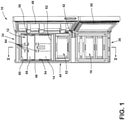
FIG. 1 is a front elevational view of an appliance of the present disclosure; -
FIG. 2 is a rear elevational view of the appliance ofFIG. 1 showing a machine compartment; -
FIG. 3 is a rear elevational view of the machine compartment ofFIG. 2 taken at area III; -
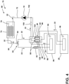
FIG. 4 is a schematic diagram of a refrigeration cycle of an appliance of the present disclosure; -
FIG. 5 is a cross-sectional view of the appliance ofFIG. 1 taken at line V-V showing an evaporator and a suction line coupled to the evaporator; -
FIG. 6 is an enlarged view of the evaporator and the suction line ofFIG. 5 taken at area VI; -
FIG. 7 is a partial front elevational view of the refrigeration compartment of the appliance showing a rear interior wall of the refrigeration compartment defining a plurality of air circulation openings, a suction line looping portion of the suction line in phantom, and a capillary tube looping portion of the capillary tube in phantom; -
FIG. 8 is a partial front elevational view of a rear portion of a refrigeration compartment of the appliance showing the evaporator, the suction line looping portion, and the capillary tube looping portion; and -
FIG. 9 is a front elevational view of a suction line looping portion, and a capillary looping portion of the present disclosure. - The components in the figures are not necessarily to scale, emphasis instead being placed upon illustrating the principles described herein.
- For purposes of description herein, the terms "upper," "lower," "right," "left," "rear," "front," "vertical," "horizontal," and derivatives thereof shall relate to the disclosure as oriented in
FIG. 1 . Unless stated otherwise, the term "front" shall refer to the surface of the element closer to an intended viewer, and the term "rear" shall refer to the surface of the element further from the intended viewer. However, it is to be understood that the disclosure may assume various alternative orientations, except where expressly specified to the contrary. It is also to be understood that the specific devices and processes illustrated in the attached drawings, and described in the following specification, are simply exemplary embodiments of the inventive concepts defined in the appended claims. Hence, specific dimensions and other physical characteristics relating to the embodiments disclosed herein are not to be considered as limiting, unless the claims expressly state otherwise. - Referring to
FIGS. 1-9 , a reference numeral designates the appliance. Theappliance 10 includes arefrigeration compartment 12 that is defined by a plurality ofinterior walls 14. Afreezer compartment 16 is positioned proximate to therefrigeration compartment 12. Acompressor 18 is positioned proximate to at least one of therefrigeration compartment 12 and thefreezer compartment 16. Afirst evaporator 20 is operably coupled to thecompressor 18. Asuction line 24 is operably coupled to thefirst evaporator 20 and is configured to conveyrefrigerant 22 from thefirst evaporator 20 toward thecompressor 18. Thesuction line 24 includes a suctionline looping portion 26 that generally defines an innersuction line loop 28 and an outersuction line loop 30. Acapillary tube 32 is operably coupled to thefirst evaporator 20 and is configured to conveyrefrigerant 22 to thefirst evaporator 20. Thecapillary tube 32 is configured to contact the suctionline looping portion 26, such that heat from thecapillary tube 32 is transferred to thesuction line 24. - Referring now to
FIGS. 1-5 theappliance 10 includes atop 34 and abottom 36 opposite thetop 34. Afront side 38 and arear side 40 opposite thefront side 38 extend between thetop 34 and thebottom 36. Aright side 42 and aleft side 44 opposite theright side 42 are disposed between the front andrear sides top 34 and thebottom 36.Exterior surfaces 46 of theappliance 10, such as trim or paneling, may comprise thetop 34,bottom 36,rear side 40,left side 44, and/orright side 42 of theappliance 10. As illustrated inFIG. 1 , theappliance 10 includes arefrigeration compartment door 48 and afreezer compartment door 50. The refrigeration andfreezer compartment doors appliance 10 proximate to thefront side 38 and are operable between closed positions and open positions, as illustrated inFIG. 1 . In the closed positions (not shown), theexterior surfaces 46 of the refrigeration andfreezer compartment doors front side 38 of theappliance 10. In the illustrated embodiment, therefrigeration compartment door 48 provides access to therefrigeration compartment 12 and asub compartment 52 positioned between therefrigeration compartment 12 and thefreezer compartment 16. A variety of styles of appliances with varying numbers of compartments and/or doors are contemplated. - Referring further to
FIGS. 1-5 , therefrigeration compartment 12 is positioned nearer to thetop 34 of theappliance 10 than thefreezer compartment 16. As such, theappliance 10 is configured as a bottom freezer refrigeration appliance. Therefrigeration compartment 12 is defined by the plurality ofinterior walls 14. As illustrated inFIG. 1 , therefrigeration compartment 12 is defined by a first sideinterior wall 54 proximate to theleft side 44 of theappliance 10, a secondside interior wall 56 opposite the firstside interior wall 54 and proximate to theright side 42 of theappliance 10, a rearinterior wall 58 positioned between the first and second sideinterior walls rear side 40 of theappliance 10, an upperinterior wall 60 extending outward from the rearinterior wall 58, between the first and second sideinterior walls top 34 of theappliance 10, and a lowerinterior wall 62 extending between the first and second sideinterior walls interior wall 60. - In some implementations, at least one air circulation opening 64 may be defined by and/or extend through at least one of the plurality of
interior walls 14 that define therefrigeration compartment 12. For example, in the embodiment illustrated inFIG. 1 , a plurality ofair circulation openings 64 are defined by the rearinterior wall 58. Theair circulation openings 64 may enhance air circulation within therefrigeration compartment 12 by allowing air being pushed over thefirst evaporator 20 by a firstevaporator fan 66 to flow into therefrigeration compartment 12, as described further herein. - Referring now to
FIGS. 2-8 , theappliance 10 includes acooling system 68 that utilizes arefrigerant circuit 70. In therefrigerant circuit 70, thecompressor 18 supplies refrigerant 22 through acompressor outlet line 72 to acondenser 74, as illustrated inFIGS. 2 and3 and shown schematically inFIG. 4 . In the embodiment of theappliance 10 illustrated inFIGS. 2 and3 , thecompressor 18 and thecondenser 74 are positioned within amachine compartment 76 of theappliance 10 that is adjacent to thefreezer compartment 16 proximate to the bottom andrear side appliance 10. Thecondenser 74 is paired with acondenser fan 78, which is shown schematically inFIG. 4 and illustrated within themachine compartment 76 inFIG. 3 . Thecondenser fan 78 operates to further improve the efficiency of thecondenser 74 by imparting a flow of ambient air over thecondenser 74. This additional air flow over thecondenser 74 facilitates additional heat transfer (i.e., heat removal) during the phase change of refrigerant 22 from a gas to a liquid within thecondenser 74. - Next, the refrigerant 22 exits the
condenser 74 via a conduit, passes through afilter 80, and is presented to avalve system 82. In the schematic diagram inFIG. 4 , thevalve system 82 is configured as a single, three-way valve assembly 84 configured to direct and/or restrict flow of the refrigerant 22 to thefirst evaporator 20 and/or asecond evaporator 86. Alternatively, thevalve system 82 may be configured as two, one-way valve assemblies for accomplishing the same function as the one, three-way valve assembly 84. In implementations where theappliance 10 employs a dual, one-way valve configuration for thevalve system 82 within therefrigerant circuit 70, a first one-way valve (not shown) may be arranged upstream from thefirst evaporator 20 and a second one-way valve (not shown) may be arranged upstream from thesecond evaporator 86. Both one-way valves can then be operated to direct or restrict flow ofrefrigerant 22 to one or both of the first andsecond evaporators valve system 82 are contemplated. - Both lines leading into the first and
second evaporators valve system 82 are configured withpressure reduction devices 88. Thus, after passing through thevalve system 82, the refrigerant 22 that flows to thefirst evaporator 20 flows through a firstpressure reduction device 90 and refrigerant 22 that flows to thesecond evaporator 86 flows through a secondpressure reduction device 92. Thepressure reduction devices 88 may be at least one of a variety of devices configured to reduce pressure that includes, but is not limited to, capillary tubes, expansion valves, orifice restrictors, needle valves and/or a combination thereof. Furthermore, the first and secondpressure reduction devices appliance 10. InFIGS. 7-9 , the firstpressure reduction device 90 is illustrated as thecapillary tube 32. Likewise, inFIG. 4 , the firstpressure reduction device 90 is thecapillary tube 32. - When refrigerant 22 existing in a liquid state flows through the first
pressure reduction device 90 and/or the secondpressure reduction device 92, the refrigerant 22 experiences a significant pressure and temperature drop. Thus, a substantial quantity of refrigerant 22 flashes to a vapor state during flow through the first and/or secondpressure reduction devices - After flowing through the first and second
pressure reduction devices second evaporators first evaporator 20 is arranged in thermal communication with therefrigeration compartment 12. As illustrated inFIGS. 5 and 6 , thefirst evaporator 20 is positioned between therear side 40 of theappliance 10 and the rearinterior wall 58 of therefrigeration compartment 12 and between thefreezer compartment 16 and the top 34 of theappliance 10. As illustrated inFIG. 5 , the firstevaporator fan 66 is positioned within theappliance 10 proximate to thefirst evaporator 20 and is configured to direct warm air over thefirst evaporator 20. Flow ofrefrigerant 22 through thefirst evaporator 20 cools the warm air as it flows over thefirst evaporator 20. The cooled air flows through theair circulation openings 64 defined by the rearinterior wall 58 into therefrigeration compartment 12, which cools therefrigeration compartment 12. - The
second evaporator 86 is in thermal communication with thefreezer compartment 16. As illustrated inFIG. 5 , thesecond evaporator 86 is positioned adjacent to thefreezer compartment 16, and a secondevaporator fan 94 is positioned proximate to thesecond evaporator 86. The secondevaporator fan 94 directs warm air over thesecond evaporator 86. This cools the air, which in turn, cools thefreezer compartment 16 in thermal communication with thesecond evaporator 86. - As illustrated in
FIG. 4 , afirst suction line 96 exits thefirst evaporator 20, and asecond suction line 98 exits thesecond evaporator 86. Acheck valve 100 is provided on thesecond suction line 98. The first andsecond suction lines compressor inlet line 102 that extends to thecompressor 18. The refrigerant 22, thus, flows from the first andsecond evaporators second suction lines compressor inlet line 102, and back to thecompressor 18. In various implementations, theappliance 10 may include a controller that is configured to control a variety of components involved in the refrigerant circuit 70 (e.g.,compressor 18,valve system 82, etc.) to operate thecooling system 68. - Referring now to
FIGS. 4-9 , thefirst suction line 96 and the firstpressure reduction device 90 coupled to thefirst evaporator 20 are configured to form aheat exchanger 104, wherein heat from the firstpressure reduction device 90 is transferred to thefirst suction line 96. Thefirst suction line 96 includes the suctionline looping portion 26. The suctionline looping portion 26 includes at least onesuction line loop 105. In other words, thefirst suction line 96 is configured to extend, such that thefirst suction line 96 forms at least one loop. In some examples, the suctionline looping portion 26 may generally define a plurality ofsuction line loops 105. In some implementations, the suctionline looping portion 26 may generally spiral to form a plurality ofsuction line loops 105. Further, in some examples, the suctionline looping portion 26 may generally spiral in a progressively widening fashion to create a plurality ofsuction line loops 105 of varying sizes. - For example, in the embodiment illustrated in
FIGS. 7-9 , the suctionline looping portion 26 generally spirals in a progressively widening fashion to form the innersuction line loop 28 and the outersuction line loop 30. As viewed inFIG. 8 , thefirst suction line 96 initially extends upward from thefirst evaporator 20. Thefirst suction line 96 then turns toward theleft side 44 of theappliance 10, loops clockwise, and crosses over itself on the side of thefirst suction line 96 nearer to thefront side 38 of theappliance 10 to form the innersuction line loop 28. The section of thefirst suction line 96 that extends upward from thefirst evaporator 20 to the beginning of the innersuction line loop 28 may be referred to as the suctionline standing end 106. As such, the innersuction line loop 28 begins by extending from the suctionline standing end 106 and terminates by crossing over the suctionline standing end 106. - As the inner
suction line loop 28 crosses over the suctionline standing end 106, the outersuction line loop 30 begins. Like the innersuction line loop 28, the outersuction line loop 30 initially extends toward theleft side 44 of theappliance 10, then loops clockwise and crosses over the suctionline standing end 106. As illustrated inFIG. 8 , the outersuction line loop 30 crosses over the suctionline standing end 106 between the front of therefrigeration compartment 12 and the suctionline standing end 106. Because the suctionline looping portion 26 generally spirals in a progressively widening fashion to define the inner and outersuction line loops suction line loop 30 loops generally around and outside of the innersuction line loop 28. As such, the outersuction line loop 30 is longer than the innersuction line loop 28 and crosses the suctionline standing end 106 between thefirst evaporator 20 and the innersuction line loop 28. - As the outer
suction line loop 30 crosses over the suctionline standing end 106, the outersuction line loop 30 ends and a suctionline tag end 108 begins. As illustrated inFIG. 8 , the suctionline tag end 108 extends along the outside of the outersuction line loop 30 toward theleft side 44 of theappliance 10 and then upward toward the top 34 of theappliance 10 before extending further toward theleft side 44 of theappliance 10 away from the outersuction line loop 30 and downward toward the bottom 36 of theappliance 10. The suctionline tag end 108 of thefirst suction line 96 is operably coupled with thecompressor 18, such that the refrigerant 22 flows through thefirst evaporator 20, into the suctionline standing end 106, through the innersuction line loop 28, through the outersuction line loop 30, into the suctionline tag end 108, and then on to thecompressor 18. - As illustrated in
FIGS. 8 and 9 , the inner and outersuction line loops suction line loop 28 includes an innerlower portion 110 that extends from the suctionline standing end 106 toward theleft side 44 of theappliance 10, a firstinner side portion 112 extends upward from the innerlower portion 110 toward the top 34 of theappliance 10, an innerupper portion 114 that extends from the firstinner side portion 112 toward theright side 42 of theappliance 10, and a secondinner side portion 116 that extends downward from the innerupper portion 114 toward the bottom 36 of theappliance 10. Further, the outersuction line loop 30 includes an outerlower portion 118 that extends from the suctionline standing end 106 toward theleft side 44 of theappliance 10, a firstouter side portion 120 extends upward from the outerlower portion 118 toward the top 34 of theappliance 10, an outerupper portion 122 that extends from the firstouter side portion 120 toward theright side 42 of theappliance 10, and a secondouter side portion 124 that extends downward from the outerupper portion 122 toward the bottom 36 of theappliance 10. - As illustrated in
FIGS. 8 and 9 , the inner upper andlower portions inner side portions lower portions lower portions outer side portions lower portions suction line loops upper portions outer side portions - Referring still to
FIGS. 7-9 , the elongated portions of the inner and outersuction line loops corners 126. As illustrated inFIGS. 8 and 9 , a plurality of generally roundedcorners 126 connect the portions of the inner and outersuction line loops outer side portions upper portions suction line loops suction line loops FIGS. 7-9 , the inner and outerupper portions upper portions lower portions outer side portions outer side portions - As illustrated in
FIGS. 5 and 6 , the inner and outersuction line loops appliance 10, such that a flat spiral is formed. In other words, apart from the circumference of thefirst suction line 96, the inner and outersuction line loops front side 38 or therear side 40 of theappliance 10. It is contemplated, that in some examples, the suctionline looping portion 26 may be positioned adjacent to other sides of theappliance 10, such as theleft side 44, and that the suctionline looping portion 26 may form a flat spiral that loops without extending toward theleft side 44 orright side 42 of theappliance 10. A variety of suctionline looping portion 26 designs are contemplated. For example, suctionline looping portions 26 having more or fewer loops, a variety of loop shapes (circular, rectangular, oval, etc.), and various loop sizes, are contemplated. - Referring now to
FIGS. 7-9 , the firstpressure reduction device 90 is configured to form aheat exchanger 104 with the suctionline looping portion 26 of thefirst suction line 96. In the embodiment illustrated inFIGS. 7-9 , the firstpressure reduction device 90 is thecapillary tube 32. Thecapillary tube 32 may be thermally coupled to and/or in contact with the suctionline looping portion 26 of thefirst suction line 96, such that heat may be transferred from thecapillary tube 32 to thefirst suction line 96. In some embodiments, thecapillary tube 32 may be soldered to the suctionline looping portion 26. In some embodiments, thecapillary tube 32 and the suctionline looping portion 26 may be thermally coupled and held in contact with each other by vinyl heat shrink tubing disposed about thecapillary tube 32 and suctionline looping portion 26. Further, in some embodiments, thecapillary tube 32 and the suctionline looping portion 26 may be thermally coupled and held in contact with each other by aluminum tape adhered to thecapillary tube 32 and the suctionline looping portion 26. In some examples, the aluminum tape may extend generally parallel to the directions of extension of thecapillary tube 32 and the suctionline looping portion 26. Further, in some examples, the aluminum tape may extend generally perpendicularly to the directions of extension of thecapillary tube 32 and the suctionline looping portion 26 and wrap around thecapillary tube 32 and the suctionline looping portion 26. Thecapillary tube 32 includes a capillarytube looping portion 128. The capillarytube looping portion 128 includes at least onecapillary tube loop 130. In other words, thecapillary tube 32 is configured to extend, such that thecapillary tube 32 forms at least one loop. In some examples, the capillarytube looping portion 128 may generally define a plurality ofcapillary tube loops 130. In some implementations, the capillarytube looping portion 128 may generally spiral to form a plurality ofcapillary tube loops 130. Further, in some examples, the capillarytube looping portion 128 may generally spiral in a progressively widening fashion to form a plurality ofcapillary tube loops 130 of varying sizes. - For example, in the embodiment illustrated in
FIGS. 7-9 , the capillarytube looping portion 128 generally spirals in a progressively widening fashion to form an innercapillary tube loop 132 and an outercapillary tube loop 134. As viewed inFIG. 8 , a capillarytube standing end 136 extends outward from thefirst evaporator 20. Thecapillary tube 32 extends from the capillarytube standing end 136 toward theleft side 44 of theappliance 10, loops clockwise, and crosses over the capillarytube standing end 136 to form the innercapillary tube loop 132. - As the inner
capillary tube loop 132 crosses over the capillarytube standing end 136, the outercapillary tube loop 134 begins. Like the innercapillary tube loop 132, the outercapillary tube loop 134 initially extends toward theleft side 44 of theappliance 10, then loops clockwise and crosses over the capillarytube standing end 136. Because the capillarytube looping portion 128 generally spirals in a progressively widening fashion to define the inner and outercapillary tube loops capillary tube loop 134 loops generally around and outside of the innercapillary tube loop 132. As such, the outercapillary tube loop 134 is longer than the innercapillary tube loop 132 and crosses the capillarytube standing end 136 between thefirst evaporator 20 and the innercapillary tube loop 132. - As the outer
capillary tube loop 134 crosses over the capillarytube standing end 136, the outercapillary tube loop 134 ends and a capillarytube tag end 138 begins. As illustrated inFIG. 8 , the capillarytube tag end 138 extends along the outside of the outercapillary tube loop 134 toward theleft side 44 of theappliance 10 and then upward toward the top 34 of theappliance 10 before extending further toward theleft side 44 of theappliance 10 away from the outercapillary tube loop 134 and downward toward the bottom 36 of theappliance 10. - As illustrated in
FIGS. 8 and 9 , the inner and outercapillary tube loops suction line loops tube looping portion 128 extending along the suctionline looping portion 26 in this manner may allow a large portion of the capillarytube looping portion 128 to be thermally coupled with and/or in contact with the suctionline looping portion 26, which may increase heat transfer from thecapillary tube 32 to thefirst suction line 96. The suction line and capillarytube looping portions efficient heat exchanger 104. - Referring now to
FIGS. 5-7 , in various implementations, at least one of the plurality ofinterior walls 14 may be positioned between therefrigeration compartment 12 and the suctionline looping portion 26 and/or between therefrigeration compartment 12 and the capillarytube looping portion 128. For example, the suctionline looping portion 26 and/or the capillarytube looping portion 128 may be positioned between therear side 40 of theappliance 10 and the rearinterior wall 58 ofappliance 10 that defines therefrigeration compartment 12, such that the rearinterior wall 58 is positioned between therefrigeration compartment 12 and the suctionline looping portion 26 and/or the capillarytube looping portion 128, as illustrated inFIGS. 5 and 6 . - In various implementations, the
first evaporator 20 may be positioned between the rearinterior wall 58 and therear side 40 of theappliance 10. In the embodiment illustrated inFIG. 4 , the suctionline looping portion 26 is positioned a first distance from the top 34 of theappliance 10, and thefirst evaporator 20 is positioned a second distance from the top 34 of theappliance 10, wherein the second distance is greater than the first distance. In other words, the suctionline looping portion 26 is positioned nearer than thefirst evaporator 20 to the top 34 of theappliance 10. Further, as illustrated inFIG. 4 , thesecond evaporator 86 is positioned a third distance from the top 34 of theappliance 10, wherein the third distance is greater than the second distance. In other words, thefirst evaporator 20 is nearer than thesecond evaporator 86 to the top 34 of theappliance 10. - In some implementations, the suction
line looping portion 26 may be positioned adjacent to at least one of the plurality ofinterior walls 14 of theappliance 10, such that at least oneair circulation opening 64 defined by the at least one of the plurality ofinterior walls 14 may be disposed generally between the inner and outersuction line loops line looping portion 26. Further, in some implementations, the suctionline looping portion 26 may be positioned such that the inner and outersuction line loops air circulation opening 64 defined by the at least one of the plurality ofinterior walls 14. - For example, the suction
line looping portion 26 is illustrated in phantom inFIG. 7 positioned adjacent to therefrigeration compartment 12, above thefirst evaporator 20, and rearward of the rearinterior wall 58 that defines the refrigeration compartment 12 (i.e., between the rearinterior wall 58 and therear side 40 of the appliance 10). In the illustrated embodiment, the rearinterior wall 58 defines eightair circulation openings 64. As illustrated, the innersuction line loop 28 loops around three of theair circulation openings 64, and the outersuction line loop 30 loops around those threeair circulation openings 64, and additionally, loops around a fourthair circulation opening 64 positioned upward of the inner suction line loop 28 (i.e., between the innersuction line loop 28 and the top 34 of the appliance 10). As such, the inner and outersuction line loops air circulation openings 64, and the fourthair circulation opening 64 is disposed generally between the inner and outersuction line loops air circulation opening 64 positioned between the inner and outersuction line loops upper portion 114 and the outerupper portion 122 of the inner and outersuction line loops capillary tube loops air circulation openings 64, and at least one of theair circulation openings 64 is positioned between the inner and outercapillary tube loops line looping portion 26 and/or the capillarytube looping portion 128 in this manner may be advantageous, as the suctionline looping portion 26 and/or the capillarytube looping portion 128 may not be visible through the plurality ofair circulation openings 64 to a user looking into therefrigeration compartment 12. - The present disclosure may provide a variety of additional advantages. First, the
first suction line 96 having the suctionline looping portion 26 increases the length of thefirst suction line 96, which increases the length of theheat exchanger 104, which may increase the coefficient of performance of therefrigerant circuit 70. Second, the suctionline looping portion 26 and the capillarytube looping portion 128 being thermally coupled to form theheat exchanger 104 may aid in reducing liquid flood-back problems within therefrigerant circuit 70 that can negatively impact compressor life and cause condensation to accumulate on thefirst suction line 96. As such, improved compressor life may result from theheat exchanger 104. Third, the suctionline looping portion 26 and the capillarytube looping portion 128 may form aheat exchanger 104 that is space efficient compared to other components typically used to avoid liquid flood back (e.g., an accumulator, etc.). Fourth, the suctionline looping portion 26 and the capillarytube looping portion 128 being utilized to form theheat exchanger 104 may reduce structure borne noise and airborne noise of theappliance 10 relative to conventional systems. - According to one aspect, an appliance includes a refrigeration compartment defined by a plurality of interior walls. A freezer compartment is proximate to the refrigeration compartment. A compressor is positioned proximate to at least one of the refrigeration compartment and the freezer compartment. A first evaporator is operably coupled to the compressor. A suction line conveys refrigerant from the first evaporator toward the compressor. The suction line has a suction line looping portion that generally defines an inner suction line loop and an outer suction line loop. A capillary tube is operably coupled to the first evaporator and is configured to convey refrigerant to the evaporator. The capillary tube contacts the suction line looping portion, such that heat from the capillary tube is transferred to the suction line.
- According to another aspect, at least one of the plurality of interior walls is positioned between the refrigeration compartment and the suction line looping portion and the at least one of the plurality of interior walls defines an air circulation opening disposed generally between the inner and outer suction line loops.
- According to another aspect, at least one of the plurality of interior walls is positioned between the refrigeration compartment and the suction line looping portion and the at least one of the plurality of interior walls defines an air circulation opening. The inner and outer suction line loops generally spiral around the air circulation opening.
- According to another aspect, the appliance includes a top and a bottom opposite the top. The refrigeration compartment is nearer than the freezer compartment to the top.
- According to another aspect, the suction line looping portion is positioned a first distance from the top, and the first evaporator is positioned a second distance from the top. The second distance is greater than the first distance.
- According to another aspect, the appliance includes a second evaporator operably coupled to the compressor and positioned proximate to the freezer compartment a third distance from the top. The third distance is greater than the second distance.
- According to another aspect, the capillary tube includes a capillary tube looping portion that generally spirals in a progressively widening fashion to form an inner capillary tube loop and an outer capillary tube loop. The capillary tube looping portion contacts the suction line looping portion, such that heat is transferred from the capillary tube to the suction line.
- According to another aspect, the appliance includes a compressor. An evaporator is operably coupled to the compressor. A suction line is operably coupled to the evaporator and configured to convey refrigerant from the evaporator toward the compressor. The suction line has a suction line looping portion that generally spirals to form a plurality of suction line loops. A capillary tube is operably coupled to the evaporator and is configured to convey refrigerant to the evaporator. The capillary tube contacts the suction line looping portion, such that heat from the capillary tube is transferred to the suction line.
- According to another aspect, the suction line looping portion generally spirals in a progressively widening fashion to form an inner suction line loop and an outer suction line loop.
- According to another aspect, the capillary tube includes a capillary tube looping portion that generally spirals to form a plurality of capillary tube loops. The capillary tube looping portion contacts the suction line looping portion, such that heat is transferred from the capillary tube to the suction line.
- According to another aspect, the capillary tube looping portion generally spirals in a progressively widening fashion to form an inner capillary tube loop and an outer capillary tube loop.
- According to another aspect, the appliance includes a top, a bottom opposite the top, a freezer compartment proximate to the bottom, and a refrigeration compartment nearer than the freezer compartment to the top.
- According to another aspect, the suction line looping portion is positioned a first distance from the top, and the evaporator is positioned a second distance from the top. The second distance is greater than the first distance.
- According to another aspect, the suction line looping portion is positioned between the top and the freezer compartment and is adjacent to the refrigeration compartment.
- According to another aspect, an appliance includes a compressor. An evaporator is operably coupled to the compressor. A suction line is operably coupled to the evaporator and is configured to convey refrigerant from the evaporator toward the compressor. The suction line has a suction line looping portion that extends to form at least one suction line loop. A pressure reduction device is thermally coupled to the suction line looping portion, such that heat from the pressure reduction device is transferred to the suction line.
- According to another aspect, the suction line looping portion generally spirals to form a plurality of suction line loops.
- According to another aspect, the suction line looping portion generally spirals in a progressively widening fashion to form an inner suction line loop and an outer suction line loop.
- According to another aspect, the pressure reduction device includes a capillary tube operably coupled to the evaporator and configured to convey refrigerant to the evaporator. The capillary tube is configured to contact the suction line looping portion, such that heat from the capillary tube is transferred to the suction line.
- According to another aspect, the pressure reduction device includes a capillary tube operably coupled to the evaporator and configured to convey refrigerant to the evaporator. The capillary tube has a capillary tube looping portion that generally spirals to form a plurality of capillary tube loops. The capillary tube looping portion contacts the suction line looping portion, such that heat is transferred from the capillary tube to the suction line.
- According to another aspect, the pressure reduction device includes a capillary tube operably coupled to the evaporator and configured to convey refrigerant to the evaporator. The capillary tube has a capillary tube looping portion that generally spirals to form an inner capillary tube loop and an outer capillary tube loop. The capillary tube looping portion contacts the suction line looping portion, such that heat is transferred from the capillary tube to the suction line.
Claims (15)
- An appliance (10), comprising:a top (34);a bottom (36) opposite the top (34);a compressor (18);a first evaporator (20) operably coupled to the compressor (18);a suction line (24) operably coupled to the first evaporator (20) and configured to convey refrigerant (22) from the first evaporator (20) toward the compressor (18), the suction line (24) having a suction line looping portion (26) that extends to form at least one suction line loop (105); anda pressure reduction device (88) thermally coupled to the suction line looping portion (26), such that heat from the pressure reduction device (88) is transferred to the suction line (24).
- The appliance (10) of claim 1, further comprising:a refrigeration compartment (12) defined by a plurality of interior walls (14); anda freezer compartment (16) proximate to the refrigeration compartment (12).
- The appliance (10) of claim 2, wherein the refrigeration compartment (12) is between the freezer compartment (16) and the top (34).
- The appliance (10) of anyone of claims 2 and 3, wherein the suction line looping portion (26) is positioned a first distance from the top (34), and the first evaporator (20) is positioned a second distance from the top (34), wherein the second distance is greater than the first distance.
- The appliance (10) of claim 4, further comprising:
a second evaporator (86) operably coupled to the compressor (18) and positioned proximate to the freezer compartment (16) a third distance from the top (34), wherein the third distance is greater than the second distance. - The appliance (10) of any one of claims 2-5, wherein the suction line looping portion (26) is positioned between the top (34) and the freezer compartment (16) and is adjacent to the refrigeration compartment (12).
- The appliance (10) of any one of claims 1-6, wherein the suction line looping portion (26) generally spirals to form a plurality of suction line loops (105).
- The appliance (10) of any one of claims 2-6, wherein the suction line looping portion (26) generally spirals in a progressively widening fashion to form an inner suction line loop (28) and an outer suction line loop (30).
- The appliance (10) of any one of claims 2-6 and 8, wherein the pressure reduction device (88) comprises:
a capillary tube (32) operably coupled to the first evaporator (20) and configured to convey refrigerant (22) to the first evaporator (20), the capillary tube (32) being configured to contact the suction line looping portion (26), such that heat from the capillary tube (32) is transferred to the suction line (24). - The appliance (10) of any one of claims 2-6 and 8, wherein the pressure reduction device (88) comprises:
a capillary tube (32) operably coupled to the first evaporator (20) and configured to convey refrigerant (22) to the first evaporator (20), the capillary tube (32) having a capillary tube looping portion (128) that generally spirals to form a plurality of capillary tube loops (130), wherein the capillary tube looping portion (128) contacts the suction line looping portion (26), such that heat is transferred from the capillary tube (32) to the suction line (24). - The appliance (10) of any one of claims 2-6 and 8, wherein the pressure reduction device (88) comprises:
a capillary tube (32) operably coupled to the first evaporator (20) and configured to convey refrigerant (22) to the first evaporator (20), the capillary tube (32) having a capillary tube looping portion (128) that generally spirals to form an inner capillary tube loop (132) and an outer capillary tube loop (134), wherein the capillary tube looping portion (128) contacts the suction line looping portion (26), such that heat is transferred from the capillary tube (32) to the suction line (24). - The appliance (10) of claim 8, wherein at least one of the plurality of interior walls (14) is positioned between the refrigeration compartment (12) and the suction line looping portion (26) and the at least one of the plurality of interior walls (14) defines an air circulation opening (64) disposed generally between the inner and outer suction line loops (28), (30).
- The appliance (10) of claim 8, wherein at least one of the plurality of interior walls (14) is positioned between the refrigeration compartment (12) and the suction line looping portion (26) and the at least one of the plurality of interior walls (14) defines an air circulation opening (64), wherein the inner and outer suction line loops (28), (30) generally spiral around the air circulation opening (64).
- The appliance (10) of claim 8, wherein at least one of the plurality of interior walls (14) is positioned between the refrigeration compartment (12) and the suction line looping portion (26) and the at least one of the plurality of interior walls (14) defines a first air circulation opening (64) disposed generally between the inner and outer suction line loops (28), (30), and a second air circulation opening (64), wherein the inner and outer suction line loops (28), (30) generally spiral around the second air circulation opening (64).
- The appliance 10 of claim 8, wherein at least one of the plurality of interior walls (14) is positioned between the refrigeration compartment (12) and the suction line looping portion (26) and the at least one of the plurality of interior walls (14) defines eight air circulation openings (64), wherein the inner suction line loop (28) loops around three of the air circulation openings (64), and the outer suction line loop (30) loops around those three air circulation openings (64), and, additionally, around a fourth air circulation opening (64).
Applications Claiming Priority (1)
| Application Number | Priority Date | Filing Date | Title |
|---|---|---|---|
| US17/027,203 US11828504B2 (en) | 2020-09-21 | 2020-09-21 | Heat exchanger for an appliance |
Publications (1)
| Publication Number | Publication Date |
|---|---|
| EP3971499A1 true EP3971499A1 (en) | 2022-03-23 |
Family
ID=77518940
Family Applications (1)
| Application Number | Title | Priority Date | Filing Date |
|---|---|---|---|
| EP21193141.5A Withdrawn EP3971499A1 (en) | 2020-09-21 | 2021-08-25 | An appliance and a heat exchanger for the appliance |
Country Status (3)
| Country | Link |
|---|---|
| US (1) | US11828504B2 (en) |
| EP (1) | EP3971499A1 (en) |
| CN (1) | CN114294887A (en) |
Families Citing this family (2)
| Publication number | Priority date | Publication date | Assignee | Title |
|---|---|---|---|---|
| US12320571B2 (en) | 2023-04-10 | 2025-06-03 | Whirlpool Corporation | Thermal improvements in vis refrigerators |
| DE102023212101B4 (en) * | 2023-12-01 | 2025-06-12 | BSH Hausgeräte GmbH | Refrigeration device and method for assembling a refrigeration device |
Citations (7)
| Publication number | Priority date | Publication date | Assignee | Title |
|---|---|---|---|---|
| US2181856A (en) * | 1938-01-29 | 1939-11-28 | Westinghouse Electric & Mfg Co | Refrigeration apparatus |
| DE1601015A1 (en) * | 1967-11-14 | 1970-06-18 | Bauknecht Gmbh G | Process for cooling cooling rooms and cooling equipment for carrying out the process |
| JPH09113096A (en) * | 1995-10-20 | 1997-05-02 | Fujitsu General Ltd | Electric refrigerator |
| JP2002181398A (en) * | 2000-12-11 | 2002-06-26 | Toshiba Corp | refrigerator |
| DE112017000376T5 (en) * | 2016-01-15 | 2018-09-27 | Lg Electronics Inc. | Freezer |
| US20190195543A1 (en) * | 2017-12-22 | 2019-06-27 | Electrolux Home Products, Inc. | Direct cooling ice maker |
| DE102019200673A1 (en) * | 2019-01-21 | 2020-07-23 | BSH Hausgeräte GmbH | Refrigerator with automatically defrostable evaporator |
Family Cites Families (11)
| Publication number | Priority date | Publication date | Assignee | Title |
|---|---|---|---|---|
| US2161293A (en) | 1938-03-30 | 1939-06-06 | Gen Motors Corp | Refrigerating apparatus |
| GB886234A (en) | 1957-08-15 | 1962-01-03 | English Electric Co Ltd | Improvements in and relating to tube condensers for refrigerators |
| JP2002364946A (en) | 2001-06-07 | 2002-12-18 | Sanoh Industrial Co Ltd | Forced air cooling condenser |
| EP1549898A1 (en) | 2002-05-29 | 2005-07-06 | Lg Electronics Inc. | Heat exchanger for refrigerator and method for anufacturing refrigerant tube of the same |
| US6848268B1 (en) * | 2003-11-20 | 2005-02-01 | Modine Manufacturing Company | CO2 cooling system |
| KR100785116B1 (en) * | 2006-01-03 | 2007-12-11 | 엘지전자 주식회사 | Refrigerator |
| KR101938713B1 (en) * | 2012-02-24 | 2019-01-16 | 삼성전자주식회사 | Refrigerator |
| KR20140091285A (en) * | 2013-01-11 | 2014-07-21 | 위니아만도 주식회사 | Suction pipe and capillary tube assembly for refrigerator |
| KR20160046713A (en) * | 2014-10-21 | 2016-04-29 | 엘지전자 주식회사 | Defrosting device and refrigerator having the same |
| KR102838162B1 (en) * | 2019-08-21 | 2025-07-25 | 엘지전자 주식회사 | Controlling method for refrigerating system using non-azeotropic mixed refrigerant |
| CN111141070A (en) * | 2020-01-21 | 2020-05-12 | 五邑大学 | Plug-in equipment and air conditioner with freezing function |
-
2020
- 2020-09-21 US US17/027,203 patent/US11828504B2/en active Active
-
2021
- 2021-08-25 EP EP21193141.5A patent/EP3971499A1/en not_active Withdrawn
- 2021-09-15 CN CN202111080789.2A patent/CN114294887A/en active Pending
Patent Citations (7)
| Publication number | Priority date | Publication date | Assignee | Title |
|---|---|---|---|---|
| US2181856A (en) * | 1938-01-29 | 1939-11-28 | Westinghouse Electric & Mfg Co | Refrigeration apparatus |
| DE1601015A1 (en) * | 1967-11-14 | 1970-06-18 | Bauknecht Gmbh G | Process for cooling cooling rooms and cooling equipment for carrying out the process |
| JPH09113096A (en) * | 1995-10-20 | 1997-05-02 | Fujitsu General Ltd | Electric refrigerator |
| JP2002181398A (en) * | 2000-12-11 | 2002-06-26 | Toshiba Corp | refrigerator |
| DE112017000376T5 (en) * | 2016-01-15 | 2018-09-27 | Lg Electronics Inc. | Freezer |
| US20190195543A1 (en) * | 2017-12-22 | 2019-06-27 | Electrolux Home Products, Inc. | Direct cooling ice maker |
| DE102019200673A1 (en) * | 2019-01-21 | 2020-07-23 | BSH Hausgeräte GmbH | Refrigerator with automatically defrostable evaporator |
Also Published As
| Publication number | Publication date |
|---|---|
| CN114294887A (en) | 2022-04-08 |
| US20220090831A1 (en) | 2022-03-24 |
| US11828504B2 (en) | 2023-11-28 |
Similar Documents
| Publication | Publication Date | Title |
|---|---|---|
| US20070169510A1 (en) | Unit for refrigerant cycle device | |
| US6519970B1 (en) | High-side refrigeration unit assembly | |
| KR20090006419A (en) | Refrigerator | |
| JP3617083B2 (en) | Receiver integrated refrigerant condenser | |
| JPH11132596A (en) | Refrigerator | |
| JP3557628B2 (en) | Recipient integrated refrigerant condenser | |
| US11828504B2 (en) | Heat exchanger for an appliance | |
| US6640583B2 (en) | Heat exchanger with intertwined inner and outer coils | |
| US11092369B2 (en) | Integrated suction header assembly | |
| US7073347B2 (en) | Evaporator for a refrigeration system | |
| US10330357B2 (en) | Air conditioner and cooling receiver of air conditioner | |
| WO2018093764A1 (en) | Hybrid heat exchanger | |
| EP2772706B1 (en) | Refrigeration system having a dual suction port compressor | |
| US8820111B2 (en) | De-super heater chiller system with contra flow and refrigerating fan grill | |
| US11898781B2 (en) | Gas header, heat exchanger, and refrigeration cycle apparatus | |
| EP1800076B1 (en) | Refrigerator | |
| US10012421B2 (en) | Evaporator for an appliance | |
| CN114729791A (en) | Expansion device for refrigeration equipment | |
| KR100556760B1 (en) | Refrigerator with dual condenser | |
| CN213931535U (en) | Double-machine double-loop system single-fan type water cooler | |
| US7730742B2 (en) | Accelerated heat exchanger | |
| CN112601921B (en) | Refrigerator with a door | |
| EP2132503A2 (en) | Evaporator integrated duct and refrigerator having the same | |
| KR20180090420A (en) | Heat exchanging device for refrigerator | |
| KR200161963Y1 (en) | A refrigerator having two series joined evaporator |
Legal Events
| Date | Code | Title | Description |
|---|---|---|---|
| PUAI | Public reference made under article 153(3) epc to a published international application that has entered the european phase |
Free format text: ORIGINAL CODE: 0009012 |
|
| STAA | Information on the status of an ep patent application or granted ep patent |
Free format text: STATUS: THE APPLICATION HAS BEEN PUBLISHED |
|
| AK | Designated contracting states |
Kind code of ref document: A1 Designated state(s): AL AT BE BG CH CY CZ DE DK EE ES FI FR GB GR HR HU IE IS IT LI LT LU LV MC MK MT NL NO PL PT RO RS SE SI SK SM TR |
|
| STAA | Information on the status of an ep patent application or granted ep patent |
Free format text: STATUS: THE APPLICATION IS DEEMED TO BE WITHDRAWN |
|
| 18D | Application deemed to be withdrawn |
Effective date: 20220924 |