EP3971427B1 - Verbindungssystem zum verbinden von mindestens zwei, insbesondere plattenartigen elementen; anordnung mit einem derartigen verbindungssystem - Google Patents
Verbindungssystem zum verbinden von mindestens zwei, insbesondere plattenartigen elementen; anordnung mit einem derartigen verbindungssystem Download PDFInfo
- Publication number
- EP3971427B1 EP3971427B1 EP21197527.1A EP21197527A EP3971427B1 EP 3971427 B1 EP3971427 B1 EP 3971427B1 EP 21197527 A EP21197527 A EP 21197527A EP 3971427 B1 EP3971427 B1 EP 3971427B1
- Authority
- EP
- European Patent Office
- Prior art keywords
- nut
- connection system
- cage
- screw
- section
- Prior art date
- Legal status (The legal status is an assumption and is not a legal conclusion. Google has not performed a legal analysis and makes no representation as to the accuracy of the status listed.)
- Active
Links
Images



Classifications
-
- F—MECHANICAL ENGINEERING; LIGHTING; HEATING; WEAPONS; BLASTING
- F16—ENGINEERING ELEMENTS AND UNITS; GENERAL MEASURES FOR PRODUCING AND MAINTAINING EFFECTIVE FUNCTIONING OF MACHINES OR INSTALLATIONS; THERMAL INSULATION IN GENERAL
- F16B—DEVICES FOR FASTENING OR SECURING CONSTRUCTIONAL ELEMENTS OR MACHINE PARTS TOGETHER, e.g. NAILS, BOLTS, CIRCLIPS, CLAMPS, CLIPS OR WEDGES; JOINTS OR JOINTING
- F16B37/00—Nuts or like thread-engaging members
- F16B37/04—Devices for fastening nuts to surfaces, e.g. sheets, plates
- F16B37/044—Nut cages
-
- F—MECHANICAL ENGINEERING; LIGHTING; HEATING; WEAPONS; BLASTING
- F16—ENGINEERING ELEMENTS AND UNITS; GENERAL MEASURES FOR PRODUCING AND MAINTAINING EFFECTIVE FUNCTIONING OF MACHINES OR INSTALLATIONS; THERMAL INSULATION IN GENERAL
- F16B—DEVICES FOR FASTENING OR SECURING CONSTRUCTIONAL ELEMENTS OR MACHINE PARTS TOGETHER, e.g. NAILS, BOLTS, CIRCLIPS, CLAMPS, CLIPS OR WEDGES; JOINTS OR JOINTING
- F16B5/00—Joining sheets or plates, e.g. panels, to one another or to strips or bars parallel to them
- F16B5/02—Joining sheets or plates, e.g. panels, to one another or to strips or bars parallel to them by means of fastening members using screw-thread
-
- F—MECHANICAL ENGINEERING; LIGHTING; HEATING; WEAPONS; BLASTING
- F16—ENGINEERING ELEMENTS AND UNITS; GENERAL MEASURES FOR PRODUCING AND MAINTAINING EFFECTIVE FUNCTIONING OF MACHINES OR INSTALLATIONS; THERMAL INSULATION IN GENERAL
- F16B—DEVICES FOR FASTENING OR SECURING CONSTRUCTIONAL ELEMENTS OR MACHINE PARTS TOGETHER, e.g. NAILS, BOLTS, CIRCLIPS, CLAMPS, CLIPS OR WEDGES; JOINTS OR JOINTING
- F16B5/00—Joining sheets or plates, e.g. panels, to one another or to strips or bars parallel to them
- F16B5/02—Joining sheets or plates, e.g. panels, to one another or to strips or bars parallel to them by means of fastening members using screw-thread
- F16B5/0241—Joining sheets or plates, e.g. panels, to one another or to strips or bars parallel to them by means of fastening members using screw-thread with the possibility for the connection to absorb deformation, e.g. thermal or vibrational
-
- F—MECHANICAL ENGINEERING; LIGHTING; HEATING; WEAPONS; BLASTING
- F16—ENGINEERING ELEMENTS AND UNITS; GENERAL MEASURES FOR PRODUCING AND MAINTAINING EFFECTIVE FUNCTIONING OF MACHINES OR INSTALLATIONS; THERMAL INSULATION IN GENERAL
- F16B—DEVICES FOR FASTENING OR SECURING CONSTRUCTIONAL ELEMENTS OR MACHINE PARTS TOGETHER, e.g. NAILS, BOLTS, CIRCLIPS, CLAMPS, CLIPS OR WEDGES; JOINTS OR JOINTING
- F16B5/00—Joining sheets or plates, e.g. panels, to one another or to strips or bars parallel to them
- F16B5/02—Joining sheets or plates, e.g. panels, to one another or to strips or bars parallel to them by means of fastening members using screw-thread
- F16B5/0258—Joining sheets or plates, e.g. panels, to one another or to strips or bars parallel to them by means of fastening members using screw-thread using resiliently deformable sleeves, grommets or inserts
-
- F—MECHANICAL ENGINEERING; LIGHTING; HEATING; WEAPONS; BLASTING
- F16—ENGINEERING ELEMENTS AND UNITS; GENERAL MEASURES FOR PRODUCING AND MAINTAINING EFFECTIVE FUNCTIONING OF MACHINES OR INSTALLATIONS; THERMAL INSULATION IN GENERAL
- F16B—DEVICES FOR FASTENING OR SECURING CONSTRUCTIONAL ELEMENTS OR MACHINE PARTS TOGETHER, e.g. NAILS, BOLTS, CIRCLIPS, CLAMPS, CLIPS OR WEDGES; JOINTS OR JOINTING
- F16B5/00—Joining sheets or plates, e.g. panels, to one another or to strips or bars parallel to them
- F16B5/06—Joining sheets or plates, e.g. panels, to one another or to strips or bars parallel to them by means of clamps or clips
- F16B5/0607—Joining sheets or plates, e.g. panels, to one another or to strips or bars parallel to them by means of clamps or clips joining sheets or plates to each other
- F16B5/0621—Joining sheets or plates, e.g. panels, to one another or to strips or bars parallel to them by means of clamps or clips joining sheets or plates to each other in parallel relationship
- F16B5/0642—Joining sheets or plates, e.g. panels, to one another or to strips or bars parallel to them by means of clamps or clips joining sheets or plates to each other in parallel relationship the plates being arranged one on top of the other and in full close contact with each other
Definitions
- the invention relates to a connection system for connecting at least two, in particular plate-like, components with the features of the preamble of claim 1 and an arrangement with features of the independent claim.
- connection and fastening systems are known. It may be desirable to design a screw connection comprising a screw and a corresponding nut in such a way that it connects two elements and requires access only from one side. This is particularly desirable when it is difficult to apply tools to the nut due to insufficient space.
- Such connection systems are used, for example, in the assembly of metal profiles or in the construction of crane scaffolding.
- the DE 10 2017 116 858 A1 a fastener for attachment to a mounting rail with a hammer head screw housed in a U-shaped clip so that the hammer head screw can be pivoted about an axis.
- DE 10 2017 116 856 A1 proposes a rectangular tubular mounting rail with a hammer head bolt as a fastening element.
- the mounting rails are Recesses are formed which extend in the longitudinal direction and in which a disc-shaped abutment of the fastening element can be countersunk, which is arranged on a shank of a screw of the fastening element.
- the object of the invention is to provide a connection system for connecting two, in particular, plate-like elements or components, which can be conveniently fastened from one side.
- connection system having the features of claim 1.
- the connection system comprises a screw and a nut corresponding to the screw.
- the nut has a screw channel extending along a screw axis.
- the screw can be screwed into this screw channel.
- the screw channel preferably has an internal thread, at least in sections. This allows, for example, a conventional screw to be screwed in.
- connection system also includes a cage for holding the nut.
- This cage serves to hold the nut in place while screwing in the screw, particularly without the need to hold the nut with a wrench.
- the nut has a special shape, with a foot section and a groove extending along the screw axis adjoining head section.
- the foot section protrudes beyond the head section, at least in sections, in a direction perpendicular to the screw axis.
- the foot section has a larger cross-sectional area than the head section when viewed along the screw axis.
- the nut can therefore be designed as a hammer-head nut, with the foot section projecting beyond the head section in a hammer-like manner.
- This design allows the head portion of the nut to pass through the elements or components to be fastened together, while the base portion rests against one of the elements or components. Screwing in the screw then presses the elements/components to be fastened together, with lateral forces being absorbed by the head portion of the nut. Since the nut is held in the cage when the screw is screwed in, it can be easily handled from one side, particularly without counter-fixing the nut with a wrench.
- the base portion and the head portion of the nut merge into one another in a stepped manner.
- the base portion and the head portion together form a step.
- an inner edge can extend between the base portion and the head portion, in which an outer surface of the head portion abuts a surface of the base portion substantially at a right angle.
- the screw channel runs through the head section and the foot section.
- the screw channel can in particular be designed as a through-hole through the head section and the foot section.
- the screw channel runs, in particular, at least through the head portion of the nut, so that the screw can be screwed into the nut and, in particular, into the head portion of the nut.
- a through opening allows the use of screws of different lengths.
- the head section and/or the foot section may have an upper side that extends, in particular, substantially perpendicular to the screw axis, wherein the upper side is flat, in particular smooth. Smooth, in the context of the present application, means that the upper side, in particular, has no serrations. This design measure can be eliminated in the described connection system, since forces acting laterally to the screw axis are largely absorbed by the nut (in particular the head section).
- the top of the head section and/or the foot section is arranged perpendicular to the screw axis.
- the upper side of the foot section is designed to rest against a surface of the elements to be connected and to press them together.
- the cage has a base section and a shell section adjacent to the base section.
- the cage defines a receiving space for the nut.
- the shell section has at least one opening through which the nut can be at least partially inserted into the receiving space.
- the base section of the cage can be flat, have elevations and/or depressions, and/or be ribbed, for example, to prevent the nut from slipping out.
- the cage has a cover section, which adjoins the shell section and is spaced apart from the base section. Similar to the base section, it is conceivable that the cover section of the cage can be flat, have elevations and/or depressions, and/or be ribbed, for example, to prevent the nut from slipping out.
- the cover section largely stabilizes the nut in the cage, allowing the screw to be screwed in easily.
- a screw opening is provided for the passage of the screw in the base section and/or the cover section.
- the screw opening in the base section and the screw opening in the cover section can have the same shape and/or size. It is also conceivable for the screw opening in the base section and the screw opening in the cover section to have different shapes and/or sizes, since the screw opening does not necessarily have to provide a guide function for the screw.
- the cage and nut are designed such that the nut can be inserted perpendicular to the screw axis through the opening in the shell section into the receiving space such that the screw channel aligns with the screw opening in the base section and/or the screw opening in the cover section. To connect, the screw can then be screwed through the screw opening in the cover section into the screw channel of the nut. This largely secures the screw or nut, preventing it from accidentally falling out of the cage.
- the head portion is completely received in the receiving space.
- the foot portion can at least partially project beyond the receiving space through the opening in the casing portion.
- the shell portion of the cage may have at least one inner surface facing the receiving space, in particular two opposing inner surfaces.
- the inner surface can provide a contact surface for a side surface of the foot portion and/or a side surface of the head portion such that, when the nut is inserted into the receiving space, the nut is fixed against rotation about the screw axis.
- the contact surface can be flat, have elevations and/or depressions, and/or be grooved, for example, to prevent the nut from slipping out.
- the nut in particular, has two opposing, flat surfaces.
- the side surface of the head section and the side surface of the foot section lie in one plane.
- the nut is therefore preferably designed to be flat on two opposite sides (each of the flat surfaces then encompasses one of the aforementioned side surfaces of the foot section and the adjacent side surface of the head section).
- the foot portion of the nut protrudes beyond the head portion at two opposite ends, but is flush with the head portion between the two projecting areas (such that the flat surface is formed on the side of the nut).
- the head section and foot section are preferably of equal width when viewed in projection of the screw axis, but the foot section is longer than the head section and therefore projects beyond the head section.
- the cage preferably has a cylindrical, in particular circular-cylindrical, outer shape. This allows the cage to be inserted into or pushed through an opening in the elements to be connected.
- the base section and/or the cover section can, for example, extend flatly and have a round, in particular circular, outer circumference.
- the base section is larger than the cover section when viewed in projection along the screw axis.
- the base section when viewed in projection along the screw axis, can protrude beyond the cover section in the area of the opening.
- the cover section and partially the base section of the connection system can be visible. In the view of the connection system from below, only the base section can be visible. This makes it possible to insert the cage with its base section through corresponding holes or slots in the components to be connected, whereby the cage can still be rotated and/or moved in a slot due to the smaller diameter of the cover section.
- At least two projections are provided on the cage, e.g. in the form of projecting wings or tabs.
- the projections are particularly provided on the casing section of the cage and/or the cover section of the Cage and, when screwed together, extend in particular away from the screw axis and are in particular rotationally symmetrical and/or arranged opposite one another with respect to the screw axis.
- exactly two projections are provided, which are arranged on opposite sides of the cage. This allows the projections and thus the cage to be handled with a two-finger grip. More preferably, three projections can be arranged on the cage, so that the cage can be handled with a three-finger grip. The three-finger grip is particularly stable and comfortable to handle. In particular, the distance between the projections can be the same.
- At least one resilient element is provided on the base portion.
- the resilient element can push the nut, in particular the foot portion, away from the base portion when the connection system is assembled. In other words, the resilient element pushes the nut away from the base portion toward the screw or toward any cover portion present.
- the nut in the assembled state, the nut is preloaded against the screw head, in particular along the screw axis.
- the resilient element can protrude into the receiving space of the cage or be configured such that it protrudes away from the receiving space or the casing portion.
- the resilient element can extend radially outward from the base section and/or the shell section in a wing-like manner, i.e., radially away from the screw axis. However, it is also conceivable for the resilient element to extend radially inward, i.e., radially toward the screw axis.
- two resilient elements are provided, which are arranged in particular on opposite sides of the base section.
- the arrangement thus represents a kit and comprises a connection system with the features described above, a first, in particular plate-like, element or component, and a second, in particular plate-like, element or component, wherein the first element and the second element each have at least one hole.
- the hole has a shape corresponding to the nut and/or the bottom section of the cage, so that the cage with the nut inserted can be inserted into the hole.
- the first element and/or the second element has a first elongated hole with two longitudinal sides.
- the distance between the longitudinal sides can correspond to the base section of the cage, so that the cage with the nut accommodated can be inserted into the elongated hole and the connecting system can be moved along the elongated hole.
- the movement of the connecting system along the first elongated hole is possible independently of any rotation of the connecting system about the screw axis.
- the first element and/or the second element has a second elongated hole with two longitudinal sides, wherein the second elongated hole has a shape corresponding to the bottom section of the cage at at least one location. At this location, the distance between the two longitudinal sides can be greater than at another location of the second elongated hole, so that the movement of the connection system along of the slotted hole, in particular by rotating the cage 90° around the screw axis. The connection system can only be inserted into and removed from the second slotted hole at these points.
- connection system and the two elements are designed such that the first and second elements can be positioned between the nut and the cage, so that the cage, in conjunction with the nut, encloses the two elements.
- the two elements can thus be held or pressed together by the cage and nut, for example, as an assembly aid.
- FIG 1 shows a perspective view of a connection system 10 according to the invention in a disassembled state.
- the connection system 10 comprises a screw 12 and a nut 14.
- the screw 12 is shown only schematically and without an external thread.
- the nut 14 has a screw channel 17, which is designed as a through-opening and extends along a screw axis 15.
- the screw axis 15 is in Fig. 1 represented by a dashed line.
- the screw channel 17 has an internal thread (not shown) which engages with the external thread of the screw 12 (also not shown). corresponds so that the screw 12 can be screwed into the screw channel 17 of the nut 14.
- the nut 14 has a base portion 22 and a head portion 20 adjacent to the base portion 22 along the screw axis 15.
- the nut 14 is configured as a single piece.
- the nut 14 it is conceivable for the nut 14 to be configured as a single piece.
- the head portion 20 of the nut 14 and the base portion 22 of the nut 14 can be configured as a single piece.
- the foot section 22 transitions into the head section 20 in a stepped manner.
- the flow section 22 projects beyond the head section on two opposite sides of the head and foot sections 20, 22, respectively, so that a stepped shape is formed on each of these opposite sides.
- the head portion 20 has a side surface 19 and the foot portion 22 has a side surface 18. In the present case, these two surfaces are formed as a common flat side surface.
- the head section 20 has an upper side 21 arranged perpendicular to the screw axis 15, which in this case is flat.
- the foot section 22 also has a surface 21 arranged perpendicular to the screw axis 15, ie parallel to the upper side 21 of the head section 20.
- the upper side 21 of the foot section is also flat.
- the upper sides 21 have no corrugations, since laterally (along the surfaces of the elements to be fastened acting) forces are absorbed by the head section 20.
- the head section 20 has a substantially round outer shape on two opposite sides, where the foot section 22 and the head section 20 form a step shape.
- the foot section 22 and the head section 20 each have a width and a length when viewed in projection along the screw axis 15.
- the width of the foot section 22 is substantially equal to the width of the head section, so that the nut 14 has an overall substantially flat side surface.
- the foot section 22 is preferably longer than the head section 20, so that the foot section 22 projects beyond the head section 20 at least in sections in the direction perpendicular to the screw axis 15.
- the length and width of the head section 20 can be substantially equal.
- the length is preferably greater than the width.
- the foot section 22 is substantially rectangular when viewed in projection along the screw axis 15.
- the connection system 10 further comprises a cage 16.
- the cage 16 has a base section 46, an adjoining casing section 30, and a cover section 50 adjoining the casing section 30.
- the base section 46 is flat or plate-shaped, has a screw opening 48, and a circular outer shape.
- the cover section 50 is also flat or plate-shaped and has a screw opening 48, In this case, it has the same size and shape as the screw opening 48 of the base section 46.
- the cover section 50 has a substantially round outer shape.
- Projections 32 are arranged on two opposite sides of the cover portion 50.
- the projections 32 are collar-like or wing-like and extend radially outward from the cover portion 50.
- the cage 16 forms a receiving space 44 for the nut 14.
- the receiving space 44 is delimited by the base section 46, the jacket section 30 and the cover section 50.
- the casing section 30 has two openings 28 arranged on opposite sides of the casing section 30. Through these openings 28, the nut 14 can be inserted into the cage 16 and thus into the receiving space 44 intended for the nut 14.
- two opposite sides of the casing section 30 are flat on their inner surface 45, i.e., the surfaces facing the receiving space 44.
- These inner surfaces 45 are designed such that the nut 14, when inserted into the cage 16, rests with the side surfaces 18 and 19 on the inner surfaces 45. This fixes the nut 14 against rotation about the screw axis 15 with respect to the cage 16.
- the cage 16, together with the received nut 14 can be securely rotated and handled via the two projections 32.
- a washer 13 is shown.
- the nut 14 is inserted through one of the two openings 28 into the receiving space 44 so that the screw openings 48 of the base section 46 and the cover section 50 are aligned with the screw channel 17.
- the connection system can be handled at the extensions 32.
- the screw 12 is then inserted or screwed, if necessary, first through the washer 13, then through the screw opening 48 of the cover section 50, through the screw channel 17 of the nut 14, and finally through the screw opening 48 of the base section 46.
- Figure 2 shows a perspective view of the connection system 10 according to Figure 1 in an assembled state.
- the nut 14 is received in the cage 16 or the receiving space 44.
- the foot section 22 protrudes on two opposite sides from the receiving space 44 or from the cage 16 through the openings 28.
- the head section 20 of the nut 14 is arranged substantially within the receiving space 44.
- the two projections 32 are arranged perpendicular to the passage directions of the openings 28, viewed along the screw axis 15.
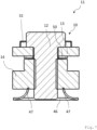
- FIG 3 shows a view of a section through the connection system 10 according to Figure 1 in a state connecting two elements 34, 36.
- the nut 14 is first inserted into the receiving space 44 of the cage 16.
- the cage 16 can be handled with the nut 14 received therein by means of the two projections 32 from one side of an element 34, 36 to be connected.
- the cage 16 with the held by the nut 14 from the same side of an element 34,36 to be connected and the screw 12 is screwed into the nut 14.
- the elements 34, 36 are connected to one another by means of the connection system 10.
- the screw 12 By turning the screw 12, it is screwed into the internal thread of the screw channel 17 arranged in the nut 14.
- the nut 14 moves in the direction of the screw head (i.e. Fig. 3 upwards).
- the upper side 21 of the foot section 22 protruding from the receiving space 44 presses against the second element 36 and presses this against the first element 34.
- the first element 34 is in turn pushed by the washer 13 in the opposite direction (i.e. in Fig. 3 downwards).
- the two elements 34, 36 are clamped between the base section 22 of the nut 14 and the washer 13.
- Figure 4 shows a view of a plane perpendicular to the section in Figure 3 arranged section through the connection system 10 according to Figure 1 in a state connecting two elements 34,36.
- the shear forces are transmitted in addition to the head section 20 also at least partially absorbed by the casing section 30. This leads to further relief of the screw 12.
- Figure 5 shows a perspective view of an arrangement 11 according to the invention. Shown is a first element 34 which is designed in the form of a substantially triangular angle element and a second element 36 which is designed in the form of an angular profile.
- the second element 36 in this case has a plurality of holes 38.
- the holes 38 have a shape that corresponds to the shape of the base section 46 and the nut 14 when the nut 14 is received in the cage 16 or the receiving space 44.
- the connection system 10 can be pushed through such a hole 38.
- the connection system can be pushed through such a hole 38, wherein pushing through in an orientation rotated by 90° is preferably blocked due to the shape of the hole 38. If the connection system 10 is rotated, for example, by 90° about the screw axis 15 after it has been pushed through the hole 38, the sections of the foot section 22 of the nut 14 that protrude from the cage 16 or the receiving space 44 prevent the connection system 10 from being pulled out of the hole 38. In this rotated state, the connection system 10 can connect two elements to one another (cf. Figure 4 ).
- the first element 34 has a first elongated hole 40.
- the first elongated hole 40 has two long sides 42.
- the distance between the two long sides 42 of the first elongated hole 40 corresponds to the diameter and thus the widest point of the base section 46 of the cage 16. This allows the Connection system 10 can be moved along the first elongated hole 40.
- the connection system 10 can also be moved along the elongated hole 40 after rotation about the screw axis 15, since the distance between the two sides 42 is correspondingly large.
- the first element 34 has a second elongated hole 52.
- the second elongated hole has two longitudinal sides 54, wherein in this case a plurality of points 56 are arranged along the second elongated hole 52, at which the distance between the longitudinal sides 54 corresponds to the diameter and thus the widest point of the base section 46 of the cage 16.
- the distance between the longitudinal sides 54 is greatest at these points. Accordingly, at other points of the second elongated hole 52, the distance between the longitudinal sides 54 is smaller.
- the connection system 10 can only be inserted into and removed from the second elongated hole 52 at points 56 (in particular those with a large distance between the longitudinal sides 54).
- the minimum distance between the longitudinal sides 54 corresponds in particular to the width of the head section 20 of the nut 14 and, if applicable, of the surrounding cage.
- connection system 10 with the nut 14 accommodated in the cage 16 can be pushed through the second elongated hole 52.
- the connection system 10 is blocked against displacement along the second elongated hole 52.
- the outer shape of the casing section 30 corresponds to the shape of the base section 46, so that, with the exception of the openings 28, the casing section 30 has a has a circular cylindrical outer shape. This blocks any displacement along the second elongated hole 52.
- the cage 16 with its shell section 30 is rotated around the screw axis 15 such that the openings 28 of the shell section 30 are arranged along the longitudinal sides 54.
- the circular cylindrical shape of the outer shape of the shell section 30 is interrupted by the openings 28. Due to the openings 28 in the shell section 30, the cage 16 has a smaller extension in this orientation, which can correspond to the minimum distance between the longitudinal sides 54.
- the Figure 5 The example shown represents a state in which the connection system 10 can be moved along the elongated hole 52.
- Figure 6 shows a further embodiment of the connection system 10.
- the base section 46 is elongated and has two resilient elements 47. These are arranged on opposite sides of the base section 46 (at the two ends of the long side of the base section 46) and protrude radially inward and upward from the base section 46 with respect to the screw axis 15, i.e. into the receiving space 44.
- the resilient elements 47 represent, in particular, resilient projections of the base section 46.
- the resilient elements 47 are designed in the manner of spring tabs or leaf springs.
- the two resilient elements 47 are generally designed such that they preload the nut 14 in the direction of the screw 12 when the connection system 10 is in the assembled state, i.e. when the nut 14 is received in the cage 16.
- the spring elements 47 push the nut 14 upwards, towards the screw head.
- Figure 7 shows a view of a section through the connection system 10 according to Figure 6 .
- the assembled state of the connection system 10 is shown here.
- the resilient elements 47 press the nut 14 toward the screw head (in particular, away from the base section 46).
- the nut 14 is pressed against the cover section 50 with the top side 21 of the head section 20.
- the two resilient elements 47 can be formed integrally with the base section 46. In other words, the resilient elements 47 can be part of the base section 46.
- Figure 8 shows a view of a section through a connection system 10 in which the resilient elements 47 do not project towards the central longitudinal axis (i.e. into the receiving space 44, radially inwards), but radially outwards (i.e. away from the central longitudinal axis or from the receiving space 44).
Landscapes
- Engineering & Computer Science (AREA)
- General Engineering & Computer Science (AREA)
- Mechanical Engineering (AREA)
- Connection Of Plates (AREA)
- Bolts, Nuts, And Washers (AREA)
Description
- Die Erfindung betrifft ein Verbindungssystem zum Verbinden von mindestens zwei, insbesondere plattenartigen, Bauteilen mit den Merkmalen des Oberbegriffs des Anspruchs 1 und eine Anordnung mit Merkmalen des nebengeordneten Anspruchs.
- Es sind verschiedene Verbindungs- und Befestigungssysteme bekannt. Dabei kann es erwünscht sein, eine Schraubverbindung umfassend eine Schraube und eine zugehörige Mutter so auszugestalten, dass diese zwei Elemente miteinander verbindet und dazu lediglich von einer Seite aus zugegriffen werden muss. Dies ist vor allem dann wünschenswert, wenn es schwierig ist, Werkzeug an die Mutter anzulegen, weil nicht ausreichend Platz hierzu zur Verfügung steht. Solche Verbindungssysteme kommen z. B. bei der Montage von Metallprofilen aneinander zum Einsatz oder beim Aufbau von Krangerüsten.
- So beschreibt z. B. die
DE 10 2017 116 858 A1 ein Befestigungselement für eine Befestigung an einer Montageschiene mit einer Hammerkopfschraube, die in einem U-förmigen Clip untergebracht ist, so dass die Hammerkopfschraube um eine Achse geschwenkt werden kann. -
DE 10 2017 116 856 A1 schlägt eine rechteckige rohrförmige Montageschiene mit einem Hammerkopfbolzen als Befestigungselement vor. Dabei sind die Montageschienen mit Vertiefungen ausgebildet, die sich in Längsrichtung erstrecken und in denen ein scheibenförmiges Widerlager des Befestigungselements versenkbar ist, das auf einem Schaft einer Schraube des Befestigungselements angeordnet ist. -
US 2 681 679 A ,US 3 785 421 A ,DE 69 48 314 U ,FR 2 241 213 A5 US 2018 / 266 476 A1 zeigen jeweils ein Verbindungssystem mit Merkmalen des Anspruchs 1. - Die Aufgabe der Erfindung ist es, ein Verbindungssystem zum Verbinden zweier insbesondere plattenartiger Elemente bzw. Bauteile bereitzustellen, welches von einer Seite aus komfortabel befestigbar ist.
- Diese Aufgabe wird durch ein Verbindungssystem mit den Merkmalen des Anspruchs 1 gelöst. Das Verbindungssystem umfasste eine Schraube und eine mit der Schraube korrespondierende Mutter. Die Mutter weist einen Schraubkanal auf, der sich entlang einer Schraubachse erstreckt. In diesen Schraubkanal lässt sich die Schraube einschrauben. Der Schraubkanal weist vorzugsweise zumindest Abschnittsweise ein Innengewinde auf. Dadurch kann z.B. eine gewöhnliche Schraube eingedreht werden.
- Das Verbindungssystem umfasst weiter einen Käfig zur Aufnahme der Mutter. Dieser Käfig dient dazu, die Mutter beim Einschrauben der Schraube zu halten, insbesondere ohne dass die Mutter mit einem Schraubschlüssel gegengehalten werden muss.
- Die Mutter weist eine spezielle Formgebung auf, mit einem Fußabschnitt und einen sich entlang der Schraubachse anschließenden Kopfabschnitt. Dabei steht der Fußabschnitt zumindest abschnittsweise in Richtung senkrecht zur Schraubachse über den Kopfabschnitt über. Mit anderen Worten weist der Fußabschnitt entlang der Schraubachse betrachtet eine größere Querschnittsfläche auf, als der Kopfabschnitt. Die Mutter kann insofern als eine Hammerkopfmutter ausgestaltet sein, wobei der Fußabschnitt den Kopfabschnitt hammerartig überragt.
- Die genannte Ausgestaltung ermöglicht es, dass der Kopfabschnitt der Mutter durch die aneinander zu befestigenden Elemente bzw. Bauteile durchgeführt wird und der Fußabschnitt an einem der Elemente bzw. Bauteile anliegt. Durch Eindrehen der Schraube werden dann die zu befestigenden Elemente/Bauteile aneinander gepresst, wobei lateral wirkende Kräfte von dem Kopfabschnitt der Mutter aufgenommen werden. Da die Mutter beim Eindrehen der Schraube in dem Käfig aufgenommen ist, kann eine einfache Handhabung von einer Seite aus erfolgen, insbesondere ohne Gegenfixierung der Mutter mit einem Schraubschlüssel.
- Vorzugsweise gehen der Fußabschnitt und der Kopfabschnitt der Mutter stufenförmig ineinander über. Insbesondere bilden der Fußabschnitt und der Kopfabschnitt zusammen eine Stufe aus. Insofern kann zwischen Fußabschnitt und Kopfabschnitt eine Innenkante verlaufen, in welcher eine Mantelfläche des Kopfabschnitts im Wesentlichen rechtwinklig auf eine Oberfläche des Fußabschnitts stößt.
- Vorzugsweise verläuft der Schraubkanal durch den Kopfabschnitt und durch den Fußabschnitt. Der Schraubkanal kann insbesondere als Durchgangsöffnung durch Kopfabschnitt und Fußabschnitt ausgebildet sein. Mit anderen Worten, der Schaubkanal verläuft insbesondere zumindest durch den Kopfabschnitt der Mutter, so dass die Schraube in die Mutter und insbesondere in den Kopfabschnitt der Mutter eingedreht werden kann. Eine Durchgangsöffnung erlaubt die Verwendung von Schrauben mit unterschiedlichen Längen.
- Vorteilhaft kann sein, dass der Kopfabschnitt und/oder der Fußabschnitt eine Oberseite aufweist, welche sich insbesondere im Wesentlichen senkrecht zur Schraubachse erstreckt, wobei die Oberseite eben, insbesondere glatt, ausgebildet ist. Mit glatt ist im Sinne der vorliegenden Anmeldung gemeint, dass die Oberseite insbesondere keine Riffelungen aufweist. Diese konstruktive Maßnahme kann bei dem beschriebenen Verbindungssystem eingespart werden, da lateral zur Schraubachse wirkende Kräfte weitgehend von der Mutter (insbesondere Kopfabschnitt) aufgenommen werden.
- Insbesondere ist die Oberseite des Kopfabschnitts und oder des Fußabschnitts senkrecht zur Schraubachse angeordnet.
- Erfindungsgemäß ist die Oberseite des Fußabschnitts dazu ausgebildet, an eine Oberfläche der zu verbindenden Elemente anzuliegen und diese aneinander zu pressen.
- Der Käfig weist einen Bodenabschnitt sowie einen an den Bodenabschnitt angrenzenden Mantelabschnitt auf. Der Käfig begrenzt einen Aufnahmeraum für die Mutter. Der Mantelabschnitt weist wenigstens einen Durchbruch auf, durch welchen die Mutter zumindest teilweise in den Aufnahmeraum einschiebbar ist. Der Bodenabschnitt des Käfigs kann eben ausgestaltet sein, Erhebungen und/oder Vertiefungen aufweisen und/oder z. b. geriffelt ausgestaltet sein, um ein Herausrutschen der Mutter zu verhindern.
- Der Käfig weist einen Deckelabschnitt auf, wobei der Deckelabschnitt an den Mantelabschnitt angrenzt und beabstandet zum Bodenabschnitt angeordnet ist. Auch hier ist es analog zum Bodenabschnitt denkbar, dass der Deckelabschnitt des Käfigs eben ausgestaltet sein kann, Erhebungen und/oder Vertiefungen aufweisen kann und/oder z. b. geriffelt ausgestaltet sein kann, um ein Herausrutschen der Mutter zu verhindern. Durch den Deckelabschnitt wird die Mutter weitgehend in dem Käfig stabilisiert, sodass die Schraube komfortabel eingedreht werden kann.
- Es ist eine Schrauböffnung zum Durchführen der Schraube in dem Bodenabschnitt und/oder dem Deckelabschnitt vorgesehen. Dabei kann die Schrauböffnung des Bodenabschnitts und die Schrauböffnung des Deckelabschnitts die gleiche Form und/oder Größe aufweisen. Es ist ebenso denkbar, dass die Schrauböffnung des Bodenabschnitts und die Schrauböffnung des Deckelabschnitts unterschiedliche Form und/oder Größe aufweisen, da die Schrauböffnung nicht zwingend eine Führungsfunktion für die Schraube bereitstellen muss.
- Der Käfig und die Mutter sind derart ausgebildet, dass die Mutter in Richtung senkrecht zur Schraubachse durch den Durchbruch des Mantelabschnitts in den Aufnahmeraum derart einschiebbar ist, dass der Schraubkanal mit der Schrauböffnung des Bodenabschnitts und/oder der Schrauböffnung des Deckelabschnitts fluchtet. Zum Verbinden kann dann die Schraube durch die Schrauböffnung des Deckelabschnitts in den Schraubkanal der Mutter eingedreht werden. Dabei wird die Schraube bzw. die Mutter weitgehend fixiert, so dass ein unbeabsichtigtes Herausfallen aus dem Käfig verhindert werden kann.
- Bevorzugterweise ist, wenn die Mutter in den Aufnahmeraum eingeschoben ist, der Kopfabschnitt vollständig in dem Aufnahmeraum aufgenommen. Dabei kann der Fußabschnitt den Aufnahmeraum durch den Durchbruch des Mantelabschnitts hindurch zumindest teilweise überragen.
- Vorteilhaft kann sein, dass der Mantelabschnitt des Käfigs mindestens eine dem Aufnahmeraum zugewandte Innenfläche, insbesondere zwei gegenüberliegende Innenflächen, aufweist. Die Innenfläche kann eine Anlagefläche für eine Seitenfläche des Fußabschnitts und/oder eine Seitenfläche des Kopfabschnitts derart bereitstellen, dass dann, wenn die Mutter in den Aufnahmeraum eingeschoben ist, die Mutter gegen ein Verdrehen um die Schraubachse fixiert ist. Insbesondere kann die Anlagefläche eben ausgestaltet sein, Erhebungen und/oder Vertiefungen aufweisen und/oder z. b. geriffelt ausgestaltet sein, um ein Herausrutschen der Mutter zu verhindern.
- Die Mutter weist insbesondere zwei gegenüberliegende, ebene Flächen auf. Insbesondere liegen die Seitenfläche des Kopfabschnitts und die Seitenfläche des Fußabschnitts in einer Ebene. Die Mutter ist insofern weiter vorzugsweise an zwei gegenüberliegenden Seiten eben ausgestaltet (je eine der ebenen Flächen umfasst dann eine der genannten Seitenflächen des Fußabschnitts und die daran anschließende Seitenfläche des Kopfabschnitts).
- Der Fußabschnitt der Mutter steht insbesondere an zwei gegenüberliegenden Enden über den Kopfabschnitt über, verläuft aber zwischen den beiden überstehenden Bereichen bündig mit dem Kopfabschnitt (derart, dass die ebene Fläche an der Seite der Mutter ausgebildet ist). Allgemein gesprochen sind Kopfabschnitt und Fußabschnitt in Projektion der Schraubachse betrachtet vorzugsweise gleich breit, aber der Fußabschnitt ist länger, als der Kopfabschnitt und überragt den Kopfabschnitt daher.
- Vorzugsweise weist der Käfig eine zylindrische, insbesondere eine kreiszylindrische Außenform auf. Dadurch kann der Käfig in einen Durchbruch in den zu verbindenden Elementen eigeschoben werden bzw. durchgesteckt werden.
- Der Bodenabschnitt und/oder der Deckelabschnitt können sich z.B. eben erstrecken und einen runden, insbesondere kreisförmigen, Außenumfang aufweisen.
- Zur weiteren Ausgestaltung ist denkbar, dass in Projektion entlang der Schraubachse betrachtet, der Bodenabschnitt größer ist, als der Deckelabschnitt. Insbesondere in Projektion entlang der Schraubachse betrachtet kann der Bodenabschnitt den Deckelabschnitt im Bereich des Durchbruchs überragen. Mit anderen Worten: In der Draufsicht auf das Verbindungssystem kann der Deckelabschnitt und teilweise der Bodenabschnitt des Verbindungssystems sichtbar sein. In der Ansicht von unten auf das Verbindungssystem kann nur der Bodenabschnitt sichtbar sein. Dies ermöglicht es, den Käfig mit seinem Bodenabschnitt durch entsprechende Löcher bzw. Langlöcher in den zu verbindenden Bauteilen zu stecken, wobei dann aufgrund des geringeren Durchmessers des Deckelabschnitts der Käfig trotzdem noch verdreht und/oder in einem Langloch verschoben werden kann.
- Vorzugsweise sind an dem Käfig mindestens zwei Vorsprünge vorgesehen, z.B. in der Art von überstehenden Flügeln bzw. Laschen. Die Vorsprünge sind insbesondere an dem Mantelabschnitt des Käfigs und/oder dem Deckelabschnitt des Käfigs angeordnet und erstrecken sich im zusammengeschraubten Zustand insbesondere von der Schraubachse weg und sind insbesondere rotationssymmetrisch und/oder einander gegenüberliegend bezüglich der Schraubachse angeordnet. Vorzugsweise sind genau zwei Vorsprünge vorgesehen, die auf gegenüberliegenden Seiten des Käfigs angeordnet sind. Damit lassen sich die Vorsprünge und damit der Käfig mit einem Griff mit zwei Fingern handhaben. Weiter bevorzugt können drei Vorsprünge an dem Käfig angeordnet sein, so dass mit einem Griff mit drei Fingern der Käfig handhabbar ist. Der Griff mit drei Fingern ist besonders stabil und angenehm für die Handhabung. Insbesondere kann der Abstand zwischen den Vorsprüngen gleich sein.
- Vorzugsweise ist an dem Bodenabschnitt mindestens ein federndes Element vorgesehen. Dabei kann das federnde Element die Mutter, insbesondere den Fußabschnitt, im zusammengesetzten Zustand des Verbindungssystems vom Bodenabschnitt wegdrücken. Mit anderen Worten, das federnde Element drückt die Mutter vom Bodenabschnitt weg in Richtung der Schraube bzw. in Richtung eines gegebenenfalls vorhandenen Deckelabschnitts. Damit wird die Mutter im zusammengesetzten Zustand gegen den Schraubenkopf, insbesondere entlang der Schraubachse, vorgespannt. Das federnde Element kann in den Aufnahmeraum des Käfigs hineinragen, oder derart ausgestaltet sein, dass es vom Aufnahmeraum bzw. Mantelabschnitt wegragt.
- Das federnde Element kann sich vom Bodenabschnitt und/oder Mantelabschnitt flügelartig nach radial außen, also radial von der Schraubachse weg, erstrecken. Es ist aber ebenso denkbar, dass das federnde Element sich nach radial innen, also radial zu der Schraubachse hin, erstreckt.
- Besonders vorteilhaft sind zwei federnde Elemente vorgesehen, die insbesondere auf sich gegenüberliegenden Seiten des Bodenabschnitts angeordnet sind.
- Die zu lösende Aufgabe wird weiter durch die erfindungsgemäße Anordnung mit den Merkmalen des nebengeordneten Anspruchs gelöst. Die Anordnung stellt insofern einen Bausatz dar und umfasst ein Verbindungssystem mit oben beschriebenen Merkmalen, ein erstes insbesondere plattenartiges Element bzw. Bauteil und ein zweites insbesondere plattenartiges Element bzw. Bauteil, wobei das erste Element und das zweite Element jeweils mindestens ein Loch aufweisen.
- Dabei weist das Loch eine der Mutter und/oder dem Bodenabschnitt des Käfigs entsprechende Form auf, so dass der Käfig mit aufgenommener Mutter in das Loch einführbar ist.
- Zur weiteren Ausgestaltung weist das erste Element und/oder das zweite Element ein erstes Langloch mit zwei Längsseiten auf. Der Abstand zwischen den Längsseiten kann dem Bodenabschnitt des Käfigs entsprechen, so dass der Käfig mit aufgenommener Mutter in das Langloch einführbar und das Verbindungssystem entlang des Langlochs bewegbar ist. Dabei ist das Bewegen des Verbindungssystems entlang des ersten Langlochs unabhängig von einem Verdrehen des Verbindungssystems um die Schraubachse möglich.
- Vorteilhafterweise weist das erste Element und/oder das zweite Element ein zweites Langloch mit zwei Längsseiten auf, wobei das zweite Langloch an mindestens einer Stelle eine dem Bodenabschnitt des Käfigs entsprechende Form aufweist. An dieser Stelle kann der Abstand zwischen den beiden Längsseiten größer sein, als an einer anderen Stelle des zweiten Langlochs, so dass das Bewegen des Verbindungssystems entlang des Langlochs, insbesondere durch eine Drehung des Käfigs um 90° um die Schraubachse, blockierbar ist. Das Verbindungssystem kann nur an diesen Stellen in das zweite Langloch eingeführt und wieder herausgezogen werden.
- Vorteilhafterweise ist das Verbindungssystem und die beiden Elemente derart ausgebildet, dass das erste und das zweite Element zwischen Mutter und Käfig positioniert werden können, so dass der Käfig in Verbindung mit der Mutter die beiden Elemente umschließt. Die beiden Elemente können so durch Käfig und Mutter, beispielsweise als Montagehilfe, zusammengehalten bzw. zusammengedrückt werden.
- Weitere Merkmale, Einzelheiten und Vorteile der Erfindung ergeben sich aus dem Wortlaut der Ansprüche sowie aus der folgenden Beschreibung von Ausführungsbeispielen anhand der Zeichnungen. Es zeigen:
- Fig. 1
- eine perspektivische Ansicht auf ein Verbindungssystem in einem auseinander genommenen Zustand;
- Fig. 2
- eine perspektivische Ansicht auf das Verbindungssystem gemäß
Figur 1 in einem zusammengesetzten Zustand; - Fig. 3
- eine Ansicht auf einen Schnitt durch das Verbindungssystem gemäß
Figur 1 in einem zwei Elemente verbindenden Zustand; - Fig. 4
- eine Ansicht auf einen senkrecht zum Schnitt in
Figur 3 angeordneten Schnitt durch das Verbindungssystem gemäßFigur 1 in einem zwei Elemente verbindenden Zustand; - Fig. 5
- eine perspektivische Ansicht auf eine erfindungsgemäße Anordnung;
- Fig. 6
- ein weiteres Ausführungsbeispiel eines Verbindungssystems;
- Fig. 7
- eine Ansicht auf einen Schnitt durch das Verbindungssystem gemäß
Figur 6 und - Fig. 8
- eine Ansicht auf einen Schnitt durch ein weiteres Ausführungsbeispiel des Verbindungssystems.
- In der nachfolgenden Beschreibung sowie in den Figuren tragen sich entsprechende Bauteile und Elemente gleiche Bezugszeichen. Zur besseren Übersichtlichkeit sind nicht in allen Figuren sämtliche Bezugszeichen wiedergegeben.
-
Figur 1 zeigt eine perspektivische Ansicht auf ein erfindungsgemäßes Verbindungssystem 10 in einem auseinander genommenen Zustand. Das Verbindungssystem 10 umfasst eine Schraube 12 und eine Mutter 14. Die Schraube 12 ist nur schematisch und ohne ein Außengewinde dargestellt. Die Mutter 14 weist, einen Schraubkanal 17 auf, der vorliegend als Durchgangsöffnung ausgebildet ist und der sich entlang einer Schraubachse 15 erstreckt. Die Schraubachse 15 ist inFig. 1 durch eine gestrichelte Linie dargestellt. Der Schraubkanal 17 weist ein nicht dargestelltes Innengewinde auf, welches mit dem ebenfalls nicht dargestellten Außengewinde der Schraube 12 korrespondiert, sodass die Schraube 12 in den Schraubkanal 17 der Mutter 14 einschraubbar ist. - Die Mutter 14 weist einen Fußabschnitt 22 und einen entlang der Schraubachse 15 an den Fußabschnitt 22 angrenzenden Kopfabschnitt 20 auf. Die Mutter 14 ist vorliegend einstückig ausgestaltet. Es ist jedoch denkbar die Mutter 14 aus mehreren Elementen bestehend auszugestalten. So kann beispielsweise der Kopfabschnitt 20 der Mutter 14 einstückig und den Fußabschnitt 22 der Mutter 14 einstückig ausgestaltet sein.
- Der Fußabschnitt 22 geht vorliegend stufenförmig in den Kopfabschnitt 20 über. Der Flussabschnitt 22 überragt den Kopfabschnitt an zwei sich gegenüberliegenden Seiten des Kopf- bzw. Fußabschnittes 20, 22, so dass auf diesen sich gegenüberliegenden Seiten jeweils eine Stufenform gebildet wird.
- Der Kopfabschnitt 20 weist eine Seitenfläche 19 auf und der Fußabschnitt 22 weist eine Seitenfläche 18 auf. Vorliegend sind diese beiden Flächen als eine gemeinsame ebene Seitenfläche ausgebildet.
- Der Kopfabschnitt 20 weist eine senkrecht zur Schraubachse 15 angeordnete Oberseite 21 auf, die vorliegend eben ausgebildet ist. Auch der Fußabschnitt 22 weist eine senkrecht zur Schraubachse 15 angeordnete Oberfläche 21 auf, d. h. parallel zur Oberseite 21 des Kopfabschnittes 20. Die Oberseite 21 des Fußabschnittes ist ebenfalls eben ausgebildet. Insbesondere weisen die Oberseiten 21 keine Riffelungen auf, da lateral (entlang der Oberflächen der zu befestigenden Elemente wirkende) Kräfte durch den Kopfabschnitt 20 aufgenommen werden.
- Der Kopfabschnitt 20 weist an zwei sich gegenüberliegenden Seiten, an denen der Fußabschnitt 22 und der Kopfabschnitt 20 eine Stufenform bilden, eine im Wesentlichen runde Außenform auf.
- Der Fußabschnitt 22 und der Kopfabschnitt 20 weisen in Projektion entlang der Schraubachse 15 betrachtet jeweils eine Breite und eine Länge auf. Vorzugsweise ist die Breite des Fußabschnitts 22 im Wesentlichen gleich der Breite des Kopfabschnitts, so dass die Mutter 14 eine insgesamt im Wesentlichen ebene Seitenfläche aufweist. Der Fußabschnitt 22 ist aber vorzugsweise länger, als der Kopfabschnitt 20, so dass der Fußabschnitt 22 zumindest abschnittsweise in Richtung senkrecht zur Schraubachse 15 über den Kopfabschnitt 20 übersteht. Zur weiteren Ausgestaltung können Länge und Breite des Kopfabschnitts 20 im Wesentlichen gleich groß sein. Bei dem Fußabschnitt 22 ist jedoch vorzugsweise die Länge größer, als die Breite. Insbesondere ist der Fußabschnitt 22 in Projektion entlang der Schraubachse 15 betrachtet im Wesentlichen rechteckig.
- Das Verbindungssystem 10 weist weiter einen Käfig 16 auf. Der Käfig 16 hat vorliegend einen Bodenabschnitt 46, einen sich daran angrenzenden Mantelabschnitt 30 und einen sich an den Mantelabschnitt 30 angrenzenden Deckelabschnitt 50. Der Bodenabschnitt 46 ist flach bzw. plattenförmig ausgebildet, weist eine Schrauböffnung 48 und eine kreisförmige Außenform auf. Auch der Deckelabschnitt 50 ist flach bzw. plattenförmig ausgebildet und weist eine Schrauböffnung 48 auf, die vorliegend die gleiche Größe und Form wie die Schrauböffnung 48 des Bodenabschnitt 46 aufweist. Der Deckelabschnitt 50 weist im Wesentlichen eine runde Außenform auf.
- An dem Deckelabschnitt 50 sind an zwei sich gegenüberliegenden Seiten Vorsprünge 32 angeordnet. Vorliegend sind die Vorsprünge 32 kragenartig bzw. flügelartig ausgebildet und erstrecken sich vom Deckelabschnitt 50 nach radial außen.
- Der Käfig 16 bildet einen Aufnahmeraum 44 für die Mutter 14. vorliegend wird der Aufnahmeraum 44 den Bodenabschnitt 46, den Mantelabschnitt 30 und den Deckelabschnitt 50 begrenzt.
- Der Mantelabschnitt 30 weist zwei Durchbrüche 28 auf, die auf gegenüberliegenden Seiten des Mantelabschnitts 30 angeordnet sind. Durch diese Durchbrüche 28 kann die Mutter 14 in den Käfig 16 und somit in den für die Mutter 14 bestimmten Aufnahmeraum 44 eingeschoben werden.
- Vorliegend sind zwei gegenüberliegende Seiten des Mantelabschnitts 30 an deren Innenfläche 45, d. h. dem Aufnahmeraum 44 zugewandten Flächen, eben ausgebildet. Diese Innflächen 45 sind derart ausgebildet, dass die Mutter 14, wenn sie in den Käfig 16 eingeschoben wird, mit den Seitenflächen 18 und 19 an den Innenflächen 45 aufliegt. Damit ist die Mutter 14 gegenüber einem Verdrehen um die Schraubachse 15 in Bezug auf den Käfig 16 fixiert. Somit kann der Käfig 16 samt der aufgenommenen Mutter 14 über die zwei Vorsprünge 32 sicher gedreht und gehandhabt werden.
- Im dargestellten Beispiel ist eine Unterlegscheibe 13 dargestellt. Zum zusammensetzten des Verbindungssystems 10 wird die Mutter 14 durch einen der zwei Durchbrüche 28 in den Aufnahmeraum 44 eingeschoben, sodass die Schrauböffnungen 48 des Bodenabschnitts 46 und des Deckelabschnitts 50 fluchtend mit dem Schraubkanal 17 zusammenliegen. Sobald die Mutter 14 im Käfig 16 bzw. dessen Aufnahmeraum 44 aufgenommen ist, kann das Verbindungssystem an den Fortsätzen 32 gehandhabt werden. Danach wird die Schraube 12 ggf. zunächst durch die Unterlegscheibe 13, dann durch die Schrauböffnung 48 des Deckelabschnitts 50, durch den Schraubkanal 17 der Mutter 14, und anschließend durch die Schrauböffnung 48 des Bodenabschnitt 46 hindurchgesteckt bzw. geschraubt.
-
Figur 2 zeigt eine perspektivische Ansicht auf das Verbindungssystem 10 gemäßFigur 1 in einem zusammengesetzten Zustand. In diesem Zustand ist die Mutter 14 im Käfig 16 bzw. dem Aufnahmeraum 44 aufgenommen. Der Fußabschnitt 22 ragt an zwei sich gegenüberliegenden Seiten aus dem Aufnahmeraum 44 bzw. aus dem Käfig 16 durch dich Durchbrüche 28 heraus. Der Kopfabschnitt 20 der Mutter 14 ist im Wesentlichen innerhalb des Aufnahmeraum 44 angeordnet. Im dargestellten Beispiel sind die beiden Vorsprünge 32 entlang der Schraubachse 15 betrachtet senkrecht zu den Durchgangsrichtungen der Durchbrüche 28 angeordnet. -
Figur 3 zeigt eine Ansicht auf einen Schnitt durch das Verbindungssystem 10 gemäßFigur 1 in einem zwei Elemente 34,36 verbindenden Zustand. Zum verbindenden zweier Elemente 34,36 wird zunächst die Mutter 14 in den Aufnahmeraum 44 des Käfig 16 eingeschoben. Der Käfig 16 lässt sich mit der darin aufgenommenen Mutter 14 mittels der beiden Vorsprünge 32 von einer Seite eines zu verbindenden Elements 34,36 handhaben. Mit anderen Worten kann der Käfig 16 mit der darin aufgenommenen Mutter 14 von derselben Seite eines zu verbindenden Elements 34,36 festgehalten und die Schraube 12 in die Mutter 14 eingeschraubt werden. - Die als Platten ausgebildeten Elemente 34,36 werden mittels des Verbindungssystems 10 miteinander verbunden. Durch Drehung der Schraube 12 wird diese in das Innengewinde des in der Mutter 14 angeordneten Schraubkanals 17 eingeschraubt. Dadurch bewegt sich die Mutter 14 in Richtung des Schraubenkopfes (also in
Fig. 3 nach oben). Dabei drückt die Oberseite 21 des aus dem Aufnahmeraum 44 herausragenden Fußabschnitts 22 gegen das zweite Element 36 und drückt dieses gegen das erste Element 34. Das erste Element 34 wird wiederum durch die Unterlegscheibe 13 in die entgegengesetzte Richtung (also inFig. 3 nach unten) gedrückt. Somit werden die beiden Elemente 34,36 zwischen dem Fußabschnitt 22 der Mutter 14 und der Unterlegscheibe 13 eingeklemmt. Selbstverständlich ist hierbei jeweils die Relativbewegung gemeint. - Mögliche Scherkräfte zwischen den beiden Elementen 34 und 36 werden durch den Kopfabschnitt 20 der Mutter 14 aufgefangen. Dies entlastet die Schraube bzw. verhindert eine Übertragung der Scherkräfte zwischen den beiden Elementen 34 und 36 auf die Schraube 12, die sonst die schwächste Stelle einer Schraubverbindung darstellen kann.
-
Figur 4 zeigt eine Ansicht auf einen senkrecht zum Schnitt inFigur 3 angeordneten Schnitt durch das Verbindungssystem 10 gemäßFigur 1 in einem zwei Elemente 34,36 verbindenden Zustand. In der dargestellten Orientierung werden die Scherkräfte zusätzlich zum Kopfabschnitt 20 auch zumindest teilweise vom Mantelabschnitt 30 aufgefangen. Was zu einer weiteren Entlastung der Schraube 12 führt. -
Figur 5 zeigt eine perspektivische Ansicht auf eine erfindungsgemäße Anordnung 11. Dargestellt ist ein erstes Element 34, dass in Form eines im Wesentlichen dreieckigen Winkelelements ausgestaltet ist und ein zweites Element 36, dass in Form eines eckigen Profils ausgestaltet ist. - Das zweite Element 36 weist vorliegend mehrere Löcher 38 auf. Die Löcher 38 weisen eine Form auf, die der Form des Bodenabschnitt 46 und der Mutter 14 entspricht, wenn die Mutter 14 in dem Käfig 16 bzw. dem Aufnahmeraum 44 aufgenommen ist. So kann das Verbindungssystem 10 durch ein solches Loch 38 durchgesteckt werden. In einer Orientierung kann das Verbindungssystem durch ein derartiges Loch 38 hindurchgesteckt werden, wobei ein Durchstecken in einer um 90° gedrehten Orientierung vorzugsweise aufgrund der Form des Lochs 38 blockiert ist. Dreht man das Verbindungssystem 10, nachdem es durch das Loch 38 hindurchgesteckt wurde um beispielsweise 90° um die Schraubachse 15, so verhindern die aus dem Käfig 16 bzw. dem Aufnahmeraum 44 herausragenden Abschnitte des Fußabschnitts 22 der Mutter 14 das Herausziehen des Verbindungssystems 10 aus dem Loch 38. In diesem verdrehten Zustand kann das Verbindungssystem 10 zwei Elemente miteinander verbinden (vgl.
Figur 4 ). - Das erste Element 34 weist ein erstes Langloch 40 auf. Das erste Langloch 40 hat zwei Längsseiten 42. Dabei entspricht der Abstand zwischen den beiden Längsseiten 42 des ersten Langlochs 40 dem Durchmesser und somit der breitesten Stelle des Bodenabschnitts 46 des Käfigs 16. Damit kann das Verbindungssystem 10 entlang des ersten Langloch 40 verschoben werden. Wenn das Verbindungssystem 10 durch das erste Langloch 40 hindurchgesteckt ist, so kann das Verbindungssystem 10 auch nach einer Drehung um die Schraubachse 15 entlang des Langloch 40 verschoben werden, da der Abstand zwischen den beiden Seiten 42 entsprechend groß ist.
- Des Weiteren weist das erste Element 34 ein zweites Langloch 52 auf. Das zweite Langloch weist zwei Längsseiten 54 auf, wobei entlang des zweiten Langloch 52 vorliegend mehrere Stellen 56 angeordnet sind, an denen der Abstand zwischen den Längsseiten 54 dem Durchmesser und somit der breitesten Stelle des Bodenabschnitts 46 des Käfigs 16 entsprechen. Der Abstand zwischen den Längsseiten 54 ist an diesen Stellen am größten. Insofern ist an anderen Stellen des zweiten Langlochs 52 der Abstand zwischen den Längsseiten 54 geringer. Nur an den Stellen 56 (insbesondere die mit großem Abstand zwischen den Längsseiten 54) kann das Verbindungssystem 10 in das zweite Langloch 52 hineingesteckt und wieder herausgezogen werden. Der minimale Abstand zwischen den Längsseiten 54 entspricht insbesondere der Breite des Kopfabschnitts 20 der Mutter 14 und ggf. des umgebenden Käfigs.
- Somit kann das Verbindungssystem 10 mit der im Käfig 16 aufgenommenen Mutter 14 durch das zweite Langloch 52 durchgesteckt werden kann. Nach dem Durchstecken des Verbindungssystems 10 durch das zweite Langloch 54 an einer der Stellen 56 ist das Verbindungssystem 10 gegen ein Verschieben entlang des zweiten Langlochs 52 blockiert. Der Mantelabschnitt 30 weist an seiner Außenform eine dem Bodenabschnitt 46 entsprechende Form auf, so dass, die Durchbrüche 28 ausgenommen, der Mantelabschnitt 30 eine kreiszylindrische Außenform aufweist. Dies bewirkt das Blockieren einer Verschiebung entlang des zweiten Langloch 52.
- Durch eine Drehung um 90° um die Schraubachse 15 kann ein Verschieben entlang des zweiten Langlochs 52 ermöglicht werden. Durch eine solche Drehung wird der Käfig 16 mit seinem Mantelabschnitt 30 derart um die Schraubachse 15 gedreht, dass die Durchbrüche 28 des Mantelabschnitts 30 entlang den Längsseiten 54 angeordnet sind. Der kreiszylindrische Verlauf der Außenform des Mantelabschnitts 30 wird durch die Durchbrüche 28 unterbrochen. Aufgrund der Durchbrüche 28 im Mantelabschnitt 30, weist der Käfig 16 in dieser Orientierung eine geringere Ausdehnung, die dem minimalen Abstand der Längsseiten 54 entsprechen kann. Das in
Figur 5 dargestellte Beispiel stellt einen Zustand dar in dem das Verbindungssystem 10 entlang des Langlochs 52 verschoben werden kann. -
Figur 6 zeigt ein weiteres Ausführungsbeispiel des Verbindungssystems 10. Vorliegend ist der Bodenabschnitt 46 länglich ausgestaltet und weist zwei federnde Elemente 47 auf. Diese sind an gegenüberliegenden Seiten des Bodenabschnitt 46 (an den beiden Enden der Längsseite des Bodenabschnitt 46) angeordnet und ragen bezüglich der Schraubachse 15 nach radial innen und nach oben von dem Bodenabschnitt 46 weg, also in den Aufnahmeraum 44 hinein. Die federnden Elemente 47 stellen insbesondere federnd wirkende Vorsprünge des Bodenabschnitts 46 dar. Insbesondere sind die federnden Elemente 47 in der Art von Federlaschen oder Blattfedern ausgestaltet. Die beiden federnden Elemente 47 sind allgemein derart ausgebildet, dass sie die Mutter 14 in Richtung der Schraube 12 vorspannen, wenn sich das Verbindungssystem 10 im zusammengesetzten Zustand befindet, also wenn die Mutter 14 im Käfig 16 aufgenommen ist. - Mit anderen Worten, die federnden Elemente 47 drücken die Mutter 14 nach oben, in Richtung des Schraubenkopfes.
-
Figur 7 zeigt eine Ansicht auf einen Schnitt durch das Verbindungssystem 10 gemäßFigur 6 . Vorliegend ist der zusammengesetzte Zustand des Verbindungssystem 10 dargestellt. Die federnden Elemente 47 drücken die Mutter 14 in Richtung des Schraubenkopfes (insbesondere auch von dem Bodenabschnitt 46 weg). Im dargestellten Beispiel wird die Mutter 14 mit der Oberseite 21 des Kopfabschnitts 20 an den Deckelabschnitt 50 angedrückt. Die beiden federnden Elemente 47 können einstückig mit dem Bodenabschnitt 46 ausgebildet sein. Mit anderen Worten, die federnden Elemente 47 können Teil des Bodenabschnitt 46 sein. -
Figur 8 zeigt eine Ansicht auf einen Schnitt durch ein Verbindungssystems 10, bei dem die federnden Elemente 47 nicht zur Mittellängsachse (also in den Aufnahmeraum 44 hinein, nach radial innen) ragen, sondern nach radial außen (also von der Mittellängsachse bzw. vom Aufnahmeraum 44 weg).
Claims (15)
- Verbindungssystem (10) zum Verbinden von mindestens zwei, insbesondere plattenartigen, Elementen, das Verbindungssystem (10) umfassend eine Schraube (12),eine mit der Schraube (12) korrespondierende Mutter (14) mit einem sich entlang einer Schraubachse (15) erstreckenden Schraubkanal (17), in welchen die Schraube (12) einschraubbar ist,und einen Käfig (16) zur Aufnahme der Mutter (14), wobei die Mutter (14) einen Fußabschnitt (22) und einen sich entlang der Schraubachse (15) anschließenden Kopfabschnitt (20) aufweist, wobei der Fußabschnitt(22) zumindest abschnittsweise in Richtung senkrecht zur Schraubachse (15) über den Kopfabschnitt (20) übersteht, und dass der Fußabschnitt (22) eine Oberseite (21) aufweist, wobei die Oberseite (21) dazu ausgebildet ist, zum Verbinden der Elemente an einer Oberfläche der Elemente anzuliegen,wobei der Käfig (16) einen Bodenabschnitt (46) sowie einen an den Bodenabschnitt angrenzenden Mantelabschnitt (30) aufweist und einen Aufnahmeraum (44) für die Mutter (14) begrenzt, wobei der Mantelabschnitt (30) wenigstens einen Durchbruch (28) aufweist, durch welchen die Mutter (14) zumindest teilweise in den Aufnahmeraum (44) einschiebbar ist, wobei der Käfig (16) einen Deckelabschnitt (50) aufweist, wobei der Deckelabschnitt (50) an den Mantelabschnitt (30) angrenzt und beabstandet zum Bodenabschnitt (46) angeordnet ist,wobei in dem Bodenabschnitt (46) und/oder dem Deckelabschnitt (50) eine Schrauböffnung (48) zum Durchführen der Schraube (12) vorgesehen ist,dadurch gekennzeichnet, dassder Käfig (16) und die Mutter (14) derart ausgebildet sind, dass die Mutter (14) in Richtung senkrecht zur Schraubachse (15) durch den Durchbruch (28) des Mantelabschnitts (30) in den Aufnahmeraum (44) derart einschiebbar ist, dass der Schraubkanal (17) mit der Schrauböffnung (48) des Bodenabschnitts (46) und/oder der Schrauböffnung (48) des Deckelabschnitts (50) fluchtet und, dass der Kopfabschnitt (20) der Mutter (14) geeignet ist,durch die aneinander zu befestigenden Elemente durchgeführt zu werden.
- Verbindungssystem (10) nach Anspruch 1, dadurch gekennzeichnet, dass der Fußabschnitt (22) und der Kopfabschnitt (20) der Mutter (14) stufenförmig ineinander übergehen.
- Verbindungssystem nach Anspruch 1 oder 2, dadurch gekennzeichnet, dass der Schraubkanal (17) durch den Kopfabschnitt (20) und durch den Fußabschnitt (22) verläuft, insbesondere als Durchgangsöffnung durch Kopfabschnitt (20) und Fußabschnitt (22) ausgebildet ist.
- Verbindungssystem (10) nach einem der voranstehenden Ansprüche, dadurch gekennzeichnet, dass die Oberseite (21) eben, insbesondere glatt, ausgebildet ist.
- Verbindungssystem (10) nach einem der voranstehenden Ansprüche, dadurch gekennzeichnet, dass dann, wenn die Mutter (14) in den Aufnahmeraum (44) eingeschoben ist, der Kopfabschnitt (20) vollständig in dem Aufnahmeraum (44) aufgenommen ist und der Fußabschnitt (22) aus dem Aufnahmeraum (44) durch den Durchbruch (28) des Mantelabschnitts (30) hindurch zumindest teilweise hervorragt.
- Verbindungssystem (10) nach einem der voranstehenden Ansprüche, dadurch gekennzeichnet, dass der Mantelabschnitt (30) des Käfigs (16) mindestens eine dem Aufnahmeraum (44) zugewandte Innenfläche (45) aufweist, wobei die Innenfläche (45) eine Anlagefläche für eine Seitenfläche (18) des Fußabschnitts (22) und/oder eine Seitenfläche (19) des Kopfabschnitts (20) derart bereitstellt, dass dann, wenn die Mutter (14) in den Aufnahmeraum (44) eingeschoben ist, die Mutter (14) gegen ein Verdrehen um die Schraubachse (15) fixiert ist.
- Verbindungssystem (10) nach einem der voranstehenden Ansprüche, dadurch gekennzeichnet, dass der Käfig (16) eine zylindrische, insbesondere eine kreiszylindrische Außenform aufweist.
- Verbindungssystem (10) nach einem der voranstehenden Ansprüche, dadurch gekennzeichnet, dass der Bodenabschnitt (46) und/oder der Deckelabschnitt (50) sich eben erstrecken und einen runden, insbesondere kreisförmigen, Außenumfang aufweisen.
- Verbindungssystem (10) nach einem der voranstehenden Ansprüche, dadurch gekennzeichnet, dass in Projektion entlang der Schraubachse (15) betrachtet, der Bodenabschnitt (46) größer ist, als der Deckelabschnitt (50), insbesondere dass der Bodenabschnitt (46) den Deckelabschnitt (50) im Bereich des Durchbruchs (28) überragt.
- Verbindungssystem (10) nach einem der voranstehenden Ansprüche, dadurch gekennzeichnet, dass an dem Käfig (16) mindestens zwei Vorsprünge (32) vorgesehen sind, die an dem Mantelabschnitt (30) des Käfigs (16) und/oder dem Deckelabschnitt (50) des Käfigs (16) angrenzen und sich insbesondere von der Schraubachse (15) weg erstrecken und insbesondere rotationssymmetrisch und/oder einander gegenüberliegend bezüglich der Schraubachse (15) angeordnet sind.
- Verbindungssystem (10) nach einem der voranstehenden Ansprüche, dadurch gekennzeichnet, dass an dem Bodenabschnitt (46) mindestens ein federndes Element (47) derart angeordnet ist, dass das federnde Element (47) die Mutter (14), insbesondere den Fußabschnitt (22), im zusammengesetzten Zustand des Verbindungssystems (10) vom Bodenabschnitt (46) wegdrückt.
- Anordnung (11) umfassend ein Verbindungssystem (10) nach einem der voranstehenden Ansprüche, ein erstes insbesondere plattenartiges Element (34) und ein zweites insbesondere plattenartiges Element (36), wobei das erste Element (34) und das zweite Element (36) mindestens ein Loch (38) aufweisen, wobei das Loch (38) eine der Mutter (14) und/oder dem Bodenabschnitt (46) des Käfigs (16) entsprechende Form aufweist, so dass der Käfig (16) mitsamt aufgenommener Mutter (14) in das Loch (38) einführbar ist.
- Anordnung (11) nach Anspruch 12 dadurch gekennzeichnet, dass das erste Element (34) und/oder das zweite Element (36) ein erstes Langloch (40) mit zwei Längsseiten (42) aufweist und der Abstand zwischen den Längsseiten (42) dem Bodenabschnitt (46) des Käfigs (16) entspricht, so dass der Käfig (16) mit aufgenommener Mutter (14) in das Langloch (40) einführbar und das Verbindungssystem (10) entlang des Langlochs (40) bewegbar ist.
- Anordnung (11) nach Anspruch 12 oder 13, dadurch gekennzeichnet, dass das erste Element (34) und/oder das zweite Element (36) ein zweites Langloch (52) mit zwei Längsseiten (54) aufweist, wobei das zweite Langloch (52) an mindestens einer Stelle (56) eine dem Bodenabschnitt (46) des Käfigs (16) entsprechende Form aufweist, wobei an dieser Stelle (56) der Abstand zwischen den beiden Längsseiten (54) größer ist, als an einer anderen Stelle des zweiten Langlochs (52), so dass das Bewegen des Verbindungssystems (10) entlang des Langlochs (52), insbesondere durch eine Drehung des Käfigs (16) um 90° um die Schraubachse (15), blockierbar ist.
- Anordnung (11) nach einem der Ansprüche 12 bis 14, dadurch gekennzeichnet, dass das Verbindungssystem (10), das erste Element (34) und das zweite Element (36) derart positionierbar sind, dass die beiden Elemente (34, 36) zwischen dem Käfig (16) und der Mutter (14) einklemmbar sind.
Applications Claiming Priority (1)
| Application Number | Priority Date | Filing Date | Title |
|---|---|---|---|
| DE102020124448.7A DE102020124448A1 (de) | 2020-09-18 | 2020-09-18 | Verbindungssystem zum Verbinden von mindestens zwei, insbesondere plattenartigen, Elementen; Anordnung mit einem derartigen Verbindungssystem |
Publications (2)
| Publication Number | Publication Date |
|---|---|
| EP3971427A1 EP3971427A1 (de) | 2022-03-23 |
| EP3971427B1 true EP3971427B1 (de) | 2025-05-14 |
Family
ID=77838714
Family Applications (1)
| Application Number | Title | Priority Date | Filing Date |
|---|---|---|---|
| EP21197527.1A Active EP3971427B1 (de) | 2020-09-18 | 2021-09-17 | Verbindungssystem zum verbinden von mindestens zwei, insbesondere plattenartigen elementen; anordnung mit einem derartigen verbindungssystem |
Country Status (6)
| Country | Link |
|---|---|
| US (1) | US11661962B2 (de) |
| EP (1) | EP3971427B1 (de) |
| JP (1) | JP7611103B2 (de) |
| CN (1) | CN114198374A (de) |
| DE (1) | DE102020124448A1 (de) |
| FI (1) | FI3971427T3 (de) |
Families Citing this family (5)
| Publication number | Priority date | Publication date | Assignee | Title |
|---|---|---|---|---|
| DE102022120181A1 (de) * | 2021-09-22 | 2023-03-23 | Illinois Tool Works Inc. | Verbindungsvorrichtung |
| US20240052873A1 (en) * | 2022-08-09 | 2024-02-15 | Eaton Intelligent Power Limited | Channel nut holder with polymer housing |
| TWI858636B (zh) * | 2023-03-31 | 2024-10-11 | 吳易璋 | 固定元件 |
| KR102619883B1 (ko) * | 2023-05-18 | 2023-12-29 | 이지숙 | 원터치 행거너트 |
| DE102023136262A1 (de) * | 2023-12-21 | 2025-06-26 | Zoeller Tech Sp z.o.o. | Fixierungssystem |
Citations (2)
| Publication number | Priority date | Publication date | Assignee | Title |
|---|---|---|---|---|
| FR2613439A1 (fr) * | 1987-04-03 | 1988-10-07 | Itw De France | Ecrou a montage direct |
| DE19821255A1 (de) * | 1998-05-12 | 1999-11-18 | Kratzer F Mefa Duebel Gmbh | Befestigungsvorrichtung |
Family Cites Families (17)
| Publication number | Priority date | Publication date | Assignee | Title |
|---|---|---|---|---|
| US2681679A (en) * | 1950-03-09 | 1954-06-22 | Illinois Tool Works | Nut cage |
| US3217772A (en) | 1964-04-17 | 1965-11-16 | Bishop & Babcock Corp | Front end mounting cage nut fastener |
| FR1595233A (de) | 1968-12-17 | 1970-06-08 | ||
| ES401780A2 (es) * | 1971-05-05 | 1975-04-01 | Materiel Et D Equipements Tecn | Perfeccionamientos introducidos en los sistemas constitui- dos por las tuercas prisioneras y sus cajas. |
| FR2241213A5 (en) | 1973-08-14 | 1975-03-14 | Schmitt Walter | Assembly for fixing e.g. bolts to grille supports - bolt engaging blocks is passed through slot and rotated |
| DE4243185A1 (de) * | 1992-12-19 | 1994-06-23 | Hilti Ag | Befestigungsvorrichtung |
| JPH0741043U (ja) * | 1993-12-28 | 1995-07-21 | ミサワホーム株式会社 | ナット具 |
| DE29804397U1 (de) | 1998-03-13 | 1999-07-15 | Niemann, Hans Dieter, 50169 Kerpen | Verbindungsanordnung zweier Bauteil |
| US6692206B1 (en) | 2002-08-16 | 2004-02-17 | Textron Inc. | Split weld cage nut assembly |
| DE20217838U1 (de) | 2002-11-19 | 2003-12-24 | ATS Automatik-Tür-Systeme GmbH | Nutstein zur Befestigung von Elementen an einer Profilschiene |
| DE102011006465A1 (de) | 2011-03-30 | 2012-10-04 | Bombardier Transportation Gmbh | Haltestein für Schraubenmutter und Gewindeträger aufweisend den Haltestein |
| DE102014203802A1 (de) * | 2014-03-03 | 2015-09-03 | Berrang Entwicklungsgmbh | Befestigungselement |
| DE102015108302A1 (de) * | 2015-05-27 | 2016-12-01 | Fischerwerke Gmbh & Co. Kg | Befestigungselement |
| DE102017103768A1 (de) * | 2017-02-23 | 2018-08-23 | Secura Services Ag | Befestigungsvorrichtung und Befestigungsbaugruppe |
| DE102017116858A1 (de) | 2017-07-26 | 2019-01-31 | Fischerwerke Gmbh & Co. Kg | Befestiger für eine Befestigung an einer Montageschiene |
| DE102017116856A1 (de) | 2017-07-26 | 2019-01-31 | Fischerwerke Gmbh & Co. Kg | Montageschiene mit einem Befestigungselement |
| US20190234448A1 (en) * | 2018-01-26 | 2019-08-01 | Illinois Tool Works Inc. | Compression limiting fastening system |
-
2020
- 2020-09-18 DE DE102020124448.7A patent/DE102020124448A1/de active Pending
-
2021
- 2021-09-17 EP EP21197527.1A patent/EP3971427B1/de active Active
- 2021-09-17 US US17/477,635 patent/US11661962B2/en active Active
- 2021-09-17 FI FIEP21197527.1T patent/FI3971427T3/fi active
- 2021-09-18 CN CN202111112041.6A patent/CN114198374A/zh active Pending
- 2021-09-21 JP JP2021153582A patent/JP7611103B2/ja active Active
Patent Citations (2)
| Publication number | Priority date | Publication date | Assignee | Title |
|---|---|---|---|---|
| FR2613439A1 (fr) * | 1987-04-03 | 1988-10-07 | Itw De France | Ecrou a montage direct |
| DE19821255A1 (de) * | 1998-05-12 | 1999-11-18 | Kratzer F Mefa Duebel Gmbh | Befestigungsvorrichtung |
Also Published As
| Publication number | Publication date |
|---|---|
| US20220090614A1 (en) | 2022-03-24 |
| US11661962B2 (en) | 2023-05-30 |
| JP2022051563A (ja) | 2022-03-31 |
| FI3971427T3 (fi) | 2025-07-09 |
| JP7611103B2 (ja) | 2025-01-09 |
| EP3971427A1 (de) | 2022-03-23 |
| CN114198374A (zh) | 2022-03-18 |
| DE102020124448A1 (de) | 2022-03-24 |
Similar Documents
| Publication | Publication Date | Title |
|---|---|---|
| EP3971427A1 (de) | Verbindungssystem zum verbinden von mindestens zwei, insbesondere plattenartigen elementen; anordnung mit einem derartigen verbindungssystem | |
| EP3176445B1 (de) | Vorrichtung zur anbringung eines ersten bauteils an einem zweiten bauteil | |
| WO2012048686A1 (de) | Käfigmutter | |
| DE2217490B2 (de) | Halterung einer schwimmend gelagerten mutter an einem werkstueck | |
| DE10357844B4 (de) | Befestigungssystem | |
| DE19818319A1 (de) | Vorrichtung zum Umwandeln von herkömmlich vortreibbaren Befestigungsmitteln in Sicherheits-Befestigungsmittel | |
| EP1854941A2 (de) | Spannvorrichtung für Ankerstäbe von Betonschalungen | |
| EP3132146B1 (de) | Befestigungsvorrichtung | |
| EP2232087B1 (de) | Verbindungseinrichtung und verfahren zum erstellen einer schraubverbindung | |
| DE102006025036B4 (de) | Befestigungsvorrichtung zum Befestigen eines oder zweier benachbarter Bauteile, insbesondere Solarzellenmodule, an einer eine T-förmige Nut aufweisenden Profilschiene | |
| WO2016012081A1 (de) | Befestiger für eine montageschiene | |
| EP3586012B1 (de) | Befestigungsvorrichtung und befestigungsbaugruppe | |
| EP3721102B1 (de) | Zweiteilige schraubenmutter mit hoher andrückkraft | |
| DE10210628C1 (de) | Vorrichtung zur spielfreien Ein-Mann Montage eines Anbauteils, oder einer Kfz-Dachantenne | |
| EP1388308B1 (de) | Anordnung mit einem ersten und zweiten Bauteil und einem Montageteil zum temporären Halten und Fixieren des ersten Bauteils am zweiten Bauteil | |
| WO2018153929A1 (de) | Befestigungsvorrichtung und befestigungsbaugruppe | |
| EP0978663B1 (de) | Befestigungseinheit zur Befestigung eines Gegenstandes an einem Profilelement mit einem Längsschlitz | |
| EP3586017B1 (de) | Befestigungsvorrichtung und befestigungsbaugruppe | |
| EP0205733B1 (de) | Schraubverbindung | |
| EP1039154B1 (de) | Befestigungssystem | |
| DE102004031342A1 (de) | Befestigungsanordnung für eine Verkleidung und Befestigungsverfahren | |
| EP0866231B1 (de) | Vorgefertigte Befestigungsvorrichtung | |
| CH671602A5 (de) | ||
| DE3445514A1 (de) | Korb-blindmutter | |
| DE2734520C3 (de) | Schalungszuganker aus Kunststoff |
Legal Events
| Date | Code | Title | Description |
|---|---|---|---|
| PUAI | Public reference made under article 153(3) epc to a published international application that has entered the european phase |
Free format text: ORIGINAL CODE: 0009012 |
|
| STAA | Information on the status of an ep patent application or granted ep patent |
Free format text: STATUS: THE APPLICATION HAS BEEN PUBLISHED |
|
| AK | Designated contracting states |
Kind code of ref document: A1 Designated state(s): AL AT BE BG CH CY CZ DE DK EE ES FI FR GB GR HR HU IE IS IT LI LT LU LV MC MK MT NL NO PL PT RO RS SE SI SK SM TR |
|
| STAA | Information on the status of an ep patent application or granted ep patent |
Free format text: STATUS: REQUEST FOR EXAMINATION WAS MADE |
|
| 17P | Request for examination filed |
Effective date: 20220922 |
|
| RBV | Designated contracting states (corrected) |
Designated state(s): AL AT BE BG CH CY CZ DE DK EE ES FI FR GB GR HR HU IE IS IT LI LT LU LV MC MK MT NL NO PL PT RO RS SE SI SK SM TR |
|
| STAA | Information on the status of an ep patent application or granted ep patent |
Free format text: STATUS: EXAMINATION IS IN PROGRESS |
|
| 17Q | First examination report despatched |
Effective date: 20231122 |
|
| GRAP | Despatch of communication of intention to grant a patent |
Free format text: ORIGINAL CODE: EPIDOSNIGR1 |
|
| STAA | Information on the status of an ep patent application or granted ep patent |
Free format text: STATUS: GRANT OF PATENT IS INTENDED |
|
| RIC1 | Information provided on ipc code assigned before grant |
Ipc: F16B 5/06 20060101ALN20250210BHEP Ipc: F16B 37/04 20060101AFI20250210BHEP |
|
| INTG | Intention to grant announced |
Effective date: 20250220 |
|
| GRAS | Grant fee paid |
Free format text: ORIGINAL CODE: EPIDOSNIGR3 |
|
| GRAA | (expected) grant |
Free format text: ORIGINAL CODE: 0009210 |
|
| STAA | Information on the status of an ep patent application or granted ep patent |
Free format text: STATUS: THE PATENT HAS BEEN GRANTED |
|
| AK | Designated contracting states |
Kind code of ref document: B1 Designated state(s): AL AT BE BG CH CY CZ DE DK EE ES FI FR GB GR HR HU IE IS IT LI LT LU LV MC MK MT NL NO PL PT RO RS SE SI SK SM TR |
|
| P01 | Opt-out of the competence of the unified patent court (upc) registered |
Free format text: CASE NUMBER: APP_17215/2025 Effective date: 20250409 |
|
| REG | Reference to a national code |
Ref country code: GB Ref legal event code: FG4D Free format text: NOT ENGLISH |
|
| REG | Reference to a national code |
Ref country code: CH Ref legal event code: EP |
|
| REG | Reference to a national code |
Ref country code: IE Ref legal event code: FG4D Free format text: LANGUAGE OF EP DOCUMENT: GERMAN |
|
| REG | Reference to a national code |
Ref country code: DE Ref legal event code: R096 Ref document number: 502021007458 Country of ref document: DE |
|
| REG | Reference to a national code |
Ref country code: FI Ref legal event code: FGE |
|
| REG | Reference to a national code |
Ref country code: SE Ref legal event code: TRGR |
|
| REG | Reference to a national code |
Ref country code: NL Ref legal event code: MP Effective date: 20250514 |
|
| PG25 | Lapsed in a contracting state [announced via postgrant information from national office to epo] |
Ref country code: PT Free format text: LAPSE BECAUSE OF FAILURE TO SUBMIT A TRANSLATION OF THE DESCRIPTION OR TO PAY THE FEE WITHIN THE PRESCRIBED TIME-LIMIT Effective date: 20250915 Ref country code: ES Free format text: LAPSE BECAUSE OF FAILURE TO SUBMIT A TRANSLATION OF THE DESCRIPTION OR TO PAY THE FEE WITHIN THE PRESCRIBED TIME-LIMIT Effective date: 20250514 |
|
| PGFP | Annual fee paid to national office [announced via postgrant information from national office to epo] |
Ref country code: FI Payment date: 20250922 Year of fee payment: 5 |
|
| REG | Reference to a national code |
Ref country code: LT Ref legal event code: MG9D |
|
| PG25 | Lapsed in a contracting state [announced via postgrant information from national office to epo] |
Ref country code: NO Free format text: LAPSE BECAUSE OF FAILURE TO SUBMIT A TRANSLATION OF THE DESCRIPTION OR TO PAY THE FEE WITHIN THE PRESCRIBED TIME-LIMIT Effective date: 20250814 Ref country code: GR Free format text: LAPSE BECAUSE OF FAILURE TO SUBMIT A TRANSLATION OF THE DESCRIPTION OR TO PAY THE FEE WITHIN THE PRESCRIBED TIME-LIMIT Effective date: 20250815 |
|
| PG25 | Lapsed in a contracting state [announced via postgrant information from national office to epo] |
Ref country code: NL Free format text: LAPSE BECAUSE OF FAILURE TO SUBMIT A TRANSLATION OF THE DESCRIPTION OR TO PAY THE FEE WITHIN THE PRESCRIBED TIME-LIMIT Effective date: 20250514 Ref country code: PL Free format text: LAPSE BECAUSE OF FAILURE TO SUBMIT A TRANSLATION OF THE DESCRIPTION OR TO PAY THE FEE WITHIN THE PRESCRIBED TIME-LIMIT Effective date: 20250514 |
|
| PG25 | Lapsed in a contracting state [announced via postgrant information from national office to epo] |
Ref country code: BG Free format text: LAPSE BECAUSE OF FAILURE TO SUBMIT A TRANSLATION OF THE DESCRIPTION OR TO PAY THE FEE WITHIN THE PRESCRIBED TIME-LIMIT Effective date: 20250514 |
|
| PG25 | Lapsed in a contracting state [announced via postgrant information from national office to epo] |
Ref country code: HR Free format text: LAPSE BECAUSE OF FAILURE TO SUBMIT A TRANSLATION OF THE DESCRIPTION OR TO PAY THE FEE WITHIN THE PRESCRIBED TIME-LIMIT Effective date: 20250514 |
|
| PGFP | Annual fee paid to national office [announced via postgrant information from national office to epo] |
Ref country code: AT Payment date: 20251020 Year of fee payment: 5 |
|
| PGFP | Annual fee paid to national office [announced via postgrant information from national office to epo] |
Ref country code: SE Payment date: 20250922 Year of fee payment: 5 |
|
| PG25 | Lapsed in a contracting state [announced via postgrant information from national office to epo] |
Ref country code: RS Free format text: LAPSE BECAUSE OF FAILURE TO SUBMIT A TRANSLATION OF THE DESCRIPTION OR TO PAY THE FEE WITHIN THE PRESCRIBED TIME-LIMIT Effective date: 20250814 |
|
| PG25 | Lapsed in a contracting state [announced via postgrant information from national office to epo] |
Ref country code: IS Free format text: LAPSE BECAUSE OF FAILURE TO SUBMIT A TRANSLATION OF THE DESCRIPTION OR TO PAY THE FEE WITHIN THE PRESCRIBED TIME-LIMIT Effective date: 20250914 |
|
| PG25 | Lapsed in a contracting state [announced via postgrant information from national office to epo] |
Ref country code: LV Free format text: LAPSE BECAUSE OF FAILURE TO SUBMIT A TRANSLATION OF THE DESCRIPTION OR TO PAY THE FEE WITHIN THE PRESCRIBED TIME-LIMIT Effective date: 20250514 |
|
| PGFP | Annual fee paid to national office [announced via postgrant information from national office to epo] |
Ref country code: DE Payment date: 20251118 Year of fee payment: 5 |
|
| PG25 | Lapsed in a contracting state [announced via postgrant information from national office to epo] |
Ref country code: SM Free format text: LAPSE BECAUSE OF FAILURE TO SUBMIT A TRANSLATION OF THE DESCRIPTION OR TO PAY THE FEE WITHIN THE PRESCRIBED TIME-LIMIT Effective date: 20250514 Ref country code: DK Free format text: LAPSE BECAUSE OF FAILURE TO SUBMIT A TRANSLATION OF THE DESCRIPTION OR TO PAY THE FEE WITHIN THE PRESCRIBED TIME-LIMIT Effective date: 20250514 |
|
| PG25 | Lapsed in a contracting state [announced via postgrant information from national office to epo] |
Ref country code: CZ Free format text: LAPSE BECAUSE OF FAILURE TO SUBMIT A TRANSLATION OF THE DESCRIPTION OR TO PAY THE FEE WITHIN THE PRESCRIBED TIME-LIMIT Effective date: 20250514 |
|
| PG25 | Lapsed in a contracting state [announced via postgrant information from national office to epo] |
Ref country code: EE Free format text: LAPSE BECAUSE OF FAILURE TO SUBMIT A TRANSLATION OF THE DESCRIPTION OR TO PAY THE FEE WITHIN THE PRESCRIBED TIME-LIMIT Effective date: 20250514 |
|
| PG25 | Lapsed in a contracting state [announced via postgrant information from national office to epo] |
Ref country code: SK Free format text: LAPSE BECAUSE OF FAILURE TO SUBMIT A TRANSLATION OF THE DESCRIPTION OR TO PAY THE FEE WITHIN THE PRESCRIBED TIME-LIMIT Effective date: 20250514 Ref country code: RO Free format text: LAPSE BECAUSE OF FAILURE TO SUBMIT A TRANSLATION OF THE DESCRIPTION OR TO PAY THE FEE WITHIN THE PRESCRIBED TIME-LIMIT Effective date: 20250514 |
|
| PG25 | Lapsed in a contracting state [announced via postgrant information from national office to epo] |
Ref country code: IT Free format text: LAPSE BECAUSE OF FAILURE TO SUBMIT A TRANSLATION OF THE DESCRIPTION OR TO PAY THE FEE WITHIN THE PRESCRIBED TIME-LIMIT Effective date: 20250514 |
|
| REG | Reference to a national code |
Ref country code: DE Ref legal event code: R097 Ref document number: 502021007458 Country of ref document: DE |
|
| PLBE | No opposition filed within time limit |
Free format text: ORIGINAL CODE: 0009261 |
|
| STAA | Information on the status of an ep patent application or granted ep patent |
Free format text: STATUS: NO OPPOSITION FILED WITHIN TIME LIMIT |
|
| REG | Reference to a national code |
Ref country code: CH Ref legal event code: L10 Free format text: ST27 STATUS EVENT CODE: U-0-0-L10-L00 (AS PROVIDED BY THE NATIONAL OFFICE) Effective date: 20260325 |
|
| 26N | No opposition filed |
Effective date: 20260217 |
|
| REG | Reference to a national code |
Ref country code: CH Ref legal event code: H13 Free format text: ST27 STATUS EVENT CODE: U-0-0-H10-H13 (AS PROVIDED BY THE NATIONAL OFFICE) Effective date: 20260504 |