EP3971415B1 - Verfahren zum testen einer rotorblattkomponente eines rotorblatts für eine windenergieanlage und rotorblattkomponente - Google Patents
Verfahren zum testen einer rotorblattkomponente eines rotorblatts für eine windenergieanlage und rotorblattkomponente Download PDFInfo
- Publication number
- EP3971415B1 EP3971415B1 EP21196840.9A EP21196840A EP3971415B1 EP 3971415 B1 EP3971415 B1 EP 3971415B1 EP 21196840 A EP21196840 A EP 21196840A EP 3971415 B1 EP3971415 B1 EP 3971415B1
- Authority
- EP
- European Patent Office
- Prior art keywords
- rotor blade
- blade component
- connection interface
- segment
- cutouts
- Prior art date
- Legal status (The legal status is an assumption and is not a legal conclusion. Google has not performed a legal analysis and makes no representation as to the accuracy of the status listed.)
- Active
Links
Images


Classifications
-
- F—MECHANICAL ENGINEERING; LIGHTING; HEATING; WEAPONS; BLASTING
- F03—MACHINES OR ENGINES FOR LIQUIDS; WIND, SPRING, OR WEIGHT MOTORS; PRODUCING MECHANICAL POWER OR A REACTIVE PROPULSIVE THRUST, NOT OTHERWISE PROVIDED FOR
- F03D—WIND MOTORS
- F03D13/00—Assembly, mounting or commissioning of wind motors; Arrangements specially adapted for transporting wind motor components
- F03D13/30—Commissioning, e.g. inspection, testing or final adjustment before releasing for production
-
- F—MECHANICAL ENGINEERING; LIGHTING; HEATING; WEAPONS; BLASTING
- F03—MACHINES OR ENGINES FOR LIQUIDS; WIND, SPRING, OR WEIGHT MOTORS; PRODUCING MECHANICAL POWER OR A REACTIVE PROPULSIVE THRUST, NOT OTHERWISE PROVIDED FOR
- F03D—WIND MOTORS
- F03D17/00—Monitoring or testing of wind motors, e.g. diagnostics
-
- F—MECHANICAL ENGINEERING; LIGHTING; HEATING; WEAPONS; BLASTING
- F03—MACHINES OR ENGINES FOR LIQUIDS; WIND, SPRING, OR WEIGHT MOTORS; PRODUCING MECHANICAL POWER OR A REACTIVE PROPULSIVE THRUST, NOT OTHERWISE PROVIDED FOR
- F03D—WIND MOTORS
- F03D1/00—Wind motors with rotation axis substantially parallel to the air flow entering the rotor
- F03D1/06—Rotors
- F03D1/065—Rotors characterised by their construction elements
- F03D1/0675—Rotors characterised by their construction elements of the blades
-
- G—PHYSICS
- G01—MEASURING; TESTING
- G01M—TESTING STATIC OR DYNAMIC BALANCE OF MACHINES OR STRUCTURES; TESTING OF STRUCTURES OR APPARATUS, NOT OTHERWISE PROVIDED FOR
- G01M5/00—Investigating the elasticity of structures, e.g. deflection of bridges or air-craft wings
- G01M5/0016—Investigating the elasticity of structures, e.g. deflection of bridges or air-craft wings of aircraft wings or blades
-
- G—PHYSICS
- G01—MEASURING; TESTING
- G01M—TESTING STATIC OR DYNAMIC BALANCE OF MACHINES OR STRUCTURES; TESTING OF STRUCTURES OR APPARATUS, NOT OTHERWISE PROVIDED FOR
- G01M5/00—Investigating the elasticity of structures, e.g. deflection of bridges or air-craft wings
- G01M5/0025—Investigating the elasticity of structures, e.g. deflection of bridges or air-craft wings of elongated objects, e.g. pipes, masts, towers or railways
-
- G—PHYSICS
- G01—MEASURING; TESTING
- G01M—TESTING STATIC OR DYNAMIC BALANCE OF MACHINES OR STRUCTURES; TESTING OF STRUCTURES OR APPARATUS, NOT OTHERWISE PROVIDED FOR
- G01M5/00—Investigating the elasticity of structures, e.g. deflection of bridges or air-craft wings
- G01M5/0066—Investigating the elasticity of structures, e.g. deflection of bridges or air-craft wings by exciting or detecting vibration or acceleration
-
- G—PHYSICS
- G01—MEASURING; TESTING
- G01M—TESTING STATIC OR DYNAMIC BALANCE OF MACHINES OR STRUCTURES; TESTING OF STRUCTURES OR APPARATUS, NOT OTHERWISE PROVIDED FOR
- G01M5/00—Investigating the elasticity of structures, e.g. deflection of bridges or air-craft wings
- G01M5/0075—Investigating the elasticity of structures, e.g. deflection of bridges or air-craft wings by means of external apparatus, e.g. test benches or portable test systems
-
- G—PHYSICS
- G01—MEASURING; TESTING
- G01M—TESTING STATIC OR DYNAMIC BALANCE OF MACHINES OR STRUCTURES; TESTING OF STRUCTURES OR APPARATUS, NOT OTHERWISE PROVIDED FOR
- G01M7/00—Vibration-testing of structures; Shock-testing of structures
- G01M7/02—Vibration-testing by means of a shake table
- G01M7/027—Specimen mounting arrangements, e.g. table head adapters
-
- F—MECHANICAL ENGINEERING; LIGHTING; HEATING; WEAPONS; BLASTING
- F05—INDEXING SCHEMES RELATING TO ENGINES OR PUMPS IN VARIOUS SUBCLASSES OF CLASSES F01-F04
- F05B—INDEXING SCHEME RELATING TO WIND, SPRING, WEIGHT, INERTIA OR LIKE MOTORS, TO MACHINES OR ENGINES FOR LIQUIDS COVERED BY SUBCLASSES F03B, F03D AND F03G
- F05B2230/00—Manufacture
- F05B2230/10—Manufacture by removing material
-
- F—MECHANICAL ENGINEERING; LIGHTING; HEATING; WEAPONS; BLASTING
- F05—INDEXING SCHEMES RELATING TO ENGINES OR PUMPS IN VARIOUS SUBCLASSES OF CLASSES F01-F04
- F05B—INDEXING SCHEME RELATING TO WIND, SPRING, WEIGHT, INERTIA OR LIKE MOTORS, TO MACHINES OR ENGINES FOR LIQUIDS COVERED BY SUBCLASSES F03B, F03D AND F03G
- F05B2240/00—Components
- F05B2240/20—Rotors
- F05B2240/30—Characteristics of rotor blades, i.e. of any element transforming dynamic fluid energy to or from rotational energy and being attached to a rotor
- F05B2240/302—Segmented or sectional blades
-
- F—MECHANICAL ENGINEERING; LIGHTING; HEATING; WEAPONS; BLASTING
- F05—INDEXING SCHEMES RELATING TO ENGINES OR PUMPS IN VARIOUS SUBCLASSES OF CLASSES F01-F04
- F05B—INDEXING SCHEME RELATING TO WIND, SPRING, WEIGHT, INERTIA OR LIKE MOTORS, TO MACHINES OR ENGINES FOR LIQUIDS COVERED BY SUBCLASSES F03B, F03D AND F03G
- F05B2260/00—Function
- F05B2260/30—Retaining components in desired mutual position
- F05B2260/301—Retaining bolts or nuts
-
- F—MECHANICAL ENGINEERING; LIGHTING; HEATING; WEAPONS; BLASTING
- F05—INDEXING SCHEMES RELATING TO ENGINES OR PUMPS IN VARIOUS SUBCLASSES OF CLASSES F01-F04
- F05B—INDEXING SCHEME RELATING TO WIND, SPRING, WEIGHT, INERTIA OR LIKE MOTORS, TO MACHINES OR ENGINES FOR LIQUIDS COVERED BY SUBCLASSES F03B, F03D AND F03G
- F05B2260/00—Function
- F05B2260/83—Testing, e.g. methods, components or tools therefor
-
- F—MECHANICAL ENGINEERING; LIGHTING; HEATING; WEAPONS; BLASTING
- F05—INDEXING SCHEMES RELATING TO ENGINES OR PUMPS IN VARIOUS SUBCLASSES OF CLASSES F01-F04
- F05B—INDEXING SCHEME RELATING TO WIND, SPRING, WEIGHT, INERTIA OR LIKE MOTORS, TO MACHINES OR ENGINES FOR LIQUIDS COVERED BY SUBCLASSES F03B, F03D AND F03G
- F05B2280/00—Materials; Properties thereof
- F05B2280/60—Properties or characteristics given to material by treatment or manufacturing
- F05B2280/6003—Composites; e.g. fibre-reinforced
-
- Y—GENERAL TAGGING OF NEW TECHNOLOGICAL DEVELOPMENTS; GENERAL TAGGING OF CROSS-SECTIONAL TECHNOLOGIES SPANNING OVER SEVERAL SECTIONS OF THE IPC; TECHNICAL SUBJECTS COVERED BY FORMER USPC CROSS-REFERENCE ART COLLECTIONS [XRACs] AND DIGESTS
- Y02—TECHNOLOGIES OR APPLICATIONS FOR MITIGATION OR ADAPTATION AGAINST CLIMATE CHANGE
- Y02E—REDUCTION OF GREENHOUSE GAS [GHG] EMISSIONS, RELATED TO ENERGY GENERATION, TRANSMISSION OR DISTRIBUTION
- Y02E10/00—Energy generation through renewable energy sources
- Y02E10/70—Wind energy
- Y02E10/72—Wind turbines with rotation axis in wind direction
Definitions
- the invention relates to a method for testing a rotor blade component of a rotor blade for a wind turbine and a rotor blade component segment of a rotor blade for a wind turbine.
- rotor blades are typically subjected to both static and dynamic tests.
- a rotor blade is arranged in a test stand and fixed to the blade root of the rotor blade.
- cyclic forces are then usually applied at one or more positions along the rotor blade.
- the rotor blade can be excited to a natural frequency oscillation by applying the cyclic force at a frequency that corresponds to one of the natural frequencies of the rotor blade.
- cyclic force application is typically carried out in which the rotor blade is excited at a natural frequency of the rotor blade in order to set it into a natural frequency oscillation.
- the larger design refers in particular to the
- Rotor diameter and hub height of the wind turbines Rotor blades of modern wind turbines can be over 100 meters long.
- US 2010/122442 A1 discloses a method comprising assembling an integral partition and a turbine blade shell to form a turbine blade; and separating the blade into two blade segments at a location comprising the integral partition such that each blade segment comprises a portion of the integral partition and a portion of the blade shell.
- EP 3 418 560 A1 discloses a test rig for a longitudinal structural element, such as a blade segment, an interblade connection or other type of structure of a wind turbine, to which a series of multiaxial bending, torsional, shear and axial loads are applied.
- the object of the present invention is to provide an improved solution which addresses at least one of the problems mentioned.
- the object of the invention is to provide a solution which reduces the time and cost involved in the dynamic testing of rotor blades for wind turbines.
- the object mentioned at the outset is achieved by a method for testing a rotor blade component of a rotor blade for a wind turbine according to claim 1.
- the rotor blade component of a rotor blade for a wind turbine is divided into two, three or more rotor blade component segments before recesses are made in the connection interface.
- a rotor blade generally extends with its main extension direction along a longitudinal axis from a rotor blade root to a rotor blade tip.
- the rotor blade component for example the rotor blade, is preferably divided by sawing with a wire saw or by means of a circular saw.
- the rotor blade component is preferably divided along a plane that is orthogonal to the longitudinal axis of the rotor blade. and/or the rotor blade component segment and/or the rotor blade segment and/or the rotor blade root.
- connection interface is preferably located in a plane to which the longitudinal axis of the rotor blade and/or the rotor blade component segment and/or the rotor blade segment is oriented substantially orthogonally.
- the connection interface is preferably arranged at the connection end of one of the rotor blade component segments.
- connection interface can be formed partially or completely by one of the rotor blade component segments, in particular by a part of one of the rotor blade component segments.
- connection interface can be an end plane of one of the rotor blade component segments, in particular of a rotor blade segment.
- the connection interface can be formed, in particular partially or completely, by a separating surface of one of the rotor blade component segments along which the division of the rotor blade component has taken place.
- the connection interface can be formed, in particular partially or completely, by an end plane in the region of spar flanges of one of the rotor blade component segments.
- connection interface can also be applied, in particular partially or completely, to a connection end of one of the rotor blade component segments, wherein the connection interface is preferably applied in such a way that the connection interface is arranged transversely to the longitudinal axis of the rotor blade and/or the rotor blade component segment and/or the rotor blade segment inside and/or outside the connection end.
- the recesses are preferably each substantially cylindrical. Furthermore, the recesses preferably each have a substantially cylindrical shaft part with a first diameter and an enlarged head part adjacent to the opening with a second diameter, the second diameter being larger than the first diameter. In the longitudinal direction of the recesses, the shaft part is preferably longer than the head part, in particular several times longer than the head part. Preferably, a longitudinal axis of each of the recesses is substantially parallel to a longitudinal axis of the rotor blade.
- connection interface has a plurality of recesses, preferably at least 20 or at least 30 or at least 40 recesses.
- the plurality of recesses can be arranged in a single row or in multiple rows, in particular in two rows. It is particularly preferred that the recesses lie on a circumferential line of a polygon or lie on two, three or more essentially concentric polygons.
- the polygon preferably has the cross-sectional shape and/or the shape of the outer contour of the rotor blade component segment at the connection end.
- the recesses can also lie on an elliptical path or on several elliptical paths. It is also preferred that the recesses are arranged essentially equidistantly in the circumferential direction.
- a first advantage of such a method is that the time required to test a rotor blade can be significantly reduced if not the undivided rotor blade is tested, but several rotor blade component segments, in particular rotor blade segments, are tested separately from one another.
- the rotor blade segments generally have different natural frequencies compared to the undivided rotor blade, so that the rotor blade segments can be excited to oscillate at higher frequencies. This means that a certain number of cycles can be achieved in fatigue tests within a shorter time, which can reduce the total time of the tests.
- the time required for testing can be reduced by several months using the method described.
- a further advantage is that by using a connection interface at the connection end of one of the rotor blade component segments and by introducing recesses into the connection interface, a cost-effective, relatively quickly manufactured and reliable connection for fixing to a test stand can be provided.
- a further advantage is that section-by-section overloads that exceed the loads required for these sections can be significantly reduced when testing rotor blade component segments compared to testing entire rotor blades. This means that damage caused by overloads during the test can be reduced and/or avoided, which means that interruptions to the tests and costly repair work on the rotor blade can be reduced and/or avoided. For example, in a conventional rotor blade test on the entire blade, due to the method-related overloads on In certain places, a load 10 times higher than the required load may occur, whereas when testing rotor blade component segments, in particular rotor blade segments, for example, only a load 3.5 times higher than the required load may occur.
- a further advantage is that if a test of one of the rotor blade component segments is interrupted, tests of other rotor blade component segments that are taking place in parallel do not have to be interrupted. This also has a positive effect on the overall time required for testing.
- the rotor blade component is a rotor blade or a trailing edge of a rotor blade or a trailing edge of a rotor blade.
- the rotor blade component is a whole rotor blade.
- a rotor blade component segment can be a rotor blade segment.
- a rotor blade segment is in particular a section of a rotor blade.
- a rotor blade can be divided, for example, into two or three rotor blade segments and optionally further rotor blade component segments.
- the connection interface can be applied to the connection end of the rotor blade component segment, which can be a segment of the rotor blade.
- the rotor blade component can also be a trailing edge of a rotor blade.
- the trailing edge of a rotor blade is directed essentially in the opposite direction to the direction of movement, i.e. rotation, of the rotor blade and thus of the aerodynamic rotor of the wind turbine.
- the connection interface can be applied to the connection end of the rotor blade component segment, which can be part of the trailing edge.
- the rotor blade component can also be an end edge of a rotor blade.
- the end edge is arranged on the rotor blade in a region of the trailing edge, for example from a central region of the rotor blade to the rotor blade tip.
- Such an end edge can be designed as a three-dimensional glass fiber reinforced element and/or comprise or consist of rotor blade material.
- the connection interface can be directed to the connection end of the rotor blade component segment, which may be part of the trailing edge.
- the method further comprises testing the rotor blade component segment on a test bench.
- the method comprises: applying the connection interface to the connection end, and/or producing the rotor blade component of a rotor blade for a wind turbine, and/or arranging connecting elements and/or tension elements in some or all recesses, and/or transporting the rotor blade component segment to a test stand, and/or connecting the rotor blade component segment to a test stand, and/or dismantling the rotor blade component segment from a test stand, and/or disposing of the rotor blade component segment.
- connection interface and the connection end are severed, preferably by sawing with a wire saw or by means of a circular saw, so that the connection interface and the connection end have edges that are arranged in a plane that is arranged substantially transversely to a rotor blade longitudinal axis.
- the edge of the connection interface and the edge of the connection end are formed by a common saw cut.
- the connection interface is integrally connected to the rotor blade component segment.
- connection interface that is applied to one of the rotor blade component segments and is designed as described, it is advantageously possible to connect rotor blade component segments to a test stand.
- a connection interface can be applied to the rotor blade component segment independently of the shape and/or contour of the rotor blade component segment and the shape and/or contour of the rotor blade component segment.
- Such a connection interface can be applied to the rotor blade component segment independently of the shape and/or contour of the connection end of the rotor blade component segment and the shape and/or contour of the connection end of the rotor blade component segment.
- the manufacture of the rotor blade component of a rotor blade for a wind turbine comprises the manufacture of a rotor blade.
- the manufacture of the Rotor blade component of a rotor blade may also include the manufacture of a trailing edge and/or trailing edge.
- a connecting element and/or a tension element can be accommodated in each of the recesses.
- the tension element accommodated in one of the recesses preferably has an external thread, wherein the internal thread of the recess and the external thread of the tension element are preferably designed to engage with one another. It is preferred if the tension element comprises or consists of steel.
- the tension element accommodated in one of the recesses is connected with its end protruding from the recess in a test stand for fastening the rotor blade component segment to the test stand.
- shims are arranged between the rotor blade component segment and the test bench to which the rotor blade component segment is connected.
- the shims can compensate for unevenness on the front side of the rotor blade component segment so that a reliable connection can be established between the test bench and the rotor blade component segment.
- One or more shims can be used.
- shims with different thicknesses are used so that all unevenness is compensated.
- a number of tension elements corresponding to the number of recesses is provided, wherein preferably a tension element is arranged or can be arranged in each recess.
- the tension elements are glued in the recesses.
- the tension elements are screwed and glued in the recesses.
- an adhesive is introduced into the recesses before the tension elements are introduced into the recesses. Thin-liquid adhesives and/or adhesives based on epoxy and/or polyurethane and/or methyl acrylate are preferably used as the adhesive.
- the rotor blade component segment and/or the connection material has a stiffness which is lower, in particular several times lower, preferably at least five times lower, for example at least seven times lower, than the stiffness of a material of the tension element, wherein the measure of the stiffness in particular the modulus of elasticity and/or the shear modulus of the respective material.
- the method steps are carried out in the following order: producing the rotor blade component of a rotor blade for a wind turbine, applying the connection interface to the connection end, arranging connecting elements and/or tension elements in some or all recesses, transporting the rotor blade component segment to a test stand, connecting the rotor blade component segment to a test stand, testing the rotor blade component segment on a test stand, dismantling the rotor blade component segment from the test stand.
- some or all recesses are of the same design, and/or some or all recesses are designed to receive connecting elements and/or tension elements for connecting the rotor blade component segment to a test stand, and/or a respective peripheral surface of some or all recesses is formed by a connecting material, and/or some or all recesses are designed as blind holes, and/or some or all recesses are designed as through holes, and/or a respective peripheral surface of some or all recesses has an internal thread, and/or some or all recesses are designed as bores, and/or some or all recesses are equidistant from one another.
- the recesses have the same diameter and the same length. It is also preferred that the connecting elements and/or tension elements are connected to the recesses in a form-fitting and/or material-fitting manner and are connected to the test stand in a form-fitting and/or material-fitting manner.
- the recesses are preferably designed as blind holes, with the opening being in the front face of the connection interface.
- connection interface comprises or consists of a connection material
- application of a connection interface is or comprises a laminating of connection material
- a first end of the connection interface is aligned with the connection end of the rotor blade component segment
- a second end of the Connection interface is spaced from an end of the rotor blade component segment opposite the connection end of the rotor blade component segment, and/or the first and second ends of the connection interface are parallel to each other.
- the rotor blade component segments comprise a rotor blade material or consist essentially of a rotor blade material.
- connection interface comprises a connection material or consists essentially of a connection material.
- the rotor blade material and the connection material are identical.
- the connection material preferably serves as a thickening and/or reinforcement at the connection end.
- the connection interface and/or other parts of the rotor blade component segments can preferably consist entirely or predominantly of connection material and/or rotor blade material.
- laminate of connecting material refers in particular to the application of connecting material by means of lamination, whereby preferably several layers of fiber-plastic composite material are applied.
- connection material is a fiber-reinforced composite material, in particular a fiber-plastic composite material, preferably a glass fiber-reinforced epoxy resin composite material, or comprises such a material
- connection material is identical to a material of the rotor blade component and/or is reinforced compared to a material of the rotor blade component
- connection interface is arranged on an inner side and/or an outer side of the connection end of the rotor blade component segment, and/or the connection interface extends over a large part or the entire inner circumference and/or outer circumference of the connection end of the rotor blade component segment.
- Organic fibers and/or inorganic fibers and/or natural fibers can preferably be used as fiber materials for the fiber-reinforced composite material.
- Inorganic fibers are, for example, glass fibers, basalt fibers, boron fibers, ceramic fibers or steel fibers.
- Organic fibers are, for example, aramid fibers, carbon fibers, polyester fibers and polyethylene fibers (in particular high performance polyethylene (HPPE) fibers, such as Dyneema fibers).
- Natural fibers are, for example, hemp fibers, flax fibers or sisal fibers.
- the matrix material of the fiber-reinforced composite material comprises or consists of a plastic.
- the plastic preferably comprises or consists of a thermoplastic and/or a duroplastic. Particularly preferred are, for example, duroplastic plastics such as polyester resin (UP) and/or epoxy resin, and/or thermoplastic plastics such as polyamide.
- the matrix material of the fiber-reinforced composite material can also comprise or consist of cement and/or concrete and/or metal and/or ceramic and/or carbon.
- a further preferred development is characterized by transporting a further rotor blade component segment or all further rotor blade component segments of the same rotor blade component to a test stand, and/or connecting a further rotor blade component segment or all further rotor blade component segments of the same rotor blade component to a test stand, and/or testing a further rotor blade component segment or all further rotor blade component segments of the same rotor blade component on a test stand, and/or dismantling a further rotor blade component segment or all further rotor blade component segments of the same rotor blade component from a test stand.
- flat surfaces are produced on the front face of the connection interface in the area of the openings of the recesses, preferably by means of drilling and/or face milling.
- the flat surfaces lie on two or more different planes. This has the advantage that when producing the flat surfaces, it is not necessary to ensure that they are in a common plane. Rather, a flat surface can be produced in the area of each of the openings of the recesses, which lies in a plane that is different, but preferably parallel, to one or more flat surfaces in the area of one or more other openings of the recesses.
- spacers and/or filler By arranging spacers and/or filler with different thicknesses, it can then be ensured that the sides of the spacers and/or filler intended for arrangement on a test stand lie essentially in a common plane, so that, for example, a steel adapter can be well connected. The distances between the flat surfaces and a common reference plane are determined and the thicknesses of the spacers and/or filler are adjusted to these measured distances.
- spacers are arranged on the front face of the connection interface in the area of the openings of the recesses, in particular on the flat surfaces produced, and/or that a filler is applied and/or arranged on the front face of the connection interface in the area of the openings of the recesses, in particular on the flat surfaces produced.
- the spacers preferably have different thicknesses. With such a filler, unevenness can be compensated for and/or avoided in an advantageous manner.
- the connecting elements and/or tension elements are arranged in bores, preferably through-bores, of a steel adapter.
- the connecting elements and/or tension elements are screwed and/or clamped against the steel adapter with a screw connection, in particular by means of a nut that is arranged on the connecting element and/or tension element.
- a further preferred development is characterized by disposal of a further rotor blade component segment or all further rotor blade component segments of the same rotor blade component.
- Disposal may include shredding the rotor blade component segments.
- connection interface has a thickness that corresponds to at least 1.5 times a diameter of some or all of the recesses, in particular at least 2 times, at least 2.5 times or at least 3 times a diameter of some or all of the recesses, and/or the connection interface has a thickness of at least 2 cm, preferably of at least 3 cm, of at least 4 cm, of at least 5 cm, of at least 6 cm, of at least 7 cm, of at least 8 cm, of at least 9 cm, of at least 10 cm, of at least 11 cm, of at least 12 cm, or of at least 15 cm, and/or the connection interface has a depth that corresponds to at least 2 times a diameter of some or all of the recesses, in particular at least 3 times, at least 6 times or at least 12 times the diameter of some or all of the recesses, and/or the connection interface has a depth of at least 10 cm, preferably of at least 15 cm, of at least 20 cm, of at least 25 cm, of at least 30 cm, of at
- the thickness of the connection interface is understood to mean the extent of the connection interface in the thickness direction, wherein the thickness direction is preferably oriented orthogonally to the longitudinal axis of the rotor blade component segment and/or the longitudinal axis of the rotor blade segment and/or the rotor blade longitudinal axis.
- the depth of the connection interface is understood to mean the extent of the connection interface in the longitudinal direction, wherein the longitudinal direction is preferably oriented parallel to the longitudinal axis of the rotor blade component segment and/or the longitudinal axis of the rotor blade segment and/or the rotor blade longitudinal axis.
- the object mentioned at the outset is achieved by a rotor blade component segment of a rotor blade for a wind turbine according to claim 13.
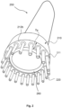
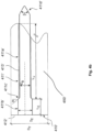
- Fig.1 shows a schematic representation of a wind turbine according to the invention.
- the wind turbine 100 has a tower 102 and a nacelle 104 on the tower 102.
- An aerodynamic rotor 106 with three rotor blades 108 and a spinner 110 is provided on the nacelle 104.
- the aerodynamic rotor 106 is set in rotation by the wind during operation of the wind turbine and thus also rotates an electrodynamic rotor or rotor of a generator which is directly or indirectly coupled to the aerodynamic rotor 106.
- the electrical generator is arranged in the nacelle 104 and generates electrical energy.
- the pitch angles of the rotor blades 108 can be changed by pitch motors on the rotor blade roots 109 of the respective rotor blades 108.
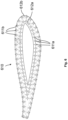
- Fig.2 shows a schematic representation of a rotor blade segment 250 with a connection interface 210 with several recesses 211, in each of which a tension element 220 is introduced.
- the outer peripheral surface of the respective recesses 211 is formed by the connection material.
- the openings of the recesses 211 are located in the end face 212b of the connection interface 210.
- the end face 212b of the The connection interface is applied to the outside of the connection end of the rotor blade segment 250.
- the connection end of the rotor blade segment 250 has an end face 260 which lies in a plane with the end face 212b of the connection interface 210.
- the diameter of the recesses 211 preferably corresponds to approximately one third, preferably approximately 10 to 50%, in particular approximately 20 to 40%, of the extent D F of the connection interface 210 orthogonal to a longitudinal axis of the recess 211 and/or the rotor blade segment 250.
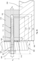
- Fig. 3a shows a schematic longitudinal section through a recess 311 in a connection interface 310 with an inserted tension element 320 with a diameter D and a total length which is made up of the length L B1 of the part received in the recess 311 and the length L B2 of the part protruding from the recess 311.
- the outer peripheral surface of the recess 311 is formed by the connection material.
- the recess 311 is designed as a blind hole, the opening is in the end face 312 of the connection interface 310.
- Adhesive 330 is introduced into the recess.
- the recess 311 is essentially cylindrical and has an essentially cylindrical shaft part 311a with a first diameter D B and an enlarged head part 311b adjacent to the opening with a second diameter D ⁇ , the second diameter D ⁇ being larger than the first diameter D B .
- the shaft part 311 is several times longer than the head part 311b with a length L E .
- the recess 311 has a base length L G and a total length L B . This longitudinal extension of the recess 311 along the longitudinal axis is longer than the length L B1 of the part of the tension element 320 to be accommodated therein and corresponds to a multiple of the diameter D B of the recess 311.
- the diameter D B of the recess 311 preferably corresponds to approximately one third, preferably approximately 10 to 50%, in particular approximately 20 to 40%, of the extension D F of the connection interface 310 orthogonal to a longitudinal axis of the recess 311 and/or to a longitudinal axis of the rotor blade component segment 350.
- connection interface 310 is applied to a connection end of a rotor blade component segment 350, which can be a rotor blade segment.
- the rotor blade component segment 350 has an end face 360, which can be arranged flush with the end face 312 of the connection interface 310.
- the end face 312 of the connection interface 310 is flattened in an area around the recesses using a milling cutter or a drill, so that the end face 312 has a flat surface.
- the end face 312 serves as Support surface for a spacer 340.
- the spacer 340 rests on one side on the front face 312 and on the opposite side on a steel adapter 380.
- the steel adapter 380 can already represent part of the test stand to which the rotor blade component segment 350 is connected via the connection interface 310.
- the steel adapter has a through hole for the tension element 320, in which the tension element 320 is arranged.
- the tension element 320 is screwed against the steel adapter 380 with a washer 381 and a nut 382, which is arranged on the thread of the tension element 320.
- all tension elements are screwed to the steel adapter 380 in this way.
- several spacers 340 can be used, which can have different thicknesses, wherein the thicknesses can be selected such that the end faces of the spacers 340, which are connected to the steel adapter 380, lie in a common plane.
- connection interface 310 can be applied inside or outside to the connection end of the rotor blade component segment 350. In the embodiment shown, the connection interface 310 can thus be applied on the inside or on the outside to the connection end of the rotor blade component segment 350.
- Embodiments with multi-row connections may also be preferred.
- Embodiments with a connection interface arranged on the inside and on the outside at the connection end of the rotor blade component segment may also be preferred.
- embodiments with a connection interface that is formed at least partially by the rotor blade component segment, preferably by spar caps of the rotor blade component segment may also be preferred.
- the tension element 320 received in the recess 311 has an external thread, wherein the internal thread of the recess 311 and the external thread of the tension element 320 are designed to engage with one another.
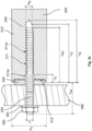
- Fig. 3b shows a schematic longitudinal section through a recess 311 in a connection interface 310 with an inserted tension element 320 with a diameter D and a total length which is made up of the length L B1 of the part accommodated in the recess 311 and the length L B2 of the part protruding from the recess 311. Partly composed.
- the outer peripheral surface of the recess 311 is formed by the connection material.
- the recess 311 is designed as a blind hole, the opening is in the end face 312 of the connection interface 310.
- Adhesive 330 is introduced into the recess.
- the recess 311 is essentially cylindrical and has an essentially cylindrical shaft part 311a with a first diameter D B and an enlarged head part 311b adjacent to the opening with a second diameter D ⁇ , the second diameter D ⁇ being larger than the first diameter D B .
- the shaft part 311a is many times longer than the head part 311b with a length L ⁇ .
- the recess 311 has a base length L G and a total length L B. This longitudinal extension of the recess 311 along the longitudinal axis is longer than the length L B1 of the part of the tension element 320 to be received therein and corresponds to a multiple of the diameter D B of the recess 311.
- the diameter D B of the recess 311 preferably corresponds to approximately one third, preferably approximately 10 to 50%, in particular approximately 20 to 40%, of the extension D F of the connection interface 310 orthogonal to a longitudinal axis of the recess 311 and/or to a longitudinal axis of the rotor blade component segment 350.
- connection interface 310 is applied to a connection end of a rotor blade component segment 350, which can be a rotor blade segment.
- the rotor blade component segment 350 has an end face 360, which can be arranged flush with the end face 312 of the connection interface 310.
- a filler 345 is applied to the front surface 312 of the connection interface 310. It is preferred if the filler 345 comprises epoxy resin or consists essentially of it.
- a steel adapter 380 is arranged on the filler 345.
- the steel adapter 380 can already represent part of the test stand to which the rotor blade component segment 350 is to be connected via the connection interface 310.
- the steel adapter 380 has a through hole for the tension element 320, in which the tension element 320 is arranged.
- the tension element 320 is screwed to the steel adapter 380 with a washer 381 and a nut 382, which is arranged on the thread of the tension element 320.
- the filler 345 can be used in particular to compensate for unevenness in the front surface 312.
- all tension elements are screwed to the steel adapter 380 in this way.
- the filler 345 can be applied around all tension elements.
- the Filler may have different thicknesses at different locations, and the thicknesses may be selected so that filler 345 forms a plane on the side where filler 345 is in contact with steel adapter 380.
- connection interface 310 can in particular be applied inside or outside to the connection end of the rotor blade component segment 350. In the embodiment shown, the connection interface 310 can thus be applied on the inside or on the outside to the connection end of the rotor blade component segment 350.
- Embodiments with multi-row connections may also be preferred.
- Embodiments with a connection interface arranged on the inside and on the outside at the connection end of the rotor blade component segment may also be preferred.
- embodiments with a connection interface that is formed at least partially by the rotor blade component segment, preferably by spar caps of the rotor blade component segment may also be preferred.
- the tension element 320 received in the recess 311 has an external thread, wherein the internal thread of the recess 311 and the external thread of the tension element 320 are designed to engage with one another.
- Fig. 3c shows a sectional view of a section of a connection interface 310' at a connection end, wherein as in Fig. 3a a steel adapter 380 is attached to the connection interface 310 ⁇ .
- the connection interface 310' is formed by a rotor blade component segment 350'.
- the recess 311' is arranged in a spar flange of the rotor blade component segment 350'.
- the tension element 320 is received in the recess 311' in the spar flange.
- the remaining structure is analogous to the structure of the rotor blade component segment 350'.
- Fig. 3d shows a sectional view of a section of a connection interface 310' at a connection end, wherein as in Fig. 3b a steel adapter 380 is attached to the connection interface 310 ⁇ .
- the Connection interface 310' is formed by a rotor blade component segment 350'.
- the recess 311' is arranged in a spar flange of the rotor blade component segment 350'.
- the tension element 320 is received in the recess 311' in the spar flange.
- the remaining structure is analogous to the structure of the Fig. 3b shown embodiment.
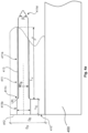
- Fig. 4a shows a schematic longitudinal section through a recess 411 in a connection interface 410.
- the outer peripheral surface of the recess 411 is formed by the connection material.
- the recess 411 is designed as a blind hole, the opening is in the end face 412 of the connection interface 410.
- the recess 411 is essentially cylindrical and has an essentially cylindrical shaft part 411a with a first diameter D B and an enlarged head part 411b adjacent to the opening with a second diameter D ⁇ , the second diameter D ⁇ being larger than the first diameter D B .
- a transition section 411c is formed, which preferably has an inclination angle a of 30 to 60°, in particular of 45°.
- an end section 411d is formed, which preferably has an inclination angle ⁇ of 60 to 120°.
- the shaft part 411a has an internal thread 413, which is cut directly into the connection material.
- the shaft part 411a with a length Lv is several times longer than the head part 411b with a length L ⁇ .
- the longitudinal extension of the recess 411 along the longitudinal axis corresponds to a multiple of the diameter D B of the recess 411.
- the diameter D B of the recess 411 preferably corresponds to approximately one third, preferably approximately 10 to 50%, in particular approximately 20 to 40%, of the extension D F of the connection interface 410 orthogonal to a longitudinal axis of the recess 411 and/or a longitudinal axis of the rotor blade.
- connection interface 410 is applied to a connection end of a rotor blade component segment 450, which can be a rotor blade segment.
- the rotor blade component segment 450 has an end face that is arranged flush with the end face 412 of the connection interface 410.
- the connection interface 410 can be applied in particular inside or outside to the connection end of the rotor blade component segment 450. In the embodiment shown, the connection interface 410 can thus be applied to the inside or the outside at the connection end of the rotor blade component segment 450.
- connection interfaces 210, 310, 410 preferably have a connection material that is identical to a rotor blade material. Furthermore, the connection interfaces 210, 310, 410 are preferably connected to the rotor blade component segment in a materially bonded manner.
- connection interfaces 210, 310, 410 the rotor blade component segment can be fixed to a test stand by means of connecting elements and/or tension elements for testing the rotor blade component segment.
- the diameter D ⁇ is approximately 1.25 times the diameter D B .
- the length L ⁇ is preferably approximately 1.5 times the diameter D B .
- the length Lv is approximately 6 times the diameter D B .
- Fig. 4b shows a schematic longitudinal section through a recess 411' in a connection interface 410 ⁇ .
- the connection interface 410' is formed by a rotor blade component segment 450'.
- the recess 411' is arranged in a spar flange of the rotor blade component segment 450'.
- the remaining structure is analogous to that shown in Fig. 4a shown embodiment.
- Fig. 5a shows a rotor blade segment 550 with a connection interface 510a applied to the connection end of the rotor blade segment 550.
- the connection interface 510a is arranged on the inside of the connection end of the rotor blade segment 550.
- the connection interface has an end face 512a which is aligned with the end face of the connection end of the rotor blade segment 550.
- Fig. 5b shows a rotor blade segment 550 with a connection interface 510b applied to the connection end of the rotor blade segment 550.
- the connection interface 510b is arranged on the outside of the connection end of the rotor blade segment 550.
- the connection interface has an end face 512b which is aligned with the end face of the connection end of the rotor blade segment 550.
- Fig. 5c shows a rotor blade segment 550 with a connection interface 510, 510b applied to the connection end of the rotor blade segment 550.
- the connection interface 510a, 510b is arranged on the inside and on the outside of the connection end of the rotor blade segment 550.
- the connection interface has an end face 512a, 512b which is aligned with the end face of the connection end of the rotor blade segment 550.
- connection interface 510a, 510b the rotor blade segment can be fixed to a test stand by means of connecting elements and/or tension elements for testing the rotor blade segment.
- Fig.6 shows a top view of a connection interface 610 of a rotor blade segment.
- the connection interface 610 is applied inside and outside to the connection end of the rotor blade segment.
- the connection interface 610 thus comprises a part applied on the inside with an end face 612a of the part applied on the inside and a part applied on the outside with an end face 612b of the part applied on the outside.
- the end face of the connection interface 612a, 612b is aligned with the end face of the connection end of the rotor blade segment.
- the recesses 611a, 611b on the connection interface 610 are formed in two rows.
- the connection interface 610 has inner recesses 611a and outer recesses 611b.
- the rotor blade segment can be connected to a test stand via this connection interface 610 by means of connecting elements and/or tension elements.
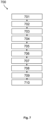
- Fig.7 shows a schematic representation of a method 700 for testing a rotor blade component of a rotor blade for a wind turbine.
- the method 700 comprises the following steps: In a step 701, producing the rotor blade component of a rotor blade for a wind turbine. In a step 702, dividing a rotor blade component of a rotor blade for a wind turbine into two, three or more rotor blade component segments. In a step 703, applying the connection interface to a connection end of one of the rotor blade component segments.
- a step 704 introducing recesses into the connection interface at the connection end and preferably producing flat sections on the front face of the connection interface in the region of the openings of the recesses, preferably by means of drilling and/or face milling, and preferably arranging spacers on the front face in the region of the recesses. It is preferred if the spacers have individually adapted thicknesses so that the spacers have unevenness can compensate.
- a step 705 arranging connecting elements and/or tension elements in some or all of the recesses and preferably applying a filler to the face of the connection interface.
- the filler may comprise or consist essentially of epoxy resin.
- a step 706 transporting the rotor blade component segment to a test stand.
- a step 707 connecting the rotor blade component segment to a test stand.
- a step 708 testing the rotor blade component segment on a test stand.
- a step 709 dismantling the rotor blade component segment from a test stand.
- a step 710 disposing of the rotor blade component segment.
- Fig.8 shows a schematic representation of a method 700 for testing a rotor blade component of a rotor blade for a wind turbine.
- the method described further comprises additional steps: in a step 711, transporting a further rotor blade component segment or all further rotor blade component segments of the same rotor blade component to a test stand. in a step 712, connecting a further rotor blade component segment or all further rotor blade component segments of the same rotor blade component to a test stand. in a step 713, testing a further rotor blade component segment or all further rotor blade component segments of the same rotor blade component on a test stand.
- a step 714 dismantling a further rotor blade component segment or all further rotor blade component segments of the same rotor blade component from a test stand. in a step 715, disposing of a further rotor blade component segment or all further rotor blade component segments of the same rotor blade component.
Landscapes
- Engineering & Computer Science (AREA)
- Physics & Mathematics (AREA)
- General Physics & Mathematics (AREA)
- Aviation & Aerospace Engineering (AREA)
- Life Sciences & Earth Sciences (AREA)
- Sustainable Development (AREA)
- Sustainable Energy (AREA)
- Chemical & Material Sciences (AREA)
- Combustion & Propulsion (AREA)
- Mechanical Engineering (AREA)
- General Engineering & Computer Science (AREA)
- Wind Motors (AREA)
Description
- Die Erfindung betrifft ein Verfahren zum Testen einer Rotorblattkomponente eines Rotorblatts für eine Windenergieanlage und ein Rotorblattkomponentensegment eines Rotorblatts für eine Windenergieanlage.
- Im Entwicklungsprozess, insbesondere im Rahmen von Zertifizierungsverfahren, von Rotorblättern für Windenergieanlagen werden Rotorblätter typischerweise sowohl statischen als auch dynamischen Tests unterzogen. Bei solchen Tests wird ein Rotorblatt in einem Teststand angeordnet und an der Blattwurzel des Rotorblatts fixiert. Bei der Durchführung von dynamischen Tests werden dann üblicherweise an einer Position oder an mehreren Positionen entlang des Rotorblatts zyklische Kräfte aufgebracht. So kann das Rotorblatt beispielsweise zu einer Eigenfrequenzschwingung angeregt werden, indem die zyklische Kraftaufbringung mit einer Frequenz, die einer der Eigenfrequenzen des Rotorblatts entspricht, erfolgt. Zum Testen des Ermüdungsverhaltens eines Rotorblatts in einem Ermüdungstest erfolgt typischerweise eine solche zyklische Kraftaufbringung, bei der das Rotorblatt mit einer Eigenfrequenz des Rotorblatts angeregt wird, um dieses in eine Eigenfrequenzschwingung zu versetzen.
- Um die Leistungsfähigkeit und die Kosten von Windenergieanlagen zu verbessern, ist der Trend zu erkennen, dass die Anlagen zunehmend größere Bauformen und/oder höhere Nennleistungen aufweisen. Die größere Bauform bezieht sich insbesondere auf den
- Rotordurchmesser und auf die Nabenhöhe der Windenergieanlagen. Rotorblätter moderner Windenergieanlagen können Längen von über 100 Metern aufweisen.
- Das Testen, und insbesondere das zyklische Testen, von Rotorblättern ist insgesamt mit einem hohen Zeit- und Kostenaufwand verbunden. Dies gilt insbesondere für sehr lange Rotorblätter. Ein weiteres Problem, das beim Testen von Rotorblättern auftritt, besteht darin, dass abschnittsweise Belastungen am Rotorblatt deutlich oberhalb der für diese Abschnitte geforderten Belastungen auftreten können. Dies kann zu Schädigungen des Rotorblatts führen, wodurch zeit- und kostenaufwändige Reparaturarbeiten und damit verbundene Unterbrechungen des Tests auftreten können.
- Das Deutsche Patent- und Markenamt hat in der Prioritätsanmeldung zu vorliegender Anmeldung folgenden Stand der Technik recherchiert:
EP 3 418 560 A1 . -
US 2010/122442 A1 offenbart ein Verfahren, umfassend Zusammenfügen einer integralen Trennwand und einer Turbinenblattschale, um ein Turbinenblatt zu bilden; und Trennen des Blatts in zwei Blattsegmente an einer Stelle, die die integrale Trennwand aufweist, sodass jedes Blattsegment einen Abschnitt der integralen Trennwand und einen Abschnitt der Blattschale umfasst.EP 3 418 560 A1 offenbart einen Prüfstand für ein Längsstrukturelement, wie ein Blattsegment, eine Zwischenblattverbindung oder eine andere Art von Struktur einer Windturbine, auf die eine Reihe von mehrachsigen Biege-, Torsions-, Scher- und Axialbelastungen aufgebracht wird. - Es ist daher die Aufgabe der vorliegenden Erfindung, eine verbesserte Lösung bereitzustellen, welche wenigstens eines der genannten Probleme adressiert. Insbesondere ist es Aufgabe der Erfindung, eine Lösung bereitzustellen, die den Zeit- und Kostenaufwand bei dem dynamischen Testen von Rotorblättern für Windenergieanlagen verringert.
- Gemäß einem ersten Aspekt wird die eingangs genannte Aufgabe gelöst durch ein Verfahren zum Testen einer Rotorblattkomponente eines Rotorblatts für eine Windenergieanlage nach Anspruch 1.
- Vorzugsweise erfolgt das Teilen der Rotorblattkomponente eines Rotorblatts für eine Windenergieanlage in zwei, drei oder mehrere Rotorblattkomponentensegmente vor dem Einbringen von Ausnehmungen in die Anschlussschnittstelle.
- Ein Rotorblatt erstreckt sich in der Regel mit seiner Haupterstreckungsrichtung entlang einer Längsachse von einer Rotorblattwurzel zu einer Rotorblattspitze. Das Teilen der Rotorblattkomponente, beispielsweise des Rotorblatts, erfolgt vorzugsweise mittels Sägen mit einer Seilsäge oder mittels einer Kreissäge. Das Teilen der Rotorblattkomponente erfolgt vorzugsweise entlang einer Ebene, die orthogonal zur Längsachse des Rotorblatts und/oder des Rotorblattkomponentensegments und/oder des Rotorblattsegments und/oder der Rotorblattwurzel angeordnet ist.
- Die Anschlussschnittstelle liegt vorzugsweise in einer Ebene, zu der die Längsachse des Rotorblatts und/oder des Rotorblattkomponentensegments und/oder des Rotorblattsegments im Wesentlichen orthogonal orientiert ist. Die Anschlussschnittstelle ist vorzugsweise an dem Anschlussende eines der Rotorblattkomponentensegmente angeordnet.
- Die Anschlussschnittstelle kann teilweise oder vollständig durch eines der Rotorblattkomponentensegmente, insbesondere durch einen Teil eines der Rotorblattkomponentensegmente, gebildet werden. Insbesondere kann die Anschlussschnittstelle eine Endebene eines der Rotorblattkomponentensegmente, insbesondere eines Rotorblattsegments, sein. Die Anschlussschnittstelle kann, insbesondere teilweise oder vollständig, durch eine Trennfläche eines der Rotorblattkomponentensegmente, entlang der das Teilen der Rotorblattkomponente erfolgt ist, gebildet werden. Die Anschlussschnittstelle kann, insbesondere teilweise oder vollständig, durch eine Endebene im Bereich von Holmgurten eines der Rotorblattkomponentensegmente gebildet werden.
- Die Anschlussschnittstelle kann auch, insbesondere teilweise oder vollständig, an ein Anschlussende eines der Rotorblattkomponentensegmente aufgebracht werden, wobei das Aufbringen der Anschlussschnittstelle vorzugsweise derart erfolgt, dass die Anschlussschnittstelle quer zur Längsachse des Rotorblatts und/oder des Rotorblattkomponentensegments und/oder des Rotorblattsegments innerhalb und/oder außerhalb des Anschlussendes angeordnet ist.
- Die Ausnehmungen sind vorzugsweise jeweils im Wesentlichen zylinderförmig ausgebildet. Ferner vorzugsweise weisen die Ausnehmungen jeweils einen im Wesentlichen zylinderförmigen Schaftteil mit einem ersten Durchmesser auf und einen an die Öffnung angrenzenden erweiterten Kopfteil auf mit einem zweiten Durchmesser auf, wobei der zweite Durchmesser größer ist als der erste Durchmesser. In Längsrichtung der Ausnehmungen ist jeweils der Schaftteil vorzugsweise länger als der Kopfteil, insbesondere um ein Vielfaches länger als der Kopfteil. Vorzugsweise ist eine Längsachse jeder der Ausnehmungen im Wesentlichen parallel zu einer Längsachse des Rotorblatts.
- Eine weitere bevorzugte Fortbildung zeichnet sich dadurch aus, dass die Anschlussschnittstelle eine Vielzahl von Ausnehmungen, vorzugsweise mindestens 20 oder mindestens 30 oder mindestens 40 Ausnehmungen, aufweist. Die Vielzahl von Ausnehmungen kann einreihig oder mehrreihig, insbesondere zweireihig, angeordnet sein. Dabei ist insbesondere bevorzugt, dass die Ausnehmungen auf einer Umfangslinie eines Polygons liegen oder auf zwei, drei oder mehreren im wesentlichen konzentrischen Polygonen liegen. Vorzugsweise weist das Polygon die Querschnittsform und/oder die Form der Außenkontur des Rotorblattkomponentensegments am Anschlussende auf. Die Ausnehmungen können auch auf einer ellipsenförmigen Bahn oder auf mehreren ellipsenförmigen Bahnen liegen. Es ist ferner bevorzugt, dass die Ausnehmungen in Umfangsrichtung im Wesentlichen äquidistant angeordnet sind.
- Ein erster Vorteil eines solchen Verfahrens besteht darin, dass die benötigte Zeit zum Testen eines Rotorblatts deutlich reduziert werden kann, wenn nicht das ungeteilte Rotorblatt getestet wird, sondern mehrere Rotorblattkomponentensegmente, insbesondere Rotorblattsegmente, separat voneinander getestet werden. Die Rotorblattsegmente weisen im Vergleich zum ungeteilten Rotorblatt in der Regel veränderte Eigenfrequenzen auf, sodass die Rotorblattsegmente zu Schwingungen mit höheren Frequenzen angeregt werden können. Dadurch kann in Ermüdungstests eine bestimmte Zyklenanzahl innerhalb einer kürzeren Zeit erreicht werden, wodurch die Gesamtzeit der Tests reduziert werden kann. Die benötigte Zeit zum Testen kann durch das beschriebene Verfahren um mehrere Monate reduziert werden.
- Ein weiterer Vorteil besteht darin, dass durch die Verwendung einer Anschlussschnittstelle am Anschlussende eines der Rotorblattkomponentensegmente und durch das Einbringen von Ausnehmungen in die Anschlussschnittstelle ein kostengünstiger, relativ schnell herstellbarer und zuverlässiger Anschluss zur Fixierung an einem Teststand bereitgestellt werden kann.
- Ein weiterer Vorteil besteht darin, dass abschnittsweise Überlasten, die oberhalb der für diese Abschnitte geforderten Belastungen liegen, beim Testen von Rotorblattkomponentensegmenten im Vergleich zum Testen von ganzen Rotorblättern deutlich reduziert werden können. Somit können durch die Überlasten bedingte Schädigungen während des Tests reduziert und/oder vermieden werden, wodurch Unterbrechungen der Tests sowie aufwändige Reparaturarbeiten am Rotorblatt reduziert und/oder vermieden werden können. So kann beispielsweise bei einem herkömmlichen Rotorblatttest am ganzen Blatt aufgrund der methodisch bedingten Überlasten an bestimmten Stellen eine 10-fach höhere Belastung im Vergleich zur geforderten Belastung auftreten, während beim Testen von Rotorblattkomponentensegmenten, insbesondere Rotorblattsegmenten, beispielsweise lediglich eine 3,5-fach höhere Belastung im Vergleich zu der geforderten Belastung auftritt.
- Ein weiterer Vorteil besteht darin, dass im Fall einer Unterbrechung eines Tests von einem der Rotorblattkomponentensegmente zeitlich parallel stattfindende Tests von weiteren Rotorblattkomponentensegmenten nicht unterbrochen werden müssen. Dies wirkt sich ebenfalls positiv auf die insgesamt zum Testen benötigte Zeit aus.
- Gemäß einer bevorzugten Ausführungsform ist vorgesehen, dass die Rotorblattkomponente ein Rotorblatt oder eine Hinterkante eines Rotorblatts oder eine Endkante eines Rotorblatts ist.
- Vorzugsweise ist die Rotorblattkomponente ein ganzes Rotorblatt. Ein Rotorblattkomponentensegment kann ein Rotorblattsegment sein. Ein Rotorblattsegment ist insbesondere ein Abschnitt eines Rotorblatts. Ein Rotorblatt kann beispielsweise in zwei oder drei Rotorblattsegmente und gegebenenfalls weitere Rotorblattkomponentensegmente geteilt werden. In einer bevorzugten Ausführungsform kann die Anschlussschnittstelle auf das Anschlussende des Rotorblattkomponentensegments, das ein Segment des Rotorblatts sein kann, aufgebracht werden.
- Die Rotorblattkomponente kann auch eine Hinterkante eines Rotorblatts sein. Die Hinterkante eines Rotorblatts ist bei bestimmungsgemäßer Bewegung des Rotorblattes im Wesentlichen in entgegengesetzten Richtung zur Bewegungs-, also Drehrichtung, des Rotorblattes und damit des aerodynamischen Rotors der Windenergieanlage gerichtet. In einer bevorzugten Ausführungsform kann die Anschlussschnittstelle auf das Anschlussende des Rotorblattkomponentensegments, das ein Teil der Hinterkante sein kann, aufgebracht werden.
- Die Rotorblattkomponente kann auch eine Endkante eines Rotorblatts sein. Vorzugsweise ist die Endkante an dem Rotorblatt in einem Bereich der Hinterkante, beispielsweise von einem mittleren Bereich des Rotorblatts bis zur Rotorblattspitze, angeordnet. Eine solche Endkante kann als dreidimensionales glasfaserverstärktes Element ausgebildet sein und/oder Rotorblattmaterial umfassen oder daraus bestehen. In einer bevorzugten Ausführungsform kann die Anschlussschnittstelle auf das Anschlussende des Rotorblattkomponentensegments, das ein Teil der Endkante sein kann, aufgebracht werden.
- Ferner umfasst das Verfahren Testen des Rotorblattkomponentensegments an einem Teststand.
- Es ist ferner bevorzugt, dass das Verfahren umfasst: Aufbringen der Anschlussschnittstelle an das Anschlussende, und/oder Herstellen der Rotorblattkomponente eines Rotorblatts für eine Windenergieanlage, und/oder Anordnen von Verbindungselementen und/oder Zugelementen in einigen oder allen Ausnehmungen, und/oder Transportieren des Rotorblattkomponentensegments zu einem Teststand, und/oder Anschließen des Rotorblattkomponentensegments an einen Teststand, und/oder Demontieren des Rotorblattkomponentensegments von einem Teststand, und/oder Entsorgen des Rotorblattkomponentensegments.
- Es ist bevorzugt, wenn nach dem Aufbringen der Anschlussschnittstelle an dem Anschlussende eines der Rotorblattkomponentensegmente ein Teil der Anschlussschnittstelle und ein Teil des Anschlussendes, vorzugsweise mittels Sägen mit einer Seilsäge oder mittels einer Kreissäge, abgetrennt wird, sodass die Anschlussschnittstelle und das Anschlussende Kanten aufweisen, die in einer Ebene, die im Wesentlichen quer zu einer Rotorblattlängsachse angeordnet ist, angeordnet sind. Vorzugsweise werden die Kante der Anschlussschnittstelle und die Kante des Anschlussendes durch einen gemeinsamen Sägeschnitt gebildet. Vorzugsweise ist die Anschlussschnittstelle nach dem Aufbringen der Anschlussschnittstelle an das Anschlussende stoffschlüssig mit dem Rotorblattkomponentensegment verbunden.
- Mit einer Anschlussschnittstelle, die auf einem der Rotorblattkomponentensegmente aufgebracht wird und wie beschrieben ausgebildet ist, ist es auf vorteilhafte Weise möglich Rotorblattkomponentensegmente an einen Teststand anzubinden. Eine solche Anschlussschnittstelle kann unabhängig von der Form und/oder Kontur des Rotorblattkomponentensegments und der Form und/oder Kontur des Rotorblattkomponentensegments auf das Rotorblattkomponentensegment aufgebracht werden. Eine solche Anschlussschnittstelle kann unabhängig von der Form und/oder Kontur des Anschlussendes des Rotorblattkomponentensegments und der Form und/oder Kontur des Anschlussendes des Rotorblattkomponentensegments auf das Rotorblattkomponentensegment aufgebracht werden.
- Vorzugsweise umfasst das Herstellen der Rotorblattkomponente eines Rotorblatts für eine Windenergieanlage das Herstellen eines Rotorblatts. Das Herstellen der Rotorblattkomponente eines Rotorblatts kann auch das Herstellen einer Hinterkante und/oder Endkante umfassen.
- Vorzugsweise kann in jede der Ausnehmungen ein Verbindungselement und/oder ein Zugelement aufgenommen werden. Das in einer der Ausnehmungen aufgenommene Zugelement weist vorzugsweise ein Außengewinde auf, wobei das Innengewinde der Ausnehmung und das Außengewinde des Zugelements vorzugsweise für einen Eingriff miteinander ausgebildet sind. Es ist bevorzugt, wenn das Zugelement Stahl umfasst oder daraus besteht. Vorzugsweise wird das in einer der Ausnehmungen aufgenommene Zugelement mit seinem aus der Ausnehmung herausragenden Ende in einem Teststand angeschlossen werden zur Befestigung des Rotorblattkomponentensegments an dem Teststand.
- Es ist bevorzugt, wenn zwischen dem Rotorblattkomponentensegment und dem Teststand, an den das Rotorblattkomponentensegment angeschlossen wird, Ausgleichsscheiben angeordnet sind. Die Ausgleichsscheiben können Unebenheiten an der Stirnseite des Rotorblattkomponentensegments ausgleichen, sodass eine zuverlässige Verbindung zwischen dem Teststand und dem Rotorblattkomponentensegment hergestellt werden kann. Es können eine oder mehrere Ausgleichsscheiben verwendet werden. Vorzugsweise werden Ausgleichsscheiben mit unterschiedlichen Dicken verwendet, sodass alle Unebenheiten ausgeglichen werden.
- Vorzugsweise ist eine der Anzahl von Ausnehmungen entsprechende Anzahl an Zugelementen vorgesehen, wobei vorzugsweise in jeder Ausnehmung ein Zugelement angeordnet ist oder angeordnet werden kann. In einer weiteren bevorzugten Ausführungsform ist vorgesehen, dass die Zugelemente in den Ausnehmungen verklebt sind. Insbesondere ist bevorzugt, dass die Zugelemente in den Ausnehmungen verschraubt und verklebt sind. Hierzu wird vor dem Einbringen der Zugelemente in die Ausnehmungen ein Klebstoff in die Ausnehmungen eingebracht. Als Klebstoff kommen vorzugsweise dünnflüssige Klebstoffe und/oder Klebstoffe auf Epoxid- und/oder Polyurethan- und/oder Methylacrylatbasis zum Einsatz.
- In einer weiteren bevorzugten Ausführungsform ist vorgesehen, dass das Rotorblattkomponentensegment und/oder das Anschlussmaterial eine Steifigkeit aufweist, die geringer ist, insbesondere um ein Vielfaches geringer ist, vorzugsweise um mindestens das Fünffache geringer ist, beispielsweise um mindestens das Siebenfache geringer ist, als die Steifigkeit eines Materials des Zugelements, wobei als Maß der Steifigkeit insbesondere der Elastizitätsmodul und/oder der Schubmodul des jeweiligen Materials dient.
- Es ist bevorzugt, wenn die Verfahrensschritte in der folgenden Reihenfolge erfolgen: Herstellen der Rotorblattkomponente eines Rotorblatts für eine Windenergieanlage, Aufbringen der Anschlussschnittstelle an das Anschlussende, Anordnen von Verbindungselementen und/oder Zugelementen in einigen oder allen Ausnehmungen, Transportieren des Rotorblattkomponentensegments zu einem Teststand, Anschließen des Rotorblattkomponentensegments an einen Teststand, Testen des Rotorblattkomponentensegments an einem Teststand, Demontieren des Rotorblattkomponentensegments von dem Teststand.
- In einer bevorzugten Ausführungsform ist vorgesehen, dass einige oder alle Ausnehmungen gleich ausgebildet sind, und/oder einige oder alle Ausnehmungen ausgebildet sind zur Aufnahme von Verbindungselementen und/oder Zugelementen zum Anschließen des Rotorblattkomponentensegments an einen Teststand, und/oder eine jeweilige Umfangsfläche einiger oder aller Ausnehmungen von einem Anschlussmaterial gebildet ist, und/oder einige oder alle Ausnehmungen als Sacklöcher ausgebildet sind, und/oder einige oder alle Ausnehmungen als Durchgangslöcher ausgebildet sind, und/oder eine jeweilige Umfangsfläche einiger oder aller Ausnehmungen ein Innengewinde aufweist, und/oder einige oder alle Ausnehmungen als Bohrungen ausgebildet sind, und/oder einige oder alle Ausnehmungen äquidistant voneinander beabstandet sind.
- Es ist bevorzugt, wenn die Ausnehmungen den gleichen Durchmesser und die gleiche Länge aufweisen. Ferner ist es bevorzugt, dass die Verbindungselemente und/oder Zugelemente mit den Ausnehmungen formschlüssig und/oder stoffschlüssig verbunden sind und mit dem Teststand formschlüssig und/oder stoffschlüssig verbunden sind. Vorzugsweise sind die Ausnehmungen als Sacklöcher ausgebildet, wobei die Öffnung in der Stirnfläche der Anschlussschnittstelle liegt. Ein Vorteil liegt darin, dass keine Hülsen in den Ausnehmungen zur Kraftübertragung zwischen den Verbindungselementen und der Anschlussschnittstelle vorhanden sein müssen.
- In einer bevorzugten Ausführungsform ist vorgesehen, dass die Anschlussschnittstelle ein Anschlussmaterial umfasst oder daraus besteht, und/oder das Aufbringen einer Anschlussschnittstelle ein Auflaminieren von Anschlussmaterial ist oder umfasst, und/oder ein erstes Ende der Anschlussschnittstelle mit dem Anschlussende des Rotorblattkomponentensegments fluchtet, und/oder ein zweites Ende der Anschlussschnittstelle beabstandet ist von einem dem Anschlussende des Rotorblattkomponentensegments gegenüberliegenden Ende des Rotorblattkomponentensegments, und/oder das erste und das zweite Ende der Anschlussschnittstelle parallel zueinander sind.
- Es ist bevorzugt, dass die Rotorblattkomponentensegmente ein Rotorblattmaterial aufweisen oder im Wesentlichen aus einem Rotorblattmaterial bestehen. Es ist ferner bevorzugt, dass die Anschlussschnittstelle ein Anschlussmaterial aufweist oder im Wesentlichen aus einem Anschlussmaterial besteht. In einer bevorzugten Ausführungsform ist vorgesehen, dass das Rotorblattmaterial und das Anschlussmaterial identisch sind. Das Anschlussmaterial dient vorzugsweise als Aufdickung und/oder Verstärkung am Anschlussende. Die Anschlussschnittstelle und/oder andere Teile der Rotorblattkomponentensegmente können vorzugsweise ganz oder überwiegend aus Anschlussmaterial und/oder Rotorblattmaterial bestehen.
- Unter einem Auflaminieren von Anschlussmaterial ist insbesondere ein Aufbringen von Anschlussmaterial mittels Laminieren zu verstehen, wobei vorzugsweise mehrere Lagen aus Faser-Kunststoff-Verbundmaterial aufgebracht werden.
- Eine bevorzugte Weiterbildung zeichnet sich dadurch aus, dass das Anschlussmaterial ein faserverstärktes Verbundmaterial, insbesondere ein Faser-Kunststoff-Verbundmaterial, vorzugsweise ein glasfaserverstärktes Epoxidharz-Verbundmaterial, ist oder ein solches umfasst, und/oder das Anschlussmaterial mit einem Material der Rotorblattkomponente identisch und/oder gegenüber einem Material der Rotorblattkomponente verstärkt ist, und/oder die Anschlussschnittstelle auf einer Innenseite und/oder einer Außenseite des Anschlussendes des Rotorblattkomponentensegments angeordnet ist, und/oder sich die Anschlussschnittstelle über einen Großteil oder den gesamten Innenumfang und/oder Außenumfang des Anschlussendes des Rotorblattkomponentensegments erstreckt.
- Als Fasermaterialien des faserverstärkten Verbundmaterials können vorzugsweise organische Fasern und/oder anorganische Fasern und/oder Naturfasern zum Einsatz kommen. Anorganische Fasern sind beispielsweise Glasfasern, Basaltfasern, Borfasern, Keramikfasern oder Stahlfasern. Organische Fasern sind beispielsweise Aramidfasern, Kohlenstofffasern, Polyesterfasern und Polyethylenfasern (insbesondere High Performance Polyethylene (HPPE) Fasern, wie beispielsweise Dyneema-Fasern). Naturfasern sind beispielsweise Hanffasern, Flachsfasern oder Sisalfasern.
- Es ist bevorzugt, dass das Matrixmaterial des faserverstärkten Verbundmaterials einen Kunststoff umfasst oder besteht daraus. Der Kunststoff umfasst vorzugsweise ein Thermoplast und/oder ein Duroplast oder besteht daraus. Besonders bevorzugt sind beispielsweise duroplastische Kunststoffe, wie Polyesterharz (UP) und/oder Epoxidharz, und/oder thermoplatische Kunststoffe, wie Polyamid. Das Matrixmaterial des faserverstärkten Verbundmaterials kann auch Zement und/oder Beton und/oder Metall und/oder Keramik und/oder Kohlenstoff umfassen oder daraus bestehen.
- Eine weitere bevorzugte Weiterbildung ist gekennzeichnet durch Transportieren eines weiteren Rotorblattkomponentensegments oder aller weiteren Rotorblattkomponentensegmente derselben Rotorblattkomponente zu einem Teststand, und/oder Anschließen eines weiteren Rotorblattkomponentensegments oder allerweiteren Rotorblattkomponentensegmente derselben Rotorblattkomponente an einen Teststand, und/oder Testen eines weiteren Rotorblattkomponentensegments oder aller weiteren Rotorblattkomponentensegmente derselben Rotorblattkomponente an einem Teststand, und/oder Demontieren eines weiteren Rotorblattkomponentensegments oder allerweiteren Rotorblattkomponentensegmente derselben Rotorblattkomponente von einem Teststand.
- Es ist bevorzugt, wenn mehrere Rotorblattkomponentensegmente derselben Rotorblattkomponente zur gleichen Zeit an einem Teststand angeschlossen sind und/oder getestet werden. Dadurch kann das Testen der Rotorblattkomponente in vorteilhafter Weise in relativ kurzer Zeit durchgeführt werden.
- Ferner ist vorgesehen, dass an der Stirnfläche der Anschlussschnittstelle im Bereich der Öffnungen der Ausnehmungen ebene Flächen, vorzugsweise mittels Bohren und/oder Planfräsen, hergestellt werden. Die ebenen Flächen liegen auf zwei oder mehreren verschiedenen Ebenen. Dies hat den Vorteil, dass beim Herstellen der ebenen Flächen nicht darauf geachtet werden muss, dass diese in einer gemeinsamen Ebene. Vielmehr kann im Bereich jeder der Öffnungen der Ausnehmungen eine ebene Fläche erzeugt werden, die in einer Ebene liegt, die verschieden, aber vorzugsweise parallel, ist zu einer oder mehreren ebenen Flächen im Bereich von einer oder mehreren anderen Öffnungen der Ausnehmungen. Durch die Anordnung von Distanzstücken und/oder Spachtelmasse mit unterschiedlichen Dicken kann dann sichergestellt werden, dass die zur Anordnung an einem Teststand vorgesehenen Seiten der Distanzstücke und/oder Spachtelmasse im Wesentlichen in einer gemeinsamen Ebene liegen, so dass beispielsweise ein Stahladapter gut angeschlossen werden kann. Es werden die Abstände der ebenen Flächen von einer gemeinsamen Bezugsebene ermittelt und die Dicken der Distanzstücke und/oder Spachtelmasse auf diese gemessenen Abstände angepasst.
- Ferner ist vorgesehen, dass Distanzstücke auf die Stirnfläche der Anschlussschnittstelle im Bereich der Öffnungen der Ausnehmungen, insbesondere an den hergestellten ebenen Flächen, angeordnet werden, und/oder dass auf die Stirnfläche der Anschlussschnittstelle im Bereich der Öffnungen der Ausnehmungen, insbesondere an den hergestellten ebenen Flächen, eine Spachtelmasse aufgebracht wird und/oder angeordnet ist. Vorzugsweise weisen die Distanzstücke voneinander abweichende Dicken auf. Mit einer solchen Spachtelmasse können Unebenheiten auf vorteilhafte Weise ausgeglichen und/oder vermieden werden.
- Vorzugsweise werden die Verbindungselemente und/oder Zugelemente in Bohrungen, vorzugsweise Durchgangsbohrungen, eines Stahladapters angeordnet. Vorzugsweise werden die Verbindungselemente und/oder Zugelemente mit einer Verschraubung, insbesondere mittels einer Mutter, die auf dem Verbindungselement und/oder Zugelement angeordnet ist, gegen den Stahladapter verschraubt und/oder verspannt.
- Eine weitere bevorzugte Weiterbildung ist gekennzeichnet durch Entsorgen eines weiteren Rotorblattkomponentensegments oder aller weiteren Rotorblattkomponentensegmente derselben Rotorblattkomponente.
- Das Entsorgen kann ein Zerkleinern der Rotorblattkomponentensegmente umfassen.
- In einer bevorzugten Ausführungsform ist vorgesehen, dass die Anschlussschnittstelle eine Dicke aufweist, die mindestens dem 1,5-fachen eines Durchmessers einiger oder aller Ausnehmungen entspricht, insbesondere mindestens dem 2-fachen, mindestens dem 2,5-fachen oder mindestens dem 3-fachen eines Durchmessers einiger oder aller Ausnehmungen, und/oder die Anschlussschnittstelle eine Dicke aufweist von mindestens 2 cm, vorzugsweise von mindestens 3 cm, von mindestens 4 cm, von mindestens 5 cm, von mindestens 6 cm, von mindestens 7 cm, von mindestens 8 cm, von mindestens 9 cm, von mindestens 10 cm, von mindestens 11 cm, von mindestens 12 cm, oder von mindestens 15 cm, und/oder die Anschlussschnittstelle eine Tiefe aufweist, die mindestens dem 2-fachen eines Durchmessers einiger oder aller Ausnehmungen entspricht, insbesondere mindestens dem 3-fachen, mindestens dem 6-fachen oder mindestens dem 12-fachen eines Durchmessers einiger oder aller Ausnehmungen, und/oder die Anschlussschnittstelle eine Tiefe aufweist von mindestens 10 cm, vorzugsweise von mindestens 15 cm, von mindestens 20 cm, von mindestens 25 cm, von mindestens 30 cm, von mindestens 35 cm, von mindestens 40 cm, von mindestens 45 cm, oder von mindestens 50 cm.
- Unter der Dicke der Anschlussschnittstelle ist die Ausdehnung der Anschlussschnittstelle in Dickenrichtung zu verstehen, wobei die Dickenrichtung vorzugsweise orthogonal zur Längsachse des Rotorblattkomponentensegments und/oder der Längsachse des Rotorblattsegments und/oder der Rotorblattlängsachse orientiert ist. Unter der Tiefe der Anschlussschnittstelle ist die Ausdehnung der Anschlussschnittstelle in Längsrichtung zu verstehen, wobei die Längsrichtung vorzugsweise parallel zur Längsachse des Rotorblattkomponentensegments und/oder der Längsachse des Rotorblattsegments und/oder der Rotorblattlängsachse orientiert ist.
- Gemäß einem weiteren Aspekt der Erfindung wird die eingangs genannte Aufgabe gelöst durch ein Rotorblattkomponentensegment eines Rotorblatts für eine Windenergieanlage gemäß Anspruch 13.
- Der zuvor beschriebene weitere Aspekt und dessen mögliche Fortbildungen weisen Merkmale und Verfahrensschritte auf, die ihn besonders dafür geeignet machen, in einem hier beschriebenen Verfahren und seinen Fortbildungen verwendet zu werden.
- Zu den Vorteilen, Ausführungsvarianten und Ausführungsdetails der verschiedenen Aspekte der hier beschriebenen Lösungen und ihrer jeweiligen möglichen Fortbildungen wird auch auf die Beschreibung zu den entsprechenden Merkmalen, Details und Vorteilen der jeweils anderen Aspekte und ihrer Fortbildungen verwiesen.
- Bevorzugte Ausführungsbeispiele werden beispielhaft anhand der beiliegenden Figuren beschrieben. Es zeigen:
- Figur 1:
- eine schematische Darstellung einer Windenergieanlage;
- Figur 2:
- eine schematische Darstellung eines Rotorblattkomponentensegments in Form eines Rotorblattsegments mit einer Anschlussschnittstelle;
- Figur 3a:
- eine Schnittdarstellung eines Ausschnitts einer Anschlussschnittstelle an einem Anschlussende, wobei Ausgleichsscheiben an der Anschlussschnittstelle angebracht sind;
- Figur 3b:
- eine Schnittdarstellung eines Ausschnitts einer Anschlussschnittstelle an einem Anschlussende, wobei eine Ausgleichsschicht an der Anschlussschnittstelle aufgebracht ist;
- Figur 3c:
- eine Schnittdarstellung eines Ausschnitts einer Anschlussschnittstelle an einem Anschlussende, wobei Ausgleichsscheiben an der Anschlussschnittstelle angebracht sind und die Anschlussschnittstelle durch ein Rotorblattkomponentensegment gebildet wird;
- Figur 3d:
- eine Schnittdarstellung eines Ausschnitts einer Anschlussschnittstelle an einem Anschlussende, wobei eine Ausgleichsschicht an der Anschlussschnittstelle aufgebracht ist und die Anschlussschnittstelle durch ein Rotorblattkomponentensegment gebildet wird;
- Figur 4a:
- eine Schnittdarstellung eines Ausschnitts einer Anschlussschnittstelle an einem Anschlussende;
- Figur 4b:
- eine Schnittdarstellung eines Ausschnitts einer Anschlussschnittstelle an einem Anschlussende, wobei die Anschlussschnittstelle durch ein Rotorblattkomponentensegment gebildet wird;
- Figur 5a:
- eine schematische Darstellung eines Rotorblattkomponentensegments in Form eines Rotorblattsegments mit einer auf der Innenseite des Rotorblattkomponentensegments aufgebrachten Anschlussschnittstelle;
- Figur 5b:
- eine schematische Darstellung eines Rotorblattkomponentensegments in Form eines Rotorblattsegments mit einer auf der Außenseite des Rotorblattkomponentensegments aufgebrachten Anschlussschnittstelle;
- Figur 5c:
- eine schematische Darstellung eines Rotorblattkomponentensegments in Form eines Rotorblattsegments mit einer auf der Innenseite und auf der Außenseite des Rotorblattkomponentensegments aufgebrachten Anschlussschnittstelle;
- Figur 6:
- eine schematische Darstellung einer Draufsicht auf die Kante eines Rotorblattkomponentensegments mit einer auf der Innenseite und auf der Außenseite des Rotorblattkomponentensegments aufgebrachten Anschlussschnittstelle;
- Figur 7:
- eine schematische Darstellung eines Beispiels eines Verfahrens zum Testen einer Rotorblattkomponente eines Rotorblatts für eine Windenergieanlage;
- Figur 8:
- eine schematische Darstellung eines weiteren Beispiels eines Verfahrens zum Testen einer Rotorblattkomponente eines Rotorblatts für eine Windenergieanlage.
- In den Figuren sind gleiche oder im Wesentlichen funktionsgleiche Elemente mit den gleichen Bezugszeichen versehen. Allgemeine Beschreibungen beziehen sich in der Regel auf alle Ausführungsformen, sofern Unterschiede nicht explizit angegeben sind.
-
Fig. 1 zeigt eine schematische Darstellung einer Windenergieanlage gemäß der Erfindung. Die Windenergieanlage 100 weist einen Turm 102 und eine Gondel 104 auf dem Turm 102 auf. An der Gondel 104 ist ein aerodynamischer Rotor 106 mit drei Rotorblättern 108 und einem Spinner 110 vorgesehen. Der aerodynamische Rotor 106 wird im Betrieb der Windenergieanlage durch den Wind in eine Drehbewegung versetzt und dreht somit auch einen elektrodynamischen Rotor oder Läufer eines Generators, welcher direkt oder indirekt mit dem aerodynamischen Rotor 106 gekoppelt ist. Der elektrische Generator ist in der Gondel 104 angeordnet und erzeugt elektrische Energie. Die Pitchwinkel der Rotorblätter 108 können durch Pitchmotoren an den Rotorblattwurzeln 109 der jeweiligen Rotorblätter 108 verändert werden. -
Fig. 2 zeigt eine schematische Darstellung eines Rotorblattsegments 250 mit einer Anschlussschnittstelle 210 mit mehreren Ausnehmungen 211, in die jeweils ein Zugelement 220 eingebracht ist. Die Außenumfangsfläche der jeweiligen Ausnehmungen 211 ist durch das Anschlussmaterial gebildet. Die Öffnungen der Ausnehmungen 211 liegen in der Stirnfläche 212b der Anschlussschnittstelle 210. Die Stirnfläche 212b der Anschlussschnittstelle ist auf der Außenseite des Anschlussendes des Rotorblattsegments 250 aufgebracht. Das Anschlussende des Rotorblattsegments 250 weist eine Stirnfläche 260 auf, die in einer Ebene mit der Stirnfläche 212b der Anschlussschnittstelle 210 liegt. Der Durchmesser der Ausnehmungen 211 entspricht vorzugsweise etwa einem Drittel, vorzugsweise ca. 10 bis 50%, insbesondere ca. 20 bis 40%, der Ausdehnung DF der Anschlussschnittstelle 210 orthogonal zu einer Längsachse der Ausnehmung 211 und/oder des Rotorblattsegments 250. -
Fig. 3a zeigt einen schematischen Längsschnitt durch eine Ausnehmung 311 in einer Anschlussschnittstelle 310 mit eingebrachtem Zugelement 320 mit einem Durchmesser D und einer Gesamtlänge, die sich aus der Länge LB1 des in der Ausnehmung 311 aufgenommenen Teils und der Länge LB2 des aus der Ausnehmung 311 herausragenden Teils zusammensetzt. Die Außenumfangsfläche der Ausnehmung 311 ist durch das Anschlussmaterialgebildet. Die Ausnehmung 311 ist als Sackloch ausgebildet, die Öffnung liegt in der Stirnfläche 312 der Anschlussschnittstelle 310. In die Ausnehmung ist Klebstoff 330 eingebracht. Die Ausnehmung 311 ist im Wesentlichen zylinderförmig ausgebildet und weist einen im Wesentlichen zylinderförmigen Schaftteil 311a mit einem ersten Durchmesser DB und einen an die Öffnung angrenzenden erweiterten Kopfteil 311b mit einem zweiten Durchmesser Dε auf, wobei der zweite Durchmesser Dε größer ist als der erste Durchmesser DB. In Längsrichtung der Ausnehmung ist der Schaftteil 311 um ein Vielfaches länger als der Kopfteil 311b mit einer Länge LE. Insgesamt weist die Ausnehmung 311 eine Grundlänge LG und eine Gesamtlänge LB auf. Diese Längserstreckung der Ausnehmung 311 entlang der Längsachse ist länger als die Länge LB1 des darin aufzunehmenden Teils des Zugelements 320 und entspricht einem Vielfachen des Durchmessers DB der Ausnehmung 311. Der Durchmesser DB der Ausnehmung 311 entspricht vorzugsweise etwa einem Drittel, vorzugsweise ca. 10 bis 50%, insbesondere ca. 20 bis 40%, der Ausdehnung DF der Anschlussschnittstelle 310 orthogonal zu einer Längsachse der Ausnehmung 311 und/oder zu einer Längsachse des Rotorblattkomponentensegments 350. - Die Anschlussschnittstelle 310 ist in dem gezeigten Ausführungsbeispiel auf einem Anschlussende eines Rotorblattkomponentensegments 350, das ein Rotorblattsegment sein kann, aufgebracht. Das Rotorblattkomponentensegment 350 hat eine Stirnfläche 360, die fluchtend zu der Stirnfläche 312 der Anschlussschnittstelle 310 angeordnet sein kann. Die Stirnfläche 312 der Anschlussschnittstelle 310 ist ein einem Bereich um die Ausnehmungen mittels einem Fräser oder mittels einem Bohrer plan abgetragen, sodass die Stirnfläche 312 eine plane Oberfläche aufweist. Die Stirnfläche 312 dient als Auflagefläche für ein Distanzstück 340. Das Distanzstück 340 liegt an einer Seite an der Stirnfläche 312 und auf der gegenüberliegenden Seite an einem Stahladapter 380 an. Der Stahladapter 380 kann bereits einen Teil des Teststandes darstellen, an den das Rotorblattkomponentensegment 350 über die Anschlussschnittstelle 310 angeschlossen wird. Der Stahladapter weist für das Zugelement 320 eine Durchgangsbohrung auf, in der das Zugelement 320 angeordnet ist. Das Zugelement 320 ist gegen den Stahladapter 380 mit einer Unterlegscheibe 381 und einer Mutter 382, die auf dem Gewinde des Zugelements 320 angeordnet ist, verschraubt.
- Vorzugsweise sind alle Zugelemente auf diese Art mit dem Stahladapter 380 verschraubt. Dabei können mehrere Distanzstücke 340 verwendet werden, die unterschiedliche Dicken aufweisen können, wobei die Dicken so ausgewählt werden können, dass die Stirnseiten der Distanzstücke 340, die mit dem Stahladapter 380 in Verbindung stehen, in einer gemeinsamen Ebene liegen.
- Die Anschlussschnittstelle 310 kann in dem gezeigten Ausführungsbeispiel innen oder außen an dem Anschlussende des Rotorblattkomponentensegments 350 aufgebracht sein. In der gezeigten Ausführungsform kann die Anschlussschnittstelle 310 somit an der Innenseite oder an der Außenseite an dem Anschlussende des Rotorblattkomponentensegments 350 aufgebracht sein.
- Es können auch Ausführungsformen mit mehrreihigen Verbindungen bevorzugt sein. Es können auch Ausführungsformen mit einer Anschlussschnittstelle, die auf der Innenseite und auf der Außenseite an dem Anschlussende des Rotorblattkomponentensegments angeordnet ist, bevorzugt sein. Ferner können auch Ausführungsformen mit einer Anschlussschnittstelle, die zumindest teilweise durch das Rotorblattkomponentensegment, vorzugsweise durch Holmgurte des Rotorblattkomponentensegments, gebildet wird, bevorzugt sein.
- Das in der Ausnehmung 311 aufgenommene Zugelement 320 weist ein Außengewinde auf, wobei das Innengewinde der Ausnehmung 311 und das Außengewinde des Zugelements 320 für einen Eingriff miteinander ausgebildet sind.
-
Fig. 3b zeigt einen schematischen Längsschnitt durch eine Ausnehmung 311 in einer Anschlussschnittstelle 310 mit eingebrachtem Zugelement 320 mit einem Durchmesser D und einer Gesamtlänge, die sich aus der Länge LB1 des in der Ausnehmung 311 aufgenommenen Teils und der Länge LB2 des aus der Ausnehmung 311 herausragenden Teils zusammensetzt. Die Außenumfangsfläche der Ausnehmung 311 ist durch das Anschlussmaterialgebildet. Die Ausnehmung 311 ist als Sackloch ausgebildet, die Öffnung liegt in der Stirnfläche 312 der Anschlussschnittstelle 310. In die Ausnehmung ist Klebstoff 330 eingebracht. Die Ausnehmung 311 ist im Wesentlichen zylinderförmig ausgebildet und weist einen im Wesentlichen zylinderförmigen Schaftteil 311a mit einem ersten Durchmesser DB auf und einen an die Öffnung angrenzenden erweiterten Kopfteil 311b auf mit einem zweiten Durchmesser Dε auf, wobei der zweite Durchmesser Dε größer ist als der erste Durchmesser DB. In Längsrichtung der Ausnehmung ist der Schaftteil 311a um ein Vielfaches länger als der Kopfteil 311b mit einer Länge Lε. Insgesamt weist die Ausnehmung 311 eine Grundlänge LG und eine Gesamtlänge LB auf. Diese Längserstreckung der Ausnehmung 311 entlang der Längsachse ist länger als die Länge LB1 des darin aufzunehmenden Teils des Zugelements 320 und entspricht einem Vielfachen des Durchmessers DB der Ausnehmung 311. Der Durchmesser DB der Ausnehmung 311 entspricht vorzugsweise etwa einem Drittel, vorzugsweise ca. 10 bis 50%, insbesondere ca. 20 bis 40%, der Ausdehnung DF der Anschlussschnittstelle 310 orthogonal zu einer Längsachse der Ausnehmung 311 und/oder zu einer Längsachse des Rotorblattkomponentensegments 350. - Die Anschlussschnittstelle 310 ist in dem gezeigten Ausführungsbeispiel auf einem Anschlussende eines Rotorblattkomponentensegments 350, das ein Rotorblattsegment sein kann, aufgebracht. Das Rotorblattkomponentensegment 350 hat eine Stirnfläche 360, die fluchtend zu der Stirnfläche 312 der Anschlussschnittstelle 310 angeordnet sein kann.
- Auf die Stirnfläche 312 der Anschlussschnittstelle 310 ist eine Spachtelmasse 345 aufgebracht. Es ist bevorzugt, wenn die Spachtelmasse 345 Epoxidharz umfasst oder im Wesentlichen daraus besteht. Auf der Spachtelmasse 345 wird ein Stahladapter 380 angeordnet. Der Stahladapter 380 kann bereits einen Teil des Teststandes darstellen, an den das Rotorblattkomponentensegment 350 über die Anschlussschnittstelle 310 angeschlossen werden soll. Der Stahladapter 380 weist für das Zugelement 320 eine Durchgangsbohrung auf, in der das Zugelement 320 angeordnet ist. Das Zugelement 320 ist gegen den Stahladapter 380 mit einer Unterlegscheibe 381 und einer Mutter 382, die auf dem Gewinde des Zugelements 320 angeordnet ist, verschraubt. Mit der Spachtelmasse 345 können insbesondere Unebenheiten der Stirnfläche 312 ausgeglichen werden.
- Vorzugsweise sind alle Zugelemente auf diese Art mit dem Stahladapter 380 verschraubt. Dabei kann um alle Zugelemente die Spachtelmasse 345 aufgebracht werden. Die Spachtelmasse kann an unterschiedlichen Stellen voneinander abweichende Dicken aufweisen, wobei die Dicken so ausgewählt werden können, dass die Spachtelmasse 345 auf der Seite, auf der die Spachtelmasse 345 mit dem Stahladapter 380 in Verbindung steht, eine Ebene bildet.
- Die Anschlussschnittstelle 310 kann insbesondere innen oder außen an dem Anschlussende des Rotorblattkomponentensegments 350 aufgebracht sein. In der gezeigten Ausführungsform kann die Anschlussschnittstelle 310 somit an der Innenseite oder an der Außenseite an dem Anschlussende des Rotorblattkomponentensegments 350 aufgebracht sein.
- Es können auch Ausführungsformen mit mehrreihigen Verbindungen bevorzugt sein. Es können auch Ausführungsformen mit einer Anschlussschnittstelle, die auf der Innenseite und auf der Außenseite an dem Anschlussende des Rotorblattkomponentensegments angeordnet ist, bevorzugt sein. Ferner können auch Ausführungsformen mit einer Anschlussschnittstelle, die zumindest teilweise durch das Rotorblattkomponentensegment, vorzugsweise durch Holmgurte des Rotorblattkomponentensegments, gebildet wird, bevorzugt sein.
- Das in der Ausnehmung 311 aufgenommene Zugelement 320 weist ein Außengewinde auf, wobei das Innengewinde der Ausnehmung 311 und das Außengewinde des Zugelements 320 für einen Eingriff miteinander ausgebildet sind.
-
Fig. 3c zeigt eine Schnittdarstellung eines Ausschnitts einer Anschlussschnittstelle 310' an einem Anschlussende, wobei wie inFig. 3a ein Stahladapter 380 an der Anschlussschnittstelle 310` angebracht ist. Im Unterschied zu dem inFigur 3a gezeigten Ausführungsbeispiel wird in dem inFig. 3c gezeigten Ausführungsbeispiel die Anschlussschnittstelle 310' durch ein Rotorblattkomponentensegment 350' gebildet. Die Ausnehmung 311' ist in einem Holmgurt des Rotorblattkomponentensegments 350' angeordnet. Das Zugelement 320 wird in der Ausnehmung 311' im Holmgurt aufgenommen. Der übrige Aufbau ist analog zum Aufbau des inFig. 3a gezeigten Ausführungsbeispiels. -
Fig. 3d zeigt eine Schnittdarstellung eines Ausschnitts einer Anschlussschnittstelle 310' an einem Anschlussende, wobei wie inFig. 3b ein Stahladapter 380 an der Anschlussschnittstelle 310` angebracht ist. Im Unterschied zu dem inFig. 3b gezeigten Ausführungsbeispiel wird in dem inFig. 3d gezeigten Ausführungsbeispiel die Anschlussschnittstelle 310' durch ein Rotorblattkomponentensegment 350' gebildet. Die Ausnehmung 311' ist in einem Holmgurt des Rotorblattkomponentensegments 350' angeordnet. Das Zugelement 320 wird in der Ausnehmung 311' im Holmgurt aufgenommen. Der übrige Aufbau ist analog zum Aufbau des inFig. 3b gezeigten Ausführungsbeispiels. -
Fig. 4a zeigt einen schematischen Längsschnitt durch eine Ausnehmung 411 in einer Anschlussschnittstelle 410. Die Außenumfangsfläche der Ausnehmung 411 ist durch das Anschlussmaterialgebildet. Die Ausnehmung 411 ist als Sackloch ausgebildet, die Öffnung liegt in der Stirnfläche 412 der Anschlussschnittstelle 410. Die Ausnehmung 411 ist im Wesentlichen zylinderförmig ausgebildet und weist einen im Wesentlichen zylinderförmigen Schaftteil 411a mit einem ersten Durchmesser DB auf und einen an die Öffnung angrenzenden erweiterten Kopfteil 411b auf mit einem zweiten Durchmesser Dε auf, wobei der zweite Durchmesser Dε größer ist als der erste Durchmesser DB. Zwischen dem erweiterten Kopfteil 411b und dem Schaftteil 411a ist ein Übergangsabschnitt 411c ausgebildet, welcher vorzugsweise einen Neigungswinkel a von 30 bis 60°, insbesondere von 45° aufweist. Am geschlossenen Ende des Sacklochs ist ein Endabschnitt 411d ausgebildet, der vorzugsweise einen Neigungswinkel β von 60 bis 120° aufweist. Der Schaftteil 411a weist ein Innengewinde 413 auf, welches direkt in das Anschlussmaterial geschnitten ist. - In Längsrichtung der Ausnehmung ist der Schaftteil 411a mit einer Länge Lv um ein Vielfaches länger als der Kopfteil 411b mit einer Länge Lε. Die Längserstreckung der Ausnehmung 411 entlang der Längsachse entspricht einem Vielfachen des Durchmessers DB der Ausnehmung 411. Der Durchmesser DB der Ausnehmung 411 entspricht vorzugsweise etwa einem Drittel, vorzugsweise ca. 10 bis 50%, insbesondere ca. 20 bis 40%, der Ausdehnung DF der Anschlussschnittstelle 410 orthogonal zu einer Längsachse der Ausnehmung 411 und/oder einer Längsachse des Rotorblatts.
- Die Anschlussschnittstelle 410 ist in dem gezeigten Ausführungsbeispiel auf einem Anschlussende eines Rotorblattkomponentensegments 450, das ein Rotorblattsegment sein kann, aufgebracht. Das Rotorblattkomponentensegment 450 hat eine Stirnfläche, die fluchtend zu der Stirnfläche 412 der Anschlussschnittstelle 410 angeordnet ist. Die Anschlussschnittstelle 410 kann insbesondere innen oder außen an dem Anschlussende des Rotorblattkomponentensegments 450 aufgebracht sein. In der gezeigten Ausführungsform kann die Anschlussschnittstelle 410 somit an der Innenseite oder der Außenseite an dem Anschlussende des Rotorblattkomponentensegments 450 aufgebracht sein.
- Die Anschlussschnittstellen 210, 310, 410 weisen vorzugsweise ein Anschlussmaterial auf, welches identisch ist mit einem Rotorblattmaterial. Ferner vorzugsweise sind die Anschlussschnittstellen 210, 310, 410 stoffschlüssig mit dem Rotorblattkomponentensegment verbunden.
- Über diese Anschlussschnittstellen 210, 310, 410 kann das Rotorblattkomponentensegment jeweils mittels Verbindungselementen und/oder Zugelementen mit einem Teststand fixiert werden zum Testen des Rotorblattkomponentensegments.
- Vorzugsweise beträgt der Durchmesser Dε etwa das 1,25-fache des Durchmessers DB. Ferner vorzugsweise beträgt die Länge Lε vorzugsweise etwa das 1,5-fache des Durchmessers DB. Vorzugsweise beträgt die Länge Lv etwa das 6-fache des Durchmesser DB.
-
Fig. 4b zeigt einen schematischen Längsschnitt durch eine Ausnehmung 411' in einer Anschlussschnittstelle 410`. Im Unterschied zu dem inFig. 4a gezeigten Ausführungsbeispiel wird in dem inFig. 4b gezeigten Ausführungsbeispiel die Anschlussschnittstelle 410' durch ein Rotorblattkomponentensegment 450' gebildet. Die Ausnehmung 411' ist in einem Holmgurt des Rotorblattkomponentensegments 450` angeordnet. Der übrige Aufbau ist analog zum inFig. 4a gezeigten Ausführungsbeispiel. -
Fig. 5a zeigt ein Rotorblattsegment 550 mit einer am Anschlussende des Rotorblattsegments 550 aufgebrachten Anschlussschnittstelle 510a. Die Anschlussschnittstelle 510a ist auf der Innenseite des Anschlussendes des Rotorblattsegments 550 angeordnet. Die Anschlussschnittstelle weist eine Stirnfläche 512a auf, die mit der Stirnfläche des Anschlussendes des Rotorblattsegments 550 fluchtet. -
Fig. 5b zeigt ein Rotorblattsegment 550 mit einer am Anschlussende des Rotorblattsegments 550 aufgebrachten Anschlussschnittstelle 510b. Die Anschlussschnittstelle 510b ist auf der Außenseite des Anschlussendes des Rotorblattsegments 550 angeordnet. Die Anschlussschnittstelle weist eine Stirnfläche 512b auf, die mit der Stirnfläche des Anschlussendes des Rotorblattsegments 550 fluchtet. -
Fig. 5c zeigt ein Rotorblattsegment 550 mit einer am Anschlussende des Rotorblattsegments 550 aufgebrachten Anschlussschnittstelle 510, 510b. Die Anschlussschnittstelle 510a, 510b ist auf der Innenseite und auf der Außenseite des Anschlussendes des Rotorblattsegments 550 angeordnet. Die Anschlussschnittstelle weist eine Stirnfläche 512a, 512b auf, die mit der Stirnfläche des Anschlussendes des Rotorblattsegments 550 fluchtet. - Über diese Anschlussschnittstelle 510a, 510b kann das Rotorblattsegment mittels Verbindungselementen und/oder Zugelementen mit einem Teststand fixiert werden zum Testen des Rotorblattsegments.
-
Fig. 6 zeigt eine Draufsicht einer Anschlussschnittstelle 610 eines Rotorblattsegments. Die Anschlussschnittstelle 610 ist innen und außen am Anschlussende des Rotorblattsegments aufgebracht. Die Anschlussschnittstelle 610 umfasst somit einen auf der Innenseite aufgebrachten Teil mit einer Stirnfläche 612a des auf der Innenseite aufgebrachten Teils und einen auf der Außenseite aufgebrachten Teil mit einer Stirnfläche 612b des auf der Außenseite aufgebrachten Teils. Die Stirnfläche der Anschlussschnittstelle 612a, 612b fluchtet mit der Stirnfläche des Anschlussendes des Rotorblattsegments. Die Ausnehmungen 611a, 611b an der Anschlussschnittstelle 610 sind zweireihig ausgebildet. Die Anschlussschnittstelle 610 weist innere Ausnehmungen 611a und äußere Ausnehmungen 611b auf. Über diese Anschlussschnittstelle 610 kann das Rotorblattsegment mittels Verbindungselementen und/oder Zugelementen mit einem Teststand verbunden werden. -
Fig. 7 zeigt eine schematische Darstellung eines Verfahren 700 zum Testen einer Rotorblattkomponente eines Rotorblatts für eine Windenergieanlage. Das Verfahren 700 umfasst die folgenden Schritte: In einem Schritt 701, Herstellen der Rotorblattkomponente eines Rotorblatts für eine Windenergieanlage. In einem Schritt 702, Teilen einer Rotorblattkomponente eines Rotorblatts für eine Windenergieanlage in zwei, drei oder mehrere Rotorblattkomponentensegmente. In einem Schritt 703, Aufbringen der Anschlussschnittstelle an ein Anschlussende eines der Rotorblattkomponentensegmente. In einem Schritt 704, Einbringen von Ausnehmungen in die Anschlussschnittstelle an dem Anschlussende und vorzugsweise Herstellen von ebenen Abschnitten an der Stirnfläche der Anschlussschnittstelle im Bereich der Öffnungen der Ausnehmungen, vorzugsweise mittels Bohren und/oder Planfräsen, und vorzugsweise Anordnen von Distanzstücken auf der Stirnfläche im Bereich der Ausnehmungen. Es ist bevorzugt, wenn die Distanzstücke individuell angepasste Dicken aufweisen, sodass die Distanzstücke Unebenheiten ausgleichen können. In einem Schritt 705, Anordnen von Verbindungselementen und/oder Zugelementen in einigen oder allen Ausnehmungen und vorzugsweise Aufbringen einer Spachtelmasse auf die Stirnfläche der Anschlussschnittstelle. Die Spachtelmasse kann Epoxidharz umfassen oder im Wesentlichen daraus bestehen. In einem Schritt 706, Transportieren des Rotorblattkomponentensegments zu einem Teststand. In einem Schritt 707, Anschließen des Rotorblattkomponentensegments an einen Teststand. In einem Schritt 708, Testen des Rotorblattkomponentensegments an einem Teststand. In einem Schritt 709, Demontieren des Rotorblattkomponentensegments von einem Teststand. In einem Schritt 710, Entsorgen des Rotorblattkomponentensegments. -
Fig. 8 zeigt eine schematische Darstellung eines Verfahren 700 zum Testen einer Rotorblattkomponente eines Rotorblatts für eine Windenergieanlage. Das inFig. 7 beschriebene Verfahren umfasst dabei ferner zusätzlichen Schritte: In einem Schritt 711, Transportieren eines weiteren Rotorblattkomponentensegments oder aller weiteren Rotorblattkomponentensegmente derselben Rotorblattkomponente zu einem Teststand. In einem Schritt 712, Anschließen eines weiteren Rotorblattkomponentensegments oder aller weiteren Rotorblattkomponentensegmente derselben Rotorblattkomponente an einen Teststand. In einem Schritt 713, Testen eines weiteren Rotorblattkomponentensegments oder aller weiteren Rotorblattkomponentensegmente derselben Rotorblattkomponente an einem Teststand. In einem Schritt 714, Demontieren eines weiteren Rotorblattkomponentensegments oder aller weiteren Rotorblattkomponentensegmente derselben Rotorblattkomponente von einem Teststand. In einem Schritt 715, Entsorgen eines weiteren Rotorblattkomponentensegments oder aller weiteren Rotorblattkomponentensegmente derselben Rotorblattkomponente. -
- 100
- Windenergieanlage
- 102
- Turm
- 104
- Gondel
- 106
- Rotor
- 108
- Rotorblätter
- 109
- Rotorblattwurzeln
- 110
- Spinner
- 210, 310, 410, 510a, 510b, 610, 310`, 410`
- Anschlussschnittstelle
- 211, 311, 411, 611a, 611b, 311', 411'
- Ausnehmungen
- 212, 312, 412, 512a, 512b, 612a, 612b, 312', 412'
- Stirnfläche der Anschlussschnittstelle
- 220, 320
- Zugelement
- 250,550
- Rotorblattsegment
- 260, 360
- Stirnfläche des Anschlussendes des Rotorblattsegments
- 311a, 411a, 311a', 411a'
- Schaftteil der Ausnehmung
- 311b, 411b, 311b', 411b'
- Kopfteil der Ausnehmung
- 330, 330'
- Klebstoff
- 340
- Distanzstück
- 345
- Spachtelmasse
- 350, 450, 350', 450'
- Rotorblattkomponentensegment
- 380
- Stahladapter
- 381
- Unterlegscheibe
- 382
- Mutter
- 411c, 411c'
- Übergangsabschnitt der Ausnehmung
- 411d, 411d'
- Endabschnitt der Ausnehmung
- 413, 413`
- Innengewinde
- 700 - 715
- Verfahrensschritte
- D
- Durchmesser des Zugelements
- DF
- Ausdehnung der Anschlussschnittstelle
- DB
- erster Durchmesser
- Dε
- zweiter Durchmesser
- LB1
- Länge des in der Ausnehmung aufgenommenen Teils des Zugelements
- LB2
- Länge des aus der Ausnehmung herausragenden Teils des Zugelements
- Lε
- Länge des Kopfteils der Ausnehmung
- LG
- Grundlänge
- Lv
- Länge des Schaftteils der Ausnehmung
Claims (14)
- Verfahren (700) zum Testen einer Rotorblattkomponente eines Rotorblatts (108) für eine Windenergieanlage (100),
umfassend:- Teilen einer Rotorblattkomponente eines Rotorblatts (108) für eine Windenergieanlage (100) in zwei, drei oder mehrere Rotorblattkomponentensegmente (350, 450, 350', 450`),- Einbringen von Ausnehmungen (211, 311, 411, 611a, 611b, 311', 411') in eine Anschlussschnittstelle (210, 310, 410, 510a, 510b, 610, 310`, 410`) an einem Anschlussende eines der Rotorblattkomponentensegmente (350, 450, 350', 450`),- Testen des Rotorblattkomponentensegments (350, 450, 350', 450`) an einem Teststand,- wobei Distanzstücke (340) auf einer Stirnfläche (212, 312, 412, 512a, 512b, 612a, 612b, 312', 412`) der Anschlussschnittstelle (210, 310, 410, 510a, 510b, 610, 310', 410`) im Bereich von Öffnungen der Ausnehmungen (211, 311, 411, 611a, 611b, 311', 411') angeordnet werden, und/oder auf eine Stirnfläche (212, 312, 412, 512a, 512b, 612a, 612b, 312', 412`) der Anschlussschnittstelle (210, 310, 410, 510a, 510b, 610, 310`, 410') im Bereich von Öffnungen der Ausnehmungen (211, 311, 411, 611a, 611b, 311', 411') eine Spachtelmasse (345) aufgebracht wird und/oder angeordnet ist, insbesondere um Unebenheiten auszugleichen,dadurch gekennzeichnet, dass- an einer Stirnfläche (212, 312, 412, 512a, 512b, 612a, 612b, 312', 412') der Anschlussschnittstelle (210, 310, 410, 510a, 510b, 610, 310`, 410') im Bereich von Öffnungen der Ausnehmungen (211, 311, 411, 611a, 611b, 311', 411') ebene Flächen hergestellt werden,- wobei die ebenen Flächen auf zwei oder mehreren verschiedenen Ebenen liegen, und- wobei die Abstände der ebenen Flächen von einer gemeinsamen Bezugsebene ermittelt und die Dicken der Distanzstücke (340) und/oder Spachtelmasse (345) auf diese gemessenen Abstände angepasst werden. - Verfahren (700) nach dem vorhergehenden Anspruch,
dadurch gekennzeichnet, dass- die Distanzstücke (340) voneinander abweichende Dicken aufweisen, und/oder- die Distanzstücke (340) individuell angepasste Dicken aufweisen, sodass die Distanzstücke (340) Unebenheiten ausgleichen können, und/oder- die Distanzstücke (340) unterschiedliche Dicken aufweisen, wobei die Dicken vorzugsweise so ausgewählt sind, dass die Stirnseiten der Distanzstücke (340), die mit einem Stahladapter (380) in Verbindung gebracht werden können, in einer gemeinsamen Ebene liegen,
und/oder- die Spachtelmasse (345) an unterschiedlichen Stellen voneinander abweichende Dicken aufweist, wobei vorzugsweise die Dicken so ausgewählt sind, dass die Spachtelmasse (345) auf der Seite, auf der die Spachtelmasse (345) mit einem Stahladapter (380) gebracht werden kann, eine Ebene bildet. - Verfahren (700) nach mindestens einem der vorhergehenden Ansprüche,- wobei die ebenen Flächen mittels Bohren und/oder Planfräsen, hergestellt werden.
- Verfahren (700) nach dem vorhergehenden Anspruch,
dadurch gekennzeichnet, dass- die Distanzstücke (340) an den hergestellten ebenen Flächen an der Stirnfläche (212, 312, 412, 512a, 512b, 612a, 612b, 312', 412`) der Anschlussschnittstelle (210, 310, 410, 510a, 510b, 610, 310`, 410`) angeordnet werden,
und/oder- die Spachtelmasse (345) an den hergestellten ebenen Flächen an der Stirnfläche (212, 312, 412, 512a, 512b, 612a, 612b, 312', 412`) der Anschlussschnittstelle (210, 310, 410, 510a, 510b, 610, 310`, 410`) aufgebracht wird und/oder angeordnet ist. - Verfahren (700) nach mindestens einem der vorhergehenden Ansprüche, dadurch gekennzeichnet, dass- die Rotorblattkomponente ein Rotorblatt (108) oder eine Hinterkante eines Rotorblatts oder eine Endkante eines Rotorblatts (108) ist.
- Verfahren (700) nach mindestens einem der vorhergehenden Ansprüche, gekennzeichnet durch- Aufbringen der Anschlussschnittstelle (210, 310, 410, 510a, 510b, 610, 310`, 410`) an das Anschlussende, und/oder- Herstellen der Rotorblattkomponente eines Rotorblatts für eine Windenergieanlage, und/oder- Anordnen von Verbindungselementen und/oder Zugelementen in einigen oder allen Ausnehmungen (211, 311, 411, 611a, 611b, 311', 411'), und/oder- Transportieren des Rotorblattkomponentensegments (350, 450, 350', 450`) zu einem Teststand, und/oder- Anschließen des Rotorblattkomponentensegments (350, 450, 350', 450`) an einen Teststand, und/oder- Demontieren des Rotorblattkomponentensegments (350, 450, 350', 450`) von einem Teststand, und/oder- Entsorgen des Rotorblattkomponentensegments (350, 450, 350', 450`).
- Verfahren (700) nach mindestens einem der vorhergehenden Ansprüche, dadurch gekennzeichnet, dass- einige oder alle Ausnehmungen (211, 311, 411, 611a, 611b, 311', 411') gleich ausgebildet sind, und/oder- einige oder alle Ausnehmungen (211, 311, 411, 611a, 611b, 311', 411') ausgebildet sind zur Aufnahme von Verbindungselementen und/oder Zugelementen zum Anschließen des Rotorblattkomponentensegments (350, 450, 350', 450`) an einen Teststand, und/oder- eine jeweilige Umfangsfläche einiger oder aller Ausnehmungen (211, 311, 411, 611a, 611b, 311', 411') von einem Anschlussmaterial gebildet ist, und/oder- einige oder alle Ausnehmungen (211, 311, 411, 611a, 611b, 311', 411') als Sacklöcher ausgebildet sind, und/oder- einige oder alle Ausnehmungen (211, 311, 411, 611a, 611b, 311', 411') als Durchgangslöcher ausgebildet sind, und/oder- eine jeweilige Umfangsfläche einiger oder aller Ausnehmungen (211, 311, 411, 611a, 611b, 311', 411') ein Innengewinde (413, 413')aufweist, und/oder- einige oder alle Ausnehmungen (211, 311, 411, 611a, 611b, 311', 411') als Bohrungen ausgebildet sind, und/oder- einige oder alle Ausnehmungen (211, 311, 411, 611a, 611b, 311', 411') äquidistant voneinander beabstandet sind.
- Verfahren (700) nach mindestens einem der vorhergehenden Ansprüche, dadurch gekennzeichnet, dass- die Anschlussschnittstelle (210, 310, 410, 510a, 510b, 610, 310`, 410`) ein Anschlussmaterial umfasst oder daraus besteht, und/oder- das Aufbringen einer Anschlussschnittstelle (210, 310, 410, 510a, 510b, 610, 310`, 410`) ein Auflaminieren von Anschlussmaterial ist oder umfasst, und/oder- ein erstes Ende der Anschlussschnittstelle (210, 310, 410, 510a, 510b, 610, 310', 410`) mit dem Anschlussende des Rotorblattkomponentensegments (350, 450, 350`, 450`) fluchtet, und/oder- ein zweites Ende der Anschlussschnittstelle (210, 310, 410, 510a, 510b, 610, 310`, 410`) beabstandet ist von einem dem Anschlussende des Rotorblattkomponentensegments (350, 450, 350`, 450`) gegenüberliegenden Ende des Rotorblattkomponentensegments (350, 450, 350', 450'), und/oder- das erste und das zweite Ende der Anschlussschnittstelle (210, 310, 410, 510a, 510b, 610, 310`, 410`) parallel zueinander sind.
- Verfahren (700) nach mindestens einem der vorhergehenden Ansprüche, dadurch gekennzeichnet, dass- das Anschlussmaterial ein faserverstärktes Verbundmaterial, insbesondere ein Faser-Kunststoff-Verbundmaterial, vorzugsweise ein glasfaserverstärktes Epoxidharz-Verbundmaterial, ist oder ein solches umfasst, und/oder- das Anschlussmaterial mit einem Material der Rotorblattkomponente identisch und/oder gegenüber einem Material der Rotorblattkomponente verstärkt ist, und/oder- die Anschlussschnittstelle (210, 310, 410, 510a, 510b, 610, 310`, 410`) auf einer Innenseite und/oder einer Außenseite des Anschlussendes des Rotorblattkomponentensegments (350, 450, 350', 450`) angeordnet ist, und/oder- sich die Anschlussschnittstelle (210, 310, 410, 510a, 510b, 610, 310`, 410`) über einen Großteil oder den gesamten Innenumfang und/oder Außenumfang des Anschlussendes des Rotorblattkomponentensegments (350, 450, 350`, 450`) erstreckt.
- Verfahren (700) nach mindestens einem der vorhergehenden Ansprüche, gekennzeichnet durch- Transportieren eines weiteren Rotorblattkomponentensegments (350, 450, 350', 450`) oder aller weiteren Rotorblattkomponentensegmente (350, 450, 350', 450`) derselben Rotorblattkomponente zu einem Teststand, und/oder- Anschließen eines weiteren Rotorblattkomponentensegments (350, 450, 350', 450`) oder aller weiteren Rotorblattkomponentensegmente (350, 450, 350', 450`) derselben Rotorblattkomponente an einen Teststand, und/oder- Testen eines weiteren Rotorblattkomponentensegments (350, 450, 350', 450`) oder aller weiteren Rotorblattkomponentensegmente (350, 450, 350', 450`) derselben Rotorblattkomponente an einem Teststand, und/oder- Demontieren eines weiteren Rotorblattkomponentensegments (350, 450, 350', 450`) oder aller weiteren Rotorblattkomponentensegmente (350, 450, 350', 450`) derselben Rotorblattkomponente von einem Teststand.
- Verfahren (700) nach mindestens einem der vorhergehenden Ansprüche, gekennzeichnet durch- Entsorgen eines weiteren Rotorblattkomponentensegments (350, 450, 350', 450`) oder aller weiteren Rotorblattkomponentensegmente (350, 450, 350', 450`) derselben Rotorblattkomponente.
- Verfahren (700) nach mindestens einem der vorhergehenden Ansprüche, dadurch gekennzeichnet, dass- die Anschlussschnittstelle (210, 310, 410, 510a, 510b, 610, 310`, 410`) eine Dicke aufweist, die mindestens dem 1,5-fachen eines Durchmessers einiger oder aller Ausnehmungen (211, 311, 411, 611a, 611b, 311', 411') entspricht, insbesondere mindestens dem 2-fachen, mindestens dem 2,5-fachen oder mindestens dem 3-fachen eines Durchmessers einiger oder aller Ausnehmungen (211, 311, 411, 611a, 611b, 311', 411'), und/oder- die Anschlussschnittstelle (210, 310, 410, 510a, 510b, 610, 310`, 410`) eine Dicke aufweist von mindestens 2 cm, vorzugsweise von mindestens 3 cm, von mindestens 4 cm, von mindestens 5 cm, von mindestens 6 cm, von mindestens 7 cm, von mindestens 8 cm, von mindestens 9 cm, von mindestens 10 cm, von mindestens 11 cm, von mindestens 12 cm, oder von mindestens 15 cm, und/oder- die Anschlussschnittstelle (210, 310, 410, 510a, 510b, 610, 310`, 410`) eine Tiefe aufweist, die mindestens dem 2-fachen eines Durchmessers einiger oder aller Ausnehmungen (211, 311, 411, 611a, 611b, 311', 411') entspricht, insbesondere mindestens dem 3-fachen, mindestens dem 6-fachen oder mindestens dem 12-fachen eines Durchmessers einiger oder aller Ausnehmungen (211, 311, 411, 611a, 611b, 311', 411'), und/oder- die Anschlussschnittstelle (210, 310, 410, 510a, 510b, 610, 310`, 410`) eine Tiefe aufweist von mindestens 10 cm, vorzugsweise von mindestens 15 cm, von mindestens 20 cm, von mindestens 25 cm, von mindestens 30 cm, von mindestens 35 cm, von mindestens 40 cm, von mindestens 45 cm, oder von mindestens 50 cm.
- Rotorblattkomponentensegment (350, 450, 350`, 450`) eines Rotorblatts (108) für eine Windenergieanlage (100), das Rotorblattkomponentensegment (350, 450, 350`, 450`) umfassend- ein Anschlussende, das durch Teilen einer Rotorblattkomponente eines Rotorblatts (108) für eine Windenergieanlage (100) in zwei, drei oder mehrere Rotorblattkomponentensegmente (350, 450, 350', 450`) entstanden ist,- eine Anschlussschnittstelle (210, 310, 410, 510a, 510b, 610, 310`, 410`) am Anschlussende des Rotorblattkomponentensegments (350, 450, 350', 450'),- in die Anschlussschnittstelle (210, 310, 410, 510a, 510b, 610, 310`, 410`) eingebrachte Ausnehmungen (211, 311, 411, 611a, 611b, 311', 411') zum Anschließen des Rotorblattkomponentensegments (350, 450, 350', 450`) an einen Teststand,wobei- Distanzstücke (340) auf einer Stirnfläche (212, 312, 412, 512a, 512b, 612a, 612b, 312', 412') der Anschlussschnittstelle (210, 310, 410, 510a, 510b, 610, 310`, 410') im Bereich von Öffnungen der Ausnehmungen (211, 311, 411, 611a, 611b, 311', 411') angeordnet sind, und/oder auf eine Stirnfläche (212, 312, 412, 512a, 512b, 612a, 612b, 312', 412`) der Anschlussschnittstelle (210, 310, 410, 510a, 510b, 610, 310`, 410`) im Bereich von Öffnungen der Ausnehmungen (211, 311, 411, 611a, 611b, 311', 411') eine Spachtelmasse (345) aufgebracht und/oder angeordnet ist, insbesondere um Unebenheiten auszugleichen,dadurch gekennzeichnet, dass- an einer Stirnfläche (212, 312, 412, 512a, 512b, 612a, 612b, 312', 412') der Anschlussschnittstelle (210, 310, 410, 510a, 510b, 610, 310`, 410`) im Bereich von Öffnungen der Ausnehmungen (211, 311, 411, 611a, 611b, 311', 411') ebene Flächen hergestellt sind,- wobei die ebenen Flächen auf zwei oder mehreren verschiedenen Ebenen liegen, und- wobei die Abstände der ebenen Flächen von einer gemeinsamen Bezugsebene ermittelt und die Dicken der Distanzstücke (340) und/oder Spachtelmasse (345) auf diese gemessenen Abstände angepasst sind.
- Rotorblattkomponentensegment (350, 450, 350', 450`) nach dem vorhergehenden Anspruch,
dadurch gekennzeichnet, dass- auf einer Stirnfläche (212, 312, 412, 512a, 512b, 612a, 612b, 312', 412') der Anschlussschnittstelle (210, 310, 410, 510a, 510b, 610, 310`, 410') im Bereich von Öffnungen der Ausnehmungen (211, 311, 411, 611a, 611b, 311', 411') Distanzstücke (340) angeordnet sind, und/oder- auf einer Stirnfläche (212, 312, 412, 512a, 512b, 612a, 612b, 312', 412') der Anschlussschnittstelle (210, 310, 410, 510a, 510b, 610, 310`, 410') im Bereich von Öffnungen der Ausnehmungen (211, 311, 411, 611a, 611b, 311', 411') eine Spachtelmasse (345) aufgebracht und/oder angeordnet ist.
Applications Claiming Priority (1)
| Application Number | Priority Date | Filing Date | Title |
|---|---|---|---|
| DE102020124550.5A DE102020124550A1 (de) | 2020-09-21 | 2020-09-21 | Verfahren zum Testen einer Rotorblattkomponente eines Rotorblatts für eine Windenergieanlage und Rotorblattkomponente |
Publications (3)
| Publication Number | Publication Date |
|---|---|
| EP3971415A1 EP3971415A1 (de) | 2022-03-23 |
| EP3971415C0 EP3971415C0 (de) | 2024-08-07 |
| EP3971415B1 true EP3971415B1 (de) | 2024-08-07 |
Family
ID=77774780
Family Applications (1)
| Application Number | Title | Priority Date | Filing Date |
|---|---|---|---|
| EP21196840.9A Active EP3971415B1 (de) | 2020-09-21 | 2021-09-15 | Verfahren zum testen einer rotorblattkomponente eines rotorblatts für eine windenergieanlage und rotorblattkomponente |
Country Status (4)
| Country | Link |
|---|---|
| US (1) | US11725631B2 (de) |
| EP (1) | EP3971415B1 (de) |
| CN (1) | CN114251237B (de) |
| DE (1) | DE102020124550A1 (de) |
Family Cites Families (10)
| Publication number | Priority date | Publication date | Assignee | Title |
|---|---|---|---|---|
| US6544460B2 (en) * | 1998-11-20 | 2003-04-08 | United Technologies Corporation | Method and fixture for disposing filler material in an article |
| US7916311B2 (en) * | 2008-10-31 | 2011-03-29 | General Electric Company | Method and system for inspecting blade tip clearance |
| US8510947B2 (en) * | 2008-11-14 | 2013-08-20 | General Electric Company | Turbine blade fabrication |
| EP2484901A2 (de) * | 2011-02-04 | 2012-08-08 | Envision Energy (Denmark) ApS | Windturbine und zugehöriges Steuerungsverfahren |
| US11187203B2 (en) * | 2015-11-30 | 2021-11-30 | Vestas Wind Systems A/S | Wind turbines, wind turbine blades, and methods for manufacturing wind turbine blades |
| EP3418560A4 (de) | 2016-02-18 | 2020-01-08 | Nabrawind Technologies SL | Prüfstand und verfahren zur verwendung |
| DE102017120407A1 (de) * | 2017-04-11 | 2018-10-11 | Nina Katharina Krampe | Vorrichtung, System und Verfahren zur Messung eines Blitzschutzes für Windenergieanlagen |
| DE102017219592A1 (de) * | 2017-11-03 | 2019-05-09 | Fraunhofer-Gesellschaft zur Förderung der angewandten Forschung e.V. | Vorrichtung zur Strukturprüfung |
| DE102017127635A1 (de) * | 2017-11-22 | 2019-05-23 | Wobben Properties Gmbh | Bauteil für eine Windenergieanlage sowie Verfahren zum Herstellen und Verfahren zum Prüfen des Bauteils |
| CN209324593U (zh) * | 2018-12-18 | 2019-08-30 | 中材科技风电叶片股份有限公司 | 用于测试风电叶片叶根挡板静力承载能力的装置 |
-
2020
- 2020-09-21 DE DE102020124550.5A patent/DE102020124550A1/de not_active Withdrawn
-
2021
- 2021-09-15 EP EP21196840.9A patent/EP3971415B1/de active Active
- 2021-09-17 CN CN202111093362.6A patent/CN114251237B/zh active Active
- 2021-09-21 US US17/480,540 patent/US11725631B2/en active Active
Also Published As
| Publication number | Publication date |
|---|---|
| EP3971415C0 (de) | 2024-08-07 |
| CN114251237B (zh) | 2025-03-28 |
| DE102020124550A1 (de) | 2022-03-24 |
| CN114251237A (zh) | 2022-03-29 |
| US20220090581A1 (en) | 2022-03-24 |
| EP3971415A1 (de) | 2022-03-23 |
| US11725631B2 (en) | 2023-08-15 |
Similar Documents
| Publication | Publication Date | Title |
|---|---|---|
| EP1398499B1 (de) | Befestigung von Rotorblättern an der Nabe einer Windenergieanlage | |
| EP2619447B1 (de) | Blattanschluss eines rotorblatts einer windenergieanlage | |
| EP2788617A1 (de) | Rotorblatt und verbindungsvorrichtung | |
| EP1636490B1 (de) | Rotorblattanschluss | |
| DE102006049818A1 (de) | Fanschaufel aus Textilverbundwerkstoff | |
| EP1840372A2 (de) | Befestigung eines Rotorblatts einer Windenergieanlage | |
| EP3803104B1 (de) | Windenergieanlagen-rotorblatt | |
| EP3929431B1 (de) | Bausatz und verfahren zum verbinden zweier rotorblattsegmente eines windenergieanlagenrotorblatts | |
| EP4155530B1 (de) | Windenergieanlagen-rotorblatt | |
| EP3199451A1 (de) | Nasenkonus für einen fan eines flugtriebwerks | |
| EP3204633B1 (de) | Windenergieanlagen-rotorblatt | |
| EP3924577B1 (de) | Hybrid-turmabschnitt, hybrid-turm für eine windenergieanlage sowie herstellungsverfahren | |
| WO2019158324A1 (de) | Verfahren zur herstellung eines geteilten rotorblatts und rotorblatt | |
| EP3971415B1 (de) | Verfahren zum testen einer rotorblattkomponente eines rotorblatts für eine windenergieanlage und rotorblattkomponente | |
| DE102019128487A1 (de) | Verbindung zwischen Längssegmenten eines Rotorblattes des Rotors einer Windenergieanlage | |
| EP3844384B1 (de) | Rotor mit rotorblatt, windenergieanlage und verfahren zum optimieren einer windenergieanlage | |
| DE102017106875A1 (de) | Windkraftanlage und Verfahren zu dessen Montage | |
| EP3781808B1 (de) | Windenergieanlagen-rotorblatt und windenergieanlage | |
| EP3710691B1 (de) | Verbindung eines rotorblatts mit der rotornabe einer windenergieanlage | |
| DE102018108695A1 (de) | Windenergieanlagen-Rotorblatt und Windenergieanlage | |
| EP3994351B1 (de) | Rotorblatt für eine windenergieanlage, rotorblattsegment, windenergieanlage und verfahren zur herstellung eines rotorblattes | |
| DE102017126970A1 (de) | Rotorblatt und Rotor für eine Windenergieanlage, Windenergieanlage, Verfahren zur Herstellung eines Rotorblatts, zur Verbindung eines Rotorblatts mit einer Rotornabe und zur Reparatur eines Rotors einer Windenergieanlage | |
| DE102015014070A1 (de) | Windenergieanlage, Lastenverteilungssystem einer Windenergieanlage und Verfahren zum Errichten eines Turms einer Windenergieanlage | |
| EP4400713A1 (de) | Geteiltes windenergieanlagenrotorblatt sowie verfahren zum verbinden zweier rotorblattsegmente eines windenergieanlagenrotorblatts | |
| DE102016111676A1 (de) | Anlage zur Energieumwandlung aus strömenden Medien |
Legal Events
| Date | Code | Title | Description |
|---|---|---|---|
| PUAI | Public reference made under article 153(3) epc to a published international application that has entered the european phase |
Free format text: ORIGINAL CODE: 0009012 |
|
| STAA | Information on the status of an ep patent application or granted ep patent |
Free format text: STATUS: THE APPLICATION HAS BEEN PUBLISHED |
|
| AK | Designated contracting states |
Kind code of ref document: A1 Designated state(s): AL AT BE BG CH CY CZ DE DK EE ES FI FR GB GR HR HU IE IS IT LI LT LU LV MC MK MT NL NO PL PT RO RS SE SI SK SM TR |
|
| STAA | Information on the status of an ep patent application or granted ep patent |
Free format text: STATUS: REQUEST FOR EXAMINATION WAS MADE |
|
| 17P | Request for examination filed |
Effective date: 20220923 |
|
| RBV | Designated contracting states (corrected) |
Designated state(s): AL AT BE BG CH CY CZ DE DK EE ES FI FR GB GR HR HU IE IS IT LI LT LU LV MC MK MT NL NO PL PT RO RS SE SI SK SM TR |
|
| GRAP | Despatch of communication of intention to grant a patent |
Free format text: ORIGINAL CODE: EPIDOSNIGR1 |
|
| STAA | Information on the status of an ep patent application or granted ep patent |
Free format text: STATUS: GRANT OF PATENT IS INTENDED |
|
| RIC1 | Information provided on ipc code assigned before grant |
Ipc: G01M 7/02 20060101ALI20240305BHEP Ipc: G01M 5/00 20060101ALI20240305BHEP Ipc: F03D 17/00 20160101AFI20240305BHEP |
|
| INTG | Intention to grant announced |
Effective date: 20240321 |
|
| GRAS | Grant fee paid |
Free format text: ORIGINAL CODE: EPIDOSNIGR3 |
|
| GRAA | (expected) grant |
Free format text: ORIGINAL CODE: 0009210 |
|
| STAA | Information on the status of an ep patent application or granted ep patent |
Free format text: STATUS: THE PATENT HAS BEEN GRANTED |
|
| AK | Designated contracting states |
Kind code of ref document: B1 Designated state(s): AL AT BE BG CH CY CZ DE DK EE ES FI FR GB GR HR HU IE IS IT LI LT LU LV MC MK MT NL NO PL PT RO RS SE SI SK SM TR |
|
| REG | Reference to a national code |
Ref country code: GB Ref legal event code: FG4D Free format text: NOT ENGLISH |
|
| REG | Reference to a national code |
Ref country code: CH Ref legal event code: EP |
|
| REG | Reference to a national code |
Ref country code: IE Ref legal event code: FG4D Free format text: LANGUAGE OF EP DOCUMENT: GERMAN |
|
| REG | Reference to a national code |
Ref country code: DE Ref legal event code: R096 Ref document number: 502021004664 Country of ref document: DE |
|
| U01 | Request for unitary effect filed |
Effective date: 20240903 |
|
| U07 | Unitary effect registered |
Designated state(s): AT BE BG DE DK EE FI FR IT LT LU LV MT NL PT RO SE SI Effective date: 20240912 |
|
| U20 | Renewal fee for the european patent with unitary effect paid |
Year of fee payment: 4 Effective date: 20240930 |
|
| PG25 | Lapsed in a contracting state [announced via postgrant information from national office to epo] |
Ref country code: NO Free format text: LAPSE BECAUSE OF FAILURE TO SUBMIT A TRANSLATION OF THE DESCRIPTION OR TO PAY THE FEE WITHIN THE PRESCRIBED TIME-LIMIT Effective date: 20241107 |
|
| PG25 | Lapsed in a contracting state [announced via postgrant information from national office to epo] |
Ref country code: PL Free format text: LAPSE BECAUSE OF FAILURE TO SUBMIT A TRANSLATION OF THE DESCRIPTION OR TO PAY THE FEE WITHIN THE PRESCRIBED TIME-LIMIT Effective date: 20240807 Ref country code: GR Free format text: LAPSE BECAUSE OF FAILURE TO SUBMIT A TRANSLATION OF THE DESCRIPTION OR TO PAY THE FEE WITHIN THE PRESCRIBED TIME-LIMIT Effective date: 20241108 |
|
| PG25 | Lapsed in a contracting state [announced via postgrant information from national office to epo] |
Ref country code: IS Free format text: LAPSE BECAUSE OF FAILURE TO SUBMIT A TRANSLATION OF THE DESCRIPTION OR TO PAY THE FEE WITHIN THE PRESCRIBED TIME-LIMIT Effective date: 20241207 |
|
| PG25 | Lapsed in a contracting state [announced via postgrant information from national office to epo] |
Ref country code: HR Free format text: LAPSE BECAUSE OF FAILURE TO SUBMIT A TRANSLATION OF THE DESCRIPTION OR TO PAY THE FEE WITHIN THE PRESCRIBED TIME-LIMIT Effective date: 20240807 |
|
| PG25 | Lapsed in a contracting state [announced via postgrant information from national office to epo] |
Ref country code: ES Free format text: LAPSE BECAUSE OF FAILURE TO SUBMIT A TRANSLATION OF THE DESCRIPTION OR TO PAY THE FEE WITHIN THE PRESCRIBED TIME-LIMIT Effective date: 20240807 Ref country code: RS Free format text: LAPSE BECAUSE OF FAILURE TO SUBMIT A TRANSLATION OF THE DESCRIPTION OR TO PAY THE FEE WITHIN THE PRESCRIBED TIME-LIMIT Effective date: 20241107 |
|
| PG25 | Lapsed in a contracting state [announced via postgrant information from national office to epo] |
Ref country code: RS Free format text: LAPSE BECAUSE OF FAILURE TO SUBMIT A TRANSLATION OF THE DESCRIPTION OR TO PAY THE FEE WITHIN THE PRESCRIBED TIME-LIMIT Effective date: 20241107 Ref country code: PL Free format text: LAPSE BECAUSE OF FAILURE TO SUBMIT A TRANSLATION OF THE DESCRIPTION OR TO PAY THE FEE WITHIN THE PRESCRIBED TIME-LIMIT Effective date: 20240807 Ref country code: NO Free format text: LAPSE BECAUSE OF FAILURE TO SUBMIT A TRANSLATION OF THE DESCRIPTION OR TO PAY THE FEE WITHIN THE PRESCRIBED TIME-LIMIT Effective date: 20241107 Ref country code: IS Free format text: LAPSE BECAUSE OF FAILURE TO SUBMIT A TRANSLATION OF THE DESCRIPTION OR TO PAY THE FEE WITHIN THE PRESCRIBED TIME-LIMIT Effective date: 20241207 Ref country code: HR Free format text: LAPSE BECAUSE OF FAILURE TO SUBMIT A TRANSLATION OF THE DESCRIPTION OR TO PAY THE FEE WITHIN THE PRESCRIBED TIME-LIMIT Effective date: 20240807 Ref country code: GR Free format text: LAPSE BECAUSE OF FAILURE TO SUBMIT A TRANSLATION OF THE DESCRIPTION OR TO PAY THE FEE WITHIN THE PRESCRIBED TIME-LIMIT Effective date: 20241108 Ref country code: ES Free format text: LAPSE BECAUSE OF FAILURE TO SUBMIT A TRANSLATION OF THE DESCRIPTION OR TO PAY THE FEE WITHIN THE PRESCRIBED TIME-LIMIT Effective date: 20240807 |
|
| PG25 | Lapsed in a contracting state [announced via postgrant information from national office to epo] |
Ref country code: SM Free format text: LAPSE BECAUSE OF FAILURE TO SUBMIT A TRANSLATION OF THE DESCRIPTION OR TO PAY THE FEE WITHIN THE PRESCRIBED TIME-LIMIT Effective date: 20240807 |
|
| PG25 | Lapsed in a contracting state [announced via postgrant information from national office to epo] |
Ref country code: CZ Free format text: LAPSE BECAUSE OF FAILURE TO SUBMIT A TRANSLATION OF THE DESCRIPTION OR TO PAY THE FEE WITHIN THE PRESCRIBED TIME-LIMIT Effective date: 20240807 |
|
| PG25 | Lapsed in a contracting state [announced via postgrant information from national office to epo] |
Ref country code: SK Free format text: LAPSE BECAUSE OF FAILURE TO SUBMIT A TRANSLATION OF THE DESCRIPTION OR TO PAY THE FEE WITHIN THE PRESCRIBED TIME-LIMIT Effective date: 20240807 |
|
| REG | Reference to a national code |
Ref country code: CH Ref legal event code: PL |
|
| PLBE | No opposition filed within time limit |
Free format text: ORIGINAL CODE: 0009261 |
|
| STAA | Information on the status of an ep patent application or granted ep patent |
Free format text: STATUS: NO OPPOSITION FILED WITHIN TIME LIMIT |
|
| PG25 | Lapsed in a contracting state [announced via postgrant information from national office to epo] |
Ref country code: MC Free format text: LAPSE BECAUSE OF FAILURE TO SUBMIT A TRANSLATION OF THE DESCRIPTION OR TO PAY THE FEE WITHIN THE PRESCRIBED TIME-LIMIT Effective date: 20240807 |
|
| 26N | No opposition filed |
Effective date: 20250508 |
|
| PG25 | Lapsed in a contracting state [announced via postgrant information from national office to epo] |
Ref country code: CH Free format text: LAPSE BECAUSE OF NON-PAYMENT OF DUE FEES Effective date: 20240930 |
|
| PG25 | Lapsed in a contracting state [announced via postgrant information from national office to epo] |
Ref country code: IE Free format text: LAPSE BECAUSE OF NON-PAYMENT OF DUE FEES Effective date: 20240915 |
|
| U20 | Renewal fee for the european patent with unitary effect paid |
Year of fee payment: 5 Effective date: 20250902 |
|
| PGFP | Annual fee paid to national office [announced via postgrant information from national office to epo] |
Ref country code: GB Payment date: 20250923 Year of fee payment: 5 |