EP3971012A1 - Foreign object removal device and power transmission device - Google Patents
Foreign object removal device and power transmission device Download PDFInfo
- Publication number
- EP3971012A1 EP3971012A1 EP20806681.1A EP20806681A EP3971012A1 EP 3971012 A1 EP3971012 A1 EP 3971012A1 EP 20806681 A EP20806681 A EP 20806681A EP 3971012 A1 EP3971012 A1 EP 3971012A1
- Authority
- EP
- European Patent Office
- Prior art keywords
- foreign object
- unit
- vehicle
- power transmission
- object removal
- Prior art date
- Legal status (The legal status is an assumption and is not a legal conclusion. Google has not performed a legal analysis and makes no representation as to the accuracy of the status listed.)
- Pending
Links
Images


Classifications
-
- B—PERFORMING OPERATIONS; TRANSPORTING
- B60—VEHICLES IN GENERAL
- B60L—PROPULSION OF ELECTRICALLY-PROPELLED VEHICLES; SUPPLYING ELECTRIC POWER FOR AUXILIARY EQUIPMENT OF ELECTRICALLY-PROPELLED VEHICLES; ELECTRODYNAMIC BRAKE SYSTEMS FOR VEHICLES IN GENERAL; MAGNETIC SUSPENSION OR LEVITATION FOR VEHICLES; MONITORING OPERATING VARIABLES OF ELECTRICALLY-PROPELLED VEHICLES; ELECTRIC SAFETY DEVICES FOR ELECTRICALLY-PROPELLED VEHICLES
- B60L53/00—Methods of charging batteries, specially adapted for electric vehicles; Charging stations or on-board charging equipment therefor; Exchange of energy storage elements in electric vehicles
- B60L53/10—Methods of charging batteries, specially adapted for electric vehicles; Charging stations or on-board charging equipment therefor; Exchange of energy storage elements in electric vehicles characterised by the energy transfer between the charging station and the vehicle
- B60L53/12—Inductive energy transfer
- B60L53/124—Detection or removal of foreign bodies
-
- B—PERFORMING OPERATIONS; TRANSPORTING
- B60—VEHICLES IN GENERAL
- B60M—POWER SUPPLY LINES, AND DEVICES ALONG RAILS, FOR ELECTRICALLY- PROPELLED VEHICLES
- B60M7/00—Power lines or rails specially adapted for electrically-propelled vehicles of special types, e.g. suspension tramway, ropeway, underground railway
- B60M7/003—Power lines or rails specially adapted for electrically-propelled vehicles of special types, e.g. suspension tramway, ropeway, underground railway for vehicles using stored power (e.g. charging stations)
-
- H—ELECTRICITY
- H02—GENERATION; CONVERSION OR DISTRIBUTION OF ELECTRIC POWER
- H02J—CIRCUIT ARRANGEMENTS OR SYSTEMS FOR SUPPLYING OR DISTRIBUTING ELECTRIC POWER; SYSTEMS FOR STORING ELECTRIC ENERGY
- H02J50/00—Circuit arrangements or systems for wireless supply or distribution of electric power
- H02J50/10—Circuit arrangements or systems for wireless supply or distribution of electric power using inductive coupling
- H02J50/12—Circuit arrangements or systems for wireless supply or distribution of electric power using inductive coupling of the resonant type
-
- H—ELECTRICITY
- H02—GENERATION; CONVERSION OR DISTRIBUTION OF ELECTRIC POWER
- H02J—CIRCUIT ARRANGEMENTS OR SYSTEMS FOR SUPPLYING OR DISTRIBUTING ELECTRIC POWER; SYSTEMS FOR STORING ELECTRIC ENERGY
- H02J50/00—Circuit arrangements or systems for wireless supply or distribution of electric power
- H02J50/60—Circuit arrangements or systems for wireless supply or distribution of electric power responsive to the presence of foreign objects, e.g. detection of living beings
-
- H—ELECTRICITY
- H02—GENERATION; CONVERSION OR DISTRIBUTION OF ELECTRIC POWER
- H02J—CIRCUIT ARRANGEMENTS OR SYSTEMS FOR SUPPLYING OR DISTRIBUTING ELECTRIC POWER; SYSTEMS FOR STORING ELECTRIC ENERGY
- H02J50/00—Circuit arrangements or systems for wireless supply or distribution of electric power
- H02J50/90—Circuit arrangements or systems for wireless supply or distribution of electric power involving detection or optimisation of position, e.g. alignment
-
- H—ELECTRICITY
- H02—GENERATION; CONVERSION OR DISTRIBUTION OF ELECTRIC POWER
- H02J—CIRCUIT ARRANGEMENTS OR SYSTEMS FOR SUPPLYING OR DISTRIBUTING ELECTRIC POWER; SYSTEMS FOR STORING ELECTRIC ENERGY
- H02J2310/00—The network for supplying or distributing electric power characterised by its spatial reach or by the load
- H02J2310/40—The network being an on-board power network, i.e. within a vehicle
- H02J2310/48—The network being an on-board power network, i.e. within a vehicle for electric vehicles [EV] or hybrid vehicles [HEV]
-
- H—ELECTRICITY
- H02—GENERATION; CONVERSION OR DISTRIBUTION OF ELECTRIC POWER
- H02J—CIRCUIT ARRANGEMENTS OR SYSTEMS FOR SUPPLYING OR DISTRIBUTING ELECTRIC POWER; SYSTEMS FOR STORING ELECTRIC ENERGY
- H02J7/00—Circuit arrangements for charging or depolarising batteries or for supplying loads from batteries
- H02J7/02—Circuit arrangements for charging or depolarising batteries or for supplying loads from batteries for charging batteries from ac mains by converters
-
- Y—GENERAL TAGGING OF NEW TECHNOLOGICAL DEVELOPMENTS; GENERAL TAGGING OF CROSS-SECTIONAL TECHNOLOGIES SPANNING OVER SEVERAL SECTIONS OF THE IPC; TECHNICAL SUBJECTS COVERED BY FORMER USPC CROSS-REFERENCE ART COLLECTIONS [XRACs] AND DIGESTS
- Y02—TECHNOLOGIES OR APPLICATIONS FOR MITIGATION OR ADAPTATION AGAINST CLIMATE CHANGE
- Y02T—CLIMATE CHANGE MITIGATION TECHNOLOGIES RELATED TO TRANSPORTATION
- Y02T10/00—Road transport of goods or passengers
- Y02T10/60—Other road transportation technologies with climate change mitigation effect
- Y02T10/70—Energy storage systems for electromobility, e.g. batteries
-
- Y—GENERAL TAGGING OF NEW TECHNOLOGICAL DEVELOPMENTS; GENERAL TAGGING OF CROSS-SECTIONAL TECHNOLOGIES SPANNING OVER SEVERAL SECTIONS OF THE IPC; TECHNICAL SUBJECTS COVERED BY FORMER USPC CROSS-REFERENCE ART COLLECTIONS [XRACs] AND DIGESTS
- Y02—TECHNOLOGIES OR APPLICATIONS FOR MITIGATION OR ADAPTATION AGAINST CLIMATE CHANGE
- Y02T—CLIMATE CHANGE MITIGATION TECHNOLOGIES RELATED TO TRANSPORTATION
- Y02T10/00—Road transport of goods or passengers
- Y02T10/60—Other road transportation technologies with climate change mitigation effect
- Y02T10/7072—Electromobility specific charging systems or methods for batteries, ultracapacitors, supercapacitors or double-layer capacitors
-
- Y—GENERAL TAGGING OF NEW TECHNOLOGICAL DEVELOPMENTS; GENERAL TAGGING OF CROSS-SECTIONAL TECHNOLOGIES SPANNING OVER SEVERAL SECTIONS OF THE IPC; TECHNICAL SUBJECTS COVERED BY FORMER USPC CROSS-REFERENCE ART COLLECTIONS [XRACs] AND DIGESTS
- Y02—TECHNOLOGIES OR APPLICATIONS FOR MITIGATION OR ADAPTATION AGAINST CLIMATE CHANGE
- Y02T—CLIMATE CHANGE MITIGATION TECHNOLOGIES RELATED TO TRANSPORTATION
- Y02T90/00—Enabling technologies or technologies with a potential or indirect contribution to GHG emissions mitigation
- Y02T90/10—Technologies relating to charging of electric vehicles
- Y02T90/14—Plug-in electric vehicles
Definitions
- the present disclosure relates to a foreign object removal device and a power transmission device.
- Patent Literature 1 technology of removing a foreign object by using a coil of a power transmission unit as an electromagnet by causing a direct current to flow through the coil of the power transmission unit when a coil of a power reception unit is in a nonenergized state in wireless power transfer is disclosed.
- Patent Literature 1 Japanese Unexamined Patent Publication No. 2018-57194
- the present disclosure describes a power transmission device and a foreign object removal device capable of removing a foreign object on a power reception unit and reducing a case where the removed foreign object falls on a power transmission unit.
- a foreign object removal device is a foreign object removal device removing a foreign object on a vehicle-body undersurface of a vehicle traveling a road surface in wireless power transfer from a power transmission unit of a power transmission device installed on the road surface to a power reception unit of a power reception device mounted on the vehicle-body undersurface, the foreign object removal device comprising a foreign object removal unit installed on the road surface around the power transmission unit and removing the foreign object on the vehicle-body undersurface.
- the foreign object on the power reception unit can be removed and a case where the removed foreign object falls on the power transmission unit can be reduced.
- a foreign object removal device is a foreign object removal device removing a foreign object on a vehicle-body undersurface of a vehicle traveling a road surface in wireless power transfer from a power transmission unit of a power transmission device installed on the road surface to a power reception unit of a power reception device mounted on the vehicle-body undersurface, the foreign object removal device comprising a foreign object removal unit installed on the road surface around the power transmission unit and removing the foreign object on the vehicle-body undersurface.
- the foreign object removal device that removes the foreign object on the vehicle-body undersurface in the wireless power transfer from the power transmission unit of the power transmission device installed on the road surface to the power reception unit of the power reception device mounted on the vehicle undersurface traveling the road surface, the foreign object on the vehicle-body undersurface is removed by the foreign object removal unit installed on the road surface around the power transmission unit. Therefore, the foreign object on the power reception unit can be removed and a case where the removed foreign object falls on the power transmission unit can be reduced.
- the foreign object removal unit may have an electromagnet installed on the road surface.
- the foreign object removal unit has the electromagnet installed on the road surface, and hence the foreign object on the vehicle-body undersurface can be removed by a simple configuration.
- a detection unit detecting an approach of the vehicle to either the power transmission unit or the foreign object removal unit, and a control unit stopping the foreign object removal unit when the detection unit is not detecting the approach of the vehicle to either the power transmission unit or the foreign object removal unit, and activating the foreign object removal unit when the detection unit detects the approach of the vehicle to either the power transmission unit or the foreign object removal unit may be further comprised.
- the approach of the vehicle to either the power transmission unit or the foreign object removal unit is detected by the detection unit.
- the foreign object removal unit is stopped when the detection unit is not detecting the approach of the vehicle to either the power transmission unit or the foreign object removal unit, and the foreign object removal unit is activated when the detection unit detects the approach of the vehicle to either the power transmission unit or the foreign object removal unit. Therefore, it is possible to activate the foreign object removal unit only when necessary, and the energy consumed by the foreign object removal unit can be reduced.
- the detection unit may detect stopping of the vehicle in a position in which the power transmission unit and the power reception unit face each other, and the control unit may stop activation of the foreign object removal unit when the foreign object removal unit is activated and the detection unit detects stopping of the vehicle in the position in which the power transmission unit and the power reception unit face each other.
- the stopping of the vehicle in the position in which the power transmission unit and the power reception unit face each other is detected by the detection unit.
- the power transmission unit and the power reception unit are facing each other, and the removal of the foreign object adhering to the power reception unit by the foreign object removal unit installed on the road surface around the power transmission unit becomes difficult. Therefore, the activation of the foreign object removal unit is stopped by the control unit. As a result, it is possible to activate the foreign object removal unit only when the possibility that the foreign object removal unit can remove the foreign object is high, and the energy consumed by the foreign object removal unit can be reduced.
- a road surface maintenance unit removing the foreign object that has been removed from the vehicle-body undersurface by the foreign object removal unit and has fallen on the road surface from the road surface may be further comprised.
- the foreign object that has been removed from the vehicle-body undersurface by the foreign object removal unit and has fallen on the road surface is removed from the road surface by the road surface maintenance unit, and hence a case where the foreign object removed from the vehicle-body undersurface by the foreign object removal unit comes into contact with the power transmission unit on the road surface by wind and the like can be reduced.
- the foreign object removal unit may be installed in a route by which the vehicle reaches the power transmission unit on the road surface.
- the foreign object removal unit is installed in the route by which the vehicle reaches the power transmission unit on the road surface, and hence the foreign object on the vehicle-body undersurface can be removed more reliably before the wireless power transfer.
- a power transmission device comprises: the foreign object removal device according to one aspect of the present disclosure; and the power transmission unit.
- a power transmission device 1 includes a power transmission unit 2 and a foreign object removal device 3.
- the power transmission device 1 supplies power to a power reception unit 21 of a power reception device 20 mounted on a vehicle-body undersurface 32 of a vehicle 30 traveling a road surface S from the power transmission unit 2 of the power transmission device 1 installed on the road surface S by wireless power transfer.
- the power transmission device 1 is installed in, for example, a parking space of a parking lot.
- the vehicle 30 is, for example, an electric motor vehicle.
- the power transmission device 1 is configured to supply power to the power reception device 20 mounted on the vehicle 30 such as an electric motor vehicle that has arrived at the parking space of the parking lot and the like with use of magnetic coupling between coils by a magnetic field resonance method, an electromagnetic induction method, and the like.
- the vehicle 30 may be various mobile objects such as a plug-in hybrid vehicle or an underwater vehicle instead of the electric motor vehicle.
- the vehicle 30 may be an automated guided vehicle (AGV) instead of a manned vehicle.
- AGV automated guided vehicle
- the power transmission device 1 includes the power transmission unit 2, the foreign object removal device 3, a converter 12, an inverter 13, and a power transmission control unit 14.
- the power transmission device 1 is supplied with power from an external power source 11.
- the power source 11 supplies power necessary for generating power to be transmitted to the vehicle 30, and supplies single-phase AC power like a commercial AC power source, for example.
- the power source 11 is not limited to a single-phase AC power source and may be a power source that supplies three-phase AC power.
- the converter 12 is an AC/DC converter that rectifies the AC power supplied from the power source 11 and converts the AC power into DC power.
- the converter 12 may have a power factor correction (PFC) function and a back-boost function.
- PFC power factor correction
- a DC power source such as a fuel cell or a solar battery can be used as the power source 11, and the converter 12 can be omitted in that case.
- a DC/DC converter may be provided instead of the converter 12.
- the inverter 13 converts the DC power from the converter 12 into AC power (high frequency power) of which frequency is higher than that of the AC power of the power source 11 and supplies the AC power (high frequency power) to the power transmission unit 2.
- the power transmission control unit 14 is an electronic control unit including, for example, a central processing unit (CPU), a read only memory (ROM), and a random access memory (RAM).
- the power transmission control unit 14 controls power supply from the power transmission unit 2 of the power transmission device 1 to the power reception unit 21 of the power reception device 20.
- the power transmission control unit 14 controls the operations of the converter 12 and the inverter 13 to change the magnitude of the power transmitted from the power transmission unit 2 of the power transmission device 1 to the power reception unit 21 of the power reception device 20.
- the power transmission control unit 14 starts power transmission from a power transmission unit 15 of the power transmission device 1 to the power reception unit 21 of the power reception device 20 when the foreign object removal device 3 stops the operation of removing a foreign object and the foreign object is removed from the road surface S.
- the power transmission unit 2 is a coil device installed on the road surface S of the parking space of the parking lot and the like.
- the power reception unit 21 of the power reception device 20 is a coil device mounted on the vehicle-body undersurface 32 of the vehicle 30.
- An electromagnetic coupling circuit is formed by bringing the power transmission unit 2 and the power reception unit 21 close to each other.
- the electromagnetic coupling circuit refers to a circuit in which the power transmission unit 2 and the power reception unit 21 are electromagnetically coupled to each other and power transmission is performed by wireless power transfer from the power transmission unit 2 to the power reception unit 21.
- the power transmission unit 2 and the power reception unit 21 may perform wireless power transfer by an electromagnetic induction method or may perform wireless power transfer by a magnetic field resonance method.
- the power transmission unit 2 and the power reception unit 21 may be antenna devices.
- the foreign object removal device 3 removes a foreign object on the vehicle-body undersurface 32 of the vehicle 30 traveling the road surface S in the wireless power transfer from the power transmission unit 2 of the power transmission device 1 installed on the road surface S to the power reception unit 21 of the power reception device 20 mounted on the vehicle-body undersurface 32.
- the foreign object is a metal object that causes heat generation between the power transmission unit 2 and the power reception unit 21.
- the foreign object is, for example, a wrapping paper and the like of confectionery such as a chewing gum adhering to the power reception unit 21 on the vehicle-body undersurface 32 of the vehicle 30 by the chewing gum, oil, and the like.
- the foreign object removal device 3 of this embodiment also removes a foreign object adhering to a position other than the position in which the power reception unit 21 is installed on the vehicle-body undersurface 32.
- the foreign object removal device 3 includes a foreign object removal unit 4, a detection unit 5, a control unit 6, and a road surface maintenance unit 7.
- the foreign object removal unit 4 is installed on the road surface S around the power transmission unit 2 and removes the foreign object on the vehicle-body undersurface 32.
- the expression of "the foreign object removal unit 4 is installed on the road surface S around the power transmission unit 2" means that, for example, the foreign object removal unit 4 is not installed in the same position as the power transmission unit 2 on the road surface S and is installed in a range from a position adjacent to the power transmission unit 2 to a position within 10 m from the power transmission unit 2.
- the foreign object removal unit 4 has an electromagnet 41 installed on the road surface S.
- the foreign object removal unit 4 is installed in a route by which the vehicle 30 reaches the power transmission unit 2 on the road surface S.
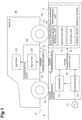
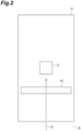
- the electromagnet 41 of the foreign object removal unit 4 having a rectangular shape in plan view is installed such that a route D by which the vehicle 30 travels straight forward or backward and reaches the power transmission unit 2 in the central portion of the parking space P on the road surface S and the long side of the electromagnet are orthogonal to each other.
- the electromagnet 41 of the foreign object removal unit 4 can remove the foreign object from the vehicle-body undersurface 32 by attracting the foreign object to the electromagnet 41 from the vehicle-body undersurface 32 of the vehicle 30 by the magnetic force of the electromagnet 41.
- the foreign object is a paramagnet such as aluminum
- a magnetic field is generated by the eddy current generated in the foreign object when the foreign object passes through the magnetic field of the electromagnet 41 in accordance with the traveling of the vehicle 30.
- the magnetic force caused by the magnetic field generated by the eddy current repels the magnetic force caused by the magnetic field of the electromagnet 41. Therefore, a force works on the foreign object in a direction opposite to the traveling direction of the vehicle 30. Therefore, even when the foreign object is a paramagnet such as aluminum, the electromagnet 41 of the foreign object removal unit 4 can remove the foreign object from the vehicle-body undersurface 32 by the force working on the foreign object in the direction opposite to the traveling direction of the vehicle 30.
- the detection unit 5 shown in Figure 1 detects an approach of the vehicle 30 to either the power transmission unit 2 or the foreign object removal unit 4.
- the detection unit 5 detects the stopping of the vehicle 30 in the position in which the power transmission unit 2 and the power reception unit 21 face each other.
- the detection unit 5 includes a wireless communication device, and detects the approach, the position, and the stopping of the vehicle 30 by wireless communication with a wireless communication device mounted on the vehicle 30.
- the detection unit 5 may include a distance sensor that measures the distance from the vehicle 30, and may detect the position, the approach, and the stopping of the vehicle 30 on the basis of the measured distance from the vehicle 30.
- the detection unit 5 may include a weight sensor that detects the weight of the vehicle 30 on the road surface S, and may detect the position, the approach, and the stopping of the vehicle 30 on the basis of the detected weight of the vehicle 30.
- the detection unit 5 may include a microphone that detects the engine sound of the vehicle 30, and may detect the position, the approach, and the stopping of the vehicle 30 on the basis of the detected engine sound of the vehicle 30.
- the detection unit 5 may include an ultrasonic sensor that detects ultrasonic waves emitted by a sonar of the vehicle 30, and may detect the position, the approach, and the stopping of the vehicle 30 on the basis of the detected ultrasonic waves of the sonar of the vehicle 30.
- the control unit 6 shown in Figure 1 controls the operation of the foreign object removal device 3.
- the control unit 6 stops the foreign object removal unit 4 when the detection unit 5 is not detecting the approach of the vehicle 30 to either the power transmission unit 2 or the foreign object removal unit 4, and activates the foreign object removal unit 4 when the detection unit 5 detects the approach of the vehicle 30 to either the power transmission unit 2 or the foreign object removal unit 4.
- the control unit 6 stops the activation of the foreign object removal unit 4 when the foreign object removal unit 4 is activated and the detection unit 5 detects the stopping of the vehicle 30 in the position in which the power transmission unit 2 and the power reception unit 21 face each other.
- the control unit 6 is an electronic control unit including a CPU, a ROM, and a RAM, for example, as with the power transmission control unit 14.
- the road surface maintenance unit 7 shown in Figure 1 removes the foreign object that has been removed from the vehicle-body undersurface 32 by the foreign object removal unit 4 and has fallen on the road surface S from the road surface S.
- the road surface maintenance unit 7 has a plurality of electromagnets 71a, 71b, 71c, and 71d obtained by dividing both of the long sides of the electromagnet 41 of the foreign object removal unit 4 having a rectangular shape in plan view, and grooves 72 in the vicinity of both of the short sides of the electromagnet 41.
- the electromagnets 71b, 71c, and 71d generate magnetic force and then stop the generation of the magnetic force in the order of the electromagnet 71b, the electromagnet 71c, and the electromagnet 71d.
- the foreign object A is sequentially moved on the electromagnets 71a, 71b, 71c, and 71d, falls into the groove 72 in the vicinity of the electromagnet 71d, and is removed from the road surface S.
- the road surface maintenance unit 7 may have a recessed portion 73 recessed from the road surface S and housing the electromagnet 41 of the foreign object removal unit 4 on the bottom surface thereof, and a grating 74 covering the upper side of the recessed portion 73.
- the foreign object A removed from the vehicle-body undersurface 32 by the electromagnet 41 falls on the bottom surface of the recessed portion 73 through the grating 74.
- the road surface maintenance unit 7 may remove the foreign object A from the road surface S by any of jetting of gas to the road surface S, jetting of liquid to the road surface S, and mechanical means such as a wiper.
- the power reception device 20 mounted on the vehicle 30 includes the power reception unit 21 and a rectifier 22.
- the power reception device 20 is a device that receives power from the power transmission unit 2 of the power transmission device 1 and supplies the power to a load such as a battery 23 of the vehicle 30.
- the power reception unit 21 is a coil device mounted between four wheels 31 on the vehicle-body undersurface 32 of the vehicle 30.
- the magnetic flux generated in the power transmission unit 2 is interlinked with the power reception unit 21, so that the power reception unit 21 generates induced current.
- the power reception unit 21 wirelessly receives power from the power transmission unit 2.
- the rectifier 22 rectifies AC power received by the power reception unit 21 from the power transmission unit 2 and converts the AC power into the DC power.
- the DC power converted by the rectifier 22 is supplied to the load such as the battery 23 of the vehicle 30.
- the control unit 6 of the foreign object removal device 3 stops the foreign object removal unit 4 (SI).
- the foreign object removal unit 4 stops, the electromagnet 41 of the foreign object removal unit 4 does not generate magnetic force.
- the vehicle 30 in which the foreign object A is adhering to the power reception unit 21 on the vehicle-body undersurface 32 approaches the power transmission unit 2 and the electromagnet 41 of the foreign object removal unit 4 in the parking space P for wireless power transfer.
- the control unit 6 activates the foreign object removal unit 4 (S3).
- the foreign object removal unit 4 When the foreign object removal unit 4 is activated, the electromagnet 41 of the foreign object removal unit 4 generates magnetic force.
- the electromagnet 41 of the foreign object removal unit 4 is installed in the route D by which the vehicle 30 reaches the power transmission unit 2 on the road surface S, and hence the electromagnet 41 removes the foreign object A from the vehicle-body undersurface 32 by attracting the foreign object A to the electromagnet 41 from the vehicle-body undersurface 32 by the magnetic force of the electromagnet 41 when the foreign object A is a ferromagnet such as iron.
- the magnetic field by the eddy current is generated as a result of the foreign object A passing through the magnetic field of the electromagnet 41, a force works on the foreign object A in the direction opposite to the traveling direction of the vehicle 30, and the electromagnet 41 removes the foreign object A from the vehicle-body undersurface 32.
- the control unit 6 stops the activation of the foreign object removal unit 4 (S5).
- the road surface maintenance unit 7 removes the foreign object A that has been removed from the vehicle-body undersurface 32 by the electromagnet 41 of the foreign object removal unit 4 and has fallen on the road surface S from the road surface S (S6). Note that the removal of the foreign object A from the road surface S by the road surface maintenance unit 7 may be performed before the stopping of the vehicle 30 and the foreign object removal unit 4.
- the foreign object removal device 3 that removes the foreign object A on the vehicle-body undersurface 32 of the vehicle 30 traveling the road surface S in the wireless power transfer from the power transmission unit 2 of the power transmission device 1 installed on the road surface S to the power reception unit 21 of the power reception device 20 mounted on the vehicle-body undersurface 32
- the foreign object A on the vehicle-body undersurface 32 is removed by the foreign object removal unit 4 installed on the road surface S around the power transmission unit 2. Therefore, the foreign object A on the power reception unit 21 can be removed and a case where the removed foreign object A falls on the power transmission unit 2 can be reduced.
- the technology of removing the foreign object A by using the coil of the power transmission unit 2 as an electromagnet a case where the coils of the power transmission unit 2 and the power reception unit 21 are installed to face each other in the horizontal direction without installing the coil of the power transmission unit 2 on the road surface S in order to prevent the foreign object A from falling on the coil of the power transmission unit 2 can be conceived.
- the technology of removing the foreign object A by using the coil of the power transmission unit 2 as an electromagnet a case where the shape of the coil of the power transmission unit 2 installed on the road surface S is caused to be a shape in which a central portion thereof is protruding can be conceived.
- the power transmission device 1 when the power transmission device 1 is installed on the road surface S of the parking space P, it is difficult to install the coils of the power transmission unit 2 and the power reception unit 21 to face each other in the horizontal direction and cause the shapes of the coils of the power transmission unit 2 and the power transmission unit 2 to be shapes in which central portions thereof are protruding. Therefore, it is difficult to prevent the foreign object A removed from the power reception unit 21 from falling on the power transmission unit 2. Meanwhile, in this embodiment, the foreign object removal unit 4 is installed on the road surface S around the power transmission unit 2, and hence the foreign object A on the power reception unit 21 can be removed and a case where the removed foreign object A falls on the power transmission unit 2 can be reduced.
- the foreign object removal unit 4 has the electromagnet 41 installed on the road surface S, and hence the foreign object A on the vehicle-body undersurface 32 can be removed by a simple configuration.
- the approach of the vehicle 30 to either the power transmission unit 2 or the foreign object removal unit 4 is detected by the detection unit 5.
- the foreign object removal unit 4 is stopped when the detection unit 5 is not detecting the approach of the vehicle 30 to either the power transmission unit 2 or the foreign object removal unit 4, and the foreign object removal unit 4 is activated when the detection unit 5 detects the approach of the vehicle 30 to either the power transmission unit 2 or the foreign object removal unit 4. Therefore, it is possible to activate the foreign object removal unit 4 only when necessary, and the energy consumed by the foreign object removal unit 4 can be reduced.
- the stopping of the vehicle 30 in the position in which the power transmission unit 2 and the power reception unit 21 face each other is detected by the detection unit 5.
- the detection unit 5 When the foreign object removal unit 4 is activated and the stopping of the vehicle 30 in the position in which the power transmission unit 2 and the power reception unit 21 face each other is detected by the detection unit 5, the power transmission unit 2 and the power reception unit 21 are facing each other, and the removal of the foreign object A adhering to the power reception unit 21 by the foreign object removal unit 4 installed on the road surface S around the power transmission unit 2 becomes difficult. Therefore, the activation of the foreign object removal unit 4 by the control unit 6 is stopped. As a result, the foreign object removal unit 4 is activated only when a possibility that the foreign object removal unit 4 can remove the foreign object A is high, and the energy consumed by the foreign object removal unit 4 can be reduced.
- the foreign object A that has been removed from the vehicle-body undersurface 32 by the foreign object removal unit 4 and has fallen on the road surface S is removed from the road surface S by the road surface maintenance unit 7, and hence a case where the foreign object A removed from the vehicle-body undersurface 32 by the foreign object removal unit 4 comes into contact with the power transmission unit 2 on the road surface S by wind and the like can be reduced.
- the foreign object removal unit 4 is installed in the route D by which the vehicle 30 reaches the power transmission unit 2 on the road surface S, and hence the foreign object on the vehicle-body undersurface 32 can be removed more reliably before the wireless power transfer.
- the position in which the foreign object removal unit 4 is installed may be changed, as appropriate.
- the electromagnets 41 of the foreign object removal unit 4 may be installed in all positions around the power transmission unit 2 in order to correspond to a plurality of the routes D of the vehicles 30.
- the control unit 6 it is possible for the control unit 6 to activate only the electromagnet 41 on the route D of the vehicle 30 detected by the detection unit 5.
- the electromagnets 41 of the foreign object removal unit 4 may be installed in positions around the power transmission unit 2 except for that of the road shoulder B.
- the electromagnets 41 of the foreign object removal unit 4 may be installed in positions around the power transmission unit 2 except for that of the wall W.
- the foreign object removal unit 4 may include a brush that abuts against the vehicle-body undersurface 32 and removes the foreign object A.
- the foreign object removal unit 4 may include a nozzle that removes the foreign object A by jetting out gas and liquid to the vehicle-body undersurface 32.
- the foreign object removal unit 4 may include a permanent magnet.
- the road surface maintenance unit 7 may be a groove installed to be adjacent to the power transmission unit 2 around the power transmission unit 2.
- control unit 6 does not necessarily need to stop the activation of the foreign object removal unit 4 when the foreign object removal unit 4 is activated and the detection unit 5 detects the stopping of the vehicle 30.
- the control unit 6 may continue the activation of the foreign object removal unit 4 when the detection unit 5 detects any of the stopping, the passing, and the reciprocal motion of the vehicle 30 above the foreign object removal unit 4, and the control unit 6 may stop the activation of the foreign object removal unit 4 when the detection unit 5 detects the separation of the vehicle 30 from the foreign object removal unit 4.
- the foreign object on the power reception unit can be removed and a case where the removed foreign object falls on the power transmission unit can be reduced.
Landscapes
- Engineering & Computer Science (AREA)
- Power Engineering (AREA)
- Computer Networks & Wireless Communication (AREA)
- Mechanical Engineering (AREA)
- Transportation (AREA)
- Electric Propulsion And Braking For Vehicles (AREA)
- Charge And Discharge Circuits For Batteries Or The Like (AREA)
- Current-Collector Devices For Electrically Propelled Vehicles (AREA)
Abstract
Description
- The present disclosure relates to a foreign object removal device and a power transmission device.
- Technology relating to wireless power transfer from a power transmission unit of a power transmission device installed on a road surface of a parking lot and the like to a power reception unit of a power reception device mounted on a vehicle-body undersurface of a vehicle traveling the road surface is known. By chewing gum and oil, metal foreign objects such as a wrapping paper of the chewing gum may adhere to the power reception unit on the vehicle-body undersurface of the vehicle. When a metal foreign object adheres to the power reception unit, the temperature around the foreign object may rise and the power transmission efficiency of the wireless power transfer may decrease. Thus, in
Patent Literature 1, for example, technology of removing a foreign object by using a coil of a power transmission unit as an electromagnet by causing a direct current to flow through the coil of the power transmission unit when a coil of a power reception unit is in a nonenergized state in wireless power transfer is disclosed. - [Patent Literature 1]
Japanese Unexamined Patent Publication No. 2018-57194 - Incidentally, in the abovementioned technology, when the power transmission unit is installed on the road surface of the parking lot and the like and the power reception unit is mounted on the vehicle-body undersurface of the vehicle traveling the road surface, a foreign object may fall on the power transmission unit that has removed the foreign object from the power reception unit as the electromagnet. The temperature around the foreign object may rise and the power transmission efficiency of the wireless power transfer may decrease also when a metal foreign object is present on the power transmission unit.
- Therefore, the present disclosure describes a power transmission device and a foreign object removal device capable of removing a foreign object on a power reception unit and reducing a case where the removed foreign object falls on a power transmission unit.
- A foreign object removal device according to one aspect of the present disclosure is a foreign object removal device removing a foreign object on a vehicle-body undersurface of a vehicle traveling a road surface in wireless power transfer from a power transmission unit of a power transmission device installed on the road surface to a power reception unit of a power reception device mounted on the vehicle-body undersurface, the foreign object removal device comprising a foreign object removal unit installed on the road surface around the power transmission unit and removing the foreign object on the vehicle-body undersurface.
- According to the foreign object removal device and the power transmission device of the present disclosure, the foreign object on the power reception unit can be removed and a case where the removed foreign object falls on the power transmission unit can be reduced.
-
- [
Figure 1] Figure 1 is a block diagram showing a foreign object removal device and a power transmission device according to an embodiment. - [
Figure 2] Figure 2 is a plan view showing the arrangement of a power transmission unit and an electromagnet with respect to a route of a vehicle in a parking space. - [
Figure 3] Figure 3(A) is a plan view showing one mode of a road surface maintenance unit, andFigure 3(B) is a plan view showing another mode of the road surface maintenance unit. - [
Figure 4] Figure 4 is a flowchart showing the operation of the foreign object removal device according to the embodiment. - [
Figure 5] Figure 5(A), Figure 5(B), and Figure 5(C) are side views showing the operation of the foreign object removal device according to the embodiment. - [
Figure 6] Figure 6(A), Figure 6(B), and Figure 6(C) are plan views showing other examples of the arrangement of the power transmission unit and the electromagnets with respect to routes of the vehicle in the parking space. - A foreign object removal device according to one aspect of the present disclosure is a foreign object removal device removing a foreign object on a vehicle-body undersurface of a vehicle traveling a road surface in wireless power transfer from a power transmission unit of a power transmission device installed on the road surface to a power reception unit of a power reception device mounted on the vehicle-body undersurface, the foreign object removal device comprising a foreign object removal unit installed on the road surface around the power transmission unit and removing the foreign object on the vehicle-body undersurface.
- According to this foreign object removal device, in the foreign object removal device that removes the foreign object on the vehicle-body undersurface in the wireless power transfer from the power transmission unit of the power transmission device installed on the road surface to the power reception unit of the power reception device mounted on the vehicle undersurface traveling the road surface, the foreign object on the vehicle-body undersurface is removed by the foreign object removal unit installed on the road surface around the power transmission unit. Therefore, the foreign object on the power reception unit can be removed and a case where the removed foreign object falls on the power transmission unit can be reduced.
- In some modes, the foreign object removal unit may have an electromagnet installed on the road surface.
- According to this configuration, the foreign object removal unit has the electromagnet installed on the road surface, and hence the foreign object on the vehicle-body undersurface can be removed by a simple configuration.
- In some modes, a detection unit detecting an approach of the vehicle to either the power transmission unit or the foreign object removal unit, and a control unit stopping the foreign object removal unit when the detection unit is not detecting the approach of the vehicle to either the power transmission unit or the foreign object removal unit, and activating the foreign object removal unit when the detection unit detects the approach of the vehicle to either the power transmission unit or the foreign object removal unit may be further comprised.
- According to this configuration, the approach of the vehicle to either the power transmission unit or the foreign object removal unit is detected by the detection unit. By the control unit, the foreign object removal unit is stopped when the detection unit is not detecting the approach of the vehicle to either the power transmission unit or the foreign object removal unit, and the foreign object removal unit is activated when the detection unit detects the approach of the vehicle to either the power transmission unit or the foreign object removal unit. Therefore, it is possible to activate the foreign object removal unit only when necessary, and the energy consumed by the foreign object removal unit can be reduced.
- In some modes, the detection unit may detect stopping of the vehicle in a position in which the power transmission unit and the power reception unit face each other, and the control unit may stop activation of the foreign object removal unit when the foreign object removal unit is activated and the detection unit detects stopping of the vehicle in the position in which the power transmission unit and the power reception unit face each other.
- According to this configuration, the stopping of the vehicle in the position in which the power transmission unit and the power reception unit face each other is detected by the detection unit. When the foreign object removal unit is activated and the stopping of the vehicle in the position in which the power transmission unit and the power reception unit face each other is detected by the detection unit, the power transmission unit and the power reception unit are facing each other, and the removal of the foreign object adhering to the power reception unit by the foreign object removal unit installed on the road surface around the power transmission unit becomes difficult. Therefore, the activation of the foreign object removal unit is stopped by the control unit. As a result, it is possible to activate the foreign object removal unit only when the possibility that the foreign object removal unit can remove the foreign object is high, and the energy consumed by the foreign object removal unit can be reduced.
- In some modes, a road surface maintenance unit removing the foreign object that has been removed from the vehicle-body undersurface by the foreign object removal unit and has fallen on the road surface from the road surface may be further comprised.
- According to this configuration, the foreign object that has been removed from the vehicle-body undersurface by the foreign object removal unit and has fallen on the road surface is removed from the road surface by the road surface maintenance unit, and hence a case where the foreign object removed from the vehicle-body undersurface by the foreign object removal unit comes into contact with the power transmission unit on the road surface by wind and the like can be reduced.
- In some modes, the foreign object removal unit may be installed in a route by which the vehicle reaches the power transmission unit on the road surface.
- According to this configuration, the foreign object removal unit is installed in the route by which the vehicle reaches the power transmission unit on the road surface, and hence the foreign object on the vehicle-body undersurface can be removed more reliably before the wireless power transfer.
- A power transmission device according to another aspect of the present disclosure comprises: the foreign object removal device according to one aspect of the present disclosure; and the power transmission unit.
- An embodiment of the present disclosure is described below with reference to the drawings.
- As shown in
Figure 1 , apower transmission device 1 according to a first embodiment includes apower transmission unit 2 and a foreignobject removal device 3. Thepower transmission device 1 supplies power to apower reception unit 21 of apower reception device 20 mounted on a vehicle-body undersurface 32 of avehicle 30 traveling a road surface S from thepower transmission unit 2 of thepower transmission device 1 installed on the road surface S by wireless power transfer. Thepower transmission device 1 is installed in, for example, a parking space of a parking lot. - The
vehicle 30 is, for example, an electric motor vehicle. Thepower transmission device 1 is configured to supply power to thepower reception device 20 mounted on thevehicle 30 such as an electric motor vehicle that has arrived at the parking space of the parking lot and the like with use of magnetic coupling between coils by a magnetic field resonance method, an electromagnetic induction method, and the like. Note that thevehicle 30 may be various mobile objects such as a plug-in hybrid vehicle or an underwater vehicle instead of the electric motor vehicle. Thevehicle 30 may be an automated guided vehicle (AGV) instead of a manned vehicle. - As shown in
Figure 1 , thepower transmission device 1 includes thepower transmission unit 2, the foreignobject removal device 3, aconverter 12, aninverter 13, and a powertransmission control unit 14. Thepower transmission device 1 is supplied with power from anexternal power source 11. Thepower source 11 supplies power necessary for generating power to be transmitted to thevehicle 30, and supplies single-phase AC power like a commercial AC power source, for example. Note that thepower source 11 is not limited to a single-phase AC power source and may be a power source that supplies three-phase AC power. - The
converter 12 is an AC/DC converter that rectifies the AC power supplied from thepower source 11 and converts the AC power into DC power. Theconverter 12 may have a power factor correction (PFC) function and a back-boost function. Note that a DC power source such as a fuel cell or a solar battery can be used as thepower source 11, and theconverter 12 can be omitted in that case. When thepower source 11 is a DC power source, a DC/DC converter may be provided instead of theconverter 12. Theinverter 13 converts the DC power from theconverter 12 into AC power (high frequency power) of which frequency is higher than that of the AC power of thepower source 11 and supplies the AC power (high frequency power) to thepower transmission unit 2. - The power
transmission control unit 14 is an electronic control unit including, for example, a central processing unit (CPU), a read only memory (ROM), and a random access memory (RAM). The powertransmission control unit 14 controls power supply from thepower transmission unit 2 of thepower transmission device 1 to thepower reception unit 21 of thepower reception device 20. The powertransmission control unit 14 controls the operations of theconverter 12 and theinverter 13 to change the magnitude of the power transmitted from thepower transmission unit 2 of thepower transmission device 1 to thepower reception unit 21 of thepower reception device 20. As described below, the powertransmission control unit 14 starts power transmission from a power transmission unit 15 of thepower transmission device 1 to thepower reception unit 21 of thepower reception device 20 when the foreignobject removal device 3 stops the operation of removing a foreign object and the foreign object is removed from the road surface S. - The
power transmission unit 2 is a coil device installed on the road surface S of the parking space of the parking lot and the like. Thepower reception unit 21 of thepower reception device 20 is a coil device mounted on the vehicle-body undersurface 32 of thevehicle 30. An electromagnetic coupling circuit is formed by bringing thepower transmission unit 2 and thepower reception unit 21 close to each other. The electromagnetic coupling circuit refers to a circuit in which thepower transmission unit 2 and thepower reception unit 21 are electromagnetically coupled to each other and power transmission is performed by wireless power transfer from thepower transmission unit 2 to thepower reception unit 21. Note that thepower transmission unit 2 and thepower reception unit 21 may perform wireless power transfer by an electromagnetic induction method or may perform wireless power transfer by a magnetic field resonance method. Thepower transmission unit 2 and thepower reception unit 21 may be antenna devices. - The foreign
object removal device 3 removes a foreign object on the vehicle-body undersurface 32 of thevehicle 30 traveling the road surface S in the wireless power transfer from thepower transmission unit 2 of thepower transmission device 1 installed on the road surface S to thepower reception unit 21 of thepower reception device 20 mounted on the vehicle-body undersurface 32. The foreign object is a metal object that causes heat generation between thepower transmission unit 2 and thepower reception unit 21. The foreign object is, for example, a wrapping paper and the like of confectionery such as a chewing gum adhering to thepower reception unit 21 on the vehicle-body undersurface 32 of thevehicle 30 by the chewing gum, oil, and the like. Note that, when the foreign object is adhering to the vehicle-body undersurface 32, the foreign object adhering to the vehicle-body undersurface 32 may fall on thepower transmission unit 2 and cause heat generation between thepower transmission unit 2 and thepower reception unit 21 even when the foreign object is not adhering to thepower reception unit 21. Therefore, the foreignobject removal device 3 of this embodiment also removes a foreign object adhering to a position other than the position in which thepower reception unit 21 is installed on the vehicle-body undersurface 32. - The foreign
object removal device 3 includes a foreignobject removal unit 4, a detection unit 5, acontrol unit 6, and a roadsurface maintenance unit 7. The foreignobject removal unit 4 is installed on the road surface S around thepower transmission unit 2 and removes the foreign object on the vehicle-body undersurface 32. The expression of "the foreignobject removal unit 4 is installed on the road surface S around thepower transmission unit 2" means that, for example, the foreignobject removal unit 4 is not installed in the same position as thepower transmission unit 2 on the road surface S and is installed in a range from a position adjacent to thepower transmission unit 2 to a position within 10 m from thepower transmission unit 2. The foreignobject removal unit 4 has anelectromagnet 41 installed on the road surface S. The foreignobject removal unit 4 is installed in a route by which thevehicle 30 reaches thepower transmission unit 2 on the road surface S. For example, as shown inFigure 2 , when thepower transmission unit 2 is installed in a central portion of a parking space P of a parking lot, theelectromagnet 41 of the foreignobject removal unit 4 having a rectangular shape in plan view is installed such that a route D by which thevehicle 30 travels straight forward or backward and reaches thepower transmission unit 2 in the central portion of the parking space P on the road surface S and the long side of the electromagnet are orthogonal to each other. - When the foreign object is a ferromagnet such as iron, the
electromagnet 41 of the foreignobject removal unit 4 can remove the foreign object from the vehicle-body undersurface 32 by attracting the foreign object to theelectromagnet 41 from the vehicle-body undersurface 32 of thevehicle 30 by the magnetic force of theelectromagnet 41. When the foreign object is a paramagnet such as aluminum, a magnetic field is generated by the eddy current generated in the foreign object when the foreign object passes through the magnetic field of theelectromagnet 41 in accordance with the traveling of thevehicle 30. The magnetic force caused by the magnetic field generated by the eddy current repels the magnetic force caused by the magnetic field of theelectromagnet 41. Therefore, a force works on the foreign object in a direction opposite to the traveling direction of thevehicle 30. Therefore, even when the foreign object is a paramagnet such as aluminum, theelectromagnet 41 of the foreignobject removal unit 4 can remove the foreign object from the vehicle-body undersurface 32 by the force working on the foreign object in the direction opposite to the traveling direction of thevehicle 30. - The detection unit 5 shown in
Figure 1 detects an approach of thevehicle 30 to either thepower transmission unit 2 or the foreignobject removal unit 4. The detection unit 5 detects the stopping of thevehicle 30 in the position in which thepower transmission unit 2 and thepower reception unit 21 face each other. For example, the detection unit 5 includes a wireless communication device, and detects the approach, the position, and the stopping of thevehicle 30 by wireless communication with a wireless communication device mounted on thevehicle 30. - Note that, for example, the detection unit 5 may include a distance sensor that measures the distance from the
vehicle 30, and may detect the position, the approach, and the stopping of thevehicle 30 on the basis of the measured distance from thevehicle 30. For example, the detection unit 5 may include a weight sensor that detects the weight of thevehicle 30 on the road surface S, and may detect the position, the approach, and the stopping of thevehicle 30 on the basis of the detected weight of thevehicle 30. For example, the detection unit 5 may include a microphone that detects the engine sound of thevehicle 30, and may detect the position, the approach, and the stopping of thevehicle 30 on the basis of the detected engine sound of thevehicle 30. For example, the detection unit 5 may include an ultrasonic sensor that detects ultrasonic waves emitted by a sonar of thevehicle 30, and may detect the position, the approach, and the stopping of thevehicle 30 on the basis of the detected ultrasonic waves of the sonar of thevehicle 30. - The
control unit 6 shown inFigure 1 controls the operation of the foreignobject removal device 3. Thecontrol unit 6 stops the foreignobject removal unit 4 when the detection unit 5 is not detecting the approach of thevehicle 30 to either thepower transmission unit 2 or the foreignobject removal unit 4, and activates the foreignobject removal unit 4 when the detection unit 5 detects the approach of thevehicle 30 to either thepower transmission unit 2 or the foreignobject removal unit 4. Thecontrol unit 6 stops the activation of the foreignobject removal unit 4 when the foreignobject removal unit 4 is activated and the detection unit 5 detects the stopping of thevehicle 30 in the position in which thepower transmission unit 2 and thepower reception unit 21 face each other. Thecontrol unit 6 is an electronic control unit including a CPU, a ROM, and a RAM, for example, as with the powertransmission control unit 14. - The road
surface maintenance unit 7 shown inFigure 1 removes the foreign object that has been removed from the vehicle-body undersurface 32 by the foreignobject removal unit 4 and has fallen on the road surface S from the road surface S. As shown inFigure 3(A) , for example, the roadsurface maintenance unit 7 has a plurality ofelectromagnets electromagnet 41 of the foreignobject removal unit 4 having a rectangular shape in plan view, andgrooves 72 in the vicinity of both of the short sides of theelectromagnet 41. For example, when a foreign object A removed from the vehicle-body undersurface 32 by theelectromagnet 41 falls on theelectromagnet 71a, theelectromagnets electromagnet 71b, theelectromagnet 71c, and theelectromagnet 71d. As a result, the foreign object A is sequentially moved on theelectromagnets groove 72 in the vicinity of theelectromagnet 71d, and is removed from the road surface S. - As shown in
Figure 3(B) , for example, the roadsurface maintenance unit 7 may have a recessedportion 73 recessed from the road surface S and housing theelectromagnet 41 of the foreignobject removal unit 4 on the bottom surface thereof, and a grating 74 covering the upper side of the recessedportion 73. For example, the foreign object A removed from the vehicle-body undersurface 32 by theelectromagnet 41 falls on the bottom surface of the recessedportion 73 through thegrating 74. As a result, the foreign object A is removed from the road surface S. Note that the roadsurface maintenance unit 7 may remove the foreign object A from the road surface S by any of jetting of gas to the road surface S, jetting of liquid to the road surface S, and mechanical means such as a wiper. - Meanwhile, the
power reception device 20 mounted on thevehicle 30 includes thepower reception unit 21 and arectifier 22. Thepower reception device 20 is a device that receives power from thepower transmission unit 2 of thepower transmission device 1 and supplies the power to a load such as abattery 23 of thevehicle 30. As described above, thepower reception unit 21 is a coil device mounted between fourwheels 31 on the vehicle-body undersurface 32 of thevehicle 30. The magnetic flux generated in thepower transmission unit 2 is interlinked with thepower reception unit 21, so that thepower reception unit 21 generates induced current. As a result, thepower reception unit 21 wirelessly receives power from thepower transmission unit 2. Therectifier 22 rectifies AC power received by thepower reception unit 21 from thepower transmission unit 2 and converts the AC power into the DC power. The DC power converted by therectifier 22 is supplied to the load such as thebattery 23 of thevehicle 30. - The operations of the
power transmission device 1 and the foreignobject removal device 3 of this embodiment are described below. As shown inFigure 4 , when the detection unit 5 is not detecting the approach of thevehicle 30 to either thepower transmission unit 2 or the foreignobject removal unit 4, thecontrol unit 6 of the foreignobject removal device 3 stops the foreign object removal unit 4 (SI). When the foreignobject removal unit 4 is stopped, theelectromagnet 41 of the foreignobject removal unit 4 does not generate magnetic force. As shown inFigure 5(A) , thevehicle 30 in which the foreign object A is adhering to thepower reception unit 21 on the vehicle-body undersurface 32 approaches thepower transmission unit 2 and theelectromagnet 41 of the foreignobject removal unit 4 in the parking space P for wireless power transfer. As shown inFigure 4 , when the detection unit 5 detects the approach of thevehicle 30 to either thepower transmission unit 2 or the foreign object removal unit 4 (S2), thecontrol unit 6 activates the foreign object removal unit 4 (S3). When the foreignobject removal unit 4 is activated, theelectromagnet 41 of the foreignobject removal unit 4 generates magnetic force. - As shown in
Figure 2 ,Figure 5(A), and Figure 5(B) , theelectromagnet 41 of the foreignobject removal unit 4 is installed in the route D by which thevehicle 30 reaches thepower transmission unit 2 on the road surface S, and hence theelectromagnet 41 removes the foreign object A from the vehicle-body undersurface 32 by attracting the foreign object A to theelectromagnet 41 from the vehicle-body undersurface 32 by the magnetic force of theelectromagnet 41 when the foreign object A is a ferromagnet such as iron. Even when the foreign object A is a paramagnet such as aluminum, as described above, the magnetic field by the eddy current is generated as a result of the foreign object A passing through the magnetic field of theelectromagnet 41, a force works on the foreign object A in the direction opposite to the traveling direction of thevehicle 30, and theelectromagnet 41 removes the foreign object A from the vehicle-body undersurface 32. - As shown in
Figure 4 andFigure 5(C) , when the foreignobject removal unit 4 is activated and the detection unit 5 detects the stopping of thevehicle 30 in the position in which thepower transmission unit 2 and thepower reception unit 21 face each other (S4), thecontrol unit 6 stops the activation of the foreign object removal unit 4 (S5). The roadsurface maintenance unit 7 removes the foreign object A that has been removed from the vehicle-body undersurface 32 by theelectromagnet 41 of the foreignobject removal unit 4 and has fallen on the road surface S from the road surface S (S6). Note that the removal of the foreign object A from the road surface S by the roadsurface maintenance unit 7 may be performed before the stopping of thevehicle 30 and the foreignobject removal unit 4. As shown inFigure 4 andFigure 5(C) , wireless power transfer from thepower transmission unit 2 of thepower transmission device 1 installed on the road surface S to thepower reception unit 21 of thepower reception device 20 mounted on the vehicle-body undersurface 32 of thevehicle 30 is performed (S7). - According to this embodiment, in the foreign
object removal device 3 that removes the foreign object A on the vehicle-body undersurface 32 of thevehicle 30 traveling the road surface S in the wireless power transfer from thepower transmission unit 2 of thepower transmission device 1 installed on the road surface S to thepower reception unit 21 of thepower reception device 20 mounted on the vehicle-body undersurface 32, the foreign object A on the vehicle-body undersurface 32 is removed by the foreignobject removal unit 4 installed on the road surface S around thepower transmission unit 2. Therefore, the foreign object A on thepower reception unit 21 can be removed and a case where the removed foreign object A falls on thepower transmission unit 2 can be reduced. - For example, in the technology of removing the foreign object A by using the coil of the
power transmission unit 2 as an electromagnet, a case where the coils of thepower transmission unit 2 and thepower reception unit 21 are installed to face each other in the horizontal direction without installing the coil of thepower transmission unit 2 on the road surface S in order to prevent the foreign object A from falling on the coil of thepower transmission unit 2 can be conceived. In the technology of removing the foreign object A by using the coil of thepower transmission unit 2 as an electromagnet, a case where the shape of the coil of thepower transmission unit 2 installed on the road surface S is caused to be a shape in which a central portion thereof is protruding can be conceived. However, when thepower transmission device 1 is installed on the road surface S of the parking space P, it is difficult to install the coils of thepower transmission unit 2 and thepower reception unit 21 to face each other in the horizontal direction and cause the shapes of the coils of thepower transmission unit 2 and thepower transmission unit 2 to be shapes in which central portions thereof are protruding. Therefore, it is difficult to prevent the foreign object A removed from thepower reception unit 21 from falling on thepower transmission unit 2. Meanwhile, in this embodiment, the foreignobject removal unit 4 is installed on the road surface S around thepower transmission unit 2, and hence the foreign object A on thepower reception unit 21 can be removed and a case where the removed foreign object A falls on thepower transmission unit 2 can be reduced. - According to this embodiment, the foreign
object removal unit 4 has theelectromagnet 41 installed on the road surface S, and hence the foreign object A on the vehicle-body undersurface 32 can be removed by a simple configuration. - According to this embodiment, the approach of the
vehicle 30 to either thepower transmission unit 2 or the foreignobject removal unit 4 is detected by the detection unit 5. By the control unit, the foreignobject removal unit 4 is stopped when the detection unit 5 is not detecting the approach of thevehicle 30 to either thepower transmission unit 2 or the foreignobject removal unit 4, and the foreignobject removal unit 4 is activated when the detection unit 5 detects the approach of thevehicle 30 to either thepower transmission unit 2 or the foreignobject removal unit 4. Therefore, it is possible to activate the foreignobject removal unit 4 only when necessary, and the energy consumed by the foreignobject removal unit 4 can be reduced. - According to this embodiment, the stopping of the
vehicle 30 in the position in which thepower transmission unit 2 and thepower reception unit 21 face each other is detected by the detection unit 5. When the foreignobject removal unit 4 is activated and the stopping of thevehicle 30 in the position in which thepower transmission unit 2 and thepower reception unit 21 face each other is detected by the detection unit 5, thepower transmission unit 2 and thepower reception unit 21 are facing each other, and the removal of the foreign object A adhering to thepower reception unit 21 by the foreignobject removal unit 4 installed on the road surface S around thepower transmission unit 2 becomes difficult. Therefore, the activation of the foreignobject removal unit 4 by thecontrol unit 6 is stopped. As a result, the foreignobject removal unit 4 is activated only when a possibility that the foreignobject removal unit 4 can remove the foreign object A is high, and the energy consumed by the foreignobject removal unit 4 can be reduced. - According to this embodiment, the foreign object A that has been removed from the vehicle-
body undersurface 32 by the foreignobject removal unit 4 and has fallen on the road surface S is removed from the road surface S by the roadsurface maintenance unit 7, and hence a case where the foreign object A removed from the vehicle-body undersurface 32 by the foreignobject removal unit 4 comes into contact with thepower transmission unit 2 on the road surface S by wind and the like can be reduced. - According to this embodiment, the foreign
object removal unit 4 is installed in the route D by which thevehicle 30 reaches thepower transmission unit 2 on the road surface S, and hence the foreign object on the vehicle-body undersurface 32 can be removed more reliably before the wireless power transfer. - The embodiment and the modification of the present disclosure have been described above, but the present disclosure is not limited to the abovementioned embodiment. For example, the position in which the foreign
object removal unit 4 is installed may be changed, as appropriate. For example, as shown inFigure 6(A) , when thevehicle 30 can reach thepower transmission unit 2 installed on the road surface S of the parking space P from all directions, theelectromagnets 41 of the foreignobject removal unit 4 may be installed in all positions around thepower transmission unit 2 in order to correspond to a plurality of the routes D of thevehicles 30. In this case, as shown inFigure 6(A) by diagonal lines, it is possible for thecontrol unit 6 to activate only theelectromagnet 41 on the route D of thevehicle 30 detected by the detection unit 5. - For example, as shown in
Figure 6(B) , when the parking space P is disposed to be adjacent to a road shoulder B and thevehicle 30 can reach thepower transmission unit 2 installed on the road surface S of the parking space P from directions other than that of the road shoulder B, theelectromagnets 41 of the foreignobject removal unit 4 may be installed in positions around thepower transmission unit 2 except for that of the road shoulder B. For example, as shown inFigure 6(C) , when the parking space P is disposed to be adjacent to a wall W and thevehicle 30 can reach thepower transmission unit 2 installed on the road surface S of the parking space P from directions other than that of the wall W, theelectromagnets 41 of the foreignobject removal unit 4 may be installed in positions around thepower transmission unit 2 except for that of the wall W. - For example, the foreign
object removal unit 4 may include a brush that abuts against the vehicle-body undersurface 32 and removes the foreign object A. For example, the foreignobject removal unit 4 may include a nozzle that removes the foreign object A by jetting out gas and liquid to the vehicle-body undersurface 32. For example, the foreignobject removal unit 4 may include a permanent magnet. For example, the roadsurface maintenance unit 7 may be a groove installed to be adjacent to thepower transmission unit 2 around thepower transmission unit 2. - For example, the
control unit 6 does not necessarily need to stop the activation of the foreignobject removal unit 4 when the foreignobject removal unit 4 is activated and the detection unit 5 detects the stopping of thevehicle 30. For example, when the distance between thepower transmission unit 2 and the foreignobject removal unit 4 installed on the road surface S is about several meters, thecontrol unit 6 may continue the activation of the foreignobject removal unit 4 when the detection unit 5 detects any of the stopping, the passing, and the reciprocal motion of thevehicle 30 above the foreignobject removal unit 4, and thecontrol unit 6 may stop the activation of the foreignobject removal unit 4 when the detection unit 5 detects the separation of thevehicle 30 from the foreignobject removal unit 4. - According to the foreign object removal device and the power transmission device of the present disclosure, the foreign object on the power reception unit can be removed and a case where the removed foreign object falls on the power transmission unit can be reduced.
-
- 1
- Power transmission device
- 2
- Power transmission unit
- 3
- Foreign object removal device
- 4
- Foreign object removal unit
- 5
- Detection unit
- 6
- Control unit
- 7
- Road surface maintenance unit
- 11
- Power source
- 12
- Converter
- 13
- Inverter
- 14
- Power transmission control unit
- 20
- Power reception device
- 21
- Power reception unit
- 22
- Rectifier
- 23
- Battery
- 30
- Vehicle
- 31
- Wheel
- 32
- Vehicle-body undersurface
- 41
- Electromagnet
- 71a, 71b, 71c, 71d
- Electromagnet
- 72
- Groove
- 73
- Recessed portion
- 74
- Grating
- S
- Road surface
- P
- Parking space
- D
- Route
- A
- Foreign object
- B
- Road shoulder
- W
- Wall
Claims (7)
- A foreign object removal device removing a foreign object on a vehicle-body undersurface of a vehicle traveling a road surface in wireless power transfer from a power transmission unit of a power transmission device installed on the road surface to a power reception unit of a power reception device mounted on the vehicle-body undersurface, the foreign object removal device comprising a foreign object removal unit installed on the road surface around the power transmission unit and removing the foreign object on the vehicle-body undersurface.
- The foreign object removal device according to claim 1, wherein the foreign object removal unit has an electromagnet installed on the road surface.
- The foreign object removal device according to claim 1 or 2, further comprising:a detection unit detecting an approach of the vehicle to either the power transmission unit or the foreign object removal unit; anda control unit stopping the foreign object removal unit when the detection unit is not detecting the approach of the vehicle to either the power transmission unit or the foreign object removal unit, and activating the foreign object removal unit when the detection unit detects the approach of the vehicle to either the power transmission unit or the foreign object removal unit.
- The foreign object removal device according to claim 3, wherein:the detection unit detects stopping of the vehicle in a position in which the power transmission unit and the power reception unit face each other; andthe control unit stops activation of the foreign object removal unit when the foreign object removal unit is activated and the detection unit detects stopping of the vehicle in the position in which the power transmission unit and the power reception unit face each other.
- The foreign object removal device according to any one of claims 1 to 4, further comprising a road surface maintenance unit removing the foreign object that has been removed from the vehicle-body undersurface by the foreign object removal unit and has fallen on the road surface from the road surface.
- The foreign object removal device according to any one of claims 1 to 5, wherein the foreign object removal unit is installed in a route by which the vehicle reaches the power transmission unit on the road surface.
- A power transmission device, comprising:the foreign object removal device according to any one of claims 1 to 6; andthe power transmission unit.
Applications Claiming Priority (2)
| Application Number | Priority Date | Filing Date | Title |
|---|---|---|---|
| JP2019092010 | 2019-05-15 | ||
| PCT/JP2020/004429 WO2020230380A1 (en) | 2019-05-15 | 2020-02-05 | Foreign object removal device and power transmission device |
Publications (2)
| Publication Number | Publication Date |
|---|---|
| EP3971012A1 true EP3971012A1 (en) | 2022-03-23 |
| EP3971012A4 EP3971012A4 (en) | 2023-04-12 |
Family
ID=73290276
Family Applications (1)
| Application Number | Title | Priority Date | Filing Date |
|---|---|---|---|
| EP20806681.1A Pending EP3971012A4 (en) | 2019-05-15 | 2020-02-05 | Foreign object removal device and power transmission device |
Country Status (4)
| Country | Link |
|---|---|
| US (1) | US20220126709A1 (en) |
| EP (1) | EP3971012A4 (en) |
| JP (1) | JP7222423B2 (en) |
| WO (1) | WO2020230380A1 (en) |
Family Cites Families (8)
| Publication number | Priority date | Publication date | Assignee | Title |
|---|---|---|---|---|
| JP2014023296A (en) * | 2012-07-19 | 2014-02-03 | Panasonic Corp | Power transmission coil |
| JP6060546B2 (en) | 2012-07-26 | 2017-01-18 | 株式会社Ihi | Contactless power supply system |
| CN111152671A (en) * | 2013-11-18 | 2020-05-15 | 株式会社Ihi | Non-contact power supply system |
| CN106232248B (en) | 2014-06-30 | 2019-05-10 | 株式会社Ihi | Ground side apparatus, the contactless power supply system of foreign substance removing apparatus, contactless power supply system |
| WO2016000084A1 (en) * | 2014-07-04 | 2016-01-07 | Elix Wireless Charging Systems Inc. | Wireless power transfer systems having guides for foreign object removal and methods of fabrication and use of same |
| JP2018057194A (en) | 2016-09-30 | 2018-04-05 | パナソニックIpマネジメント株式会社 | Controller of non-contact power transmission system, power transmission unit, power reception unit and non-contact power transmission system |
| JP7049206B2 (en) * | 2018-07-24 | 2022-04-06 | 株式会社ダイヘン | Contactless power supply |
| KR20220043625A (en) * | 2020-09-29 | 2022-04-05 | 한국전자통신연구원 | Wireless charging system for removing the foreign matter, and foreign matter remove method of the apparatus |
-
2020
- 2020-02-05 US US17/429,365 patent/US20220126709A1/en active Pending
- 2020-02-05 JP JP2021519261A patent/JP7222423B2/en active Active
- 2020-02-05 EP EP20806681.1A patent/EP3971012A4/en active Pending
- 2020-02-05 WO PCT/JP2020/004429 patent/WO2020230380A1/en unknown
Also Published As
| Publication number | Publication date |
|---|---|
| EP3971012A4 (en) | 2023-04-12 |
| WO2020230380A1 (en) | 2020-11-19 |
| JPWO2020230380A1 (en) | 2021-11-25 |
| JP7222423B2 (en) | 2023-02-15 |
| US20220126709A1 (en) | 2022-04-28 |
Similar Documents
| Publication | Publication Date | Title |
|---|---|---|
| US9983300B2 (en) | Systems, methods, and apparatus for living object protection in wireless power transfer applications | |
| EP3128524B1 (en) | Power transmission apparatus and power reception apparatus | |
| EP3234639B1 (en) | Radar system with several transceivers for monitoring and detecting targets within a surveillance area | |
| JP6067211B2 (en) | Non-contact power feeding device | |
| US10984946B2 (en) | Reducing magnetic flux density proximate to a wireless charging pad | |
| WO2010090333A1 (en) | Power supply system for moving body, and moving body | |
| JP5906691B2 (en) | Non-contact power transmission device and mobile vehicle | |
| KR20120061085A (en) | Roadway powered electric vehicle system | |
| WO2014184864A1 (en) | Contactless power transmission device and moving vehicle | |
| JP2012178959A (en) | Antenna | |
| WO2013065283A1 (en) | Non-contact charging apparatus | |
| JP6146119B2 (en) | Non-contact power supply system and bag system | |
| JP2015104161A (en) | Non-contact power transmission device and non-contact power transmission system | |
| JP2012178529A (en) | Antenna | |
| EP3971012A1 (en) | Foreign object removal device and power transmission device | |
| JP2011250498A (en) | Non-contact power feeding device | |
| JP6022267B2 (en) | Mobile power supply type non-contact power supply device | |
| JP5903990B2 (en) | Contactless power supply | |
| JP5930182B2 (en) | antenna | |
| JP2016106512A (en) | Non-contact power feeding device | |
| CN107809142A (en) | Use the wireless power transmission control method and equipment of objection detecting sensor | |
| JP5757269B2 (en) | Non-contact power feeding device | |
| JP2014033524A (en) | Non-contact power supply system for unmanned carrier | |
| JP7113317B2 (en) | Power transmitting device, power receiving device, wireless power transmission system, and method for driving power transmitting device | |
| JP2015019453A (en) | Non-contact power supply system |
Legal Events
| Date | Code | Title | Description |
|---|---|---|---|
| STAA | Information on the status of an ep patent application or granted ep patent |
Free format text: STATUS: THE INTERNATIONAL PUBLICATION HAS BEEN MADE |
|
| PUAI | Public reference made under article 153(3) epc to a published international application that has entered the european phase |
Free format text: ORIGINAL CODE: 0009012 |
|
| STAA | Information on the status of an ep patent application or granted ep patent |
Free format text: STATUS: REQUEST FOR EXAMINATION WAS MADE |
|
| 17P | Request for examination filed |
Effective date: 20210714 |
|
| AK | Designated contracting states |
Kind code of ref document: A1 Designated state(s): AL AT BE BG CH CY CZ DE DK EE ES FI FR GB GR HR HU IE IS IT LI LT LU LV MC MK MT NL NO PL PT RO RS SE SI SK SM TR |
|
| DAV | Request for validation of the european patent (deleted) | ||
| DAX | Request for extension of the european patent (deleted) | ||
| REG | Reference to a national code |
Ref country code: DE Ref legal event code: R079 Free format text: PREVIOUS MAIN CLASS: B60L0005000000 Ipc: H02J0050600000 |
|
| A4 | Supplementary search report drawn up and despatched |
Effective date: 20230314 |
|
| RIC1 | Information provided on ipc code assigned before grant |
Ipc: H02J 7/00 20060101ALI20230307BHEP Ipc: H02J 50/10 20160101ALI20230307BHEP Ipc: B60L 53/124 20190101ALI20230307BHEP Ipc: H02J 50/90 20160101ALI20230307BHEP Ipc: H02J 50/60 20160101AFI20230307BHEP |