EP3970888A2 - Cutting element, rotary tool and lathe therewith and method and use - Google Patents
Cutting element, rotary tool and lathe therewith and method and use Download PDFInfo
- Publication number
- EP3970888A2 EP3970888A2 EP21193215.7A EP21193215A EP3970888A2 EP 3970888 A2 EP3970888 A2 EP 3970888A2 EP 21193215 A EP21193215 A EP 21193215A EP 3970888 A2 EP3970888 A2 EP 3970888A2
- Authority
- EP
- European Patent Office
- Prior art keywords
- tool
- axis
- cutting element
- turning
- workpiece
- Prior art date
- Legal status (The legal status is an assumption and is not a legal conclusion. Google has not performed a legal analysis and makes no representation as to the accuracy of the status listed.)
- Pending
Links
Images


Classifications
-
- B—PERFORMING OPERATIONS; TRANSPORTING
- B23—MACHINE TOOLS; METAL-WORKING NOT OTHERWISE PROVIDED FOR
- B23B—TURNING; BORING
- B23B27/00—Tools for turning or boring machines; Tools of a similar kind in general; Accessories therefor
- B23B27/14—Cutting tools of which the bits or tips or cutting inserts are of special material
- B23B27/141—Specially shaped plate-like cutting inserts, i.e. length greater or equal to width, width greater than or equal to thickness
- B23B27/145—Specially shaped plate-like cutting inserts, i.e. length greater or equal to width, width greater than or equal to thickness characterised by having a special shape
-
- B—PERFORMING OPERATIONS; TRANSPORTING
- B28—WORKING CEMENT, CLAY, OR STONE
- B28D—WORKING STONE OR STONE-LIKE MATERIALS
- B28D1/00—Working stone or stone-like materials, e.g. brick, concrete or glass, not provided for elsewhere; Machines, devices, tools therefor
- B28D1/16—Working stone or stone-like materials, e.g. brick, concrete or glass, not provided for elsewhere; Machines, devices, tools therefor by turning
-
- B—PERFORMING OPERATIONS; TRANSPORTING
- B23—MACHINE TOOLS; METAL-WORKING NOT OTHERWISE PROVIDED FOR
- B23B—TURNING; BORING
- B23B2200/00—Details of cutting inserts
- B23B2200/04—Overall shape
- B23B2200/0423—Irregular
-
- B—PERFORMING OPERATIONS; TRANSPORTING
- B23—MACHINE TOOLS; METAL-WORKING NOT OTHERWISE PROVIDED FOR
- B23B—TURNING; BORING
- B23B2200/00—Details of cutting inserts
- B23B2200/20—Top or side views of the cutting edge
- B23B2200/202—Top or side views of the cutting edge with curved cutting edge
-
- B—PERFORMING OPERATIONS; TRANSPORTING
- B23—MACHINE TOOLS; METAL-WORKING NOT OTHERWISE PROVIDED FOR
- B23B—TURNING; BORING
- B23B2226/00—Materials of tools or workpieces not comprising a metal
- B23B2226/31—Diamond
- B23B2226/315—Diamond polycrystalline [PCD]
-
- B—PERFORMING OPERATIONS; TRANSPORTING
- B23—MACHINE TOOLS; METAL-WORKING NOT OTHERWISE PROVIDED FOR
- B23B—TURNING; BORING
- B23B27/00—Tools for turning or boring machines; Tools of a similar kind in general; Accessories therefor
- B23B27/14—Cutting tools of which the bits or tips or cutting inserts are of special material
- B23B27/18—Cutting tools of which the bits or tips or cutting inserts are of special material with cutting bits or tips or cutting inserts rigidly mounted, e.g. by brazing
- B23B27/20—Cutting tools of which the bits or tips or cutting inserts are of special material with cutting bits or tips or cutting inserts rigidly mounted, e.g. by brazing with diamond bits or cutting inserts
Definitions
- the invention relates to a cutting element according to the preamble of claim 1, a turning tool with it according to claim 8, a lathe with one of the two according to claim 11, methods according to claims 12 and 13 and a use according to claim 15, each using the cutting element according to claim 1.
- Turning methods with turning machines are known for carrying out machining methods with geometrically defined cutting edges.
- By rotating a workpiece around an axis of rotation its surface is guided past a tool cutting edge of a cutting element and the chip is lifted off.
- the other movements to create the cut are usually much slower and shorter and are usually implemented by the degrees of freedom of the turning tool.
- One form of turning is cross facing. With transverse facing, the cutting edge of the tool moves transversely to the axis of rotation. In practice, it is also referred to as face turning. The turning result is a flat face on the workpiece.
- a relative A special form of transverse face turning is used in the manufacture of optical lens surfaces. Such is, for example, in DE 10 2011 053 772 B3 described.
- a front side of a lens blank is traversed from the outside in towards the axis of rotation with the cutting edge of the tool.
- the rotation of the workpiece results in a spiral working path that the cutting edge of the tool covers on the workpiece.
- the transverse movement of the cutting edge is also superimposed by a longitudinal movement parallel to the axis of rotation.
- a disadvantage of the previously known solutions is the slow production speed when carrying out the turning process, due to tool radii of approximately 2 mm and the associated high number of revolutions for traversing the entire surface.
- the rotation speed cannot be increased at will. Accordingly, the production volume of the lathe is low.
- the price of spectacle lenses has to be reduced for economic reasons.
- the solution should work reliably, have high manufacturing precision and be inexpensive to implement. If possible, customers of existing machines should also benefit from the solution.
- the invention relates to a cutting element for a lathe for cutting technology, with a tool cutting edge, which consists of a first material, which intersects a (geometric) tool axis of the cutting element at a vertical angle (geometrically), is aligned, has a tool radius based on a circle center, wherein the center of the circle lies on the tool axis and has an included angle relative to the center of the circle.
- the tool radius is between 3.0 mm and 7.0 mm, preferably between 4.0 mm and 6.0 mm, and particularly preferably between 4.5 mm and 5.5 mm, that the tool cutting edge has an opening angle relative to the center of the circle, which is a maximum of 90 degrees, preferably a maximum of 70 degrees, more preferably a maximum of 60 degrees, and particularly preferably a maximum of 55 degrees, and that the cutting element has an asymmetry such that the tool axis intersects the opening angle eccentrically (geometrically).
- the advantage of this is that the productivity can be increased by increasing the radius of the turning tool compared to the radii of up to 2.0 mm used in the prior art for producing spectacle lenses. This is achieved in particular by reducing the number of revolutions required to process the surface.
- the spiral path width is increased by means of the tool radius of over 3.0 mm without significantly changing the turned surface structure (peak height) in order to be able to polish the later glasses with the standard parameters.
- the asymmetry avoids destructive contacts between the cutting edge of the tool and surface areas that are not intended to be removed during the manufacture of spectacle lenses, although the comparatively large radius of the cutting edge of the tool is used.
- the spiral pitch width increases from 0.033 mm to 0.053 mm when processing a lens blank, while the number of revolutions for a typical lens blank diameter of 65 mm decreases Approximately 2,000 to 1,250 revolutions, with a manufactured peak height between the spiral turns being limited to 0.07 ⁇ m.
- This 5 mm appears to be the ideal tool radius in eyeglass lens production, with which a large number of lenses can be quickly manufactured. can be edited.
- the peak heights can also be polished with at least almost the same effort when using the cutting element according to the invention.
- the turning process time is reduced by around 37.5% in accordance with the required number of revolutions at the same rotational speed.
- the cutting element according to the invention can also be used without mechanical or control engineering conversion in many Use existing machines so that the solution can be retrofitted in a customer-friendly manner.
- the first material is a synthetic diamond material, in particular from the group of polycrystalline diamond (PCD), chemical vapor deposition (CVD), synthetic monocrystalline diamond (MKD) and aggregated diamond nanorods (ADNR), or polycrystalline cubic boron nitride (CBN) , or a natural diamond (ND).
- PCD polycrystalline diamond
- CVD chemical vapor deposition
- MKD synthetic monocrystalline diamond
- ADNR aggregated diamond nanorods
- CBN polycrystalline cubic boron nitride
- ND natural diamond
- the asymmetry is designed in such a way that a longer section of the tool cutting edge is arranged on a first side of the tool axis than on the opposite, second side of the tool axis.
- This enables different machining depending on the feed movement of the tool cutting edge. This is particularly helpful with curved machining surfaces in order to avoid collisions of the cutting element off the spiral path and thus unintentionally remove material.
- the cutting element is less expensive than if it were to extend equally far from the tool axis on both sides. When working on sloping surfaces, the section of the cutting element pointing down the valley is used far less or not at all than the section pointing up the hill and can therefore be omitted.
- a configuration is to be preferred according to which the asymmetry is formed in such a way that straight flat surfaces can be machined with the area of the tool cutting edge, which is aligned transversely to the tool axis, and the central path of the spiral path with increasing prism angle on the machining surface in the direction of the sloping area shifts.
- the asymmetry is designed in such a way that the cutting element tapers more pointedly on a first side of the tool axis than on the opposite, second side of the tool axis.
- the quantity of the comparatively expensive first material can be reduced, in that less material is also arranged behind the cutting edge of the tool in the typically less stressed area of the cutting element.
- the asymmetry can be designed in such a way that the cutting element, in particular the tool cutting edge, extends further away from the tool axis on a first side of the tool axis than on the opposite second side of the tool axis, preferably at least twice as far on the first side as on the second side, more preferably extending on the first side at least two and a half times as far as on the second side, and most preferably extending on the first side at least three times as far as on the second side.
- the cutting element should extend away from the tool axis five times on the first side of the tool axis than on the opposite second side of the tool axis.
- a side surface which is arranged within the tool radius R, can adjoin the ends of the tool cutting edge.
- the side surfaces thus form the lateral termination of the cutting edge of the tool and, to a certain extent, delimit a carrier matrix of the cutting edge of the tool.
- the side surfaces can be aligned exactly or at least essentially parallel to one another and/or the tool axis or run towards one another starting at the two ends of the tool cutting edge.
- the width of the cutting element transversely to the tool axis is greater than the depth along the tool axis. This allows the amount of the comparatively expensive first material to be reduced.
- the width of the cutting element transverse to the tool axis should be between 3.0 mm and 6.0 mm, preferably between 3.5 mm and 5.0 mm and particularly preferably between 3.5 mm and 4.5 mm.
- the cutting element should have a trailing edge that is aligned exactly or at least substantially transversely to the tool axis.
- the cutting element can have the basic shape of a plate, the plate thickness of which is less than the width transverse to the tool axis and less than the depth along the tool axis.
- the cutting edge of the tool is positively designed with a clearance angle greater than 0°, with the clearance angle preferably being between 10° and 25°, more preferably between 14° and 21°, and particularly preferably between 17 ° and 19°.
- the invention also relates to a turning tool with a cutting element as described above and below, which is fixed to a carrier element made of a second material, the first material having a higher hardness than the second material, the carrier element having a carrier axis which is aligned parallel and/or coaxially to the tool axis.
- the cutting edge of the tool can primarily be designed for cutting, whereas the carrier element is tougher and less brittle so that it does not break, for example, if it is jammed or screwed to a lathe tool. Furthermore, the heat dissipation and minor damping can be achieved with the supporting element made of less hard material.
- the material property of hardness is to be understood here according to the Mohs hardness scale.
- the second material is preferably a material from the group consisting of tungsten or a tungsten alloy, tool steel, boron nitrite and ceramics.
- Tungsten materials are particularly suitable for forming high-strength, permanent connections with diamond materials.
- Tool steel is comparatively inexpensive.
- Boron nitrite has a high level of hardness, which means that the cutting element is mounted particularly precisely and undamped. Ceramics are also very hard and usually cheaper than tungsten and boron nitrite.
- the attachment of the cutting element to the carrier element is designed in a force-fitting, form-fitting and/or material-fitting manner.
- Force-locked connections are very stable, but can cause deformation and, depending on the hardness of the first material, can sometimes be problematic because the cutting element can break due to the brittleness.
- the non-positive connection is therefore preferably used in addition to the positive connection and/or material connection.
- a form fit enables high-precision attachment and easy positioning during manufacture. In most applications, however, the form fit alone is not sufficient for attachment, which is why it is preferably supplemented by a force fit or a bonded fit.
- a material connection enables a stable, permanent connection with good heat conduction, even on its own. Nevertheless, it can optionally be supplemented by a form fit or a force fit. As a result, the stability and fatigue strength can be increased and, if necessary, a loss prevention device for the first material, which can be very expensive, can be formed.
- the carrier element can have a diamond-shaped basic shape with two blunt and two pointed corners, with the cutting element being arranged at or on one of the pointed corners.
- This allows the turning tool to be set in alignment behind the tool cutting edge in a lathe, so that the environment around the Tool cutting edge is as free as possible of physical components that could collide with the workpiece.
- the diamond shape is a common negative shape of turning tools for holding conventional cutting inserts, so that the turning tool according to the invention can be used in existing tools and thus also in existing lathes. Accordingly, a design such that the carrier element has the basic shape of an indexable insert is appropriate.
- a lateral offset between the carrier axis and the tool axis of between 0.40 cm and 1.10 cm, preferably between 0.55 cm and 0. 90 cm and more preferably between 0.60 cm and 0.80 cm. Due to the lateral offset, the tool cutting edge is displaced in front of the carrier element, this preferably taking place in the direction which causes the tool cutting edge to (geometrically) intersect the carrier axis less obliquely. Correspondingly, the central axis of the spiral thread then lies more centrally in front of the carrier axis when curved end faces are being machined. However, a slight offset can definitely be desired, because the center line of the spiral path shifts due to the prismatic slope of the working surface compared to a purely flat surface.
- the support member has a mounting hole for attachment to a lathe tool.
- the turning tool can also have a turning tool.
- the carrier element is mechanically detachably fixed to this, for example by means of a fastening screw.
- the lathe tool is therefore a separate component from the carrier element. It preferably has a mounting shank for fixing in a tool holder of a lathe.
- the lathe tool is preferably made of tool steel.
- the invention also relates to a lathe with a cutting element, as described above and below, or a turning tool, as described above and below, and with a workpiece spindle for receiving and rotating a workpiece about an axis of rotation, the axis of rotation and the tool axes for machining an end face of the workpiece are aligned exactly or at least substantially parallel to one another, and wherein the cutting element and the workpiece spindle are driven with an actuator so that they can be moved relative to one another in two or three machine axis directions.
- the end face of a lens blank can be traversed from the outside in towards the axis of rotation with the cutting edge of the tool.
- the rotation of the workpiece results in a spiral working path that the cutting edge of the tool covers on the workpiece.
- the transverse movement of the cutting edge is additionally superimposed by a longitudinal movement parallel or at least essentially in the same direction as the axis of rotation.
- the actuator preferably has a servo motor such as a fast tool, a plunger coil or a piezo actuator. It is also advisable to use an actuator with a cross table to form the machine axes.
- One of the machine axis directions is preferably aligned at least essentially or exactly parallel to the carrier axis.
- the invention relates to a method for operating a turning machine with a first turning tool as described above and below and a second turning tool whose tool radius is smaller than the tool radius of the first turning tool, with a decision logic being used to decide whether the machining of a predefined Machining surface of a workpiece is carried out with the first turning tool or the second turning tool, with the decision logic determining a maximum surface curvature to be produced and comparing it with a defined limit value and/or determining a maximum prism angle to be produced and comparing it with a defined limit value, and with one of the limit values being exceeded instead of the first turning tool, the second turning tool is used for machining.
- the process ensures, for example in the production of spectacle lenses with constantly changing surface geometries and lens blank curvatures, that whenever possible the first turning tool, which works faster due to the larger tool radius, is used.
- the second turning tool with a smaller tool radius is used. To put it bluntly, one could say that the turning tool is used with a smaller tool radius in order to get better into the corners when such corners are present.
- the method optionally takes place in such a way that the decision logic takes place automatically with a control unit and the first or second turning tool is controlled and used automatically.
- This enables a fully automated process sequence in the CNC production sequence, which is usually automated anyway, for example in the production of spectacle lenses.
- a concave end face is produced by machining, in that the workpiece is driven to rotate about an axis of rotation and the turning tool is moved from the outside in towards the axis of rotation, the axis of rotation and the tool axis for machining the end face being aligned exactly or at least essentially parallel to one another and wherein the turning tool is oriented such that the center of the circle lies between the tool axis and the axis of rotation.
- a lens axis of the workpiece can be aligned coaxially to the axis of rotation.
- the workpiece it is also possible for the workpiece to be held prismatically on a workpiece holder, preferably blocked, so that a lens axis of the workpiece has an angle greater than 0°, preferably between 0.20° and 2.00°, more preferably between 0.50 ° and 1.80 ° and particularly preferably between 0.80 ° and 1.50 ° to the axis of rotation.
- This angle makes it possible to avoid unwanted collisions of the workpiece with the cutting edge of the tool, so that additional surface geometries can be quickly produced in addition to the surfaces that can be machined with the first turning tool anyway. This reduces, for example, the number of lens blanks that have to be machined with a turning tool with a smaller tool radius.
- the invention relates to the use of a cutting element, as described above and below, or a turning tool, as described above and below, in the production of curved surfaces by machining in a turning process. With this use, too, a high level of efficiency is achieved thanks to the asymmetrical tool cutting edge with a large radius.
- the methods and the use are of particular advantage when the workpiece is a lens blank made of a transparent or translucent material.
- the methods and the use are also of particular advantage when the workpiece is machined to form an optical lens, in particular a spectacle lens, and very particularly to form a prescription lens with an aspherical surface or a free-form surface.
- the cutting element 1 shows a schematic plan view of a lathe tool 9 with a cutting element 1 for a lathe (see FIG 3 , reference number 30) of the cutting technique, which is arranged on a carrier element 10.
- the cutting element 1 has a cutting edge 2 with a tool radius R, which is between 4.5 mm and 5.5 mm in the present case. It consists of a first material which is a synthetic diamond material from the group of polycrystalline diamond (PCD), chemical vapor deposition (CVD), synthetic monocrystalline diamond (MKD) and aggregated diamond nanorods (ADNR), or polycrystalline cubic boron nitride (CBN), or a natural diamond (ND).
- PCD polycrystalline diamond
- CVD chemical vapor deposition
- MKD synthetic monocrystalline diamond
- ADNR aggregated diamond nanorods
- CBN polycrystalline cubic boron nitride
- ND natural diamond
- a side surface 3, 4 adjoins the tool cutting edge 2, which is arranged within the tool radius R.
- the side surfaces 3, 4 are aligned exactly parallel to one another and also to the tool axis A.
- a straight rear edge 5 forms a termination of the cutting element 1.
- the rear edge 5 is aligned exactly transversely, ie perpendicularly, to the tool axis A.
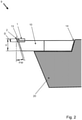
- the width B of the cutting element 1 transversely to the tool axis A is greater than the depth T along the tool axis A and, as can be seen in particular in 2 As can be seen, the thickness D of the cutting element 1 is less than the depth T along the tool axis A.
- the width B transverse to the tool axis A can be between 3.5 mm and 4.5 mm, for example.
- the tool cutting edge 2 is positively formed with a clearance angle FW greater than 0°, which is between 17° and 19°, for example.
- the carrier element 10 is set back behind the clearance angle FW.
- the front end of the carrier element 10 runs parallel and set back to the clearance angle FW.
- the total turning tool thickness Y can be between 2 mm and 4 mm, for example.
- the carrier element 10 consists of a second material which has a lower hardness than the first material (according to the Mohs hardness scale).
- the second material can be a material from the group consisting of tungsten or tungsten alloy, tool steel, boron nitride and ceramics.
- the carrier element 10 has a carrier axis TA, which is offset parallel to the tool axis A by a lateral offset X. This is, for example, between 0.60 cm and 0.80 cm.
- the carrier element 10 has a diamond-shaped basic shape with two blunt 11, 12 and two pointed corners 13, 14 and the carrier axis TA intersects these two pointed corners 13, 14.
- the carrier element 10 has the basic shape of an indexable insert.
- the cutting element 1 is arranged on one of the pointed corners 13 in such a way that the cutting edge 2 protrudes beyond this pointed corner 13 and the rear edge points in the direction of the other pointed corner 14 .
- the attachment of the cutting element 1 to the carrier element 10 is designed in a form-fitting and cohesive manner. A negative recess for a partial section of the cutting element 1 is formed at the pointed corner 13 for the form fit.
- the carrier element 10 is fixed positively and non-positively on the turning tool.
- a negative recess for a partial section of the carrier element 10 is formed on the turning tool 20 for the form fit.
- the turning tool 20 consists of tool steel.
- FIG. 3 In the schematic sketch of 3 one recognizes a lathe 30 with the turning tool 1 and a workpiece 100, namely a lens blank, which is blocked on a workpiece holder 33.
- FIG. The workpiece holder 33 is only indicated with a workpiece spindle 32 driven for receiving and rotating the workpiece 100 about a rotation axis RA.
- a lens axis LA and the axis of rotation RA are aligned coaxially in the present case.
- the cutting element 1 and the workpiece spindle 32 are driven to be movable relative to one another in two or three machine axis directions by an actuating drive 31 (only indicated).
- a method can be carried out with the lathe 30, according to which the concave end face of the workpiece 100 is produced by machining, in that the workpiece 100 is driven in rotation about the axis of rotation RA and the turning tool 9 is rotated from the outside inwards, i.e. towards the axis of rotation RA. is moved.
- the axis of rotation RA and the tool axis A are aligned parallel to one another for machining the end face 101 .
- the turning tool 9 is aligned in such a way that the center point M of the circle lies between the tool axis A and the axis of rotation RA.
Abstract
Schneidelement (1) für eine Drehmaschine (30) der Zerspantechnik, mit einer Werkzeugschneide (2), die aus einem ersten Material besteht, eine Werkzeugachse (A) des Schneidelements (1) in senkrechtem Winkel schneidet, einen Werkzeugradius (R) bezogen auf einen Kreismittelpunkt (M) aufweist, der zwischen 3,0 mm und 7,0 mm beträgt, wobei der Kreismittelpunkt (M) auf der Werkzeugachse (A) liegt, wobei die Werkzeugschneide (2) einen Öffnungswinkel (W) bezogen auf den Kreismittelpunkt (M) aufweist, der maximal 90 Grad beträgt, und wobei das Schneidelement (1) eine Asymmetrie derart aufweist, dass die Werkzeugachse (A) den Öffnungswinkel (W) außermittig schneidet.Drehwerkzeug hiermit.Verfahren zu dem Betrieb des Schneidelements und des Drehwerkzeugs.Verwendung in einem Drehprozess.Cutting element (1) for a lathe (30) for cutting technology, with a tool cutting edge (2), which consists of a first material, intersects a tool axis (A) of the cutting element (1) at a vertical angle, a tool radius (R) based on a has a circle center (M) of between 3.0 mm and 7.0 mm, the circle center (M) lying on the tool axis (A), the tool cutting edge (2) having an opening angle (W) in relation to the circle center (M ) which is a maximum of 90 degrees, and wherein the cutting element (1) has an asymmetry such that the tool axis (A) intersects the opening angle (W) off-centre.Turning tool herewith.Method for the operation of the cutting element and the turning tool.Use in a turning process.
Description
Die Erfindung betrifft ein Schneidelement gemäß dem Oberbegriff von Anspruch 1, ein Drehwerkzeug hiermit nach Anspruch 8, eine Drehmaschine mit einem der beiden nach Anspruch 11, Verfahren nach den Ansprüchen 12 und 13 sowie eine Verwendung nach Anspruch 15, jeweils unter Einsatz des Schneidelements nach Anspruch 1.The invention relates to a cutting element according to the preamble of
Zur Durchführung von Zerspanungsverfahren mit geometrisch bestimmten Schneiden sind Drehverfahren mit Drehmaschinen bekannt. Durch Rotation eines Werkstücks um eine Rotationsachse, wird dessen Oberfläche an einer Werkzeugschneide eines Schneidelements vorbeigeführt und der Span abgehoben. Die weiteren Bewegungen zur Erzeugung des Schnitts, sind meist deutlich langsamer und kürzer und werden meist durch Freiheitsgrade des Drehwerkzeugs umgesetzt.Turning methods with turning machines are known for carrying out machining methods with geometrically defined cutting edges. By rotating a workpiece around an axis of rotation, its surface is guided past a tool cutting edge of a cutting element and the chip is lifted off. The other movements to create the cut are usually much slower and shorter and are usually implemented by the degrees of freedom of the turning tool.
Eine Form des Drehens ist das Quer-Plandrehen. Beim Quer-Plandrehen bewegt sich die Werkzeugschneide quer zur Drehachse. Es wird in der Praxis auch kurz als Plandrehen bezeichnet. Es resultiert im Drehergebnis eine plane Stirnfläche am Werkstück. Eine verwandte Sonderform des Quer-Plandrehens kommt bei der Herstellung optischer Linsenflächen zum Einsatz. Derartiges wird beispielsweise in
Nachteilhaft an den vorbekannten Lösungen ist die langsame Herstellgeschwindigkeit beim Durchführen des Drehverfahrens bedingt durch Werkzeugradien von circa 2 mm und der damit verbunden hohen Anzahl an Umdrehungen zum Überfahren der gesamten Fläche. Die Rotationsgeschwindigkeit lässt sich nämlich nicht nach Belieben erhöhen. Entsprechend ist die Fertigungsstückzahl der Drehmaschine gering. Vor allem bei der Brillenglasfertigung mit hohen Fertigungsvolumen resultiert ein Brillenglaspreis, den es aus betriebswirtschaftlichen Gründen zu reduzieren gilt.A disadvantage of the previously known solutions is the slow production speed when carrying out the turning process, due to tool radii of approximately 2 mm and the associated high number of revolutions for traversing the entire surface. The rotation speed cannot be increased at will. Accordingly, the production volume of the lathe is low. Particularly in the case of the production of spectacle lenses with high production volumes, the price of spectacle lenses has to be reduced for economic reasons.
Mit einer kreisrunden Schneidplatte mit einem Durchmesser von 8 mm, wie sie beispielsweise von
Aufgabe der Erfindung ist es daher, eine technische Lösung bereitzustellen, mit der die Geschwindigkeit der drehenden Bearbeitung von Linsenrohlingen verbessert wird. Die Lösung soll zuverlässig funktionieren, eine hohe Fertigungspräzision haben und preiswert umsetzbar sein. Nach Möglichkeit sollen auch Kunden von Bestandsmaschinen von der Lösung profitieren.It is therefore the object of the invention to provide a technical solution with which the speed of the rotary processing of lens blanks is improved. The solution should work reliably, have high manufacturing precision and be inexpensive to implement. If possible, customers of existing machines should also benefit from the solution.
Hauptmerkmale der Erfindung sind im kennzeichnenden Teil von Anspruch 1, sowie den Ansprüchen 8, 11, 12, 13 und 15 angegeben. Ausgestaltungen sind Gegenstand der Ansprüche 2 bis 7, 9 bis 10 und 14 sowie der Beschreibung.Main features of the invention are set out in the characterizing part of
Die Erfindung betrifft ein Schneidelement für eine Drehmaschine der Zerspantechnik, mit einer Werkzeugschneide, die aus einem ersten Material besteht, die eine (geometrische) Werkzeugachse des Schneidelements in senkrechtem Winkel (geometrisch) schneidet, ausgerichtet ist, einen Werkzeugradius bezogen auf einen Kreismittelpunkt aufweist, wobei der Kreismittelpunkt auf der Werkzeugachse liegt, und einen Öffnungswinkel bezogen auf den Kreismittelpunkt aufweist. Dabei ist vorgesehen, dass der Werkzeugradius zwischen 3,0 mm und 7,0 mm, vorzugsweise zwischen 4,0 mm und 6,0 mm, und besonders bevorzugt zwischen 4,5 mm und 5,5 mm beträgt, dass die Werkzeugschneide einen Öffnungswinkel bezogen auf den Kreismittelpunkt aufweist, der maximal 90 Grad, bevorzugt maximal 70 Grad, weiter bevorzugt maximal 60 Grad, und besonders bevorzugt maximal 55 Grad beträgt, und dass das Schneidelement eine Asymmetrie derart aufweist, dass die Werkzeugachse den Öffnungswinkel außermittig (geometrisch) schneidet.The invention relates to a cutting element for a lathe for cutting technology, with a tool cutting edge, which consists of a first material, which intersects a (geometric) tool axis of the cutting element at a vertical angle (geometrically), is aligned, has a tool radius based on a circle center, wherein the center of the circle lies on the tool axis and has an included angle relative to the center of the circle. It is provided that the tool radius is between 3.0 mm and 7.0 mm, preferably between 4.0 mm and 6.0 mm, and particularly preferably between 4.5 mm and 5.5 mm, that the tool cutting edge has an opening angle relative to the center of the circle, which is a maximum of 90 degrees, preferably a maximum of 70 degrees, more preferably a maximum of 60 degrees, and particularly preferably a maximum of 55 degrees, and that the cutting element has an asymmetry such that the tool axis intersects the opening angle eccentrically (geometrically).
Vorteilhaft hieran ist, dass die Produktivität, durch eine Vergrößerung des Radius des Drehwerkzeuges gegenüber den im Stand der Technik zur Brillenglasherstellung genutzten Radien von bis 2.0 mm, gesteigert werden kann. Dies gelingt insbesondere durch die Verringerung der notwendigen Umdrehungen, um die Oberfläche zu bearbeiten. Dabei wird mittels dem Werkzeugradius von über 3,0 mm die Spiralgangbreite erhöht, ohne die gedrehte Oberflächenstruktur {Spitzenhöhe) stark zu verändern, um die späteren Gläser mit den Standardparametern polieren zu können. Dabei werden zerstörende Kontakte der Werkzeugschneide mit Oberflächenbereichen, die bei der Brillenglasherstellung nicht abgetragen werden sollen, durch die Asymmetrie vermieden, obwohl der vergleichsweise große Radius der Werkzeugschneide genutzt wird. So steigt bei einem exemplarischen Vergleich einer symmetrischen Werkzeugschneide mit 2 mm Radius und einer asymmetrischen Werkzeugschneide mit 5 mm Radius die Spiralgangbreite bei der Bearbeitung eines Linsenrohlings von 0,033 mm auf 0,053 mm, die Anzahl der Umdrehungen für einen typischen Durchmesser des Linsenrohlings von 65 mm sinkt von circa 2.000 auf 1.250 Umdrehungen, wobei jeweils eine gefertigte Spitzenhöhe zwischen den Spiralgängen auf 0,07 µm begrenzt ist. Dieser 5 mm erscheint in der Brillenglasfertigung als idealer Werkzeugradius, mit dem noch eine Vielzahl an Gläsern zügig. bearbeitet werden können. Die Spitzenhöhen lassen sich auch bei Einsatz des erfindungsgemäßen Schneidelements mit zumindest nahezu gleichem Aufwand polieren. Die Prozesszeit des Drehens sinkt entsprechend der notwendigen Umdrehungen bei gleicher Rotationsgeschwindigkeit um circa 37,5 %. Das erfindungsgemäße Schneidelement lässt sich auch ohne mechanischen oder steuerungstechnischen Umbau in vielen Bestandsmaschinen nutzen, sodass eine kundenfreundliche Nachrüstbarkeit der Lösung bereitsteht.The advantage of this is that the productivity can be increased by increasing the radius of the turning tool compared to the radii of up to 2.0 mm used in the prior art for producing spectacle lenses. This is achieved in particular by reducing the number of revolutions required to process the surface. The spiral path width is increased by means of the tool radius of over 3.0 mm without significantly changing the turned surface structure (peak height) in order to be able to polish the later glasses with the standard parameters. The asymmetry avoids destructive contacts between the cutting edge of the tool and surface areas that are not intended to be removed during the manufacture of spectacle lenses, although the comparatively large radius of the cutting edge of the tool is used. In an exemplary comparison of a symmetrical tool cutting edge with a 2 mm radius and an asymmetrical tool cutting edge with a 5 mm radius, the spiral pitch width increases from 0.033 mm to 0.053 mm when processing a lens blank, while the number of revolutions for a typical lens blank diameter of 65 mm decreases Approximately 2,000 to 1,250 revolutions, with a manufactured peak height between the spiral turns being limited to 0.07 µm. This 5 mm appears to be the ideal tool radius in eyeglass lens production, with which a large number of lenses can be quickly manufactured. can be edited. The peak heights can also be polished with at least almost the same effort when using the cutting element according to the invention. The turning process time is reduced by around 37.5% in accordance with the required number of revolutions at the same rotational speed. The cutting element according to the invention can also be used without mechanical or control engineering conversion in many Use existing machines so that the solution can be retrofitted in a customer-friendly manner.
In einer Ausgestaltungsvariante ist das erste Material ein synthetischer Diamantwerkstoff, insbesondere aus der Gruppe Polykristalliner Diamant (PKD), Chemical Vapor Deposition (CVD), synthetischer monokristalliner Diamant (MKD) und aggregierte Diamant-Nanostäbchen (ADNR), oder polykristallines kubisches Bornitrid (CBN), oder ein Naturdiamant (ND). Diese harten Werkstoffe eignen sich besonders gut für die Bearbeitung von Glas und hochfesten Kunststoffen, wie sie bei der Brillenglasfertigung zu bearbeiten sind.In one embodiment variant, the first material is a synthetic diamond material, in particular from the group of polycrystalline diamond (PCD), chemical vapor deposition (CVD), synthetic monocrystalline diamond (MKD) and aggregated diamond nanorods (ADNR), or polycrystalline cubic boron nitride (CBN) , or a natural diamond (ND). These hard materials are particularly suitable for processing glass and high-strength plastics, such as those to be processed in the manufacture of spectacle lenses.
Optional ist die Asymmetrie derart ausgebildet, dass auf einer ersten Seite der Werkzeugachse ein längerer Abschnitt der Werkzeugschneide angeordnet ist als auf der gegenüberliegenden zweiten Seite der Werkzeugachse. Hierdurch werden in Abhängigkeit der Vorschubbewegung der Werkzeugschneide unterschiedliche Bearbeitungen ermöglicht. Dies ist insbesondere bei gekrümmten Bearbeitungsflächen hilfreich, um Kollisionen des Schneidelements abseits des Spiralgangs zu vermeiden und so ungewollt Material abzutragen. Außerdem ist das Schneidelement preiswerter, als wenn es sich auf beiden Seiten gleich weit von der Werkzeugachse wegerstrecken würde. Bei der Bearbeitung von schrägen Flächen wird der ins Tal weisende Abschnitt des Schneidelements weit weniger oder gar nicht gebraucht als der zum Berg weisende Abschnitt und kann deshalb entfallen.Optionally, the asymmetry is designed in such a way that a longer section of the tool cutting edge is arranged on a first side of the tool axis than on the opposite, second side of the tool axis. This enables different machining depending on the feed movement of the tool cutting edge. This is particularly helpful with curved machining surfaces in order to avoid collisions of the cutting element off the spiral path and thus unintentionally remove material. In addition, the cutting element is less expensive than if it were to extend equally far from the tool axis on both sides. When working on sloping surfaces, the section of the cutting element pointing down the valley is used far less or not at all than the section pointing up the hill and can therefore be omitted.
Weiterhin ist eine Ausgestaltung zu bevorzugen, gemäß der die Asymmetrie derart ausgebildet ist, dass mit dem Bereich der Werkzeugschneide, die quer zur Werkzeugachse ausgerichtet ist, eher gerade Planflächen bearbeitet werden können, und sich der Mittelpfad des Spiralgangs bei zunehmendem Prismenwinkel auf der Bearbeitungsfläche in Richtung des schrägeren Bereichs verschiebt.Furthermore, a configuration is to be preferred according to which the asymmetry is formed in such a way that straight flat surfaces can be machined with the area of the tool cutting edge, which is aligned transversely to the tool axis, and the central path of the spiral path with increasing prism angle on the machining surface in the direction of the sloping area shifts.
In einer speziellen Ausführungsform ist die Asymmetrie derart ausgebildet, dass das Schneidelement auf einer ersten Seite der Werkzeugachse spitzer zuläuft als auf der gegenüberliegenden zweiten Seite der Werkzeugachse. Hierdurch lässt sich die Menge des vergleichsweise teuren ersten Materials reduzieren, indem in typischerweise weniger beanspruchten Bereich des Schneidelements auch weniger Material hinter der Werkzeugschneide angeordnet ist.In a special embodiment, the asymmetry is designed in such a way that the cutting element tapers more pointedly on a first side of the tool axis than on the opposite, second side of the tool axis. As a result, the quantity of the comparatively expensive first material can be reduced, in that less material is also arranged behind the cutting edge of the tool in the typically less stressed area of the cutting element.
Weiterhin kann die Asymmetrie derart ausgebildet sein, dass sich das Schneidelement, im Besonderen die Werkzeugschneide, auf einer ersten Seite der Werkzeugachse weiter von der Werkzeugachse weg erstreckt als auf der gegenüberliegenden zweiten Seite der Werkzeugachse, vorzugsweise auf der ersten Seite wenigstens doppelt so weit wegerstreckt wie auf der zweiten Seite, weiter bevorzugt auf der ersten Seite wenigstens zweieinhalbmal so weit wegerstreckt wie auf der zweiten Seite, und besonders bevorzugt auf der ersten Seite wenigstens dreimal so weit wegerstreckt wie auf der zweiten Seite. Maximal sollte sich das Schneidelement auf der ersten Seite der Werkzeugachse um das Fünffache von der Werkzeugachse wegerstrecken als auf der gegenüberliegenden zweiten Seite der Werkzeugachse.Furthermore, the asymmetry can be designed in such a way that the cutting element, in particular the tool cutting edge, extends further away from the tool axis on a first side of the tool axis than on the opposite second side of the tool axis, preferably at least twice as far on the first side as on the second side, more preferably extending on the first side at least two and a half times as far as on the second side, and most preferably extending on the first side at least three times as far as on the second side. At most, the cutting element should extend away from the tool axis five times on the first side of the tool axis than on the opposite second side of the tool axis.
Optional kann sich an den Enden der Werkzeugschneide jeweils eine Seitenfläche anschließen, die innerhalb des Werkzeugradius R angeordnet ist. Die Seitenflächen bilden also den seitlichen Abschluss der Werkzeugschneide und begrenzen gewissermaßen eine Trägermatrix der Werkzeugschneide. Dabei können die Seitenflächen exakt oder zumindest im Wesentlichen parallel zueinander und/oder der Werkzeugachse ausgerichtet sein oder beginnend an den zwei Enden der Werkzeugschneide aufeinander zulaufen.Optionally, a side surface, which is arranged within the tool radius R, can adjoin the ends of the tool cutting edge. The side surfaces thus form the lateral termination of the cutting edge of the tool and, to a certain extent, delimit a carrier matrix of the cutting edge of the tool. The side surfaces can be aligned exactly or at least essentially parallel to one another and/or the tool axis or run towards one another starting at the two ends of the tool cutting edge.
Hinsichtlich der Größenverhältnisse bietet sich eine Ausgestaltung an, wonach die Breite des Schneidelements quer zur Werkzeugachse größer ist als die Tiefe entlang der Werkzeugachse. Hierdurch lässt sich die Menge des vergleichsweise teuren ersten Materials reduzieren. Dabei sollte die Breite des Schneidelements quer zur Werkzeugachse zwischen 3,0 mm und 6,0 mm, bevorzugt zwischen 3,5 mm und 5,0 mm und besonders bevorzugt zwischen 3,5 mm und 4,5 mm betragen.With regard to the proportions, an embodiment is possible according to which the width of the cutting element transversely to the tool axis is greater than the depth along the tool axis. This allows the amount of the comparatively expensive first material to be reduced. The width of the cutting element transverse to the tool axis should be between 3.0 mm and 6.0 mm, preferably between 3.5 mm and 5.0 mm and particularly preferably between 3.5 mm and 4.5 mm.
Schließlich sollte das Schneidelement eine Hinterkante aufweisen, die exakt oder zumindest im Wesentlichen quer zur Werkzeugachse ausgerichtet ist.Finally, the cutting element should have a trailing edge that is aligned exactly or at least substantially transversely to the tool axis.
Im Speziellen kann das Schneidelement die Grundform eines Plättchens aufweisen, dessen Plättchendicke geringer ist als die Breite quer zur Werkzeugachse und geringer ist als die Tiefe entlang der Werkzeugachse.In particular, the cutting element can have the basic shape of a plate, the plate thickness of which is less than the width transverse to the tool axis and less than the depth along the tool axis.
Für eine effiziente Bearbeitung von Glas bietet sich eine Auslegung an, wonach die Werkzeugschneide positiv mit einem Freiwinkel größer 0° ausgebildet ist, wobei der Freiwinkel vorzugsweise zwischen 10° und 25°, weiter bevorzugt zwischen 14° und 21°, und besonders bevorzugt zwischen 17° und 19° beträgt.For efficient processing of glass, a design is recommended according to which the cutting edge of the tool is positively designed with a clearance angle greater than 0°, with the clearance angle preferably being between 10° and 25°, more preferably between 14° and 21°, and particularly preferably between 17 ° and 19°.
Die Erfindung betrifft außerdem ein Drehwerkzeug mit einem Schneidelement wie es vor- und nachstehend beschrieben ist, das an einem Trägerelement aus einem zweiten Material festgelegt ist, wobei das erste Material eine höhere Härte aufweist als das zweite Material, wobei das Trägerelement eine Trägerachse aufweist, die parallel und/oder koaxial zur Werkzeugachse ausgerichtet ist.The invention also relates to a turning tool with a cutting element as described above and below, which is fixed to a carrier element made of a second material, the first material having a higher hardness than the second material, the carrier element having a carrier axis which is aligned parallel and/or coaxially to the tool axis.
Damit gelingt eine materialtechnische Funktionstrennung zwischen den Aufgaben Positionieren und stützen der Werkzeugschneide und dem Schneiden durch die Werkzeugscheide. Mithin kann ein teures erstes Material und ein im Vergleich günstigeres zweites Material eingesetzt werden, wodurch die Drehwerkzeugkosten gering sind. Außerdem kann die Werkzeugschneide aufgrund der hohen Härte vorrangig auf das Schneiden ausgelegt werden, wohingegen das Trägerelement zäher und weniger spröde ist, um beispielsweise bei einem Einklemmen oder Festschrauben an einem Drehmeißel nicht zu brechen. Des Weiteren lassen sich die Wärmeableitung und geringfügige Dämpfungen mit dem Trägerelement aus weniger hartem Material erzielen. Die Materialeigenschaft Härte soll vorliegend gemäß der Härteskala nach Mohs verstanden werden.This achieves a material-technical functional separation between the tasks of positioning and supporting the tool cutting edge and cutting with the tool sheath. Consequently, an expensive first material and a comparatively cheaper second material can be used, as a result of which the turning tool costs are low. In addition, due to the high degree of hardness, the cutting edge of the tool can primarily be designed for cutting, whereas the carrier element is tougher and less brittle so that it does not break, for example, if it is jammed or screwed to a lathe tool. Furthermore, the heat dissipation and minor damping can be achieved with the supporting element made of less hard material. The material property of hardness is to be understood here according to the Mohs hardness scale.
Bei dem zweiten Material handelt es sich vorzugsweise um einen Werkstoff aus der Gruppe Wolfram oder Wolframlegierung, Werkzeugstahl, Bornitrit und Keramik. Wolframwerkstoffe eignen sich besonders gut zur Ausbildung hochfester dauerhafter Verbindungen mit Diamantwerkstoffen. Werkzeugstahl ist vergleichsweise preiswert. Bornitrit hat eine hohe Härte, wodurch das Schneidelement besonders präzise und ungedämpft gelagert ist. Keramiken sind ebenfalls sehr hart und meist preiswerter als Wolfram und Bornitrit.The second material is preferably a material from the group consisting of tungsten or a tungsten alloy, tool steel, boron nitrite and ceramics. Tungsten materials are particularly suitable for forming high-strength, permanent connections with diamond materials. Tool steel is comparatively inexpensive. Boron nitrite has a high level of hardness, which means that the cutting element is mounted particularly precisely and undamped. Ceramics are also very hard and usually cheaper than tungsten and boron nitrite.
Gemäß einer speziellen Ausführung ist die Befestigung des Schneidelements am Trägerelement kraftschlüssig, formschlüssig und/oder stoffschlüssig ausgebildet. Kraftschlüssige Verbindungen sind sehr stabil, können jedoch Verformungen verursachen und in Abhängigkeit von der Härte des ersten Materials teilweise problematisch sein, weil das Schneidelement aufgrund der Sprödigkeit brechen kann. Bei derartigen Problemen wird die kraftschlüssige Verbindung daher bevorzugt in Ergänzung zu Formschluss und/oder Stoffschluss eingesetzt. Ein Formschluss ermöglicht eine hochpräzise Befestigung und einfache Positionierung bei der Herstellung. In den meisten Anwendungsfällen reicht der Formschluss jedoch in Alleinstellung nicht für die Befestigung, weswegen er vorzugsweise durch einen Kraftschluss oder einen Stoffschluss ergänzt wird. Ein Stoffschluss ermöglicht eine stabile dauerhafte Verbindung mit guter Wärmedurchleitung bereits in Alleinstellung. Dennoch kann er optional durch einen Formschluss oder einen Kraftschluss ergänzt werden. Hierdurch lässt sich die Stabilität und Dauerfestigkeit erhöhen und ggf. auch eine Verliersicherung für das ggf. sehr teure erste Material ausbilden.According to a special embodiment, the attachment of the cutting element to the carrier element is designed in a force-fitting, form-fitting and/or material-fitting manner. Force-locked connections are very stable, but can cause deformation and, depending on the hardness of the first material, can sometimes be problematic because the cutting element can break due to the brittleness. In the case of such problems, the non-positive connection is therefore preferably used in addition to the positive connection and/or material connection. A form fit enables high-precision attachment and easy positioning during manufacture. In most applications, however, the form fit alone is not sufficient for attachment, which is why it is preferably supplemented by a force fit or a bonded fit. A material connection enables a stable, permanent connection with good heat conduction, even on its own. Nevertheless, it can optionally be supplemented by a form fit or a force fit. As a result, the stability and fatigue strength can be increased and, if necessary, a loss prevention device for the first material, which can be very expensive, can be formed.
Im Besonderen kann das Trägerelement eine rautenförmige Grundform mit zwei stumpfen und zwei spitzen Ecken aufweisen, wobei das Schneidelement an oder auf einer der spitzen Ecken angeordnet ist. Hierdurch lässt sich das Drehwerkzeug in der Flucht hinter der Werkzeugschneide in einer Drehmaschine festlegen, sodass die Umgebung um die Werkzeugschneide möglichst frei von physischen Bauteilen ist, die mit dem Werkstück kollidieren könnten. Außerdem ist die Rautenform gängige Negativform von Drehmeißeln zur Aufnahme von herkömmlichen Schneidplatten, sodass sich das erfindungsgemäße Drehwerkzeug in Bestandsmeißel und damit auch Bestandsdrehmaschinen einsetzen lässt. Entsprechend bietet sich eine Auslegung derart an, dass das Trägerelement die Grundform einer Wendeschneidplatte aufweist.In particular, the carrier element can have a diamond-shaped basic shape with two blunt and two pointed corners, with the cutting element being arranged at or on one of the pointed corners. This allows the turning tool to be set in alignment behind the tool cutting edge in a lathe, so that the environment around the Tool cutting edge is as free as possible of physical components that could collide with the workpiece. In addition, the diamond shape is a common negative shape of turning tools for holding conventional cutting inserts, so that the turning tool according to the invention can be used in existing tools and thus also in existing lathes. Accordingly, a design such that the carrier element has the basic shape of an indexable insert is appropriate.
In der Variante des Drehwerkzeugs, bei der die Trägerachse und die Werkzeugachse parallel zueinander ausgerichtet sind, kann optional ein Seitenversatz zwischen Trägerachse und der Werkzeugachse bestehen, der zwischen 0,40 cm und 1,10 cm, bevorzugt zwischen 0,55 cm und 0,90 cm und besonders bevorzugt zwischen 0,60 cm und 0,80 cm beträgt. Durch den Seitenversatz verschiebt sich die Werkzeugschneide vor dem Trägerelement, wobei dies bevorzugt in der Richtung erfolgt, die bewirkt, dass die Werkzeugschneide die Trägerachse (geometrisch) weniger schräg schneidet. Entsprechend liegt dann die Mittelachse des Spiralgangs bei einer Bearbeitung von gekrümmten Stirnflächen zentraler vor der Trägerachse. Ein geringfügiger Versatz kann aber durchaus gewünscht sein, denn die Mittellinie des Spiralgangs verlagert sich aufgrund der prismatischen Schräge der Bearbeitungsfläche gegenüber einer reinen Planfläche.In the variant of the turning tool in which the carrier axis and the tool axis are aligned parallel to one another, there can optionally be a lateral offset between the carrier axis and the tool axis of between 0.40 cm and 1.10 cm, preferably between 0.55 cm and 0. 90 cm and more preferably between 0.60 cm and 0.80 cm. Due to the lateral offset, the tool cutting edge is displaced in front of the carrier element, this preferably taking place in the direction which causes the tool cutting edge to (geometrically) intersect the carrier axis less obliquely. Correspondingly, the central axis of the spiral thread then lies more centrally in front of the carrier axis when curved end faces are being machined. However, a slight offset can definitely be desired, because the center line of the spiral path shifts due to the prismatic slope of the working surface compared to a purely flat surface.
Vorzugsweise weist das Trägerelement ein Befestigungsloch zur Festlegung auf einem Drehmeißel auf. Damit lässt sich eine schnelle Montage und ein schneller Austausch des Drehwerkzeugs, beispielsweise mittels einer Befestigungsschraube, erzielen. Das Drehwerkzeug kann auch einen Drehmeißel aufweisen. An diesem ist das Trägerelement mechanisch lösbar festgelegt, beispielsweise mittels einer Befestigungsschraube. Der Drehmeißel ist also ein vom Trägerelement separates Bauteil. Er hat vorzugsweise einen Montageschaft, zur Festlegung in einer Werkzeugaufnahme einer Drehmaschine. Dabei besteht der Drehmeißel bevorzugt aus Werkzeugstahl.Preferably, the support member has a mounting hole for attachment to a lathe tool. This makes it possible to quickly assemble and replace the turning tool, for example by means of a fastening screw. The turning tool can also have a turning tool. The carrier element is mechanically detachably fixed to this, for example by means of a fastening screw. The lathe tool is therefore a separate component from the carrier element. It preferably has a mounting shank for fixing in a tool holder of a lathe. The lathe tool is preferably made of tool steel.
Des Weiteren betrifft die Erfindung eine Drehmaschine mit einem Schneidelement, wie es vor- und nachstehend beschrieben ist, oder einem Drehwerkzeug, wie es vor- und nachstehend beschrieben ist, und mit einer Werkstückspindel zur Aufnahme und Rotation eines Werkstücks um eine Rotationsachse, wobei die Rotationsachse und die Werkzeugachse zur Bearbeitung einer Stirnfläche des Werkstücks exakt oder zumindest im Wesentlichen parallel zueinander ausgerichtet sind, und wobei das Schneidelement und die Werkstückspindel relativ zueinander in zwei oder drei Maschinenachsrichtungen bewegbar mit einem Stellantrieb angetrieben sind.The invention also relates to a lathe with a cutting element, as described above and below, or a turning tool, as described above and below, and with a workpiece spindle for receiving and rotating a workpiece about an axis of rotation, the axis of rotation and the tool axes for machining an end face of the workpiece are aligned exactly or at least substantially parallel to one another, and wherein the cutting element and the workpiece spindle are driven with an actuator so that they can be moved relative to one another in two or three machine axis directions.
Mit dieser Drehmaschine lassen sich nunmehr aufgrund der asymmetrischen Werkzeugschneide mit großem Radius gekrümmte Stirnflächen besonders schnell herstellen.With this lathe, curved end faces can now be produced particularly quickly due to the asymmetrical tool cutting edge with a large radius.
Im Besonderen lässt sich beispielsweise die Stirnseite eines Linsenrohlings von außen nach innen zur Rotationsachse mit der Werkzeugschneide abfahren. Es resultiert durch die Rotation des Werkstücks ein spiralförmiger Arbeitspfad, den die Werkzeugschneide auf dem Werkstück zurücklegt. Die Querbewegung der Werkzeugschneide wird zusätzlich durch eine Längsbewegung parallel oder zumindest im Wesentlichen gleichgerichtet zur Rotationsachse überlagert. Vorzugsweise weist der Stellantrieb einen Servomotor wie ein Fast-Tool, eine Tauchspule oder einen Piezo-Aktuator auf. Außerdem bietet es sich an einen Stellantrieb mit einem Kreuztisch einzusetzen, um die Maschinenachsen auszubilden. Vorzugsweise ist eine der Maschinenachsrichtungen zumindest im Wesentlichen oder exakt parallel zur Trägerachse ausgerichtet.In particular, for example, the end face of a lens blank can be traversed from the outside in towards the axis of rotation with the cutting edge of the tool. The rotation of the workpiece results in a spiral working path that the cutting edge of the tool covers on the workpiece. The transverse movement of the cutting edge is additionally superimposed by a longitudinal movement parallel or at least essentially in the same direction as the axis of rotation. The actuator preferably has a servo motor such as a fast tool, a plunger coil or a piezo actuator. It is also advisable to use an actuator with a cross table to form the machine axes. One of the machine axis directions is preferably aligned at least essentially or exactly parallel to the carrier axis.
Fernerhin betrifft die Erfindung ein Verfahren zum Betrieb einer Drehmaschine mit einem ersten Drehwerkzeug wie es vor- und nachstehend beschrieben ist und einem zweiten Drehwerkzeug, dessen Werkzeugradius kleiner ist als der Werkzeugradius des ersten Drehwerkzeugs, wobei mittels einer Entscheidungslogik entschieden wird, ob die Bearbeitung einer vordefinierten Bearbeitungsfläche eines Werkstücks mit dem ersten Drehwerkzeug oder dem zweiten Drehwerkzeug durchgeführt wird, wobei die Entscheidungslogik eine maximal herzustellende Flächenkrümmung bestimmt und mit einem definierten Grenzwert abgleicht und/oder einen maximal herzustellenden Prismenwinkel bestimmt und mit einem definierten Grenzwert abgleicht, und wobei bei Übersteigen eines der Grenzwerte anstatt des ersten Drehwerkzeugs das zweite Drehwerkzeug für die Bearbeitung eingesetzt wird.Furthermore, the invention relates to a method for operating a turning machine with a first turning tool as described above and below and a second turning tool whose tool radius is smaller than the tool radius of the first turning tool, with a decision logic being used to decide whether the machining of a predefined Machining surface of a workpiece is carried out with the first turning tool or the second turning tool, with the decision logic determining a maximum surface curvature to be produced and comparing it with a defined limit value and/or determining a maximum prism angle to be produced and comparing it with a defined limit value, and with one of the limit values being exceeded instead of the first turning tool, the second turning tool is used for machining.
Mit dem Verfahren wird zum Beispiel bei der Brillenglasfertigung mit ständig wechselnden Oberflächengeometrien und Linsenrohlingskrümmungen sichergestellt, dass wann immer möglich, das aufgrund des größeren Werkzeugradius schneller arbeitende erste Drehwerkzeug eingesetzt wird. Wann immer jedoch, aufgrund eines zu steilen Prismenwinkels oder zu engem Radius der breite Werkzeugradius die Zieloberfläche nicht herstellen kann, wird auf das zweite Drehwerkzeug mit kleinerem Werkzeugradius zurückgegriffen. Plakativ ausgedrückt könnte man sagen, dass man das Drehwerkzeug mit kleinerem Werkzeugradius hernimmt, um besser in die Ecken zu kommen, wenn solche Ecken vorhanden sind.The process ensures, for example in the production of spectacle lenses with constantly changing surface geometries and lens blank curvatures, that whenever possible the first turning tool, which works faster due to the larger tool radius, is used. However, whenever the wide tool radius cannot produce the target surface due to a prism angle that is too steep or a radius that is too narrow, the second turning tool with a smaller tool radius is used. To put it bluntly, one could say that the turning tool is used with a smaller tool radius in order to get better into the corners when such corners are present.
Das Verfahren erfolgt optional so, dass die Entscheidungslogik automatisiert mit einer Steuereinheit erfolgt und das erste oder zweite Drehwerkzeug automatisiert angesteuert und eingesetzt wird. Damit ist ein vollautomatisierter Verfahrensablauf in den meist ohnehin automatisierten CNC-Fertigungsablauf bspw. einer Brillenglasfertigung ermöglicht.The method optionally takes place in such a way that the decision logic takes place automatically with a control unit and the first or second turning tool is controlled and used automatically. This enables a fully automated process sequence in the CNC production sequence, which is usually automated anyway, for example in the production of spectacle lenses.
Bei einem weiteren erfindungsgemäßen Verfahren zum Betrieb einer Drehmaschine mit einem ersten Drehwerkzeug wie es vor- und nachstehend beschrieben ist, ist vorgesehen, dass am Werkstück eine konkave Stirnseite durch Zerspanung hergestellt wird, indem das Werkstück rotierend um eine Rotationsachse angetrieben ist und das Drehwerkzeug von außen nach innen auf die Rotationsachse zu bewegt wird, wobei die Rotationsachse und die Werkzeugachse zur Bearbeitung der Stirnfläche exakt oder zumindest im Wesentlichen parallel zueinander ausgerichtet sind, und wobei das Drehwerkzeug so ausgerichtet ist, dass der Kreismittelpunkt zwischen der Werkzeugachse und der Rotationsachse liegt.In a further method according to the invention for operating a turning machine with a first turning tool as described above and below, it is provided that on workpiece, a concave end face is produced by machining, in that the workpiece is driven to rotate about an axis of rotation and the turning tool is moved from the outside in towards the axis of rotation, the axis of rotation and the tool axis for machining the end face being aligned exactly or at least essentially parallel to one another and wherein the turning tool is oriented such that the center of the circle lies between the tool axis and the axis of rotation.
Entsprechend ist basierend auf der einseitig abzufahrenden Hälfte des konkaven Werkstücks eine passende Ausrichtung der asymmetrischen Werkzeugschneide realisiert.Correspondingly, based on the half of the concave workpiece to be machined on one side, a suitable alignment of the asymmetrical tool cutting edge is realized.
Grundsätzlich kann dabei eine Linsenachse des Werkstücks koaxial zur Rotationsachse ausgerichtet sein. Alternativ ist jedoch auch möglich, dass das Werkstück prismatisch an einem Werkstückhalter gehalten ist, vorzugsweise aufgeblockt ist, sodass eine Linsenachse des Werkstücks einen Winkel größer als 0°, vorzugsweise zwischen 0,20° und 2,00°, weiter bevorzugt zwischen 0,50° und 1,80° und besonders bevorzugt zwischen 0,80° und 1,50° zur Rotationsachse aufweist. Durch diesen Winkel können ungewollte Kollisionen des Werkstücks mit der Werkzeugschneide vermieden werden, sodass zusätzlich zu den ohnehin mit dem ersten Drehwerkzeug bearbeitbaren Flächen weitere Flächengeometrien schnell herstellbar sind. Damit reduziert sich beispielsweise die Anzahl der Linsenrohlinge, die mit einem Drehwerkzeug mit kleinerem Werkzeugradius bearbeitet werden müssen.Basically, a lens axis of the workpiece can be aligned coaxially to the axis of rotation. Alternatively, however, it is also possible for the workpiece to be held prismatically on a workpiece holder, preferably blocked, so that a lens axis of the workpiece has an angle greater than 0°, preferably between 0.20° and 2.00°, more preferably between 0.50 ° and 1.80 ° and particularly preferably between 0.80 ° and 1.50 ° to the axis of rotation. This angle makes it possible to avoid unwanted collisions of the workpiece with the cutting edge of the tool, so that additional surface geometries can be quickly produced in addition to the surfaces that can be machined with the first turning tool anyway. This reduces, for example, the number of lens blanks that have to be machined with a turning tool with a smaller tool radius.
Fernerhin betrifft die Erfindung eine Verwendung eines Schneidelements, wie es vor- und nachstehend beschrieben ist, oder eines Drehwerkzeugs, wie es vor- und nachstehend beschrieben ist, bei der Herstellung gekrümmter Oberflächen durch Zerspanung in einem Drehprozess. Auch bei dieser Verwendung wird eine hohe Effizienz durch die asymmetrische Werkzeugschneide mit großem Radius erzielt.Furthermore, the invention relates to the use of a cutting element, as described above and below, or a turning tool, as described above and below, in the production of curved surfaces by machining in a turning process. With this use, too, a high level of efficiency is achieved thanks to the asymmetrical tool cutting edge with a large radius.
Von besonderem Vorteil sind die Verfahren und die Verwendung, wenn das Werkstück ein Linsenrohling aus einem transparenten oder transluzenten Werkstoff ist.The methods and the use are of particular advantage when the workpiece is a lens blank made of a transparent or translucent material.
Von besonderem Vorteil sind die Verfahren und die Verwendung auch, wenn das Werkstück zu einer optischen Linse, insbesondere einem Brillenglas, und ganz besonders zu einem Rezeptglas mit einer asphärischen Fläche oder einer Freiformfläche bearbeitet wird.The methods and the use are also of particular advantage when the workpiece is machined to form an optical lens, in particular a spectacle lens, and very particularly to form a prescription lens with an aspherical surface or a free-form surface.
Weitere Merkmale, Einzelheiten und Vorteile der Erfindung ergeben sich aus dem Wortlaut der Ansprüche sowie aus der folgenden Beschreibung von Ausführungsbeispielen anhand der Zeichnungen. Es zeigen:
- Fig. 1
- eine schematische Draufsicht auf ein Drehwerkzeug mit Schneidelement;
- Fig. 2
- eine Seitenansicht des Drehwerkzeugs nach
Fig. 1 aufweisend einen zusätzlichen Drehmeißel; und - Fig. 3
- eine Schemaskizze einer Drehmaschine mit dem Drehwerkzeug nach
Fig. 1 sowie einem Werkstück.
- 1
- a schematic plan view of a rotary tool with a cutting element;
- 2
- a side view of the
turning tool 1 having an additional lathe tool; and - 3
- a schematic sketch of a lathe with the
lathe tool 1 and a workpiece.
Ein Kreismittelpunkt M bildet des Ausgangspunkt des Werkzeugradius R. Der Kreismittelpunkt M liegt auf einer Werkzeugachse A, die die Werkzeugschneide 2 in senkrechtem Winkel schneidet. Die Werkzeugschneide 2 weist einen Öffnungswinkel W auf, der am Kreismittelpunkt M zu bestimmen ist, und der vorliegend weniger als 55 beträgt. Mit anderen Worten ist die Werkzeugschneide durch einen Kreisbahnausschnitt definiert, der hier kleiner als 55° ist. Wie man erkennt, ist das Schneidelement asymmetrisch ausgestaltet. Dieser Asymmetrie wohnen folgende Eigenschaften inne:
- Die Werkzeugachse A schneidet den Öffnungswinkel W außermittig;
- Auf einer ersten Seite S1 der Werkzeugachse A ist ein längerer Abschnitt A1 der
Werkzeugschneide 2 angeordnet als auf der gegenüberliegenden zweiten Seite S2 der Werkzeugachse A; Das Schneidelement 1 läuft auf der ersten Seite S1 der Werkzeugachse A spitzer zu als auf der zweiten Seite S2;Das Schneidelement 1 erstreckt sich auf der ersten Seite S1 weiter von der Werkzeugachse A weg als auf der zweiten Seite S2, hier insbesondere um mehr als dreimal so weit.
- The tool axis A intersects the opening angle W eccentrically;
- A longer section A1 of the
tool cutting edge 2 is arranged on a first side S1 of the tool axis A than on the opposite second side S2 of the tool axis A; - The cutting
element 1 tapers on the first side S1 of the tool axis A than on the second side S2; - The cutting
element 1 extends further away from the tool axis A on the first side S1 than on the second side S2, here in particular more than three times as far.
An den Enden der Werkzeugschneide 2 schließt sich jeweils eine Seitenfläche 3, 4 an die Werkzeugschneide 2 an, die innerhalb des Werkzeugradius R angeordnet ist. Die Seitenflächen 3, 4 sind exakt parallel zueinander und auch zu der Werkzeugachse A ausgerichtet. Der Werkzeugschneide 2 gegenüberliegend bildet eine gerade Hinterkante 5 einen Abschluss des Schneidelements 1. Die Hinterkante 5 ist exakt quer, also senkrecht zur Werkzeugachse A ausgerichtet.At the ends of the
Hinsichtlich der relativen Dimensionen wird deutlich, dass die Breite B des Schneidelements 1 quer zur Werkzeugachse A größer ist als die Tiefe T entlang der Werkzeugachse A und wie man vor allem in
Wie man vor allem in
Das Trägerelement 10 besteht aus einem zweiten Material, das eine geringere Härte aufweist als das erste Material (gemäß Härteskala nach Mohs). Das zweite Material kann ein Werkstoff aus der Gruppe Wolfram oder Wolframlegierung, Werkzeugstahl, Bornitrit und Keramik sein.The
Das Trägerelement 10 hat eine Trägerachse TA, die parallel um einen Seitenversatz X versetzt zur Werkzeugachse A ausgerichtet ist. Dieser beträgt beispielsweise zwischen 0,60 cm und 0,80 cm. Dabei hat das Trägerelement 10 eine rautenförmige Grundform mit zwei stumpfen 11, 12 und zwei spitzen Ecken 13, 14 und die Trägerachse TA schneidet diese zwei spitzen Ecken 13, 14. Hierdurch hat das Trägerelement 10 die Grundform einer Wendeschneidplatte. Dabei ist das Schneidelement 1 derart auf einer der spitzen Ecken 13 angeordnet, dass die Werkzeugschneide 2 über diese spitze Ecke 13 hinausragt und die Hinterkante in Richtung der anderen spitzen Ecke 14 weist. Die Befestigung des Schneidelements 1 am Trägerelement 10 ist form- und stoffschlüssig ausgebildet. Für den Formschluss ist eine Negativausnehmung für einen Teilausschnitt des Schneidelements 1 an der spitzen ecke 13 ausgebildet.The
Mittels einer Schraube, die durch das in
In der Schemaskizze der
Das Schneidelement 1 und die Werkstückspindel 32 sind mit einem nur angedeuteten Stellantrieb 31 relativ zueinander in zwei oder drei Maschinenachsrichtungen bewegbar angetrieben.The cutting
In
Mit der Drehmaschine 30 lässt sich ein Verfahren durchführen, gemäß dem die konkave Stirnseite des Werkstücks 100 durch Zerspanung hergestellt wird, indem das Werkstück 100 rotierend um die Rotationsachse RA angetrieben ist und das Drehwerkzeug 9 von außen nach innen, also auf die Rotationsachse RA zu, bewegt wird. Dabei sind die Rotationsachse RA und die Werkzeugachse A zur Bearbeitung der Stirnfläche 101 parallel zueinander ausgerichtet sind. Das Drehwerkzeug 9 ist so ausgerichtet, dass der Kreismittelpunkt M zwischen der Werkzeugachse A und der Rotationsachse RA liegt.A method can be carried out with the
Die Erfindung ist nicht auf eine der vorbeschriebenen Ausführungsformen beschränkt, sondern in vielfältiger Weise abwandelbar.The invention is not limited to one of the embodiments described above, but can be modified in many ways.
Sämtliche aus den Ansprüchen, der Beschreibung und der Zeichnung hervorgehenden Merkmale und Vorteile, einschließlich konstruktiver Einzelheiten, räumlicher Anordnungen und Verfahrensschritten, können sowohl für sich als auch in den verschiedensten Kombinationen erfindungswesentlich sein.
Claims (15)
Applications Claiming Priority (1)
| Application Number | Priority Date | Filing Date | Title |
|---|---|---|---|
| DE102020122725.6A DE102020122725B4 (en) | 2020-08-31 | 2020-08-31 | Turning tool and lathe herewith, and method and use |
Publications (2)
| Publication Number | Publication Date |
|---|---|
| EP3970888A2 true EP3970888A2 (en) | 2022-03-23 |
| EP3970888A3 EP3970888A3 (en) | 2022-05-11 |
Family
ID=77518984
Family Applications (1)
| Application Number | Title | Priority Date | Filing Date |
|---|---|---|---|
| EP21193215.7A Pending EP3970888A3 (en) | 2020-08-31 | 2021-08-26 | Cutting element, rotary tool and lathe therewith and method and use |
Country Status (2)
| Country | Link |
|---|---|
| EP (1) | EP3970888A3 (en) |
| DE (1) | DE102020122725B4 (en) |
Citations (4)
| Publication number | Priority date | Publication date | Assignee | Title |
|---|---|---|---|---|
| AT305726B (en) | 1970-01-31 | 1973-03-12 | Deutsche Edelstahlwerke Ag | Indexable insert, in particular made of hard metal |
| WO2002076660A1 (en) | 2001-03-21 | 2002-10-03 | Jakob Lach Gmbh & Co. Kg | Profile turning tool |
| DE102011053772B3 (en) | 2011-09-20 | 2013-02-21 | Optotech Optikmaschinen Gmbh | Method and device for processing a plastic part with a lathe device |
| EP2813305B1 (en) | 2013-06-12 | 2016-03-23 | Satisloh AG | Fast Tool lathe |
Family Cites Families (2)
| Publication number | Priority date | Publication date | Assignee | Title |
|---|---|---|---|---|
| DE10350877A1 (en) | 2003-10-31 | 2005-06-02 | Carl Zeiss | Device for machining |
| DE202009019166U1 (en) * | 2009-09-04 | 2017-05-15 | Satisloh Gmbh | Device for turning optical workpieces made of non-brittle-hard materials, in particular of plastic spectacle lenses |
-
2020
- 2020-08-31 DE DE102020122725.6A patent/DE102020122725B4/en active Active
-
2021
- 2021-08-26 EP EP21193215.7A patent/EP3970888A3/en active Pending
Patent Citations (4)
| Publication number | Priority date | Publication date | Assignee | Title |
|---|---|---|---|---|
| AT305726B (en) | 1970-01-31 | 1973-03-12 | Deutsche Edelstahlwerke Ag | Indexable insert, in particular made of hard metal |
| WO2002076660A1 (en) | 2001-03-21 | 2002-10-03 | Jakob Lach Gmbh & Co. Kg | Profile turning tool |
| DE102011053772B3 (en) | 2011-09-20 | 2013-02-21 | Optotech Optikmaschinen Gmbh | Method and device for processing a plastic part with a lathe device |
| EP2813305B1 (en) | 2013-06-12 | 2016-03-23 | Satisloh AG | Fast Tool lathe |
Also Published As
| Publication number | Publication date |
|---|---|
| DE102020122725A1 (en) | 2022-03-03 |
| EP3970888A3 (en) | 2022-05-11 |
| DE102020122725B4 (en) | 2023-04-20 |
Similar Documents
| Publication | Publication Date | Title |
|---|---|---|
| EP1291106B1 (en) | Method and apparatus for the surface machining of work pieces made of non-brittle material in the optics fabrication, and tool therefor | |
| EP1719582B1 (en) | High-speed milling and turning machine and method of machining especially spectacle glasses | |
| EP1719585B1 (en) | Machine for machining optical workpieces, by name plastic spectacle lenses | |
| EP0758571B1 (en) | Process and tool for manufacturing a concave outer surface on a spectacle lens blank | |
| EP1773539B1 (en) | Method and device for processing optical workpiece surfaces | |
| DE69830292T2 (en) | COMBINED CUTTING AND GRINDING TOOL | |
| EP0830228B1 (en) | Metal-cutting process for machining cylindrical contours, device for carrying out the process and cutting insert therefor | |
| EP1422005B1 (en) | Method and device for the working of the edge of a plastic optical lens | |
| EP1168978B1 (en) | Method for producing endodontic instruments | |
| EP1864753A1 (en) | Machine for machining optical workpieces, especially plastic spectacle lenses | |
| DE102016102651A1 (en) | Apparatus and method for machining a rotating workpiece | |
| EP2274128B1 (en) | Cutting tool for machining workpieces, and holder for a cutting insert | |
| WO2023046937A1 (en) | Method for machining optical workpieces, in particular spectacle lenses made of plastic | |
| DE10138896A1 (en) | Cutting insert for milling and milling tool | |
| DE102020122725B4 (en) | Turning tool and lathe herewith, and method and use | |
| EP3808499B1 (en) | Tool driving unit, rotating device and rotating method | |
| EP2470319A2 (en) | Method for machining by lathing, and lathe | |
| DE19964368B4 (en) | Grinding method for constant velocity transmission disk used in motor vehicles involves mounting disk at preset angle with respect to tool and rotating both tool end disk during machining | |
| DE102004003583B4 (en) | Method and tool head for machining pairwise symmetrical, optically effective surfaces, in particular surfaces of progressive lenses | |
| DE102021122424A1 (en) | Machining tool, cutting insert holder and cutting insert | |
| DE102006007204A1 (en) | Spectacle lens processing tool, has intersecting or contact line provided between cutting face of rotating blade and reference plane, where cutting face has area protruding opposite to reference plane toward moving direction of tool | |
| DE10164459A1 (en) | Tool for machining a concave, spherical surface |
Legal Events
| Date | Code | Title | Description |
|---|---|---|---|
| PUAI | Public reference made under article 153(3) epc to a published international application that has entered the european phase |
Free format text: ORIGINAL CODE: 0009012 |
|
| STAA | Information on the status of an ep patent application or granted ep patent |
Free format text: STATUS: THE APPLICATION HAS BEEN PUBLISHED |
|
| AK | Designated contracting states |
Kind code of ref document: A2 Designated state(s): AL AT BE BG CH CY CZ DE DK EE ES FI FR GB GR HR HU IE IS IT LI LT LU LV MC MK MT NL NO PL PT RO RS SE SI SK SM TR |
|
| PUAL | Search report despatched |
Free format text: ORIGINAL CODE: 0009013 |
|
| AK | Designated contracting states |
Kind code of ref document: A3 Designated state(s): AL AT BE BG CH CY CZ DE DK EE ES FI FR GB GR HR HU IE IS IT LI LT LU LV MC MK MT NL NO PL PT RO RS SE SI SK SM TR |
|
| RIC1 | Information provided on ipc code assigned before grant |
Ipc: B28D 1/16 20060101ALI20220404BHEP Ipc: B23B 27/14 20060101AFI20220404BHEP |
|
| STAA | Information on the status of an ep patent application or granted ep patent |
Free format text: STATUS: REQUEST FOR EXAMINATION WAS MADE |
|
| 17P | Request for examination filed |
Effective date: 20221107 |
|
| RBV | Designated contracting states (corrected) |
Designated state(s): AL AT BE BG CH CY CZ DE DK EE ES FI FR GB GR HR HU IE IS IT LI LT LU LV MC MK MT NL NO PL PT RO RS SE SI SK SM TR |