EP1291106B1 - Method and apparatus for the surface machining of work pieces made of non-brittle material in the optics fabrication, and tool therefor - Google Patents
Method and apparatus for the surface machining of work pieces made of non-brittle material in the optics fabrication, and tool therefor Download PDFInfo
- Publication number
- EP1291106B1 EP1291106B1 EP02018746A EP02018746A EP1291106B1 EP 1291106 B1 EP1291106 B1 EP 1291106B1 EP 02018746 A EP02018746 A EP 02018746A EP 02018746 A EP02018746 A EP 02018746A EP 1291106 B1 EP1291106 B1 EP 1291106B1
- Authority
- EP
- European Patent Office
- Prior art keywords
- tool
- turning
- workpiece
- rotation
- cutting edge
- Prior art date
- Legal status (The legal status is an assumption and is not a legal conclusion. Google has not performed a legal analysis and makes no representation as to the accuracy of the status listed.)
- Expired - Lifetime
Links
- 238000003754 machining Methods 0.000 title claims description 53
- 238000000034 method Methods 0.000 title claims description 40
- 239000000463 material Substances 0.000 title claims description 31
- 238000004519 manufacturing process Methods 0.000 title claims description 12
- 238000007514 turning Methods 0.000 claims description 121
- 238000005520 cutting process Methods 0.000 claims description 100
- 238000003801 milling Methods 0.000 claims description 43
- 239000004033 plastic Substances 0.000 claims description 15
- 229920003023 plastic Polymers 0.000 claims description 15
- 230000033001 locomotion Effects 0.000 claims description 13
- 230000003287 optical effect Effects 0.000 claims description 9
- 238000007493 shaping process Methods 0.000 claims description 4
- 239000002826 coolant Substances 0.000 claims description 2
- 230000003467 diminishing effect Effects 0.000 claims 1
- 238000012545 processing Methods 0.000 description 17
- 238000004381 surface treatment Methods 0.000 description 9
- 238000000576 coating method Methods 0.000 description 6
- 238000000227 grinding Methods 0.000 description 6
- 238000005498 polishing Methods 0.000 description 6
- 210000000078 claw Anatomy 0.000 description 5
- 239000011248 coating agent Substances 0.000 description 5
- 230000007423 decrease Effects 0.000 description 3
- 238000003672 processing method Methods 0.000 description 3
- 230000000750 progressive effect Effects 0.000 description 3
- 230000001133 acceleration Effects 0.000 description 2
- 238000013461 design Methods 0.000 description 2
- 238000011161 development Methods 0.000 description 2
- 230000018109 developmental process Effects 0.000 description 2
- 229910003460 diamond Inorganic materials 0.000 description 2
- 239000010432 diamond Substances 0.000 description 2
- 238000005516 engineering process Methods 0.000 description 2
- 239000011521 glass Substances 0.000 description 2
- 230000005484 gravity Effects 0.000 description 2
- 230000002093 peripheral effect Effects 0.000 description 2
- 238000007517 polishing process Methods 0.000 description 2
- 229920000515 polycarbonate Polymers 0.000 description 2
- 239000004417 polycarbonate Substances 0.000 description 2
- 229920000642 polymer Polymers 0.000 description 2
- TVEXGJYMHHTVKP-UHFFFAOYSA-N 6-oxabicyclo[3.2.1]oct-3-en-7-one Chemical compound C1C2C(=O)OC1C=CC2 TVEXGJYMHHTVKP-UHFFFAOYSA-N 0.000 description 1
- 238000009825 accumulation Methods 0.000 description 1
- 238000013459 approach Methods 0.000 description 1
- 230000015572 biosynthetic process Effects 0.000 description 1
- 230000000903 blocking effect Effects 0.000 description 1
- 239000000919 ceramic Substances 0.000 description 1
- 230000006835 compression Effects 0.000 description 1
- 238000007906 compression Methods 0.000 description 1
- 238000010276 construction Methods 0.000 description 1
- 230000001627 detrimental effect Effects 0.000 description 1
- 238000005553 drilling Methods 0.000 description 1
- 238000007688 edging Methods 0.000 description 1
- 230000000694 effects Effects 0.000 description 1
- 238000002474 experimental method Methods 0.000 description 1
- 238000007730 finishing process Methods 0.000 description 1
- 238000012994 industrial processing Methods 0.000 description 1
- 229910052500 inorganic mineral Inorganic materials 0.000 description 1
- 238000005259 measurement Methods 0.000 description 1
- 239000011707 mineral Substances 0.000 description 1
- 230000010355 oscillation Effects 0.000 description 1
- 238000012549 training Methods 0.000 description 1
- 238000009827 uniform distribution Methods 0.000 description 1
- 238000011144 upstream manufacturing Methods 0.000 description 1
Images


Classifications
-
- B—PERFORMING OPERATIONS; TRANSPORTING
- B23—MACHINE TOOLS; METAL-WORKING NOT OTHERWISE PROVIDED FOR
- B23C—MILLING
- B23C3/00—Milling particular work; Special milling operations; Machines therefor
- B23C3/02—Milling surfaces of revolution
- B23C3/023—Milling spherical surfaces
-
- B—PERFORMING OPERATIONS; TRANSPORTING
- B23—MACHINE TOOLS; METAL-WORKING NOT OTHERWISE PROVIDED FOR
- B23C—MILLING
- B23C5/00—Milling-cutters
- B23C5/006—Details of the milling cutter body
-
- B—PERFORMING OPERATIONS; TRANSPORTING
- B23—MACHINE TOOLS; METAL-WORKING NOT OTHERWISE PROVIDED FOR
- B23C—MILLING
- B23C5/00—Milling-cutters
- B23C5/16—Milling-cutters characterised by physical features other than shape
- B23C5/20—Milling-cutters characterised by physical features other than shape with removable cutter bits or teeth or cutting inserts
- B23C5/22—Securing arrangements for bits or teeth or cutting inserts
- B23C5/2265—Securing arrangements for bits or teeth or cutting inserts by means of a wedge
- B23C5/2269—Securing arrangements for bits or teeth or cutting inserts by means of a wedge for plate-like cutting inserts
- B23C5/2273—Securing arrangements for bits or teeth or cutting inserts by means of a wedge for plate-like cutting inserts having a special shape
-
- B—PERFORMING OPERATIONS; TRANSPORTING
- B24—GRINDING; POLISHING
- B24B—MACHINES, DEVICES, OR PROCESSES FOR GRINDING OR POLISHING; DRESSING OR CONDITIONING OF ABRADING SURFACES; FEEDING OF GRINDING, POLISHING, OR LAPPING AGENTS
- B24B13/00—Machines or devices designed for grinding or polishing optical surfaces on lenses or surfaces of similar shape on other work; Accessories therefor
- B24B13/01—Specific tools, e.g. bowl-like; Production, dressing or fastening of these tools
-
- B—PERFORMING OPERATIONS; TRANSPORTING
- B24—GRINDING; POLISHING
- B24B—MACHINES, DEVICES, OR PROCESSES FOR GRINDING OR POLISHING; DRESSING OR CONDITIONING OF ABRADING SURFACES; FEEDING OF GRINDING, POLISHING, OR LAPPING AGENTS
- B24B13/00—Machines or devices designed for grinding or polishing optical surfaces on lenses or surfaces of similar shape on other work; Accessories therefor
- B24B13/04—Machines or devices designed for grinding or polishing optical surfaces on lenses or surfaces of similar shape on other work; Accessories therefor grinding of lenses involving grinding wheels controlled by gearing
- B24B13/043—Machines or devices designed for grinding or polishing optical surfaces on lenses or surfaces of similar shape on other work; Accessories therefor grinding of lenses involving grinding wheels controlled by gearing using cup-type grinding wheels
-
- B—PERFORMING OPERATIONS; TRANSPORTING
- B24—GRINDING; POLISHING
- B24B—MACHINES, DEVICES, OR PROCESSES FOR GRINDING OR POLISHING; DRESSING OR CONDITIONING OF ABRADING SURFACES; FEEDING OF GRINDING, POLISHING, OR LAPPING AGENTS
- B24B13/00—Machines or devices designed for grinding or polishing optical surfaces on lenses or surfaces of similar shape on other work; Accessories therefor
- B24B13/06—Machines or devices designed for grinding or polishing optical surfaces on lenses or surfaces of similar shape on other work; Accessories therefor grinding of lenses, the tool or work being controlled by information-carrying means, e.g. patterns, punched tapes, magnetic tapes
-
- B—PERFORMING OPERATIONS; TRANSPORTING
- B29—WORKING OF PLASTICS; WORKING OF SUBSTANCES IN A PLASTIC STATE IN GENERAL
- B29D—PRODUCING PARTICULAR ARTICLES FROM PLASTICS OR FROM SUBSTANCES IN A PLASTIC STATE
- B29D11/00—Producing optical elements, e.g. lenses or prisms
- B29D11/00932—Combined cutting and grinding thereof
-
- B—PERFORMING OPERATIONS; TRANSPORTING
- B23—MACHINE TOOLS; METAL-WORKING NOT OTHERWISE PROVIDED FOR
- B23B—TURNING; BORING
- B23B2226/00—Materials of tools or workpieces not comprising a metal
- B23B2226/31—Diamond
-
- B—PERFORMING OPERATIONS; TRANSPORTING
- B23—MACHINE TOOLS; METAL-WORKING NOT OTHERWISE PROVIDED FOR
- B23C—MILLING
- B23C2200/00—Details of milling cutting inserts
- B23C2200/20—Top or side views of the cutting edge
- B23C2200/203—Curved cutting edges
-
- B—PERFORMING OPERATIONS; TRANSPORTING
- B23—MACHINE TOOLS; METAL-WORKING NOT OTHERWISE PROVIDED FOR
- B23C—MILLING
- B23C2226/00—Materials of tools or workpieces not comprising a metal
- B23C2226/31—Diamond
- B23C2226/315—Diamond polycrystalline [PCD]
-
- B—PERFORMING OPERATIONS; TRANSPORTING
- B23—MACHINE TOOLS; METAL-WORKING NOT OTHERWISE PROVIDED FOR
- B23C—MILLING
- B23C2226/00—Materials of tools or workpieces not comprising a metal
- B23C2226/61—Plastics not otherwise provided for, e.g. nylon
-
- Y—GENERAL TAGGING OF NEW TECHNOLOGICAL DEVELOPMENTS; GENERAL TAGGING OF CROSS-SECTIONAL TECHNOLOGIES SPANNING OVER SEVERAL SECTIONS OF THE IPC; TECHNICAL SUBJECTS COVERED BY FORMER USPC CROSS-REFERENCE ART COLLECTIONS [XRACs] AND DIGESTS
- Y10—TECHNICAL SUBJECTS COVERED BY FORMER USPC
- Y10T—TECHNICAL SUBJECTS COVERED BY FORMER US CLASSIFICATION
- Y10T407/00—Cutters, for shaping
- Y10T407/19—Rotary cutting tool
- Y10T407/1946—Face or end mill
Definitions
- the present invention relates to a method and a device for surface treatment of workpieces made of non-brittle-hard materials in the optical production according to the preambles of claims 1 and 13 and to a tool therefor.
- the invention relates to the industrial processing of prescription surfaces on spectacle lenses made of plastics, such as polycarbonate, CR39 and so-called "high index" materials.
- this processing involves a plastic injection-molded spectacle lens blank, also called a blank, which has a standard finished convex outer surface with e.g. spherical or progressive shape.
- the generally concave interior or recipe surfaces obtained by machining a spherical, aspheric, toric, atoric, progressive or free-form geometry, depending on the desired optical effect.
- the typical conventional process in inner surface processing after blocking the spectacle lens blank with its outer surface on a block piece, provides a milling or turning process for producing the optically active mold, followed by a finish grinding or polishing process to achieve the necessary surface finish.
- a method and an apparatus for surface treatment of workpieces of non-brittle materials in the optical production according to the preambles of claims 1 and 13 are known from DE 19529786 C1 known.
- a method for producing a surface on a spectacle lens blank which is suitable both for brittle-hard materials and for plastics is known from this generic state of the art of the applicant.
- a disk-shaped, rotationally symmetrical grinding or milling tool of relatively large diameter is used, with the help in at least two operations, a piercing operation for the main material removal and a shaping operation with further material removal along a spiral path, the blank material to be removed with high Grinding or milling power is machined.
- the surface thus produced then requires only little fine grinding and polishing finishing.
- this process can even integrate both an edging process adapted to the shape of the spectacle frame and an operation facetizing the spectacle lens edge.
- a downstream finishing or polishing process could possibly even be completely eliminated, in which case an optical quality approximated to polishing could be obtained by a downstream coating process, also called a "cut &coat” process (see, for example, US Pat DE 30 17 880 A1 ).
- turning processes are also known which serve to produce prescription surfaces on plastic eyeglass lens blanks.
- EP 0 849 038 A2 and WO 99/33611 directed.
- the achievement of high quality surfaces requires sufficient cutting speeds for these turning processes.
- the turning tool to achieve high surface qualities with enormous acceleration of sometimes more than 10 g over a stroke of up to 15 mm twice per workpiece revolution must be moved with high positioning accuracy.
- so-called "fast tool servos" are used in the relevant prior art, in which the turning tool is moved directly by means of a linear motor.
- a compensating slide which has a weight corresponding to the rotary support and which oscillates in push-pull manner for rotary support.
- the moving parts must be extremely easy to build, also put the high accelerations very high technical requirements for the linear motors, the measuring systems and not least to the controller.
- eyeglass lens blanks are often up to 15 mm thicker than the finished eyeglass lens, and therefore, multiple turning operations are necessary. All in all, relatively expensive devices are used in the known turning processing method on the one hand; On the other hand, the processing times for large material volumes to be machined are still in need of improvement.
- a rotary milling tool having a base body on which a plurality of cutter cutters is provided, which define a circle of rotation of the tool, wherein the base body also several evenly distributed around the circumference rotary blades are arranged, which are offset from the circle of the cutter blades by a predetermined amount radially inward.
- this prior art does not relate to the surface treatment of workpieces made of non-brittle-hard materials in optics production.
- the rotary cutters to the geometry of which no further details are given, are provided for use only in a locked position.
- the object of the invention is to specify an efficient method and to create a device of simple construction, by means of which a surface quality which is higher than that of the generic state of the art can be achieved with a high cutting performance.
- the invention also includes the provision of a suitably designed tool.
- a tool for surface machining of workpieces of non-brittle materials in optics production such as plastic eyeglass lenses, before, which has a base body on which a plurality of cutters is provided, which define at a rotation of the tool about a tool axis of rotation C in a plane perpendicular to the tool axis of rotation C a circle, wherein the base body and at least one rotary blade is provided, compared to the circle of the cutter blades by a predetermined amount radially is arranged offset inside, and wherein the rotary blade has a constant curvature having a radius which substantially corresponds to the distance of the rotary blade to the tool axis of rotation C, or portions of different, each having a constant curvature, of which a portion of a constant curvature with a m radius, which corresponds substantially to the distance of the rotary blade to the tool axis of rotation C.
- the method aims to combine the proven milling process, in which large quantities of material of the workpiece, eg the spectacle lens blank, can be machined in a very short time, with an adjoining, special (fine) turning operation, which achieves a higher surface quality is used.
- the subsequent machining steps disturbing Fräsriefen be eliminated during the Fräsbearbeitungsvorgang due to the discontinuous machining engagement of the individual cutter blades or the interrupted section by the cutter cutting on the machined surface of the workpiece in the direction of the central axis substantially perpendicular to the spiral path be generated.
- a tool which is quasi a combination of cutter and Drehtex- or -m adoptedelrevolver, wherein the at least one rotary blade of the tool seen in the radial direction is behind the circle of the cutter cutters, so that the rotary blade during a continuous rotation of the tool during a Fräsbearbeitungsvorgangs can not get into machining engagement with the workpiece.
- the tool For a subsequent turning operation to the milling operation, the tool must first be stopped and then angularly positioned with its rotary cutting edge with respect to the workpiece surface to be machined.
- the rotary cutting edge can thus also be designed independently of the milling cutters with regard to the cutting edge geometry (cutting radius, rake angle) as well as the cutting material and, accordingly, optimally adapted to the workpiece material.
- the rotary cutting edge has a constant curvature with a radius that essentially corresponds to the distance of the rotary cutting edge from the tool rotation axis C, or has subregions of different, respectively constant curvature, of which a subarea has a constant curvature with a radius which is in the essentially corresponds to the distance of the rotary cutting to the tool axis of rotation C.
- This embodiment of the rotary cutting reliably reliably prevents form errors on the machined surface of the workpiece, which could possibly be caused by a wrong angular position of the rotary cutting edge. In other words, errors in the pivotal positioning of the rotary cutting edge for the turning operation are thus advantageously negligible.
- the known device which is position-controlled in the two linear axes X and Y and rotationally-controlled in the workpiece rotation axis B, is simply supplemented by a further (CNC) controlled axis, namely the rotational angle-controlled tool rotation axis C.
- the surface of the workpiece to be machined with only one tool which besides milling cutters also has at least one rotary cutting edge, can be subjected to both a milling operation with a relatively large cutting volume and a (fine) turning operation in only one device and one clamping of the workpiece. so that surfaces of any geometry with high quality, ie macrogeometrically seen improved geometrical inaccuracy and microgeometrically seen least possible edge zone damage can be processed quickly and reliably.
- the rotary cutting edge also pivots in a defined manner and can thus be applied tangentially to the surface of the workpiece to be machined, even a relatively narrow rotary cutting edge can have a relatively flat curvature or a large radius here in a cost-effective manner, unlike those used in the prior art Rotary cutting, which must have a very strong curvature or a very small radius, so that they can produce a defined geometry on the workpiece, in particular spectacle lenses with highly curved prescription surfaces with only linear delivery.
- procedure in the turning operation builds advantageously on the fact that the rotary blade according to the invention relative to the surface to be machined of the workpiece can be pivoted defined. Accordingly, in the turning machining operation, at least a portion of a rotary cutting edge of the tool is brought into rotary machining engagement with the surface of the workpiece to be machined, the tool being pivoted in rotation angle to another portion for further turning operations depending on the wear of the rotary cutting edge about the tool rotation axis bring this rotary blade or at least a portion of another rotary blade with the surface to be machined of the workpiece in rotational machining engagement.
- the rotary cutting wear could be determined in this case, for example, via a measurement of the generated surface and a subsequent comparison between the desired state and the actual state of the processing result.
- a rotary blade is used for the turning machining process on the tool, which, as in the claims 7 and 9 indicated differently curved portions, wherein the tool depending on the desired cutting volume and the desired surface quality of the machined surface of the Workpiece is pivoted so controlled about the tool rotation axis C in the rotation angle, that for a relatively large cutting volume, a more curved portion of the rotary blade with the surface to be machined of the workpiece in turning processing is brought, while for a relatively high surface quality, a weaker curved portion of the rotary blade is brought into rotational machining engagement with the surface to be machined of the workpiece.
- the respective requirements according to the turning can be done under advantageously preselectable aspects, without the need to change the tool.
- the patent claim 5 provides that in the turning processing a located with the surface to be machined in the Drehbearbeitungseingriff rotary blade along a spiral path over the workpiece is performed, which has a shape similar to an Archimedean spiral in simple control manner. This advantageously allows substantially constant cutting speeds during the turning operation, without the need for a high control engineering effort would be operated. Alternatively, it is also conceivable to travel during the turning operation spiral paths, which have a compressed in one of the axial directions X, Y shape. In order to mitigate the dynamics of the feed movements, a compression of the shape of the spiral path traveled in the axial direction would offer here, in which the involved components of the device must be moved with or against gravity during the turning operation.
- a plurality of rotary blades are provided on the base body, which are preferably distributed uniformly on the circumference of the base body.
- each other different rotary cutters which are adapted individually with respect to their geometry and / or the rotary cutting material to the workpiece geometry to be generated and / or to the material to be machined workpiece are used on a tool, so that even for machining of different in geometry or material workpieces the tool does not have to be changed.
- a uniform distribution of the rotary blades on the circumference of the body has the advantage that due to the rotary blades no imbalances arise that could be detrimental to a use of the tool as a router of the surface quality of the surface generated.
- Claim 10 provides that the rotary cutting edge has two partial regions, of which one partial region has a constant curvature with a radius which essentially corresponds to the distance between the rotary cutting edge and the tool rotational axis C, which results in the above advantages during turning operation, while the other portion has a constant curvature having a radius that is significantly smaller than the radius of the former portion.
- the partial region having a smaller radius can advantageously serve as coarse machining of the kinematic roughness of the machined surface of the workpiece which still exists after the milling process, while the partial region having a larger radius can be used as a geometry-determining region for finishing during the turning process ,
- the rotary blade is formed by a cutting plate on a turning tool, which is releasably secured to the base body, as indicated in claim 11, so that the turning tool is exchangeable for replacement by another turning tool or rework.
- the basic body is provided with a blind hole for receiving a cross-sectionally circular shaft of the turning tool in an advantageously simple embodiment of the tool, wherein the shaft has an oblique recess on which a screwed into a threaded bore of the body screw is applied, to attach the turning tool detachably to the body and to stop against the To keep the bottom of the blind hole.
- the length adjustment of the turning tool can be done here in a simple manner in the processing device after the turning tool has been positioned according to the workpiece. In this case, for example, a spectacle lens is rotated and then measured the center thickness. If the correct center thickness is not reached, the amount by which the lathe tool was too long or too short during turning can be compensated for by CNC technology during subsequent machining by appropriate control of the axes of the device.
- both the workpiece spindle and the tool spindle are aligned horizontally. This arrangement is preferred because it simplifies loading of the device and chip removal during machining. However, it is also conceivable a mass dynamic optimized alignment of the workpiece and tool spindles such that during machining none of the spindles must be moved with or against gravity.
- the spectacle lens L which is blocked on a block piece 16, is mounted for processing the prescription surface F such that it can rotate coaxially with the workpiece spindle 10.
- the workpiece spindle 10 is for this purpose by means of an electric motor, not shown in the rotational speed and the rotation angle CNC-controlled about the workpiece rotation axis B rotationally driven.
- the workpiece spindle 10 by means of a carriage, not shown, and associated drive and control elements in the illustrated embodiment horizontally extending linear axis direction Y CNC position adjustable, ie it can in the Fig. 1 and 3 to be shifted to the right and to the left.
- a tool 18 is fixed end in a conventional manner, which can rotate coaxially with the tool spindle 12 and - as will be described in more detail - is designed in a special way to both a milling as also to perform a turning operation.
- the tool spindle 12 by means of an electric motor, not shown in the rotational speed and the rotation angle CNC-controlled about the tool rotation axis C rotating or pivoting drivable.
- the rotary drive of the tool spindle 12 is designed so that on the one hand during a Fräsbearbeitungsvorgangs allows the necessary to achieve high cutting speeds of up to 30,000 rev / min, and on the other hand during a turning operation positioning of the tool 18 in a precise angular position with respect to the processed prescription surface F of the spectacle lens L with high dynamics allowed.
- tool spindle 12 by means of a carriage, also not shown, and associated drive and control elements in the illustrated embodiment vertically extending linear axis X X-position adjustable, ie it can in the Fig. 1 and 2 defined to be moved up and down.
- the spectacle lens L and the tool 18 can be position-controlled in the two orthogonally extending linear axis directions Y and X, respectively, and can be pivoted or pivoted relative to one another in the workpiece rotation axis B or the tool rotation axis C relative to one another to bring the tool 18 in a defined machining engagement with the spectacle lens L and while maintaining the defined machining engagement relative to the spectacle lens L along a predetermined processing path or a predetermined path to lead, as will be explained in more detail below.
- an adjustment device is provided on the tool spindle 12, which allows the tool spindle 12 to be moved in a linear direction perpendicular to the axial directions X and Y, ie in FIG Fig. 2 to the left or to the right or in Fig. 3 to move up or down, for example, to set during a Fräsbearbeitungsvorgangs the geometry of the surface to be machined F determining circle 20 of provided on the tool 18 Fräs-Schneidplättchen 22 with respect to the workpiece axis of rotation B.
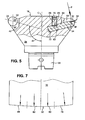
- Fig. 4 and 5 is a suitably designed for both a milling and a turning operation designed tool 18 in more detail.
- the tool 18 has in the manner of a cutter head a plurality of, in the illustrated embodiment, eight evenly distributed on the circumference of a tool body 24 milling cutting plate 22, which have a conical shape and provided on its larger-diameter end face each with a coating 26 of eg PCD which are one in plan view according to Fig. 5 seen annular milling cutter 28 forms.
- the milling cutters 28 Upon rotation of the tool 18 about the tool rotation axis C, the milling cutters 28 define in a plane perpendicular to the tool rotation axis C the already mentioned flight circle 20, which in Fig. 4 is shown with a circular line and whose diameter is greater than the largest diameter of the substantially conically tapered base body 24th
- each formed by a cutting plate 32 on a releasably secured to the base body 24 turning tool 34 and with respect to the circle 20 of the cutter cutting 28 are offset by a predetermined amount radially inward, as in Fig. 4 easy to recognize.
- the rotary cutting blades 30 are each offset radially inwards by approximately 0.2 mm in the direction of the tool rotation axis C, or spaced apart from the tool rotation axis C by 39.8 mm, so that they can not engage in a Fräsbearbeitungsvorgang with the recipe surface to be processed R of the spectacle lens L.
- the rotary blade 30 is located substantially at the height of the circle 20 of the cutter blades 28 in an imaginary plane parallel to a plane perpendicular to a through the tool rotation axis C. and the center axis M of the associated turning tool 34 extends in the plane spanned and contains the center axis M of the turning tool 34, while the cutter blades 28 each lie in a plane containing the tool rotation axis C.
- Fig. 4 The attachment of the milling cutting plates 22 on the base body 24 at its end remote from its in a conventional manner receiving portion 36 is in Fig. 4 shown on the left above by means of two risers. While in Fig. 4 lying on the right lying departure in a plane parallel to the plane was executed, which contains the center axis of the corresponding milling cutting plate 22 on the base 24 positioning pin 38, which lies in Fig. 4 left break in a plane that actually runs at an angle to the drawing plane and contains the central axis of the illustrated threaded pin 40, but was tilted to simplify the presentation in the drawing plane.
- the metallic base body 24 is provided on its outer circumference with uniformly angularly spaced, identically formed recesses 42, each having a plane surface 44 for the surface contact of the respective milling cutting plate 22.
- the position of the plane surface 44 and the thickness of the respective milling cutting plate 22 are matched to one another such that the cutter blade 28 of a milling cutting plate 22 placed on the plane surface 44 lies in a plane with the tool rotation axis C or is aligned radially with it ,
- a blind hole 46 is formed, which is the cylindrical pin 38 is pressed so that one end of the metallic pin 38 protrudes from the flat surface 44.
- the centrally provided with a bore 48 milling cutting plate 22 is placed on the plane of the 44 projecting end of the pin 38.
- the bore 48 of the milling cutting plate 22 is finally on the plane of the plan 44 facing away from the milling cutting plate 22 covered by the coating 26.
- each of the recesses 42 also has a sloping wall portion 50, in which a bore portion 52 is inserted, which serves to guide a cylindrical extension of a clamping claw 54.
- the bore section 52 of the base body 24 is adjoined by an internally threaded section 56, the central axis of which extends at an angle to the plane of the planar surface 44 of the recess 42 in extension of the central axis of the bore section 52.
- the clamping claw 54 has a running over its entire length inner threaded portion 58 with respect to the internal thread portion 56 in the base body 24 reverse pitch.
- the threaded pin 40 screwed into the female threaded sections 56, 58 is provided, starting from its ends, with mutually separated male thread sections of opposite pitch, ie a right-hand thread and a left-hand thread.
- the clamping claw 54 can be moved radially inward or outward, wherein the clamping claw 54 as a result of the angular adjustment of the central axis of the threaded pin 40 with respect to the planar surface 44 of the planar surface 44 approaches or 44 away from it.
- the milling cutting plate 22 can be clamped or clamped by means of the clamping claw 54 against the plane surface 44.
- Fig. 4 are the turning tools 34 seen in the circumferential direction of the tool 18 arranged approximately symmetrically between the cutter blades 28 adjacent milling cutting plates 22.
- the base body 24 has a recess 60 for each turning tool 34, starting from which a blind hole 62 for receiving a cross-sectionally circular shaft 64 of the turning tool 34 is inserted into the base body 24, like the Fig. 5 shows.
- the blind hole 62 extends in the radial direction, ie in the direction of the tool axis of rotation C, wherein the center axis of the blind hole 62 with the tool rotation axis C a predetermined angle, in the illustrated embodiment, an angle of approximately 75 °.
- the metallic shaft 64 of the turning tool 34 has an oblique recess 66 and an oblique Einschliff on which a provided with a hexagon grub screw 68 is applied, which screwed into a parallel to the tool axis of rotation C introduced into the base body 24 threaded bore 70 is.
- the grub screw 68 on the one hand removably fixes the turning tool 34 in the blind hole 62 of the main body 24 and, on the other hand, holds the turning tool 34 against the bottom 72 of the blind hole 62.
- the detachable or attached as a coating on the turning tool 34 cutting plate 32 may according to the respective requirements, in particular specific to the material to be machined, polycrystalline diamond (PCD), natural diamond or even carbide with or without wear protection coating.
- PCD polycrystalline diamond
- the geometry of the rotary blade 30 are in the Fig. 6 and 7 two different variants of the rotary blade 30 shown enlarged, which is already further developments of the simplest variant, according to which the rotary blade 30 over the entire cutting width has a constant curvature.
- the curvature in this case has a radius which corresponds essentially to the distance of the rotary blade 30 to the tool axis of rotation C, whereby during the turning operation Form errors due to a wrong angular position of the rotary blade 30 with respect to the recipe surface to be processed R of the spectacle lens L can be avoided. With the above numerical values this would be a radius of approx. 39.8 mm.
- rotary cutter 30 has two portions 74, 76, of which one, serving as a fine processing part portion 76 has a constant curvature having a radius which, as described above substantially the distance of the rotary blade 30 to the tool axis of rotation C corresponds, while the other, as Roughing portion serving part 74 has a constant curvature having a radius which is significantly smaller than the radius of the former portion 76 and, for example, 15 mm.
- the width ratio of the partial regions 74 and 76 in the transverse direction of the cutting tip 32 in the illustrated exemplary embodiment is approximately 2 (partial region 74) to 5 (partial region 76).
- the rotary blade 30 is even divided into four different sections 78, 80, 82 and 84 of different width, the curvature decreases from right to left.
- right-to-left radii could be 40 mm, 80 mm, 120 mm, and 200 mm.
- the overall width of the rotary cutting edge 30 in the transverse direction of the cutting tip 32 can nevertheless remain below 10 mm.
- this milling operation comprises a piercing operation, in which the tool 18, which rotates about the tool rotation axis C and the spectacle lens L rotating about the workpiece rotation axis B, are moved relative to one another in at least one of the two axial directions X and Y in such a position-controlled manner in that the milling cutters 28 generate an annular recess-shaped recess at least in the region of the outer edge of the spectacle lens L before the tool 18 is guided in a shaping operation along a spiral path via the spectacle lens L from outside to inside in order to remove further material. Random machining and the faceting of the spectacle lens L are optional, although preferably mitab Stammde operations in the milling process L.
- edge processing is carried out by means of the rotating tool 18, a processing of the spectacle lens blank, for example, to the predetermined by the spectacle frame shape peripheral contour, while in the faceting the upper or Inner peripheral edge of the eyeglass lens blank is bevelled by means of the rotating tool 18.
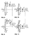
- the rotation of the tool 18 is first stopped, and then the rotary blade 30 of the tool 18 is brought into a predetermined angular position by rotation angle controlled rotation of the tool 18 about the tool rotation axis C.
- This condition is in Fig. 8 shown.
- a specific turning tool 34 with a cutting tip 32 made of a specific material or a specific region of the rotating cutting edge 30 with a specific curvature can be used here in accordance with the respective machining requirements by the rotational angle-controlled pivoting possibility of the tool 18 be applied to the prescription surface F of the spectacle lens L.
- a necessary chip removal for fine machining and to compensate for inaccuracies resulting from milling is thereby adjustable.
- the rotary blade 30 by position-controlled relative movement of the spectacle lens L and tool 18 in the two axial directions X and Y and rotational angle controlled rotation of the tool 18 about the tool axis of rotation C depending on the angular position of the spectacle lens L to the workpiece axis of rotation B along a spiral Way, which resembles in its form preferably the shape of an Archimedean spiral, led over the spectacle lens L.
- spiral distance is on the one hand smaller than the spiral distance of the spiral path in the upstream Fräsbearbeitungsvorgang to the Roughness of the machined surface F to keep within predetermined limits, but on the other hand greater than in conventional turning processes, due to the relatively large radius of the rotary blade 30, which also ensures a very small kinematic roughness of the generated surface F.
- the Fig. 9 illustrates in this context that in the turning operation, the position of the rotary blade 30 by CNC controlled rotation of the tool spindle 12 even when generating non-rotationally symmetric surfaces, in the illustrated method example, a toric surface F, always adapted to the respective curvature of the surface F. is that the rotary blade 30 tangentially to the surface to be machined F comes to rest. This is a CNC-controlled, continuous tracking of the rotary blade 30. Further shows a comparison of Fig. 9 with the Fig.
- the 10 and 11 finally illustrate the end of the turning process.
- the rotary blade 30 on its spiral path over the spectacle lens L, the optical axis the spectacle lens L has reached and the spectacle lens L has been rotated again by 360 °, the latter is moved away from the tool 18 in the Y-axis, so that the rotary blade 30 of the spectacle lens L is disengaged.
- a turning result is a (fine) turned, with respect to geometry accuracy and roughness extremely fine recipe surface F of polishing ready quality.
- workpiece and tool spindle position-controlled in two orthogonal axis directions X, Y are relatively movable.
- the tool by means of the tool spindle also navwinkelgeregelt about the tool axis of rotation C pivoted so that a tool provided on the rotary blade in dependence on the angular position of the spectacle lens with the surface to be processed of the spectacle lens in a defined Turning intervention can be brought.
- the invention also includes a combined milling and turning tool and a combined milling and turning method.
Description
Die vorliegende Erfindung bezieht sich auf ein Verfahren und eine Vorrichtung zur Flächenbearbeitung von Werkstücken aus nicht-sprödharten Materialien in der Optikfertigung gemäß den Oberbegriffen der Patentansprüche 1 bzw. 13 sowie auf ein Werkzeug dafür. Insbesondere bezieht sich die Erfindung auf die industrielle Bearbeitung von Rezeptflächen an Brillenlinsen aus Kunststoffen, wie Polycarbonat, CR39 und sogenannte "High Index" Materialien.The present invention relates to a method and a device for surface treatment of workpieces made of non-brittle-hard materials in the optical production according to the preambles of claims 1 and 13 and to a tool therefor. In particular, the invention relates to the industrial processing of prescription surfaces on spectacle lenses made of plastics, such as polycarbonate, CR39 and so-called "high index" materials.
Üblicherweise liegt bei dieser Bearbeitung ein aus Kunststoff spritzgegossener Brillenlinsenrohling, auch "Blank" genannt, vor, der eine standardisierte endbearbeitete konvexe Außenfläche mit z.B. sphärischer oder progressiver Form aufweist. Die in der Regel konkaven Innen- bzw. Rezeptflächen erhalten mittels spanender Bearbeitung eine sphärische, asphärische, torische, atorische, progressive oder Freiformgeometrie, je nach der gewünschten optischen Wirkung. Der typische konventionelle Ablauf bei der Innenflächenbearbeitung sieht nach dem Aufblocken des Brillenlinsenrohlings mit seiner Außenfläche auf einem Blockstück einen Fräs- oder Drehbearbeitungsprozeß zur Herstellung der optisch aktiven Form vor, gefolgt von einem Feinschleif- oder Polierprozeß zur Erzielung der notwendigen Oberflächengüte.Typically, this processing involves a plastic injection-molded spectacle lens blank, also called a blank, which has a standard finished convex outer surface with e.g. spherical or progressive shape. The generally concave interior or recipe surfaces obtained by machining a spherical, aspheric, toric, atoric, progressive or free-form geometry, depending on the desired optical effect. The typical conventional process in inner surface processing, after blocking the spectacle lens blank with its outer surface on a block piece, provides a milling or turning process for producing the optically active mold, followed by a finish grinding or polishing process to achieve the necessary surface finish.
Ein Verfahren und eine Vorrichtung zur Flächenbearbeitung von Werkstücken aus nicht-sprödharten Materialien in der Optikfertigung gemäß den Oberbegriffen der Ansprüche 1 bzw. 13 sind aus der
Aus diesem gattungsbildenden Stand der Technik der Anmelderin ist in diesem Zusammenhang ein Verfahren zur Erzeugung einer Oberfläche an einem Brillenlinsenrohling bekannt geworden, das sowohl für sprödharte Materialien als auch für Kunststoffe geeignet ist. Hierbei wird ein scheibenförmiges, rotationssymmetrisches Schleif- bzw. Fräswerkzeug verhältnismäßig großen Durchmessers verwendet, mit dessen Hilfe in mindestens zwei Arbeitsgängen, einem Einstech-Arbeitsgang für den hauptsächlichen Materialabtrag und einem formgebenden Arbeitsgang mit weiterer Materialabtragung entlang eines spiralförmigen Weges, das zu entfernende Rohlingmaterial mit hoher Schleif- bzw. Fräsleistung zerspant wird. Dabei resultiert aus dem letzten Arbeitsgang eine spiralförmig von außen nach innen verlaufende Bearbeitungsbahn mit geringer kinematischer Rauhigkeit bei relativ großem Spiralabstand. Die so erzeugte Oberfläche bedarf sodann nur geringer Feinschleif- und Poliernachbearbeitung. Wahlweise kann in dieses Verfahren sogar sowohl ein an die Brillengestellform anpassender Randbearbeitungsvorgang als auch ein den Brillenglasrand facettierender Arbeitsgang integriert sein.In this context, a method for producing a surface on a spectacle lens blank which is suitable both for brittle-hard materials and for plastics is known from this generic state of the art of the applicant. In this case, a disk-shaped, rotationally symmetrical grinding or milling tool of relatively large diameter is used, with the help in at least two operations, a piercing operation for the main material removal and a shaping operation with further material removal along a spiral path, the blank material to be removed with high Grinding or milling power is machined. This results from the last operation, a spiral running from outside to inside machining path with low kinematic roughness at a relatively large spiral distance. The surface thus produced then requires only little fine grinding and polishing finishing. Optionally, this process can even integrate both an edging process adapted to the shape of the spectacle frame and an operation facetizing the spectacle lens edge.
Obgleich mit diesem vorbekannten Verfahren eine sehr gute Zerspanungsleistung und demgemäß kurze, industriellen Anforderungen genügende Bearbeitungszeiten erzielt werden können, wäre es für bestimmte Anwendungsfälle wünschenswert, eine noch höhere Oberflächenqualität vor der Feinschleif- bzw. Poliernachbearbeitung zu erzielen, insbesondere bei komplexen optischen Flächen, wie asphärischen, atorischen oder progressiven bzw. Freiformflächen. Bei diesen Flächenformen können nämlich keine Feinschleifprozesse nachgeschaltet werden, die formgebundene Werkzeuge verwenden. Vielmehr müssen derartige Flächen in der Regel unter Verwendung flexibler Polierwerkzeuge poliert werden, wobei dies um so besser und effizienter geschehen kann, je weniger Polierabtrag erforderlich ist. Im Idealfall könnte bei Flächen mit sehr hoher Oberflächenqualität ein nachgeschalteter Feinschleif- oder Polierprozeß eventuell sogar gänzlich entfallen, wobei dann eine dem Polieren angenäherte optische Qualität durch ein nachgeschaltetes Beschichtungsverfahren, auch "Cut & Coat" Verfahren genannt, erhalten werden könnte (siehe z.B.
Des weiteren sind -- wie eingangs bereits erwähnt -- auch Drehbearbeitungsverfahren bekannt, die der Erzeugung von Rezeptflächen an Brillenlinsenrohlingen aus Kunststoff dienen. In diesem Zusammenhang sei beispielsweise auf die Druckschriften
Schließlich offenbart die
Ausgehend vom Stand der Technik nach der
Diese Aufgabe wird durch die in den Patentansprüchen 1, 7 bzw. 13 angegebenen Merkmale gelöst. Vorteilhafte bzw. zweckmäßige Weiterbildungen der Erfindung sind Gegenstand der Patentansprüche 2 bis 6, 8 bis 12 und 14.This object is achieved by the features specified in the patent claims 1, 7 and 13, respectively. Advantageous or expedient developments of the invention are subject matter of the claims 2 to 6, 8 to 12 and 14.
Nach einem im Patentanspruch 1 angegebenen Grundgedanken der Erfindung schließt sich bei einem Verfahren zur Flächenbearbeitung von Werkstücken aus nicht-sprödharten Materialien in der Optikfertigung, wie Brillenlinsen aus Kunststoff, bei welchem das im Drehwinkel geregelt um eine Werkstück-Drehachse B rotierende Werkstück einem Fräsbearbeitungsvorgang durch ein Werkzeug ausgesetzt wird, das um eine mit der Werkstück-Drehachse B einen vorbestimmten Winkel einschließende Werkzeug-Drehachse C rotiert, wobei das Werkstück und das Werkzeug in wenigstens einer von zwei rechtwinklig verlaufenden Achsrichtungen X, Y derart lagegeregelt relativ zueinander bewegt werden, daß das Werkzeug während eines Einstech-Arbeitsgangs mindestens im Bereich des Außenrands des Werkstücks eine ringmuldenförmige Ausnehmung erzeugt, bevor das Werkzeug in einem formgebenden Arbeitsgang entlang eines spiralförmigen Weges über das Werkstück weiteres Material abträgt, an diesen Fräsbearbeitungsvorgang ein Drehbearbeitungsvorgang an, bei dem eine am Werkzeug vorgesehene Drehschneide durch eine lagegeregelte Relativbewegung von Werkstück und Werkzeug in wenigstens einer der zwei Achsrichtungen X, Y und eine im Drehwinkel geregelte Schwenkbewegung des Werkzeugs um die Werkzeug-Drehachse C tangential an die zu bearbeitende Fläche des im Drehwinkel geregelt um die Werkstück-Drehachse B gedrehten Werkstücks angelegt und im Drehbearbeitungseingriff entlang eines spiralförmigen Weges über das Werkstück geführt wird.After a specified in claim 1 basic idea of the invention closes in a process for surface treatment of workpieces made of non-brittle materials in optics production, such as plastic lenses, in which the controlled angle of rotation about a workpiece axis of rotation B workpiece rotating a Fräsbearbeitungsvorgang by a Tool is rotated, which rotates about a with the workpiece rotation axis B at a predetermined angle enclosing tool rotation axis C, wherein the workpiece and the tool in at least one of two orthogonal axis directions X, Y be moved relative to each other so that the tool during a piercing operation at least in the region of the outer edge of the workpiece generates an annular recess before the tool ablates further material in a shaping operation along a spiral path over the workpiece, to this Fräsbearbeitungsvorgang a turning operation in which a tool provided on the rotary blade by a position-controlled relative movement of the workpiece and tool in at least one of the two axial directions X, Y and controlled in the rotational angle pivotal movement of the tool about the tool axis of rotation C tangentially to the surface to be machined controlled in the rotation angle applied to the workpiece rotation axis B rotated workpiece and is guided in the rotary machining engagement along a spiral path over the workpiece.
Weiterhin sieht die Erfindung nach der Lehre des Patentanspruchs 7 insbesondere für die Durchführung des obigen Verfahrens ein Werkzeug zur Flächenbearbeitung von Werkstücken aus nicht-sprödharten Materialien in der Optikfertigung, wie Brillenlinsen aus Kunststoff, vor, das einen Grundkörper aufweist, an dem eine Mehrzahl von Fräserschneiden vorgesehen ist, die bei einer Drehung des Werkzeugs um eine Werkzeug-Drehachse C in einer Ebene senkrecht zur Werkzeug-Drehachse C einen Flugkreis definieren, wobei am Grundkörper auch mindestens eine Drehschneide vorgesehen ist, die gegenüber dem Flugkreis der Fräserschneiden um einen vorbestimmten Betrag nach radial innen versetzt angeordnet ist, und wobei die Drehschneide eine konstante Krümmung mit einem Radius hat, der im wesentlichen dem Abstand der Drehschneide zur Werkzeug-Drehachse C entspricht, oder Teilbereiche von verschiedener, jeweils konstanter Krümmung aufweist, von denen ein Teilbereich eine konstante Krümmung mit einem Radius hat, der im wesentlichen dem Abstand der Drehschneide zur Werkzeug-Drehachse C entspricht.Furthermore, the invention provides according to the teaching of claim 7, in particular for the implementation of the above method, a tool for surface machining of workpieces of non-brittle materials in optics production, such as plastic eyeglass lenses, before, which has a base body on which a plurality of cutters is provided, which define at a rotation of the tool about a tool axis of rotation C in a plane perpendicular to the tool axis of rotation C a circle, wherein the base body and at least one rotary blade is provided, compared to the circle of the cutter blades by a predetermined amount radially is arranged offset inside, and wherein the rotary blade has a constant curvature having a radius which substantially corresponds to the distance of the rotary blade to the tool axis of rotation C, or portions of different, each having a constant curvature, of which a portion of a constant curvature with a m radius, which corresponds substantially to the distance of the rotary blade to the tool axis of rotation C.
Schließlich ist erfindungsgemäß bei der im Oberbegriff des Patentanspruchs 13 angegebenen, insbesondere für die Durchführung des obigen Verfahrens unter Verwendung insbesondere des obigen Werkzeugs geeigneten Vorrichtung zur Flächenbearbeitung von Werkstücken aus nicht-sprödharten Materialien in der Optikfertigung, wie Brillenlinsen aus Kunststoff, die eine Werkstückspindel hat, mittels der das Werkstück im Drehwinkel geregelt um eine Werkstück-Drehachse B drehend antreibbar ist, und eine Werkzeugspindel aufweist, mittels der das Werkzeug um eine Werkzeug-Drehachse C drehend antreibbar ist, welche mit der Werkstück-Drehachse B einen vorbestimmten Winkel einschließt, wobei Werkstück- und Werkzeugspindel lagegeregelt in zwei rechtwinklig verlaufenden Achsrichtungen X, Y relativ zueinander bewegbar sind, für eine Drehbearbeitung der zu bearbeitenden Fläche des Werkstücks das Werkzeug mittels der Werkzeugspindel im Drehwinkel geregelt um die Werkzeug-Drehachse C verschwenkbar, so daß eine am Werkzeug vorgesehene Drehschneide in Abhängigkeit von der Drehwinkelstellung des Werkstücks mit der zu bearbeitenden Fläche des Werkstücks in einen definierten Drehbearbeitungseingriff bringbar ist.Finally, according to the invention in the specified in the preamble of claim 13, in particular for carrying out the above method using in particular the above tool suitable device for surface machining of workpieces of non-brittle materials in optics production, such as plastic lenses, which has a workpiece spindle, by means of which the workpiece controlled in rotation angle about a workpiece axis of rotation B is rotationally driven, and a tool spindle, by means of which the tool is rotatably driven about a tool axis of rotation C, which includes a predetermined angle with the workpiece axis of rotation B, wherein workpiece - And tool spindle position-controlled in two orthogonal axes X, Y are relatively movable, for a turning of the machined surface of the workpiece, the tool by means of the tool spindle in the rotation angle controlled about the tool rotation axis C pivot bar, so that a tool provided on the rotary cutting edge in dependence on the rotational angle position of the workpiece with the surface to be machined of the workpiece in a defined rotational machining engagement can be brought.
Im Kern stellt die Erfindung verfahrensseitig also darauf ab, den bewährten Fräsbearbeitungsvorgang, bei dem große Materialmengen des Werkstücks, z.B. des Brillenlinsenrohlings, in sehr kurzer Zeit zerspant werden können, mit einem sich daran anschließenden, speziellen (Fein)Drehbearbeitungsvorgang zu kombinieren, welcher der Erzielung einer höheren Oberflächenqualität dient. Hierbei werden durch den Drehbearbeitungsvorgang ggf. nachfolgende Bearbeitungsschritte störende Fräsriefen beseitigt, die während des Fräsbearbeitungsvorgangs infolge des diskontinuierlichen Bearbeitungseingriffs der einzelnen Fräserschneiden bzw. des unterbrochenen Schnitts durch die Fräserschneiden auf der bearbeiteten Fläche des Werkstücks in Richtung der Mittelachse im wesentlichen senkrecht zur Spiralbahn erzeugt werden. Werkzeugseitig wird ein Werkzeug vorgeschlagen, das quasi eine Kombination von Fräser und Drehschneiden- bzw. -meißelrevolver darstellt, wobei die wenigstens eine Drehschneide des Werkzeugs in radialer Richtung gesehen hinter dem Flugkreis der Fräserschneiden zurücksteht, so daß die Drehschneide bei einer kontinuierlichen Drehung des Werkzeugs während eines Fräsbearbeitungsvorgangs nicht mit dem Werkstück in Bearbeitungseingriff gelangen kann. Für einen sich an den Fräsbearbeitungsvorgang anschließenden Drehbearbeitungsvorgang ist das Werkzeug zunächst zu stoppen und sodann mit seiner Drehschneide bezüglich der zu bearbeitenden Werkstückfläche winkelzupositionieren. Die Drehschneide kann somit auch unabhängig von den Fräserschneiden hinsichtlich der Schneidengeometrie (Schneidenradius, Spanwinkel) sowie dem Schneidenmaterial gestaltet und demgemäß optimal an das Werkstückmaterial angepaßt werden. Hierbei hat die Drehschneide eine konstante Krümmung mit einem Radius, der im wesentlichen dem Abstand der Drehschneide zur Werkzeug-Drehachse C entspricht, oder weist Teilbereiche von verschiedener, jeweils konstanter Krümmung auf, von denen ein Teilbereich eine konstante Krümmung mit einem Radius hat, der im wesentlichen dem Abstand der Drehschneide zur Werkzeug-Drehachse C entspricht. Durch diese Ausgestaltung der Drehschneide werden auf vorteilhaft einfache Weise Formfehler an der bearbeiteten Fläche des Werkstücks zuverlässig vermieden, die ggf. durch eine falsche Winkellage der Drehschneide hervorgerufen werden könnten. Mit anderen Worten gesagt sind somit Fehler bei der Schwenkpositionierung der Drehschneide für die Drehbearbeitung in vorteilhafter Weise vernachlässigbar. Vorrichtungsseitig wird schließlich die bekannte, in den zwei Linearachsen X und Y lagegeregelte sowie in der Werkstück-Drehachse B drehwinkelgeregelte Vorrichtung in einfacher Weise um eine weitere (CNC-)geregelte Achse ergänzt, nämlich die drehwinkelgeregelte Werkzeug-Drehachse C. Dies gestattet eine Schwenkpositionierung des Werkzeugs bezüglich der zu bearbeitenden Fläche des Werkstücks, so daß die Drehschneide des Werkzeugs stets in einen definierten Drehbearbeitungseingriff mit der zu bearbeitenden Fläche des Werkstücks gebracht werden kann, beispielsweise derart, daß dabei eine an die Drehschneide angelegte Tangente stets mit einer an die zu bearbeitende Fläche angelegten Tangente zusammenfällt. In Summe kann die zu bearbeitende Fläche des Werkstücks mit nur einem Werkzeug, welches neben Fräserschneiden auch wenigstens eine Drehschneide aufweist, in nur einer Vorrichtung und einer Aufspannung des Werkstücks sowohl einem Fräsbearbeitungsvorgang mit einem verhältnismäßig großen Zerspanungsvolumen als auch einem (Fein) Drehbearbeitungsvorgang unterworfen werden, so daß Flächen von beliebiger Geometrie mit hoher Qualität, d.h. makrogeometrisch gesehen verbesserter Geometriegenauigkeit und mikrogeometrisch gesehen geringstmöglicher Randzonenschädigung schnell und zuverlässig bearbeitet werden können.At the heart of the invention, therefore, the method aims to combine the proven milling process, in which large quantities of material of the workpiece, eg the spectacle lens blank, can be machined in a very short time, with an adjoining, special (fine) turning operation, which achieves a higher surface quality is used. In this case, the subsequent machining steps disturbing Fräsriefen be eliminated during the Fräsbearbeitungsvorgang due to the discontinuous machining engagement of the individual cutter blades or the interrupted section by the cutter cutting on the machined surface of the workpiece in the direction of the central axis substantially perpendicular to the spiral path be generated. On the tool side, a tool is proposed, which is quasi a combination of cutter and Drehschneiden- or -meißelrevolver, wherein the at least one rotary blade of the tool seen in the radial direction is behind the circle of the cutter cutters, so that the rotary blade during a continuous rotation of the tool during a Fräsbearbeitungsvorgangs can not get into machining engagement with the workpiece. For a subsequent turning operation to the milling operation, the tool must first be stopped and then angularly positioned with its rotary cutting edge with respect to the workpiece surface to be machined. The rotary cutting edge can thus also be designed independently of the milling cutters with regard to the cutting edge geometry (cutting radius, rake angle) as well as the cutting material and, accordingly, optimally adapted to the workpiece material. In this case, the rotary cutting edge has a constant curvature with a radius that essentially corresponds to the distance of the rotary cutting edge from the tool rotation axis C, or has subregions of different, respectively constant curvature, of which a subarea has a constant curvature with a radius which is in the essentially corresponds to the distance of the rotary cutting to the tool axis of rotation C. This embodiment of the rotary cutting reliably reliably prevents form errors on the machined surface of the workpiece, which could possibly be caused by a wrong angular position of the rotary cutting edge. In other words, errors in the pivotal positioning of the rotary cutting edge for the turning operation are thus advantageously negligible. On the device side, finally, the known device, which is position-controlled in the two linear axes X and Y and rotationally-controlled in the workpiece rotation axis B, is simply supplemented by a further (CNC) controlled axis, namely the rotational angle-controlled tool rotation axis C. This permits pivoting positioning of the tool Tool with respect to the surface to be machined of the workpiece, so that the rotary cutting edge of the tool can always be brought into a defined Drehendesgeingriff with the surface to be machined of the workpiece, for example, such that a tangent to the rotary blade always coincides with a tangent applied to the surface to be machined. In sum, the surface of the workpiece to be machined with only one tool, which besides milling cutters also has at least one rotary cutting edge, can be subjected to both a milling operation with a relatively large cutting volume and a (fine) turning operation in only one device and one clamping of the workpiece. so that surfaces of any geometry with high quality, ie macrogeometrically seen improved geometrical inaccuracy and microgeometrically seen least possible edge zone damage can be processed quickly and reliably.
Gemäß dem Patentanspruch 2 ist vorgesehen, daß bei dem Drehbearbeitungsvorgang wenigstens ein Teilbereich einer Drehschneide des Werkzeugs mit der zu bearbeitenden Fläche des Werkstücks in Drehbearbeitungseingriff gebracht wird, wobei zumindest der in Drehbearbeitungseingriff gebrachte Teilbereich der Drehschneide gleich oder nur geringfügig stärker gekrümmt ist als die zu bearbeitende Fläche. Da erfindungsgemäß die Drehschneide auch definiert verschwenkt und somit tangential an die zu bearbeitende Fläche des Werkstücks angelegt werden kann, kann hier in kostengünstiger Weise selbst eine relativ schmale Drehschneide eine relativ flache Krümmung bzw. einen großen Radius aufweisen, anders als die im Stand der Technik verwendeten Drehschneiden, die eine sehr starke Krümmung bzw. einen sehr kleinen Radius aufweisen müssen, damit sie bei lediglich linearer Zustellung eine definierte Geometrie am Werkstück, insbesondere Brillenlinsen mit stark gekrümmten Rezeptflächen erzeugen können. Die somit erst durch die Erfindung mit vertretbarem Aufwand mögliche Verwendung von Drehschneiden mit im Verhältnis flachen Krümmungen hat darüber hinaus den Vorteil, daß bei der Drehbearbeitung Spiralbahnen mit relativ großen Spiralabständen ohne hohe Dynamik der Zustellbewegungen gefahren werden können, was nicht nur die Drehbearbeitung gegenüber herkömmlichen Drehbearbeitungsprozeßen bei wenigstens gleicher Qualität der erzeugten Oberflächen beschleunigt sondern auch geringere Anforderungen an die verwendete Vorrichtung stellt.According to claim 2, it is provided that in the turning operation, at least a portion of a rotary cutting of the tool is brought into rotational machining engagement with the surface to be machined of the workpiece, wherein at least the brought into turning processing portion of the rotary blade is the same or only slightly more curved than the machined Area. Since, in accordance with the invention, the rotary cutting edge also pivots in a defined manner and can thus be applied tangentially to the surface of the workpiece to be machined, even a relatively narrow rotary cutting edge can have a relatively flat curvature or a large radius here in a cost-effective manner, unlike those used in the prior art Rotary cutting, which must have a very strong curvature or a very small radius, so that they can produce a defined geometry on the workpiece, in particular spectacle lenses with highly curved prescription surfaces with only linear delivery. The thus possible by the invention with reasonable effort possible use of rotary cutters with relatively flat curvatures also has the advantage that in the Turning spiral tracks with relatively large spiral distances can be driven without high dynamics of Zustellbewegungen, which not only speeds up the turning compared to conventional turning processes at least the same quality of the surfaces produced but also makes lower demands on the device used.
Auch das im Patentanspruch 3 angegebene Vorgehen bei dem Drehbearbeitungsvorgang baut in vorteilhafter Weise darauf auf, daß die Drehschneide nach der Erfindung relativ zu der zu bearbeitenden Fläche des Werkstücks definiert verschwenkt werden kann. Demgemäß wird bei dem Drehbearbeitungsvorgang wenigstens ein Teilbereich einer Drehschneide des Werkzeugs mit der zu bearbeitenden Fläche des Werkstücks in Drehbearbeitungseingriff gebracht, wobei das Werkzeug für weitere Drehbearbeitungsvorgänge in Abhängigkeit vom Verschleiß der Drehschneide um die Werkzeug-Drehachse im Drehwinkel geregelt verschwenkt wird, um einen anderen Teilbereich dieser Drehschneide oder wenigstens einen Teilbereich einer anderen Drehschneide mit der zu bearbeitenden Fläche des Werkstücks in Drehbearbeitungseingriff zu bringen. Der Drehschneidenverschleiß könnte hierbei beispielsweise über eine Messung der erzeugten Fläche und einen sich anschließenden Vergleich zwischen dem Soll- und dem Istzustand des Bearbeitungsergebnisses ermittelt werden.Also specified in claim 3 procedure in the turning operation builds advantageously on the fact that the rotary blade according to the invention relative to the surface to be machined of the workpiece can be pivoted defined. Accordingly, in the turning machining operation, at least a portion of a rotary cutting edge of the tool is brought into rotary machining engagement with the surface of the workpiece to be machined, the tool being pivoted in rotation angle to another portion for further turning operations depending on the wear of the rotary cutting edge about the tool rotation axis bring this rotary blade or at least a portion of another rotary blade with the surface to be machined of the workpiece in rotational machining engagement. The rotary cutting wear could be determined in this case, for example, via a measurement of the generated surface and a subsequent comparison between the desired state and the actual state of the processing result.
Nach der Lehre des Patentanspruchs 4 wird für den Drehbearbeitungsvorgang am Werkzeug eine Drehschneide eingesetzt, die, wie auch im Patentanspruch 7 bzw. 9 angegeben, unterschiedlich gekrümmte Teilbereiche aufweist, wobei das Werkzeug in Abhängigkeit von dem gewünschten Zerspanungsvolumen und der gewünschten Oberflächenqualität der bearbeiteten Fläche des Werkstücks derart um die Werkzeug-Drehachse C im Drehwinkel geregelt verschwenkt wird, daß für ein im Verhältnis großes Zerspanungsvolumen ein stärker gekrümmter Teilbereich der Drehschneide mit der zu bearbeitenden Fläche des Werkstücks in Drehbearbeitungseingriff gebracht wird, während für eine im Verhältnis hohe Oberflächenqualität ein schwächer gekrümmter Teilbereich der Drehschneide mit der zu bearbeitenden Fläche des Werkstücks in Drehbearbeitungseingriff gebracht wird. So kann den jeweiligen Erfordernissen entsprechend die Drehbearbeitung unter in vorteilhafter Weise vorwählbaren Gesichtspunkten erfolgen, ohne daß dazu das Werkzeug zu wechseln wäre. Insbesondere in herstellungstechnischer Hinsicht zweckmäßig ist hierbei die im Patentanspruch 9 angegebene Ausbildung des Werkzeugs, gemäß der die Drehschneide Teilbereiche von verschiedener, jeweils konstanter Krümmung aufweist, wobei die Krümmung in Drehrichtung des Werkzeugs gesehen ausgehend von einem Ende der Drehschneide zum anderen Ende der Drehschneide von Teilbereich zu Teilbereich kontinuierlich abnimmt.According to the teaching of claim 4, a rotary blade is used for the turning machining process on the tool, which, as in the claims 7 and 9 indicated differently curved portions, wherein the tool depending on the desired cutting volume and the desired surface quality of the machined surface of the Workpiece is pivoted so controlled about the tool rotation axis C in the rotation angle, that for a relatively large cutting volume, a more curved portion of the rotary blade with the surface to be machined of the workpiece in turning processing is brought, while for a relatively high surface quality, a weaker curved portion of the rotary blade is brought into rotational machining engagement with the surface to be machined of the workpiece. Thus, the respective requirements according to the turning can be done under advantageously preselectable aspects, without the need to change the tool. Particularly expedient in terms of manufacturing technology here is the specified in claim 9 training of the tool, according to which the rotary cutting portions of different, each having constant curvature, the curvature seen in the direction of rotation of the tool, starting from one end of the rotary blade to the other end of the rotary cutting of partial area to partial area decreases continuously.
Der Patentanspruch 5 sieht vor, daß bei dem Drehbearbeitungsvorgang eine mit der zu bearbeitenden Fläche im Drehbearbeitungseingriff befindliche Drehschneide entlang eines spiralförmigen Weges über das Werkstück geführt wird, der in regelungstechnisch einfacher Weise eine Form ähnlich einer archimedischen Spirale aufweist. Dies ermöglicht in vorteilhafter Weise auch im wesentlichen konstante Schnittgeschwindigkeiten während des Drehbearbeitungsvorgangs, ohne daß hierfür ein hoher regelungstechnischer Aufwand betrieben werden müßte. Alternativ dazu ist es aber auch denkbar, während des Drehbearbeitungsvorgangs Spiralbahnen zu fahren, die eine in einer der Achsrichtungen X, Y gestauchte Form aufweisen. Um die Dynamik der Zustellbewegungen abzuschwächen, würde sich hier eine Stauchung der Form der gefahrenen Spiralbahn in der Achsrichtung anbieten, in der während des Drehbearbeitungsvorgangs die beteiligten Bauelemente der Vorrichtung mit oder gegen die Schwerkraft bewegt werden müssen.The patent claim 5 provides that in the turning processing a located with the surface to be machined in the Drehbearbeitungseingriff rotary blade along a spiral path over the workpiece is performed, which has a shape similar to an Archimedean spiral in simple control manner. This advantageously allows substantially constant cutting speeds during the turning operation, without the need for a high control engineering effort would be operated. Alternatively, it is also conceivable to travel during the turning operation spiral paths, which have a compressed in one of the axial directions X, Y shape. In order to mitigate the dynamics of the feed movements, a compression of the shape of the spiral path traveled in the axial direction would offer here, in which the involved components of the device must be moved with or against gravity during the turning operation.
Ein weiterer wesentlicher Vorteil des erfindungsgemäßen, aus einem bestimmten Fräsbearbeitungsvorgang und einem sich daran anschließenden speziellen Drehbearbeitungsvorgang kombinierten Verfahrens ist darin zu sehen, daß das von reinen Drehverfahren her bekannte Problem der Entstehung eines Fließspanes, und damit der Spanabfuhr nicht besteht, welches insbesondere bei zähen Kunststoffen, wie Polycarbonat, nicht zu unterschätzen ist. Vor allem bei mannloser, vollautomatischer Bearbeitung kann es durch einen Fließspan zum Spänestau und daraus resultierenden Maschinenausfällen kommen. Bei Brillenlinsen-Drehmaschinen wird aus diesem Grund oftmals eine Späneabsaugung mit integriertem Häcksler eingesetzt. Derartige Einrichtungen erübrigen sich bei dem erfindungsgemäßen Bearbeitungsverfahren in vorteilhafter Weise. Während des anfänglichen Fräsbearbeitungsvorgangs entstehen kurze Späne, deren Abfuhr keinerlei Probleme bereitet; beim nachfolgenden Drehbearbeitungsvorgang entsteht nicht zuletzt aufgrund der wie oben beschrieben möglichen, nur schwach gekrümmten Drehschneide ein sehr dünner, relativ breiter Fließspan, der infolge der mit abgetragenen Fräsriefen, die quasi Sollbruchstellen des Spanes darstellen, örtlich geschwächt ist und deshalb relativ leicht zerbricht. Wie Versuche der Anmelderin gezeigt haben, läßt sich der beim Drehbearbeitungsvorgang entstehende Fließspan besonders leicht zerstückeln, wenn, wie im Patentanspruch 6 angegeben, während des Drehbearbeitungsvorgangs ein Hochdruck-Kühlmittelstrahl auf die Bearbeitungseingriffsstelle zwischen Werkzeug und Werkstück gerichtet wird.Another significant advantage of the invention, from a particular milling operation and a him subsequent special turning process combined process is the fact that the known pure rotary method problem of the formation of a flow chip, and thus the chip removal does not exist, which in particular in tough plastics, such as polycarbonate, should not be underestimated. Especially with unmanned, fully automatic processing, it can come through a flow chip for chip accumulation and resulting machine failures. In the case of eyeglass lens lathes, chip evacuation with integrated shredder is therefore often used for this reason. Such devices are unnecessary in the processing method according to the invention in an advantageous manner. During the initial milling process, short chips are produced whose removal causes no problems; in the subsequent turning process is not least due to the possible as described above, only slightly curved rotary blade a very thin, relatively wide flow chip, which is weakened locally due to the eroded with milling grooves, which are quasi predetermined breaking points of the chip and therefore relatively easy breaks. As the Applicant's experiments have shown, the flow chip produced during the turning process is particularly easy to dismember when, as indicated in claim 6, a high-pressure coolant jet is directed onto the machining engagement point between the tool and the workpiece during the turning operation.
Nach der Lehre des Patentanspruchs 8 sind am Grundkörper mehrere Drehschneiden vorgesehen, die vorzugsweise gleichmäßig am Umfang des Grundkörpers verteilt sind. Somit können in vorteilhafter Weise z.B. untereinander verschiedene Drehschneiden, die hinsichtlich ihrer Geometrie und/oder des Drehschneidenmaterials individuell an die zu erzeugende Werkstückgeometrie und/oder an das zu zerspanende Material des Werkstücks angepaßt sind, an einem Werkzeug eingesetzt werden, so daß selbst für die Bearbeitung von in Geometrie bzw. Werkstoff verschiedenen Werkstücken das Werkzeug nicht gewechselt werden muß. Eine gleichmäßige Verteilung der Drehschneiden am Umfang des Grundkörpers hat den Vorteil, daß infolge der Drehschneiden keine Unwuchten entstehen, die bei einem Einsatz des Werkzeugs als Fräser der Oberflächenqualität der erzeugten Fläche abträglich sein könnten.According to the teaching of claim 8, a plurality of rotary blades are provided on the base body, which are preferably distributed uniformly on the circumference of the base body. Thus, advantageously, for example, with each other different rotary cutters, which are adapted individually with respect to their geometry and / or the rotary cutting material to the workpiece geometry to be generated and / or to the material to be machined workpiece are used on a tool, so that even for machining of different in geometry or material workpieces the tool does not have to be changed. A uniform distribution of the rotary blades on the circumference of the body has the advantage that due to the rotary blades no imbalances arise that could be detrimental to a use of the tool as a router of the surface quality of the surface generated.
Der Patentanspruch 10 sieht vor, daß die Drehschneide zwei Teilbereiche hat, von denen der eine Teilbereich eine konstante Krümmung mit einem Radius aufweist, der im wesentlichen dem Abstand der Drehschneide zur Werkzeug-Drehachse C entspricht, wodurch sich bei der Drehbearbeitung die obigen Vorteile ergeben, während der andere Teilbereich eine konstante Krümmung mit einem Radius aufweist, der deutlich kleiner ist als der Radius des erstgenannten Teilbereichs. Bei dieser Ausgestaltung der Drehschneide kann der einen kleineren Radius aufweisende Teilbereich als Einlaufbereich vorteilhaft dem Grobzerspanen der nach dem Fräsbearbeitungsvorgang noch vorhandenen kinematischen Rauhigkeit der bearbeiteten Fläche des Werkstücks dienen, während der einen größeren Radius aufweisende Teilbereich während des Drehbearbeitungsvorgangs als geometriebestimmender Bereich zum Schlichten eingesetzt werden kann.
Zweckmäßig ist die Drehschneide durch ein Schneidplättchen an einem Drehmeißel ausgebildet, der lösbar am Grundkörper befestigt ist, wie im Patentanspruch 11 angegeben, so daß der Drehmeißel zum Ersatz durch einen anderen Drehmeißel oder zum Nacharbeiten austauschbar ist.Suitably, the rotary blade is formed by a cutting plate on a turning tool, which is releasably secured to the base body, as indicated in claim 11, so that the turning tool is exchangeable for replacement by another turning tool or rework.
Nach der Lehre des Patentanspruchs 12 ist in einer vorteilhaft einfachen Ausgestaltung des Werkzeugs der Grundkörper mit einem Sackloch zur Aufnahme eines im Querschnitt kreisförmigen Schafts des Drehmeißels versehen, wobei der Schaft eine schräge Aussparung aufweist, an dem eine in eine Gewindebohrung des Grundkörpers einschraubbare Schraube anliegt, um den Drehmeißel lösbar am Grundkörper zu befestigen und auf Anschlag gegen den Boden des Sacklochs zu halten. Die Längenabstimmung des Drehmeißels kann hier in einfacher Weise in der Bearbeitungsvorrichtung erfolgen, nachdem der Drehmeißel entsprechend dem Werkstück positioniert wurde. Dabei wird z.B. eine Brillenlinse gedreht und sodann deren Mittendicke gemessen. Falls die korrekte Mittendicke nicht erreicht wird, kann das Maß, um das der Drehmeißel bei der Drehbearbeitung zu lang oder zu kurz war, bei Folgebearbeitungen durch entsprechende Regelung der Achsen der Vorrichtung CNC-technisch kompensiert werden.According to the teaching of
Schließlich sind gemäß dem Patentanspruch 14 sowohl die Werkstückspindel als auch die Werkzeugspindel horizontal ausgerichtet. Diese Anordnung wird bevorzugt, weil dadurch die Beschickung der Vorrichtung und der Spanabtransport während der Bearbeitung vereinfacht werden. Denkbar ist jedoch auch eine massendynamisch optimierte Ausrichtung der Werkstück- und Werkzeugspindeln derart, daß bei der Bearbeitung keine der Spindeln mit oder gegen die Schwerkraft bewegt werden muß.Finally, according to
Im folgenden wird die Erfindung anhand bevorzugter Ausführungsbeispiele unter Bezugnahme auf die beigefügten, zum Teil schematischen Zeichnungen näher erläutert. Darin zeigen:
-
Fig. 1 eine erfindungsgemäße Vorrichtung zur Flächenbearbeitung von Brillenlinsen aus Kunststoff in einer schematischen, teilweise geschnittenen und abgebrochenen Vorderansicht, in der Werkstück und Werkzeug sich in einem Fräsbearbeitungseingriff befinden und vier CNC-geregelte Achsen, nämlich eine Linearachse Y für das Werkstück, eine dazu rechtwinklig verlaufende Linearachse X für das Werkzeug, eine drehwinkelgeregelte Werkstück-Drehachse B und eine drehwinkelgeregelte Werkzeug-Drehachse C angedeutet sind; -
Fig. 2 eine schematische, abgebrochene Seitenansicht der inFig. 1 dargestellten Vorrichtung von rechts inFig. 1 ; -
Fig. 3 eine schematische, teilweise geschnittene und abgebrochene Draufsicht auf die inFig. 1 dargestellte Vorrichtung von oben inFig. 1 ; -
Fig. 4 eine aufgebrochene Stirnansicht eines erfindungsgemäßen Werkzeugs zur Flächenbearbeitung von Brillenlinsen aus Kunststoff, welches neben einer Mehrzahl von gleichmäßig am Umfang verteilten Fräs-Schneidplättchen zwei symmetrisch angeordnete Drehmeißel aufweist; -
Fig. 5 eine Schnittansicht des inFig. 4 gezeigten Werkzeugs entsprechend der Schnittverlaufslinie V-V inFig. 4 , in der zur Vereinfachung der Darstellung lediglich eines der Fräs-Schneidplättchen gezeigt ist; -
Fig. 6 eine vergrößerte Draufsicht auf die Drehschneide eines Drehmeißels des in denFig. 4 und5 gezeigten Werkzeugs entsprechend dem Detailausschnitt D inFig. 4 in Richtung des Pfeils P inFig. 5 gesehen; -
Fig. 7 eine in der Darstellungsweise derFig. 6 entsprechende, vergrößerte Draufsicht auf die Drehschneide eines Drehmeißels in einer alternativen Ausgestaltung; und -
Fig. 8 bis 11 prinzipielle Darstellungen, die einen Drehbearbeitungsvorgang zur Bearbeitung einer torischen Fläche an einer geschnitten gezeigten Brillenlinse mittels einer erfindungsgemäßen Vorrichtung unter Verwendung eines erfindungsgemäßen Werkzeugs in einer Vorderansicht entsprechend der Darstellung inFig. 1 illustrieren, wobei dieFig. 8 und 9 den Beginn und dieFig. 10 und 11 das Ende des Drehbearbeitungsvorgangs veranschaulichen, und wobei die Brillenlinse in denFig. 9 und 11 gegenüber denFig. 8 bzw. 10 um die Werkstück-Drehachse B um 90° weitergedreht ist.
-
Fig. 1 a device according to the invention for surface treatment of plastic eyeglass lenses in a schematic, partially cut and broken front view, in the workpiece and tool are in a Fräsbearbeitungseingriff and four CNC-controlled axes, namely a linear axis Y for the workpiece, a perpendicular thereto extending X axis for the tool, a rotation angle-controlled workpiece rotation axis B and a rotation angle-controlled tool rotation axis C are indicated; -
Fig. 2 a schematic, broken side view of the inFig. 1 shown device from the right inFig. 1 ; -
Fig. 3 a schematic, partially sectioned and broken plan view of the inFig. 1 shown device from above inFig. 1 ; -
Fig. 4 a broken-away end view of a tool according to the invention for surface treatment of spectacle lenses made of plastic, which in addition to a plurality of uniformly distributed on the circumference milling cutting plate has two symmetrically arranged turning tool; -
Fig. 5 a sectional view of the inFig. 4 shown tool according to the cutting line VV inFig. 4 in which, for simplicity of illustration, only one of the cutting blades is shown; -
Fig. 6 an enlarged plan view of the rotary blade of a turning tool of the inFig. 4 and5 shown tool according to the detail D inFig. 4 in the direction of the arrow P inFig. 5 seen; -
Fig. 7 one in the representation of theFig. 6 corresponding, enlarged plan view of the rotary blade of a turning tool in an alternative embodiment; and -
8 to 11 a schematic representation showing a turning operation for processing a toric surface on a spectacle lens shown cut by means of a device according to the invention using a tool according to the invention in a front view as shown in FIGFig. 1 illustrate, the8 and 9 the beginning and the10 and 11 illustrate the end of the turning operation, and wherein the spectacle lens in theFIGS. 9 and 11 compared to theFig. 8 or 10 is rotated further to the workpiece axis of rotation B by 90 °.
Von der Vorrichtung zur Flächenbearbeitung von Brillenlinsen L aus Kunststoff sind in den
Die im dargestellten Ausführungsbeispiel wie die Werkstückspindel 10 horizontal ausgerichtete Werkzeugspindel 12 schließt, wie die
Weiterhin ist die Werkzeugspindel 12 mittels eines ebenfalls nicht gezeigten Schlittens und zugeordneter Antriebs- und Steuerungselemente in der im dargestellten Ausführungsbeispiel vertikal verlaufenden linearen Achsrichtung X CNC-lagegeregelt verstellbar, d.h. sie kann in den
Erwähnt sei in diesem Zusammenhang schließlich noch, daß an der Werkzeugspindel 12 auch eine hier nicht gezeigte Justagemöglichkeit vorgesehen ist, die es gestattet, die Werkzeugspindel 12 in einer linearen, zu den Achsrichtungen X und Y senkrechten Richtung, d.h. in
In den
Ferner ist am Grundkörper 24 auch mindestens eine Drehschneide 30, im dargestellten Ausführungsbeispiel zwei bezüglich der Werkzeug-Drehachse C gegenüberliegend angeordnete Drehschneiden 30 vorgesehen, die jeweils durch ein Schneidplättchen 32 an einem lösbar am Grundkörper 24 befestigten Drehmeißel 34 ausgebildet und gegenüber dem Flugkreis 20 der Fräserschneiden 28 um einen vorbestimmten Betrag nach radial innen versetzt angeordnet sind, wie in
Die Befestigung der Fräs-Schneidplättchen 22 am Grundkörper 24 an dessen von seinem in an sich bekannter Weise ausgebildeten Aufnahmeabschnitt 36 abgewandten Ende ist in
Gemäß insbesondere
Wie weiterhin in
Im Zusammenhang mit den Fräs-Schneidplättchen 22 zu erwähnen ist schließlich noch, daß bei einem Fräsbearbeitungsvorgang von dem Kreisumfang der Fräserschneide 28 nur ein Winkel von etwa 50°, d.h. nur etwa ein Siebtel des Schneidenumfangs herangezogen wird. Somit können die Fräs-Schneidplättchen 22 nach Verschleiß des ersten Schneidensektors noch sechsmal in eine neue Position gedreht werden.Finally, it should be mentioned in connection with the
Gemäß
Das lösbar oder als Beschichtung am Drehmeißel 34 angebrachte Schneidplättchen 32 kann den jeweiligen Erfordernissen entsprechend, insbesondere spezifisch für den zu bearbeitenden Werkstoff, aus polykristallinem Diamant (PKD), Naturdiamant oder aber auch Hartmetall mit oder ohne Verschleißschutz-Beschichtung bestehen. Was die Geometrie der Drehschneide 30 angeht, sind in den
Den in den
Bei dem in
Aus der obigen Beschreibung ist ersichtlich, daß die Geometrie der Drehschneide 30 in weiteren Grenzen entsprechend der Geometrie und dem Werkstoff der zu bearbeitenden Werkstücke und den durchzuführenden Bearbeitungsverfahren sowie unabhängig von der Geometrie der Fräserschneiden 28 gewählt werden kann, wobei durch die Möglichkeit, verschiedene Teilbereiche der Drehschneide mit der zu bearbeitenden Fläche des Werkstücks in Bearbeitungseingriff zu bringen, auch die Gesamtstandzeit der Drehschneide gegenüber dem Stand der Technik deutlich erhöht werden kann.From the above description it can be seen that the geometry of the
Zur näheren Erläuterung eines bevorzugten Verfahrensablaufs wird nunmehr auf die
Für den Drehbearbeitungsvorgang wird die Drehung des Werkzeugs 18 zunächst gestoppt und sodann die Drehschneide 30 des Werkzeugs 18 durch drehwinkelgeregelte Drehung des Werkzeugs 18 um die Werkzeug-Drehachse C in eine vorbestimmte Winkellage gebracht. Nun wird die somit auch in eine vorbestimmte Winkellage gebrachte Drehschneide 30 des Werkzeugs 18 durch eine lagegeregelte Relativbewegung von Brillenlinse L und Werkzeug 18 in wenigstens einer der beiden Achsrichtungen X und Y tangential im Bereich des Außenrands der zu bearbeitenden Rezeptfläche F an die Rezeptfläche F der drehwinkelgeregelt um die Werkstück-Drehachse B gedrehten Brillenlinse L angelegt. Dieser Zustand ist in
Sodann wird die Drehschneide 30 durch lagegeregelte Relativbewegung von Brillenlinse L und Werkzeug 18 in den beiden Achsrichtungen X und Y sowie drehwinkelgeregelte Drehung des Werkzeugs 18 um die Werkzeug-Drehachse C in Abhängigkeit von der Drehwinkelstellung der Brillenlinse L um die Werkstück-Drehachse B entlang eines spiralförmigen Weges, der in seiner Form vorzugsweise der Form einer archimedischen Spirale ähnelt, über die Brillenlinse L geführt. Der dabei gefahrene Spiralabstand ist einerseits kleiner als der Spiralabstand des spiralförmigen Weges bei dem vorgeschalteten Fräsbearbeitungsvorgang, um die Rauhtiefe der bearbeiteten Fläche F in vorbestimmten Grenzen zu halten, andererseits aber größer als bei herkömmlichen Drehbearbeitungsverfahren, bedingt durch den verhältnismäßig großen Radius der Drehschneide 30, der auch für eine sehr kleine kinematische Rauhigkeit der erzeugten Fläche F sorgt.Then, the
Die
Die
Für den Fachmann ist ersichtlich, daß an der oben beschriebenen Vorrichtung zur Bearbeitung von Werkstücken aus sprödharten Materialien, wie z.B. Mineralgläsern oder Keramikformen, auch gesinterte scheibenförmige Schleifwerkzeuge zum Einsatz kommen können, wie sie z.B. in der
Weiterhin ist für den Fachmann ersichtlich, daß, obgleich oben eine Linearbewegungsmöglichkeit für die Werkstückspindel (Y-Achse) und eine Linearbewegungsmöglichkeit für die Werkzeugspindel (X-Achse) beschrieben wurde, den jeweiligen Erfordernissen entsprechend die resultierende Relativbewegung zwischen Werkstück und Werkzeug auch erzeugt werden kann, indem für die Werkstückspindel oder die Werkzeugspindel mittels beispielsweise einer Kreuzschlittenanordnung zwei Linearbewegungsmöglichkeiten (X- und Y-Achse) vorgesehen werden, während die jeweils andere Spindel keine Linearbewegungsmöglichkeit hat.Furthermore, it will be apparent to those skilled in the art that although a linear motion capability for the workpiece spindle (Y-axis) and a linear motion capability for the tool spindle (X-axis) has been described above, the resulting relative motion between the workpiece and tool can also be created according to the particular requirements in that two linear movement possibilities (X and Y axes) are provided for the workpiece spindle or the tool spindle by means of, for example, a cross slide arrangement, while the respective other spindle has no linear movement possibility.
Es wird eine Vorrichtung zur Flächenbearbeitung von u.a. Kunststoff-Brillenlinsen offenbart, die eine Werkstückspindel aufweist, mittels der die Brillenlinse drehwinkelgeregelt um eine Werkstück-Drehachse B antreibbar ist, sowie eine Werkzeugspindel hat, mittels der ein Werkzeug um eine Werkzeug-Drehachse C drehend antreibbar ist, wobei Werkstück- und Werkzeugspindel lagegeregelt in zwei rechtwinklig verlaufenden Achsrichtungen X, Y relativ zueinander bewegbar sind. Erfindungsgemäß ist für eine Drehbearbeitung der zu bearbeitenden Fläche der Brillenlinse das Werkzeug mittels der Werkzeugspindel auch drehwinkelgeregelt um die Werkzeug-Drehachse C verschwenkbar, so daß eine am Werkzeug vorgesehene Drehschneide in Abhängigkeit von der Drehwinkelstellung der Brillenlinse mit der zu bearbeitenden Fläche der Brillenlinse in einen definierten Drehbearbeitungseingriff bringbar ist. Die Erfindung umfaßt auch ein kombiniertes Fräs- und Drehbearbeitungswerkzeug sowie ein kombiniertes Fräs- und Drehbearbeitungsverfahren. Im Ergebnis sind bei der Flächenbearbeitung in einfacher und effizienter Weise hohe Zerspanungsleistungen und sehr gute Oberflächenqualitäten erzielbar.It discloses a device for surface treatment of, inter alia, plastic spectacle lenses, which has a workpiece spindle, by means of which the spectacle lens can be driven in rotation angle-controlled manner about a workpiece axis of rotation B, and has a tool spindle, by means of which a tool can be driven in rotation about a tool axis of rotation C. , Wherein workpiece and tool spindle position-controlled in two orthogonal axis directions X, Y are relatively movable. According to the invention for a turning of the surface to be machined of the spectacle lens, the tool by means of the tool spindle also drehwinkelgeregelt about the tool axis of rotation C pivoted so that a tool provided on the rotary blade in dependence on the angular position of the spectacle lens with the surface to be processed of the spectacle lens in a defined Turning intervention can be brought. The invention also includes a combined milling and turning tool and a combined milling and turning method. As a result, in the surface treatment in a simple and efficient manner high cutting performance and very good surface qualities can be achieved.
- 1010
- WerkstückspindelWorkpiece spindle
- 1212
- Werkzeugspindeltool spindle
- 1414
- Arbeitsraumworking space
- 1616
- Blockstückblock piece
- 1818
- WerkzeugTool
- 2020
- Flugkreiscircle
- 2222
- Fräs-SchneidplättchenMilling-cutting tips
- 2424
- Grundkörperbody
- 2626
- Beschichtungcoating
- 2828
- Fräserschneidecutting edge
- 3030
- Drehschneiderotary cutting
- 3232
- Dreh-SchneidplättchenRotary cutting tips
- 3434
- Drehmeißellathe tool
- 3636
- Aufnahmeabschnittreceiving portion
- 3838
- Stiftpen
- 4040
- GewindestiftSet screw
- 4242
- Aussparungrecess
- 4444
- Planflächeplane surface
- 4646
- Sacklochblind
- 4848
- Bohrungdrilling
- 5050
- schräger Wandabschnittsloping wall section
- 5252
- Bohrungsabschnittbore section
- 5454
- Spannpratzeclamping shoe
- 5656
- InnengewindeabschnittInternally threaded portion
- 5858
- InnengewindeabschnittInternally threaded portion
- 6060
- Aussparungrecess
- 6262
- Sacklochblind
- 6464
- Schaftshaft
- 6666
- Aussparungrecess
- 6868
- Madenschraubegrub screw
- 7070
- Gewindebohrungthreaded hole
- 7272
- Bodenground
- 7474
- Teilbereichsubregion
- 7676
- Teilbereichsubregion
- 7878
- Teilbereichsubregion
- 8080
- Teilbereichsubregion
- 8282
- Teilbereichsubregion
- 8484
- Teilbereichsubregion
- BB
- Werkstück-DrehachseWorkpiece rotation axis
- CC
- Werkzeug-DrehachseTool axis of rotation
- FF
- Rezeptflächeprescription surface
- LL
- Werkstück / BrillenlinseWorkpiece / spectacle lens
- MM
- Mittelachse des DrehmeißelsCentral axis of the turning tool
- XX
- Linearachse WerkzeugLinear axis tool
- YY
- Linearachse WerkstückLinear axis workpiece
- αα
- Winkel zwischen Werkstück-Drehachse B und Werkzeug-Drehachse CAngle between workpiece rotation axis B and tool rotation axis C
Claims (14)
- Method for the surface machining of workpieces (L) composed of non-brittle materials in optical lens manufacturing, such as plastic spectacle lenses, in which the workpiece (L) rotating with a controlled angle of rotation about an axis of workpiece rotation (B) is subjected to a milling operation by a tool (18), which rotates about an axis of tool rotation (C) enclosing a predetermined angle (α) with the axis of workpiece rotation (B), the workpiece (L) and the tool (18) being movable relative to one another with their position controlled in at least one of two axes (X, Y) running at right angles, in such a way that the tool (18) during a recessing operation produces an annular trough-shaped recess at least in the area of the outer edge of the workpiece (L), before the tool (18) in a shaping operation abrades further material along a spiral path over the workpiece (L), characterized in that said milling operation is followed by a turning machining operation, in which a turning cutting edge (30) provided on the tool (18) is applied, by a positionally controlled relative movement of workpiece (L) and tool (18) in at least one of the two axes (X, Y) and by a swivel movement of the tool (18), with a controlled angle of rotation about the axis of tool rotation (C), tangentially to the surface (F) to be machined on the workpiece (L) that is being rotated with a controlled angle of rotation about the axis of workpiece rotation (B), and, in turning machining engagement, is guided along a spiral path over the workpiece (L).
- Method according to claim 1, characterized in that in the turning machining operation at least one part of a turning cutting edge (30) of the tool (18) is brought into turning machining engagement with the surface (F) of the workpiece (L) to be machined, at least that part of the turning cutting edge (30) brought into turning machining engagement being equally or only slightly more curved than the surface (F) to be machined.
- Method according to claim 1 or 2, characterized in that in the turning machining operation at least one part of a turning cutting edge (30) of the tool (18) is brought into turning machining engagement with the surface (F) of the workpiece (L) to be machined, the tool (18) for further turning machining operations being swivelled with a controlled angle of rotation about the axis of tool rotation (C) as a function of the wear of the turning cutting edge (30), in order to bring another part of this turning cutting edge (30) or at least a part of another turning cutting edge (30) into turning machining engagement with the surface (F) of the workpiece (L) to be machined.
- Method according to one of the preceding claims, characterized in that for the turning machining operation a turning cutting edge (30) is used on the tool (18) which has differently curved parts (74, 76; 78, 80, 82, 84), the tool (18) being swivelled with a controlled angle of rotation about the axis of tool rotation (C) as a function of the desired cutting volume and the desired surface quality of the machined surface (F) of the workpiece (L), in such a way that for a comparatively large cutting volume a more heavily curved part of the turning cutting edge (30) is brought into turning machining engagement with the surface (F) of the workpiece (L) to be machined, whereas for a comparatively high surface quality a less heavily curved part of the turning cutting edge (30) is brought into turning machining engagement with the surface (F) of the workpiece (L) to be machined.
- Method according to one of the preceding claims, characterized in that in the turning machining operation a turning cutting edge (30) in turning machining engagement with the surface (F) to be machined is guided over the workpiece (L) along a spiral path having a shape similar to an Archimedean spiral.
- Method according to one of the preceding claims, characterized in that a high-pressure coolant jet is directed at the point of machining engagement between tool (18) and workpiece (L) at least during the turning machining operation.
- Tool (18) for the surface machining of workpieces (L) composed of non-brittle materials in optical lens manufacturing, such as plastic spectacle lenses, particularly for performing the method according to one of the preceding claims, comprising a body (24), on which a plurality of milling cutter edges (28) are provided, which as the tool (18) rotates about an axis of tool rotation (C) define a circular orbit (20) in a plane perpendicular to the axis of tool rotation (C), wherein at least one turning cutting edge (30) is also provided on the body (24), which turning cutting edge is offset radially inwards by a predefined amount in relation to the circular orbit (20) of the milling cutter edges (28), and wherein the turning cutting edge (30) has a constant curvature with a radius which is essentially equal to the distance of the turning cutting edge (30) from the axis of tool rotation (C), or has parts (74, 76; 78, 80, 82, 84) of different, in each case constant curvature, of which one part (76; 78) has a constant curvature with a radius essentially equal to the distance of the turning cutting edge (30) from the axis of tool rotation (C).
- Tool (18) according to claim 7, wherein multiple turning cutting edges (30) are provided on the body (24), which are preferably distributed uniformly over the circumference of the body (24).
- Tool (18) according to claim 7 or 8, wherein the turning cutting edge (30) has parts (74, 76; 78, 80, 82, 84) of different, in each case constant curvature, the curvature viewed in the direction of rotation of the tool (18) diminishing continuously from part to part from one end of the turning cutting edge (30) to the other end of the turning cutting edge (30).
- Tool (18) according to claim 7 or 8, wherein the turning cutting edge (30) has two parts (74, 76), of which one part (76) has a constant curvature with a radius essentially equal to the distance of the turning cutting edge (30) from the axis of tool rotation (C), whilst the other part (74) has a constant curvature with a radius that is distinctly smaller than the radius of the former part (76).
- Tool (18) according to one of claims 7 to 10, wherein the turning cutting edge (30) is formed by a cutting tip (32) on a turning tool (34) which is detachably fixed to the body (24).
- Tool (18) according to claim 11, wherein the body (24) is provided with a blind hole (62) for receiving a shank (64) of the turning tool (34) that is circular in cross section, the shank (64) having an inclined recess (66), against which a screw (68) that can be screwed into a tapped hole (70) in the body (24) bears in order to detachably fix the turning tool (34) to the body (24) and to hold it up against the base (72) of the blind hole (62).
- Device for the surface machining of workpieces (L) of non-brittle materials in optical lens manufacturing, such as plastic spectacle lenses, in particular for performing the method according to one of claims 1 to 6 using a tool (18), in particular according to one of claims 7 to 12, comprising a workpiece spindle (10), by means of which the workpiece (L) can be driven to rotate with a controlled angle of rotation about an axis of workpiece rotation (B), and a tool spindle (12), by means of which the tool (18) can be driven to rotate about an axis of tool rotation (C), which encloses a predetermined angle (α) with the axis of workpiece rotation (B), the workpiece spindle (10) and the tool spindle (12) being movable relative to one another with their positions controlled in two axes (X, Y) running at right angles, characterized in that for a turning machining of the surface (F) of the workpiece (L) to be machined, the tool (18) can be swivelled by means of the tool spindle (12) with a controlled angle of rotation about the axis of tool rotation (C), so that a turning cutting edge (30) provided on the tool (18) can be brought into a defined turning machining engagement with the surface (F) of the workpiece (L) to be machined as a function of the angle of rotation of the workpiece (L).
- Device according to claim 13, characterized in that both the workpiece spindle (10) and the tool spindle (12) are aligned horizontally.
Applications Claiming Priority (2)
| Application Number | Priority Date | Filing Date | Title |
|---|---|---|---|
| DE10143848A DE10143848C2 (en) | 2001-09-06 | 2001-09-06 | Process and device for the surface processing of workpieces made of non-brittle hard materials in optics production and tool therefor |
| DE10143848 | 2001-09-06 |
Publications (3)
| Publication Number | Publication Date |
|---|---|
| EP1291106A2 EP1291106A2 (en) | 2003-03-12 |
| EP1291106A3 EP1291106A3 (en) | 2008-01-23 |
| EP1291106B1 true EP1291106B1 (en) | 2009-12-02 |
Family
ID=7698016
Family Applications (1)
| Application Number | Title | Priority Date | Filing Date |
|---|---|---|---|
| EP02018746A Expired - Lifetime EP1291106B1 (en) | 2001-09-06 | 2002-08-22 | Method and apparatus for the surface machining of work pieces made of non-brittle material in the optics fabrication, and tool therefor |
Country Status (6)
| Country | Link |
|---|---|
| US (1) | US6991525B2 (en) |
| EP (1) | EP1291106B1 (en) |
| JP (1) | JP4184009B2 (en) |
| BR (1) | BR0203633B1 (en) |
| DE (1) | DE10143848C2 (en) |
| MX (1) | MXPA02008090A (en) |
Families Citing this family (29)
| Publication number | Priority date | Publication date | Assignee | Title |
|---|---|---|---|---|
| SE523755C2 (en) * | 2002-02-22 | 2004-05-11 | Seco Tools Ab | Cutting tools and holders |
| DE10255058A1 (en) * | 2002-11-25 | 2004-06-17 | Loh Optikmaschinen Ag | Process and device for edge processing of an optical lens made of plastic and combination tool therefor |
| DE10310561B4 (en) * | 2003-03-11 | 2007-04-26 | Optotech Optikmaschinen Gmbh | Method and device for producing spectacle lenses and other shaped bodies with optically active surfaces |
| DE10350877A1 (en) * | 2003-10-31 | 2005-06-02 | Carl Zeiss | Device for machining |
| DE102004028544B4 (en) * | 2004-01-17 | 2012-01-12 | Asphericon Gmbh | Method for processing and measuring rotationally symmetrical workpieces and grinding and polishing tool |
| DE102004003583B4 (en) * | 2004-01-19 | 2006-10-26 | Carl Zeiss | Method and tool head for machining pairwise symmetrical, optically effective surfaces, in particular surfaces of progressive lenses |
| DE102004021721B3 (en) * | 2004-04-30 | 2005-10-20 | Schneider Gmbh & Co Kg | Lens processing machine |
| DE102004058962B4 (en) * | 2004-12-08 | 2010-04-01 | MAPAL Fabrik für Präzisionswerkzeuge Dr. Kress KG | Tool |
| DE102005021639A1 (en) * | 2005-05-06 | 2006-11-09 | Satisloh Gmbh | High-performance milling and lathe and process for processing spectacle lenses |
| DE102005021640B4 (en) * | 2005-05-06 | 2007-08-09 | Satisloh Gmbh | Machine for processing optical workpieces, in particular plastic spectacle lenses |
| EP1964630A1 (en) * | 2005-12-22 | 2008-09-03 | Hoya Corporation | Lens surface cutting device, lens surface cutting method of spectacles, and lens of spectacles |
| DE102006007204B4 (en) * | 2006-02-15 | 2009-01-15 | MAPAL Fabrik für Präzisionswerkzeuge Dr. Kress KG | Tool for the machining of materials in optics production |
| DE602006002724D1 (en) * | 2006-05-12 | 2008-10-23 | Satisloh Gmbh | Method and apparatus for creating an optical surface on a workpiece, e.g. Ophthalmic lenses |
| DE102007031703A1 (en) | 2007-07-06 | 2009-01-08 | Satisloh Gmbh | Machine for processing optical workpieces, in particular plastic spectacle lenses |
| DK2271452T3 (en) * | 2008-03-18 | 2012-12-03 | Franz-Josef Pokolm | Milling tool for cutting machining workpieces |
| DE102009011195B4 (en) * | 2009-03-04 | 2016-09-15 | Schneider Gmbh & Co. Kg | Milling head for a milling machine for the production of spectacle lenses made of plastic |
| FR2954196B1 (en) * | 2009-12-21 | 2012-01-20 | Essilor Int | MACHINING METHOD FOR TURNING A FACE OF A GLASS OF GLASSES |
| US8672730B2 (en) * | 2010-12-23 | 2014-03-18 | Exelis, Inc. | Method and apparatus for polishing and grinding a radius surface on the axial end of a cylinder |
| FR2979558B1 (en) * | 2011-09-01 | 2013-10-04 | Essilor Int | METHOD FOR SURFACING A SURFACE OF A GLASS OF GLASSES |
| DE102011053772B3 (en) * | 2011-09-20 | 2013-02-21 | Optotech Optikmaschinen Gmbh | Method and device for processing a plastic part with a lathe device |
| PT2724815E (en) * | 2012-10-29 | 2014-08-28 | Essilor Int | Method for machining a surface of an optical lens |
| DE102014113421B4 (en) | 2014-09-17 | 2016-07-28 | Optotech Optikmaschinen Gmbh | Simultaneous lathe for spectacle lens production |
| DE102015102900A1 (en) | 2015-02-27 | 2016-09-01 | Optotech Optikmaschinen Gmbh | Simultaneous lathe for spectacle lens production |
| DE102015102899B4 (en) | 2015-02-27 | 2018-02-01 | Optotech Optikmaschinen Gmbh | Milling device for the production of spectacle lenses with two milling stations |
| JP6766400B2 (en) * | 2016-03-28 | 2020-10-14 | 株式会社ニデック | Eyeglass lens processing equipment and eyeglass lens processing program |
| EP3628459B1 (en) * | 2018-09-27 | 2022-01-19 | TWT S.r.l. | Wood single-unit cutter |
| CN109551022B (en) * | 2019-01-21 | 2020-04-10 | 中国科学院光电技术研究所 | Method for milling magnetic sphere and scribing longitude and latitude lines |
| CN110560788A (en) * | 2019-09-25 | 2019-12-13 | 蓝思科技(长沙)有限公司 | Concave surface machining device |
| CN112496353B (en) * | 2020-11-18 | 2022-03-29 | 中国科学院上海技术物理研究所 | Diamond turning free-form surface rough turning process method |
Family Cites Families (25)
| Publication number | Priority date | Publication date | Assignee | Title |
|---|---|---|---|---|
| US2814854A (en) * | 1954-12-06 | 1957-12-03 | Howard L Murray | Milling cutter |
| US3692370A (en) * | 1971-09-23 | 1972-09-19 | John R Hasz | Damping means for increasing the minimum dynamic stiffness of a shaft |
| US3733265A (en) * | 1971-11-22 | 1973-05-15 | Atomic Energy Commission | Cross-flow filtration process for removal of total organic carbon and phosphates from aqueous sewage effluents |
| US3831236A (en) * | 1972-01-07 | 1974-08-27 | Coburn Optical Ind | Cup-shaped cutting tool having cutting teeth |
| FR2275279A1 (en) * | 1974-06-20 | 1976-01-16 | Essilor Int | REPRODUCING MACHINE ENABLING IN PARTICULAR THE REALIZATION OF CONCAVED SURFACES |
| JPS5222183A (en) * | 1975-08-12 | 1977-02-19 | Daijietsuto Kogyo Kk | Face milling cutter for finishing |
| US4417790A (en) * | 1979-05-10 | 1983-11-29 | American Optical Corporation | Finished ophthalmic lens comprising an optical smooth coating over a rough-surfaced base |
| US4333368A (en) * | 1980-07-15 | 1982-06-08 | Kollmorgen Technologies Corporation | Method and apparatus for generating aspherical surfaces of revolution |
| JPH0620657B2 (en) * | 1985-10-11 | 1994-03-23 | 株式会社東芝 | Front milling cutter |
| DE3911986A1 (en) * | 1989-04-12 | 1990-10-18 | Benzinger Carl Gmbh & Co | METHOD AND DEVICE FOR MOLDING WORKPIECES |
| US5359814A (en) * | 1989-06-19 | 1994-11-01 | Constant Velocity Systems, Inc. | System for grinding a workpiece |
| US5168661A (en) * | 1990-05-30 | 1992-12-08 | The Gleason Works | Method of grinding the surfaces of cutting blades and grinding wheel therefor |
| JP3026824B2 (en) * | 1990-07-31 | 2000-03-27 | 株式会社メニコン | Aspherical lens manufacturing equipment |
| GB9020651D0 (en) * | 1990-09-21 | 1990-10-31 | Turnbull Richard W | Polisher |
| US5092083A (en) * | 1991-01-16 | 1992-03-03 | Inland Diamond Products Company | Fly cutter generator wheel with novel diamond grit configuration to eliminate lens fracture and back cutting |
| US5152202A (en) | 1991-07-03 | 1992-10-06 | The Ingersoll Milling Machine Company | Turning machine with pivoted armature |
| US5185965A (en) * | 1991-07-12 | 1993-02-16 | Daito Shoji Co., Ltd. | Method and apparatus for grinding notches of semiconductor wafer |
| FR2681546B1 (en) * | 1991-09-20 | 1995-12-08 | Essilor Int | MULTI-AXIS DIGITAL CONTROL MACHINING METHOD AND MACHINE. |
| US5485771A (en) * | 1991-09-27 | 1996-01-23 | Coburn Optical Industries, Inc. | Apparatus for generating ophthalmic products from blanks and a method of operating same |
| DE19525310A1 (en) * | 1995-07-12 | 1995-12-14 | Sbs Sondermaschinen Gmbh | Milling and turning machine, esp. for prodn. of plastic tubes with threaded ends |
| DE19529786C1 (en) * | 1995-08-12 | 1997-03-06 | Loh Optikmaschinen Ag | Method and tool for producing a concave surface on a lens blank |
| JP3938213B2 (en) * | 1995-10-14 | 2007-06-27 | カール ツァイス ヴィジオーン ゲーエムベーハー | Forming method for producing optical surface or optical surface and processing machine for carrying out this method |
| ES2193229T3 (en) | 1996-01-29 | 2003-11-01 | Gerard Muller | DEVICE FOR THE MANUFACTURE OF CONTACT LINES. |
| DE19653233A1 (en) * | 1996-12-20 | 1998-07-02 | Schneider Gmbh & Co Kg | High-speed lathe for the production of optically effective surfaces |
| US6237452B1 (en) * | 1997-12-29 | 2001-05-29 | Massachusetts Institute Of Technology | Precision high speed turning machine |
-
2001
- 2001-09-06 DE DE10143848A patent/DE10143848C2/en not_active Expired - Fee Related
-
2002
- 2002-08-20 MX MXPA02008090A patent/MXPA02008090A/en unknown
- 2002-08-22 EP EP02018746A patent/EP1291106B1/en not_active Expired - Lifetime
- 2002-08-30 US US10/231,862 patent/US6991525B2/en not_active Expired - Fee Related
- 2002-09-04 BR BRPI0203633-9A patent/BR0203633B1/en not_active IP Right Cessation
- 2002-09-06 JP JP2002261780A patent/JP4184009B2/en not_active Expired - Fee Related
Also Published As
| Publication number | Publication date |
|---|---|
| DE10143848C2 (en) | 2003-10-02 |
| EP1291106A2 (en) | 2003-03-12 |
| BR0203633A (en) | 2003-06-03 |
| BR0203633B1 (en) | 2010-11-03 |
| EP1291106A3 (en) | 2008-01-23 |
| JP2003127018A (en) | 2003-05-08 |
| MXPA02008090A (en) | 2004-12-13 |
| US6991525B2 (en) | 2006-01-31 |
| DE10143848A1 (en) | 2003-03-27 |
| US20030043343A1 (en) | 2003-03-06 |
| JP4184009B2 (en) | 2008-11-19 |
Similar Documents
| Publication | Publication Date | Title |
|---|---|---|
| EP1291106B1 (en) | Method and apparatus for the surface machining of work pieces made of non-brittle material in the optics fabrication, and tool therefor | |
| EP1719585B1 (en) | Machine for machining optical workpieces, by name plastic spectacle lenses | |
| DE19529786C1 (en) | Method and tool for producing a concave surface on a lens blank | |
| DE60038459T2 (en) | GLASS GLASS LENS MACHINING METHOD AND DEVICE | |
| EP0685298B2 (en) | Procedure of and device for fabricating aspheric lens surfaces | |
| EP1773539B1 (en) | Method and device for processing optical workpiece surfaces | |
| EP1422005B1 (en) | Method and device for the working of the edge of a plastic optical lens | |
| DE102005021639A1 (en) | High-performance milling and lathe and process for processing spectacle lenses | |
| EP3124175B1 (en) | Method for machining optical workpieces, in particular plastic spectacle lenses | |
| EP2684643A2 (en) | Device and method for processing an optical workpiece | |
| DE102016102651A1 (en) | Apparatus and method for machining a rotating workpiece | |
| DE19751750B4 (en) | Method and device for producing polishable optical lenses from lens blanks | |
| EP1037727A1 (en) | Device for machining the edges of spectacle glasses | |
| EP2087956B1 (en) | Method and processing machine for tensioned processing of complex contours of asymmetric workpieces | |
| EP3332737B1 (en) | Method for generating a dental restoration part and dental processing machine | |
| EP1339527B2 (en) | Method for producing molds for toothed belts | |
| EP3808499B1 (en) | Tool driving unit, rotating device and rotating method | |
| EP0841116B1 (en) | Working method for rotational symmetric workpiece surfaces and tool therefor | |
| EP1884315B1 (en) | Tool, apparatus and method for the manufacturung of a workpiece, especially of a worm gear | |
| DE102004058962B4 (en) | Tool | |
| DE19616525A1 (en) | Tool for material removing machining of optical materials | |
| EP3970888A2 (en) | Cutting element, rotary tool and lathe therewith and method and use | |
| DE102006007204A1 (en) | Spectacle lens processing tool, has intersecting or contact line provided between cutting face of rotating blade and reference plane, where cutting face has area protruding opposite to reference plane toward moving direction of tool | |
| DE202006005710U1 (en) | CNC-driven machine center in particular for processing optical lenses for spectacles, comprising fast tool unit arranged in acute angle with rotation axis | |
| EP1884311A1 (en) | Guiding device for a tool, especially a finishing tool |
Legal Events
| Date | Code | Title | Description |
|---|---|---|---|
| PUAI | Public reference made under article 153(3) epc to a published international application that has entered the european phase |
Free format text: ORIGINAL CODE: 0009012 |
|
| AK | Designated contracting states |
Kind code of ref document: A2 Designated state(s): AT BE BG CH CY CZ DE DK EE ES FI FR GB GR IE IT LI LU MC NL PT SE SK TR |
|
| AX | Request for extension of the european patent |
Extension state: AL LT LV MK RO SI |
|
| RAP1 | Party data changed (applicant data changed or rights of an application transferred) |
Owner name: SATISLOH GMBH |
|
| PUAL | Search report despatched |
Free format text: ORIGINAL CODE: 0009013 |
|
| AK | Designated contracting states |
Kind code of ref document: A3 Designated state(s): AT BE BG CH CY CZ DE DK EE ES FI FR GB GR IE IT LI LU MC NL PT SE SK TR |
|
| AX | Request for extension of the european patent |
Extension state: AL LT LV MK RO SI |
|
| 17P | Request for examination filed |
Effective date: 20080214 |
|
| AKX | Designation fees paid |
Designated state(s): CH DE FR IT LI |
|
| GRAP | Despatch of communication of intention to grant a patent |
Free format text: ORIGINAL CODE: EPIDOSNIGR1 |
|
| GRAS | Grant fee paid |
Free format text: ORIGINAL CODE: EPIDOSNIGR3 |
|
| RBV | Designated contracting states (corrected) |
Designated state(s): CH FR IT LI |
|
| GRAA | (expected) grant |
Free format text: ORIGINAL CODE: 0009210 |
|
| REG | Reference to a national code |
Ref country code: DE Ref legal event code: 8566 |
|
| AK | Designated contracting states |
Kind code of ref document: B1 Designated state(s): CH FR IT LI |
|
| REG | Reference to a national code |
Ref country code: CH Ref legal event code: NV Representative=s name: KEMENY AG PATENTANWALTBUERO Ref country code: CH Ref legal event code: EP |
|
| PLBE | No opposition filed within time limit |
Free format text: ORIGINAL CODE: 0009261 |
|
| STAA | Information on the status of an ep patent application or granted ep patent |
Free format text: STATUS: NO OPPOSITION FILED WITHIN TIME LIMIT |
|
| 26N | No opposition filed |
Effective date: 20100903 |
|
| REG | Reference to a national code |
Ref country code: CH Ref legal event code: PFA Owner name: SATISLOH GMBH Free format text: SATISLOH GMBH#WILHELM-LOH-STRASSE 2-4#35578 WETZLAR (DE) -TRANSFER TO- SATISLOH GMBH#WILHELM-LOH-STRASSE 2-4#35578 WETZLAR (DE) |
|
| PGFP | Annual fee paid to national office [announced via postgrant information from national office to epo] |
Ref country code: FR Payment date: 20130604 Year of fee payment: 12 |
|
| PGFP | Annual fee paid to national office [announced via postgrant information from national office to epo] |
Ref country code: CH Payment date: 20130827 Year of fee payment: 12 |
|
| PGFP | Annual fee paid to national office [announced via postgrant information from national office to epo] |
Ref country code: IT Payment date: 20130827 Year of fee payment: 12 |
|
| REG | Reference to a national code |
Ref country code: CH Ref legal event code: PL |
|
| PG25 | Lapsed in a contracting state [announced via postgrant information from national office to epo] |
Ref country code: IT Free format text: LAPSE BECAUSE OF NON-PAYMENT OF DUE FEES Effective date: 20140822 Ref country code: CH Free format text: LAPSE BECAUSE OF NON-PAYMENT OF DUE FEES Effective date: 20140831 Ref country code: LI Free format text: LAPSE BECAUSE OF NON-PAYMENT OF DUE FEES Effective date: 20140831 |
|
| REG | Reference to a national code |
Ref country code: FR Ref legal event code: ST Effective date: 20150430 |
|
| PG25 | Lapsed in a contracting state [announced via postgrant information from national office to epo] |
Ref country code: FR Free format text: LAPSE BECAUSE OF NON-PAYMENT OF DUE FEES Effective date: 20140901 |