EP3970533A1 - Zerstäuber und elektronische zerstäubungsvorrichtung - Google Patents
Zerstäuber und elektronische zerstäubungsvorrichtung Download PDFInfo
- Publication number
- EP3970533A1 EP3970533A1 EP19928583.4A EP19928583A EP3970533A1 EP 3970533 A1 EP3970533 A1 EP 3970533A1 EP 19928583 A EP19928583 A EP 19928583A EP 3970533 A1 EP3970533 A1 EP 3970533A1
- Authority
- EP
- European Patent Office
- Prior art keywords
- component
- chamber
- liquid
- channel
- station
- Prior art date
- Legal status (The legal status is an assumption and is not a legal conclusion. Google has not performed a legal analysis and makes no representation as to the accuracy of the status listed.)
- Granted
Links
Images


Classifications
-
- A—HUMAN NECESSITIES
- A24—TOBACCO; CIGARS; CIGARETTES; SIMULATED SMOKING DEVICES; SMOKERS' REQUISITES
- A24F—SMOKERS' REQUISITES; MATCH BOXES; SIMULATED SMOKING DEVICES
- A24F40/00—Electrically operated smoking devices; Component parts thereof; Manufacture thereof; Maintenance or testing thereof; Charging means specially adapted therefor
- A24F40/40—Constructional details, e.g. connection of cartridges and battery parts
- A24F40/48—Fluid transfer means, e.g. pumps
- A24F40/485—Valves; Apertures
-
- A—HUMAN NECESSITIES
- A24—TOBACCO; CIGARS; CIGARETTES; SIMULATED SMOKING DEVICES; SMOKERS' REQUISITES
- A24F—SMOKERS' REQUISITES; MATCH BOXES; SIMULATED SMOKING DEVICES
- A24F40/00—Electrically operated smoking devices; Component parts thereof; Manufacture thereof; Maintenance or testing thereof; Charging means specially adapted therefor
- A24F40/10—Devices using liquid inhalable precursors
-
- A—HUMAN NECESSITIES
- A24—TOBACCO; CIGARS; CIGARETTES; SIMULATED SMOKING DEVICES; SMOKERS' REQUISITES
- A24F—SMOKERS' REQUISITES; MATCH BOXES; SIMULATED SMOKING DEVICES
- A24F40/00—Electrically operated smoking devices; Component parts thereof; Manufacture thereof; Maintenance or testing thereof; Charging means specially adapted therefor
- A24F40/40—Constructional details, e.g. connection of cartridges and battery parts
-
- A—HUMAN NECESSITIES
- A24—TOBACCO; CIGARS; CIGARETTES; SIMULATED SMOKING DEVICES; SMOKERS' REQUISITES
- A24F—SMOKERS' REQUISITES; MATCH BOXES; SIMULATED SMOKING DEVICES
- A24F40/00—Electrically operated smoking devices; Component parts thereof; Manufacture thereof; Maintenance or testing thereof; Charging means specially adapted therefor
- A24F40/40—Constructional details, e.g. connection of cartridges and battery parts
- A24F40/42—Cartridges or containers for inhalable precursors
-
- A—HUMAN NECESSITIES
- A24—TOBACCO; CIGARS; CIGARETTES; SIMULATED SMOKING DEVICES; SMOKERS' REQUISITES
- A24F—SMOKERS' REQUISITES; MATCH BOXES; SIMULATED SMOKING DEVICES
- A24F40/00—Electrically operated smoking devices; Component parts thereof; Manufacture thereof; Maintenance or testing thereof; Charging means specially adapted therefor
- A24F40/40—Constructional details, e.g. connection of cartridges and battery parts
- A24F40/46—Shape or structure of electric heating means
-
- A—HUMAN NECESSITIES
- A24—TOBACCO; CIGARS; CIGARETTES; SIMULATED SMOKING DEVICES; SMOKERS' REQUISITES
- A24F—SMOKERS' REQUISITES; MATCH BOXES; SIMULATED SMOKING DEVICES
- A24F40/00—Electrically operated smoking devices; Component parts thereof; Manufacture thereof; Maintenance or testing thereof; Charging means specially adapted therefor
- A24F40/50—Control or monitoring
- A24F40/51—Arrangement of sensors
-
- A—HUMAN NECESSITIES
- A24—TOBACCO; CIGARS; CIGARETTES; SIMULATED SMOKING DEVICES; SMOKERS' REQUISITES
- A24F—SMOKERS' REQUISITES; MATCH BOXES; SIMULATED SMOKING DEVICES
- A24F40/00—Electrically operated smoking devices; Component parts thereof; Manufacture thereof; Maintenance or testing thereof; Charging means specially adapted therefor
- A24F40/60—Devices with integrated user interfaces
-
- A—HUMAN NECESSITIES
- A24—TOBACCO; CIGARS; CIGARETTES; SIMULATED SMOKING DEVICES; SMOKERS' REQUISITES
- A24F—SMOKERS' REQUISITES; MATCH BOXES; SIMULATED SMOKING DEVICES
- A24F40/00—Electrically operated smoking devices; Component parts thereof; Manufacture thereof; Maintenance or testing thereof; Charging means specially adapted therefor
- A24F40/90—Arrangements or methods specially adapted for charging batteries thereof
Definitions
- the present application relates to the field of electronic atomization technologies, and in particular, to an atomizer and an electronic atomization device including the atomizer.
- An electronic atomization device can atomize liquid such as an aerosol-forming matrix, and smoke formed after the atomization of the aerosol-forming matrix does not contain harmful ingredients such as tar and suspended particles, so that the electronic atomization device can be used as an alternative to cigarettes.
- oil leakage occurs in the electronic atomization device when suction is stopped.
- One technical problem solved in the present application is how to prevent leakage of an atomizer.
- An atomizer of an electronic atomization device including:
- An electronic atomization device including a battery component, a sensing component and the atomizer according to any one of the foregoing, the battery component being connected to the atomizer.
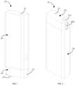
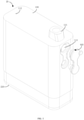
- an electronic atomization device 10 may be configured to atomize liquid represented by an aerosol-forming matrix.
- the electronic atomization device 10 includes an atomizer 20, a battery component 30 and a sensing component 500.
- the atomizer 20 and the battery component 30 may realize a detachable connection.
- the atomizer 20 includes an atomization mechanism 21 and an on-off component 300.
- the atomization mechanism 21 includes a housing 100 and an atomization component 200.
- the electronic atomization device 10 has a liquid suction chamber 104 and a liquid storage chamber 103.
- the liquid storage chamber 103 is configured to store liquid.
- the housing 100 is provided with a liquid outlet channel 106 communicated with the liquid storage chamber 103.
- the liquid storage chamber 103 may inject liquid into the liquid suction chamber 104 through the liquid outlet channel 106.
- the atomization component 200 is configured to atomize the liquid in the liquid suction chamber 104.
- the on-off component 300 is connected to the housing 100 and has a first station 11 and a second station 12.
- the on-off component 300 blocks the liquid outlet channel 106, the liquid storage chamber 103 and the liquid suction chamber 104 are isolated from each other, the liquid storage chamber 103 stops supplying liquid to the liquid suction chamber 104, and the sensing component 500 stops controlling the battery component 30 to heat the atomization component 200 to atomize the liquid in the liquid suction chamber 104, so that a user cannot suck the electronic atomization device 10.
- the on-off component 300 When the on-off component 300 is located at the second station 12, the on-off component 300 opens the liquid outlet channel 106, the liquid storage chamber 103 and the liquid suction chamber 104 are communicated with each other, the liquid storage chamber 103 can supply liquid to the liquid suction chamber 104, and the sensing component 500 controls the battery component 30 to heat the atomization component 200 to atomize the liquid in the liquid suction chamber 104, so that the user can suck the electronic atomization device 10.
- the liquid suction chamber 104 may not be provided, and the liquid in the liquid storage chamber 103 is directly supplied to the atomization component 200 through the liquid outlet channel 106. That is, the atomization component 200 sucks liquid directly from an end opening of the liquid outlet channel 106 through capillary action and atomizes the liquid.
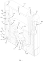
- the housing 100 includes a body portion 110, an isolation portion 120 and a nozzle portion 130.
- the body portion 110 defines a large accommodating chamber.
- the body portion 110 is roughly shaped like a cuboid with an opening.
- the isolation portion 120 is connected to the body portion 110 and located in the accommodating chamber.
- the isolation portion 120 and the body portion 110 define a first chamber 101 and a second chamber 102. That is, the isolation portion 120 separates the accommodating chamber into the first chamber 101 and the second chamber 102.
- the nozzle portion 130 is substantially in a shape of a tube.
- the nozzle portion 130 is connected to the body portion 110.
- a part of the nozzle portion 130 protrudes a set length from an outer surface of the body portion 110.
- the part of the nozzle portion 130 protruding from the outer surface of the body portion 110 forms a nozzle 131 for a user to suck.
- the other part of the nozzle portion 130 is located in the first chamber 101.
- the part of the nozzle portion 130 located in the first chamber 101 may be inserted into the atomization component 200.
- the atomization component 200 includes an atomizing core 210, a base 220, a top cover 230 and a sealing sleeve 240.
- the top cover 230 is provided with a cavity. A part of the base 220 is inserted into the cavity, and the other part of the base 220 is located outside the cavity and can close an opening of the cavity. At the same time, the other part of the base 220 can also close an opening of the accommodating chamber enclosed by the body portion 110.
- the atomizing core 210 is entirely located in the cavity of the top cover 230, and is interposed between the top cover 230 and the base 220.
- the atomizing core 210 and the top cover 230 jointly define the liquid suction chamber 104. That is, the atomizing core 210 can define a partial boundary of the liquid suction chamber 104.
- the base 220 is provided with a first step surface 221
- the top cover 230 is provided with a second step surface 231 arranged opposite to the first step surface 221
- the atomizing core 210 is sandwiched between the first step surface 221 and the second step surface 231.
- the mounting accuracy and efficiency of the atomizing core 210 can be improved by a limiting effect of the first step surface 221 and the second step surface 231 on the atomizing core 210.
- the top cover 230 is received in the first chamber 101.
- a remaining part of the first chamber 101 except a space for receiving the top cover 230 forms the liquid storage chamber 103. That is, the top cover 230, the isolation portion 120 and the body portion 110 jointly define the liquid storage chamber 103.
- the atomizer 20 further includes a cap 400.
- the body portion 110 is provided with a liquid injection hole 113 at a position close to the nozzle portion 130.
- the liquid injection hole 113 can communicate the outside with the liquid storage chamber 103.
- an amount of liquid stored in the liquid storage chamber 103 is lower than a set value, the liquid may be injected into the liquid storage chamber 103 through the liquid injection hole 113, so as to replenish an oil storage volume of the liquid storage chamber 103.
- the cap 400 is mounted on the body portion 110.
- the cap 400 is also engaged with the liquid injection hole 113 to block the liquid injection hole 113, so as to prevent leakage of the liquid from the liquid injection hole 113 and also prevent incursion of dust and other impurities into the liquid in the liquid storage chamber 103 through the liquid injection hole 113.
- a first airflow channel 201 is provided on the top cover 230 and the base 220, and the nozzle portion 130 of the housing 100 is provided with a second airflow channel 132.
- the nozzle portion 130 is inserted into an opening of the first airflow channel 201 in the top cover 230, so as to realize mutual communication between the first airflow channel 201 and the second airflow channel 132.
- the body portion 110 is provided with an air inlet 111 communicating the outside with the second chamber 102.
- the isolation portion 120 is provided with an air vent 123 communicating the first airflow channel 201 with the second chamber 102.
- the air inlet 111, the second chamber 102, the air vent 123, the first airflow channel 201 and the second airflow channel 132 jointly form a suction channel 105 for air circulation.
- an external airflow sequentially passes through the air inlet 111, the second chamber 102, the air vent 123, the first airflow channel 201 and the second airflow channel 132 so as to be sucked by the user (the dotted arrows in FIG. 6 indicate a flow direction of the airflow).
- the atomizing core 210 may be made of a porous ceramic material, and the atomizing core 210 is connected to the battery component 30 through an electrode.
- the atomizing core 210 has an atomizing surface 211.
- the first airflow channel 201 flows through the atomizing surface 211.
- the liquid in the liquid suction chamber 104 is sucked to the atomizing surface 211, the battery component 30 is heated to the atomizing surface 211 through the electrode, and the liquid is atomized on the atomizing surface 211 to form smoke.
- air entering from the air inlet 111, the second chamber 102 and the air vent 123 into the first airflow channel 201 carries the smoke and is sucked by the user through the second airflow channel 132.
- the sealing sleeve 240 may be a silicon gel sleeve or the like. That is, the sealing sleeve 240 is made of a silicon gel material.
- the atomizing core 210 is sleeved with the silicon gel sleeve and the silicon gel sleeve abuts between the first step surface 221 and the second step surface 231.
- the silicon gel sleeve may prevent leakage of the liquid in the liquid suction chamber 104 from gaps between the atomizing core 210 and the top cover 230 and between the atomizing core 210 and the base 220.
- the silicon gel sleeve may protect the atomizing core 210 and insulate heat, prevent the transfer of heat from the atomizing core 210 to the body portion 110 of the housing 100, so as to improve the utilization rate of energy, and at the same time, prevent the discomfort of the user due to the heat transferred to the body portion 110.
- the atomizing core 210 defines a surface of the boundary of the liquid suction chamber 104 to be recessed toward the atomizing surface 211 to form a buffer chamber 212.
- the buffer chamber 212 is communicated with the liquid suction chamber 104.
- the buffer chamber 212 may be configured to buffer the liquid in the liquid suction chamber 104. Due to the arrangement of the buffer chamber 212, a bottom wall of the buffer chamber 212 is relatively closer to the atomizing surface 211, so that the liquid can be transported to the atomizing surface 211 more quickly, so as to ensure that the atomizing surface 211 contains sufficient liquid and prevent dry burning due to insufficient liquid suction.
- a size a of a cross section of the buffer chamber 212 decreases along a direction of the liquid suction chamber 104 pointing to the first airflow channel 201, that is, a top-down direction, which may play a role in reasonably balancing liquid suction, so that the atomizing surface 211 can suck an appropriate amount of liquid, and prevent the leakage caused by too much liquid and dry burning caused by insufficient liquid on the atomizing surface 211.
- a first through hole 121 and a second through hole 122 are spaced apart on the isolation portion 120.
- the first through hole 121 and the second through hole 122 jointly form the liquid outlet channel 106.
- the first through hole 121 communicates the liquid storage chamber 103 with the second chamber 102.
- the second through hole 122 communicates the liquid suction chamber 104 with the second chamber 102.
- the second chamber 102 may be a cylindrical chamber.
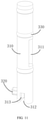
- the on-off component 300 includes a slide bar 310, a sealing member 330 and a handle 320.
- the slide bar 310 is slidably arranged in the second chamber 102.
- An outer surface of the slide bar 310 is radially recessed to form a communicating chamber 311.
- the outer surface of the slide bar 310 can effectively block the first through hole 121 on the isolation portion 120, so as to block the entire liquid outlet channel 106 and prevent the liquid in the liquid storage chamber 103 from flowing out of the first through hole 121.
- the liquid in the liquid storage chamber 103 cannot enter the liquid suction chamber 104.
- the second through hole 122 is also communicated with the communicating chamber 311.
- the liquid in the liquid storage chamber 103 can enter the liquid suction chamber 104 successively through the first through hole 121, the cavity communicating chamber 311 and the second through hole 122 (the solid arrows in FIG. 6 indicate a flow direction of the liquid).
- the sealing member 330 may be an O-ring or the like.
- the sealing member 330 is embedded into the slide bar 310 and capable of abutting between the slide bar 310 and an inner wall of the second chamber 102, to prevent leakage of liquid and air from a gap between the slide bar 310 and the inner wall of the second chamber 102.
- the handle 320 is connected to the slide bar 310. The user may apply a force to the handle 320, so as to drive the slide bar 310 to slide up and down in the second chamber 102.
- the handle 320 passes through the air inlet 111.
- the air inlet 111 provides an avoidance space for motion of the handle 320.
- the slide bar 310 may block the air inlet 111 completely.
- the on-off component 300 may be in other shapes, and the on-off component 300 is rotatably arranged in the second chamber 102.
- the handle 320 may also be omitted.
- the slide bar 310 is pushed through an automatic control mechanism to slide in the second chamber 102.
- the body portion 110 is further provided with an air outlet 112.
- the air outlet 112 corresponds to an end portion of the second chamber 102.
- the air outlet 112 and the second chamber 102 are communicated with each other.
- a volume of an upper part of the second chamber 102 is reduced, and the air in an upper space of the second chamber 102 may be discharged from the air outlet 112 to prevent hindrance of pressure generated by compressed air to the sliding of the slide bar 310 and ensure the smooth pushing of the slide bar 310.
- the slide bar 310 When the slide bar 310 is located at the first station 11, the slide bar 310 prevents the sensing component 500 from sensing negative pressure in the suction channel 105 to control the battery component 30 to stop heating the atomizing core 210, thereby preventing atomization of the liquid.
- the slide bar 310 When the slide bar 310 is located at the second station 12, the slide bar 310 enables the sensing component 500 to sense the negative pressure in the suction channel 105 to control the battery component 30 to heat the atomizing core 210, thereby starting the atomization of the liquid.
- the sensing component 500 includes an airflow sensor 510.
- the airflow sensor 510 may be directly arranged on the battery component 30 or directly arranged on the atomization component 200.
- the atomization component 200 is provided with a sensing channel 513.
- the sensing channel 513 can be communicated with the suction channel 105.
- the negative pressure generated due to suction in the suction channel 105 can be sensed by the sensing component 500 through the sensing channel 513.
- the slide bar 310 closes the sensing channel 513 to hinder the sensing channel 513 from communicating with the suction channel 105.
- the slide bar 310 stops closing the sensing channel 513 to enable the sensing channel 513 to communicate with the suction channel 105.
- the slide bar 310 is provided with a jack 312.
- the jack 312 may be a cylindrical hole.
- the base 200 of the atomization component 200 is provided with an insertion portion 511.
- the sensing channel 513 is provided on the insertion portion 511.
- the insertion portion 511 matches the jack 312 in shape, so that the insertion portion 511 can be inserted into the jack 312.
- a communicating port 513a communicated with the sensing channel 513 and the suction channel 105 is formed at a top end surface of the insertion portion 511.
- the insertion portion 511 is inserted into the jack 312, and a bottom wall of the jack 312 blocks the communicating port 513a, so as to block the communication between the sensing channel 513 and the suction channel 105.
- the airflow sensor 510 cannot sense the negative pressure through the sensing channel 513, so that the airflow sensor 510 cannot control the battery component 30 to heat the atomizing core 210 to atomize the liquid, and the electronic atomization device 10 cannot be turned on. As a result, the user cannot suck.
- the slide bar 310 may completely block the air inlet 111 at the first station 11, an external airflow cannot enter the suction channel 105, which can also prevent the user from suction.
- the insertion portion 511 may be completely detached from the jack 312, the slide bar 310 removes the blocking of the communicating port 513a and the air inlet 111, and the sensing channel 513 is communicated with the suction channel 105.
- the airflow sensor 510 senses the negative pressure in the suction channel 105 through the sensing channel 513, so as to control the battery component 30 to heat the atomizing core 210 to atomize the liquid.
- the smoke formed by the atomization of the liquid along with the airflow in the suction channel 105 may be sucked by the user, and the electronic atomization device 10 may be turned on to realize a suction function.
- the airflow sensor 510 senses the negative pressure in the suction channel 105 to control the electronic atomization device 10 to be turned on, which enables the electronic atomization device 10 to be sucked quickly and improves the sensitivity of the turn-on of the electronic atomization device 10.
- the slide bar 310 may be further provided with a guide groove 313.
- the guide groove 313 extends a set length along an axial direction of the slide bar 310.
- the guide groove 313 can be communicated with the jack 312 and the suction channel 105.
- the insertion portion 511 is provided with a guide piece 512.
- the guide piece 512 is substantially in a shape of a rectangle.
- the guide piece 512 engages with the guide groove 313. During the downward movement of the slide bar 310 from the second station 12 to the first station 11, the insertion portion 511 can smoothly engage with the jack 312 under guidance of the guide piece 512.
- the bottom wall of the jack 312 releases the closure of the communicating port 513a, so that the airflow sensor 510 can quickly and accurately sense the negative pressure in the suction channel 105 through the sensing channel 513 and the guide groove 313, which further improves the sensitivity of the electronic atomization device 10 to a suction response and ensures rapid turn-on of the electronic atomization device 10.
- the battery component 30 is provided with a charging interface 31.
- the charging interface 31 is arranged on an end portion of the battery component 30 away from the atomizer 20, that is, a bottom portion of the battery component 30. The arrangement of the charging interface 31 enables the battery component 30 to be charged at any time.
- the handle 320 When the electronic atomization device 10 is required to be turned on for suction, firstly, the handle 320 is pushed to drive the slide bar 310 to move to the second station 12. In this case, the liquid in the liquid storage chamber 103 enters the liquid suction chamber 104 sequentially through the first through hole 121, the communicating chamber 311 and the second through hole 122. Moreover, the insertion portion 511 is detached from the jack 312 in the slide bar 310, and the sensing channel 513 is communicated with the suction channel 105. Then, the user sucks at the nozzle 131, so that negative pressure is generated in the suction channel 105. The airflow sensor 510 senses the negative pressure through the sensing channel 513 and controls the battery component 30 to heat the atomizing core 210, so as to atomize the liquid for suction.
- the handle 320 may be pushed to drive the slide bar 310 to the first station 11.
- the slide bar 310 blocks the first through hole 121, and the liquid in the liquid storage chamber 103 cannot flow out of the first through hole 121, so that the liquid in the liquid storage chamber 103 cannot enter the liquid suction chamber 104.
- the insertion portion 511 is inserted into the jack 312 in the slide bar 310, and the slide bar 310 blocks the communicating portion 513a on the insertion portion 511 to hinder the sensing channel 513 from communicating with the suction channel 105.
- the airflow sensor 510 cannot sense the negative pressure through the sensing channel 513 to control the battery component 30 to heat the atomizing core 210, so that the liquid cannot be atomized for suction.
- the slide bar 310 may also block the air inlet 111 completely, further preventing the user from suction.
- the slide bar 310 may be located at the first station 11, so that the liquid storage chamber 103 and the liquid suction chamber 104 are isolated from each other, and there may be no large amount of liquid in the liquid suction chamber 104, so as to effectively prevent leakage of the liquid in the liquid suction chamber 104 from the atomizing core 210.
- the airflow sensor 510 senses the negative pressure in the suction channel 105 to control the electronic atomization device 10 to be turned on rapidly, which improves the sensitivity of the turn-on of the electronic atomization device 10.
Landscapes
- Engineering & Computer Science (AREA)
- Human Computer Interaction (AREA)
- Special Spraying Apparatus (AREA)
- Disinfection, Sterilisation Or Deodorisation Of Air (AREA)
- Containers And Packaging Bodies Having A Special Means To Remove Contents (AREA)
Applications Claiming Priority (1)
| Application Number | Priority Date | Filing Date | Title |
|---|---|---|---|
| PCT/CN2019/086741 WO2020227910A1 (zh) | 2019-05-14 | 2019-05-14 | 雾化器及电子雾化装置 |
Publications (3)
| Publication Number | Publication Date |
|---|---|
| EP3970533A1 true EP3970533A1 (de) | 2022-03-23 |
| EP3970533A4 EP3970533A4 (de) | 2022-12-21 |
| EP3970533B1 EP3970533B1 (de) | 2025-10-08 |
Family
ID=73289774
Family Applications (1)
| Application Number | Title | Priority Date | Filing Date |
|---|---|---|---|
| EP19928583.4A Active EP3970533B1 (de) | 2019-05-14 | 2019-05-14 | Zerstäuber und elektronische zerstäubungsvorrichtung |
Country Status (4)
| Country | Link |
|---|---|
| US (2) | US12219998B2 (de) |
| EP (1) | EP3970533B1 (de) |
| JP (1) | JP7291249B2 (de) |
| WO (1) | WO2020227910A1 (de) |
Cited By (1)
| Publication number | Priority date | Publication date | Assignee | Title |
|---|---|---|---|---|
| EP4529781A1 (de) * | 2023-09-29 | 2025-04-02 | Imperial Tobacco Limited | Aerosolerzeugungsvorrichtung |
Families Citing this family (13)
| Publication number | Priority date | Publication date | Assignee | Title |
|---|---|---|---|---|
| EP3970533B1 (de) * | 2019-05-14 | 2025-10-08 | Shenzhen Smoore Technology Limited | Zerstäuber und elektronische zerstäubungsvorrichtung |
| CN111772240B (zh) * | 2020-06-15 | 2024-12-17 | 深圳麦克韦尔科技有限公司 | 雾化器及其储液组件、电子雾化装置 |
| EP4026433B1 (de) * | 2020-07-24 | 2024-04-17 | Shenzhen Huachengda Precision Industry Co., Ltd. | Kapillarflüssigkeitsleitende zerstäubungseinheit und zerstäubungsvorrichtung |
| US11992054B2 (en) * | 2020-12-04 | 2024-05-28 | Aspire North America Llc | Atomizer comprising bowl-shaped ceramic core |
| CN114794548B (zh) * | 2021-01-27 | 2025-07-29 | 深圳市合元科技有限公司 | 雾化芯组件、雾化器和电子雾化装置 |
| CN115363253A (zh) * | 2021-05-21 | 2022-11-22 | 深圳市卓力能技术有限公司 | 雾化器及应用该雾化器的电子雾化设备 |
| CN115363254A (zh) * | 2021-05-21 | 2022-11-22 | 深圳市卓力能技术有限公司 | 一种雾化器及电子雾化设备 |
| WO2023019440A1 (zh) * | 2021-08-17 | 2023-02-23 | 深圳麦克韦尔科技有限公司 | 雾化器及电子雾化装置 |
| WO2023019572A1 (zh) * | 2021-08-20 | 2023-02-23 | 深圳麦克韦尔科技有限公司 | 一种电子雾化装置及其雾化器 |
| CN116264915A (zh) * | 2021-12-19 | 2023-06-20 | 比亚迪精密制造有限公司 | 雾化装置和具有其的电子烟 |
| CN116998768A (zh) * | 2022-04-29 | 2023-11-07 | 海南摩尔兄弟科技有限公司 | 电子雾化装置及其储液雾化组件和喷嘴 |
| CN115530448A (zh) * | 2022-11-02 | 2022-12-30 | 深圳市你我网络科技有限公司 | 电子雾化装置 |
| CN117918593A (zh) * | 2024-03-07 | 2024-04-26 | 深圳市吉迩科技有限公司 | 雾化器及其装配方法和气溶胶发生装置 |
Family Cites Families (39)
| Publication number | Priority date | Publication date | Assignee | Title |
|---|---|---|---|---|
| US3661323A (en) * | 1970-06-10 | 1972-05-09 | Richard W Farris | Odor neutralizing device |
| US6706988B1 (en) * | 2002-11-08 | 2004-03-16 | S. C. Johnson & Son, Inc. | Switch actuating mechanism and electrically controlled device using same |
| JP2007029771A (ja) | 2005-07-22 | 2007-02-08 | Mikuni Corp | 噴霧装置 |
| US7455245B2 (en) * | 2006-07-14 | 2008-11-25 | S.C. Johnson & Son, Inc. | Diffusion device |
| ITBS20090030U1 (it) * | 2009-10-15 | 2011-04-16 | Flaem Nuova Spa | Ampolla a due velocità di erogazione per apparecchi per aerosolterapia |
| US8578942B2 (en) * | 2010-05-25 | 2013-11-12 | British American Tobacco (Investments) Limited | Aerosol generator |
| US8950395B2 (en) * | 2010-05-25 | 2015-02-10 | Nicoventures Holdings Limited | Aerosol generator |
| UA111630C2 (uk) | 2011-10-06 | 2016-05-25 | Сіс Рісорсез Лтд. | Система для паління |
| WO2014040217A1 (zh) * | 2012-09-11 | 2014-03-20 | Liu Qiuming | 电子烟及其电子烟装置 |
| US20140174458A1 (en) * | 2012-12-21 | 2014-06-26 | Samuel Aaron Katz | Self-contained electronic smoking device that produces smoke and ash by incineration |
| US10279934B2 (en) * | 2013-03-15 | 2019-05-07 | Juul Labs, Inc. | Fillable vaporizer cartridge and method of filling |
| CN103932401B (zh) * | 2013-09-29 | 2015-09-30 | 深圳麦克韦尔股份有限公司 | 电子烟 |
| US9440035B2 (en) * | 2013-10-02 | 2016-09-13 | Henry Chung | Vapor inhaler |
| KR101454125B1 (ko) | 2013-10-08 | 2014-10-27 | 박선순 | 집적형 전자 담배 |
| US10039321B2 (en) * | 2013-11-12 | 2018-08-07 | Vmr Products Llc | Vaporizer |
| US20150216234A1 (en) * | 2014-02-06 | 2015-08-06 | Esquire Properties Trading Inc. | Electronic cigarette |
| US20170196265A1 (en) | 2014-05-28 | 2017-07-13 | Kimree Hi-Tech Inc. | Electronic cigarette and air intake volume regulating method for electronic cigarette |
| GB2528712B (en) | 2014-07-29 | 2019-03-27 | Nicoventures Holdings Ltd | E-cigarette and re-charging pack |
| CN204232296U (zh) | 2014-10-24 | 2015-04-01 | 深圳市合元科技有限公司 | 烟碱液雾化器及包括该烟碱液雾化器的吸烟装置 |
| CN104544570B (zh) | 2014-12-31 | 2017-12-08 | 深圳麦克韦尔股份有限公司 | 吸入器及其雾化组件 |
| CN104839893B (zh) | 2015-04-28 | 2018-06-26 | 深圳麦克韦尔股份有限公司 | 吸入器及其雾化组件 |
| CN105212278B (zh) | 2015-10-28 | 2019-03-22 | 深圳麦克韦尔股份有限公司 | 电子烟雾化器 |
| CN208798692U (zh) | 2018-05-31 | 2019-04-30 | 卓尔悦欧洲控股有限公司 | 雾化器及电子烟 |
| WO2018039876A1 (zh) | 2016-08-29 | 2018-03-08 | 惠州市吉瑞科技有限公司深圳分公司 | 一种烟油瓶以及电子烟雾化器 |
| CN106723379B (zh) | 2017-01-16 | 2023-07-28 | 常州市派腾电子技术服务有限公司 | 电子烟 |
| TWI640257B (zh) | 2017-04-11 | 2018-11-11 | 研能科技股份有限公司 | 電子香煙 |
| EP3597057B1 (de) | 2017-04-13 | 2022-01-05 | China Tobacco Hunan Industrial Co., Ltd. | Zerstäuber und elektronische zigarette damit |
| WO2018188231A1 (zh) * | 2017-04-14 | 2018-10-18 | 常州市派腾电子技术服务有限公司 | 加热装置、雾化器及电子烟 |
| CN207940347U (zh) | 2018-01-02 | 2018-10-09 | 上海新型烟草制品研究院有限公司 | 一种雾化器及电子烟 |
| CN108308715B (zh) | 2018-02-13 | 2020-09-15 | 深圳麦克韦尔科技有限公司 | 电子烟及其发热组件和发热体 |
| CN108576941B (zh) | 2018-07-17 | 2021-07-16 | 深圳市劲嘉科技有限公司 | 一种电子烟及其雾化器 |
| CN209420955U (zh) * | 2018-11-14 | 2019-09-24 | 常州市派腾电子技术服务有限公司 | 一种电子烟 |
| CN109480338B (zh) | 2018-12-18 | 2024-06-18 | 深圳市你我网络科技有限公司 | 一种雾化器及使用该雾化器的电子烟 |
| CN109619700B (zh) | 2019-01-31 | 2021-10-22 | 常州市派腾电子技术服务有限公司 | 电子烟的烟弹、注液方法、控制方法及电子烟 |
| EP3970533B1 (de) * | 2019-05-14 | 2025-10-08 | Shenzhen Smoore Technology Limited | Zerstäuber und elektronische zerstäubungsvorrichtung |
| CN110101121B (zh) | 2019-05-14 | 2024-09-27 | 深圳麦克韦尔科技有限公司 | 雾化器及电子雾化装置 |
| CN110101120B (zh) | 2019-05-14 | 2024-08-23 | 深圳麦克韦尔科技有限公司 | 雾化器及电子雾化装置 |
| CN210492612U (zh) | 2019-05-14 | 2020-05-12 | 深圳麦克韦尔科技有限公司 | 雾化器及电子雾化装置 |
| CN210841569U (zh) | 2019-05-14 | 2020-06-26 | 深圳麦克韦尔科技有限公司 | 雾化器及电子雾化装置 |
-
2019
- 2019-05-14 EP EP19928583.4A patent/EP3970533B1/de active Active
- 2019-05-14 US US17/609,046 patent/US12219998B2/en active Active
- 2019-05-14 JP JP2021567968A patent/JP7291249B2/ja active Active
- 2019-05-14 WO PCT/CN2019/086741 patent/WO2020227910A1/zh not_active Ceased
-
2024
- 2024-12-24 US US19/001,015 patent/US20250204600A1/en active Pending
Cited By (2)
| Publication number | Priority date | Publication date | Assignee | Title |
|---|---|---|---|---|
| EP4529781A1 (de) * | 2023-09-29 | 2025-04-02 | Imperial Tobacco Limited | Aerosolerzeugungsvorrichtung |
| WO2025068250A1 (en) * | 2023-09-29 | 2025-04-03 | Imperial Tobacco Limited | Aerosol-generating apparatus |
Also Published As
| Publication number | Publication date |
|---|---|
| EP3970533B1 (de) | 2025-10-08 |
| US20220192271A1 (en) | 2022-06-23 |
| US12219998B2 (en) | 2025-02-11 |
| JP7291249B2 (ja) | 2023-06-14 |
| EP3970533A4 (de) | 2022-12-21 |
| US20250204600A1 (en) | 2025-06-26 |
| JP2022532613A (ja) | 2022-07-15 |
| WO2020227910A1 (zh) | 2020-11-19 |
Similar Documents
| Publication | Publication Date | Title |
|---|---|---|
| US20250204600A1 (en) | Atomizer and electronic atomization device | |
| CN110101120B (zh) | 雾化器及电子雾化装置 | |
| CN210841569U (zh) | 雾化器及电子雾化装置 | |
| CN110101121B (zh) | 雾化器及电子雾化装置 | |
| CN210492612U (zh) | 雾化器及电子雾化装置 | |
| US12322764B2 (en) | Cartridge, battery assembly and electronic cigarette | |
| US20190297952A1 (en) | Cartridge, atomizing assembly and electronic cigarette thereof | |
| WO2017173951A1 (zh) | 烟弹及带有该烟弹的电子烟 | |
| EP3890523B1 (de) | Zerstäuberauswurfmechanismus für einen aerosolinhalator | |
| WO2017071297A1 (zh) | 烟油瓶及电子烟 | |
| US11000067B1 (en) | Portable electronic vaporizing device | |
| CN111904038A (zh) | 烟弹及其电子烟 | |
| CN108024581A (zh) | 具有远程进气口的气溶胶提供系统 | |
| CN105764362B (zh) | 雾化装置、电子烟及调节烟油出油量的方法 | |
| WO2018113278A1 (zh) | 上盖组件、雾化装置及电子烟 | |
| KR20210100405A (ko) | 에어로졸 공급 장치 및 이를 구비한 에어로졸 생성 장치 | |
| CN215531621U (zh) | 雾化器及电子雾化装置 | |
| CN113197351A (zh) | 一种雾化器和电子雾化装置 | |
| CN217184835U (zh) | 雾化器及气溶胶发生装置 | |
| CN113197352B (zh) | 一种电子雾化装置 | |
| CN216701644U (zh) | 雾化器及气溶胶发生装置 | |
| WO2019014886A1 (zh) | 一种雾化器 | |
| CN110742313B (zh) | 雾化器及电子雾化装置 | |
| CN211091863U (zh) | 电子烟及其雾化器 | |
| CN217364668U (zh) | 一种电子雾化装置 |
Legal Events
| Date | Code | Title | Description |
|---|---|---|---|
| STAA | Information on the status of an ep patent application or granted ep patent |
Free format text: STATUS: THE INTERNATIONAL PUBLICATION HAS BEEN MADE |
|
| PUAI | Public reference made under article 153(3) epc to a published international application that has entered the european phase |
Free format text: ORIGINAL CODE: 0009012 |
|
| STAA | Information on the status of an ep patent application or granted ep patent |
Free format text: STATUS: REQUEST FOR EXAMINATION WAS MADE |
|
| 17P | Request for examination filed |
Effective date: 20211207 |
|
| AK | Designated contracting states |
Kind code of ref document: A1 Designated state(s): AL AT BE BG CH CY CZ DE DK EE ES FI FR GB GR HR HU IE IS IT LI LT LU LV MC MK MT NL NO PL PT RO RS SE SI SK SM TR |
|
| DAV | Request for validation of the european patent (deleted) | ||
| DAX | Request for extension of the european patent (deleted) | ||
| A4 | Supplementary search report drawn up and despatched |
Effective date: 20221116 |
|
| RIC1 | Information provided on ipc code assigned before grant |
Ipc: A24F 40/40 20200101ALI20221111BHEP Ipc: A24F 40/10 20200101ALI20221111BHEP Ipc: A24F 40/485 20200101AFI20221111BHEP |
|
| STAA | Information on the status of an ep patent application or granted ep patent |
Free format text: STATUS: EXAMINATION IS IN PROGRESS |
|
| 17Q | First examination report despatched |
Effective date: 20240418 |
|
| RAP3 | Party data changed (applicant data changed or rights of an application transferred) |
Owner name: SHENZHEN SMOORE TECHNOLOGY LIMITED |
|
| GRAP | Despatch of communication of intention to grant a patent |
Free format text: ORIGINAL CODE: EPIDOSNIGR1 |
|
| STAA | Information on the status of an ep patent application or granted ep patent |
Free format text: STATUS: GRANT OF PATENT IS INTENDED |
|
| RAP3 | Party data changed (applicant data changed or rights of an application transferred) |
Owner name: SHENZHEN SMOORE TECHNOLOGY LIMITED |
|
| INTG | Intention to grant announced |
Effective date: 20250520 |
|
| GRAS | Grant fee paid |
Free format text: ORIGINAL CODE: EPIDOSNIGR3 |
|
| GRAA | (expected) grant |
Free format text: ORIGINAL CODE: 0009210 |
|
| STAA | Information on the status of an ep patent application or granted ep patent |
Free format text: STATUS: THE PATENT HAS BEEN GRANTED |
|
| P01 | Opt-out of the competence of the unified patent court (upc) registered |
Free format text: CASE NUMBER: UPC_APP_2270_3970533/2025 Effective date: 20250804 |
|
| AK | Designated contracting states |
Kind code of ref document: B1 Designated state(s): AL AT BE BG CH CY CZ DE DK EE ES FI FR GB GR HR HU IE IS IT LI LT LU LV MC MK MT NL NO PL PT RO RS SE SI SK SM TR |
|
| REG | Reference to a national code |
Ref country code: GB Ref legal event code: FG4D Ref country code: CH Ref legal event code: F10 Free format text: ST27 STATUS EVENT CODE: U-0-0-F10-F00 (AS PROVIDED BY THE NATIONAL OFFICE) Effective date: 20251008 |
|
| REG | Reference to a national code |
Ref country code: DE Ref legal event code: R096 Ref document number: 602019076763 Country of ref document: DE |
|
| REG | Reference to a national code |
Ref country code: IE Ref legal event code: FG4D |
|
| REG | Reference to a national code |
Ref country code: NL Ref legal event code: MP Effective date: 20251008 |
|
| REG | Reference to a national code |
Ref country code: AT Ref legal event code: MK05 Ref document number: 1844103 Country of ref document: AT Kind code of ref document: T Effective date: 20251008 |
|
| PG25 | Lapsed in a contracting state [announced via postgrant information from national office to epo] |
Ref country code: NL Free format text: LAPSE BECAUSE OF FAILURE TO SUBMIT A TRANSLATION OF THE DESCRIPTION OR TO PAY THE FEE WITHIN THE PRESCRIBED TIME-LIMIT Effective date: 20251008 |
|
| PG25 | Lapsed in a contracting state [announced via postgrant information from national office to epo] |
Ref country code: ES Free format text: LAPSE BECAUSE OF FAILURE TO SUBMIT A TRANSLATION OF THE DESCRIPTION OR TO PAY THE FEE WITHIN THE PRESCRIBED TIME-LIMIT Effective date: 20251008 |
|
| REG | Reference to a national code |
Ref country code: LT Ref legal event code: MG9D |
|
| PG25 | Lapsed in a contracting state [announced via postgrant information from national office to epo] |
Ref country code: NO Free format text: LAPSE BECAUSE OF FAILURE TO SUBMIT A TRANSLATION OF THE DESCRIPTION OR TO PAY THE FEE WITHIN THE PRESCRIBED TIME-LIMIT Effective date: 20260108 |
|
| PG25 | Lapsed in a contracting state [announced via postgrant information from national office to epo] |
Ref country code: AT Free format text: LAPSE BECAUSE OF FAILURE TO SUBMIT A TRANSLATION OF THE DESCRIPTION OR TO PAY THE FEE WITHIN THE PRESCRIBED TIME-LIMIT Effective date: 20251008 Ref country code: HR Free format text: LAPSE BECAUSE OF FAILURE TO SUBMIT A TRANSLATION OF THE DESCRIPTION OR TO PAY THE FEE WITHIN THE PRESCRIBED TIME-LIMIT Effective date: 20251008 Ref country code: FI Free format text: LAPSE BECAUSE OF FAILURE TO SUBMIT A TRANSLATION OF THE DESCRIPTION OR TO PAY THE FEE WITHIN THE PRESCRIBED TIME-LIMIT Effective date: 20251008 |
|
| PG25 | Lapsed in a contracting state [announced via postgrant information from national office to epo] |
Ref country code: RS Free format text: LAPSE BECAUSE OF FAILURE TO SUBMIT A TRANSLATION OF THE DESCRIPTION OR TO PAY THE FEE WITHIN THE PRESCRIBED TIME-LIMIT Effective date: 20260108 |
|
| PG25 | Lapsed in a contracting state [announced via postgrant information from national office to epo] |
Ref country code: IS Free format text: LAPSE BECAUSE OF FAILURE TO SUBMIT A TRANSLATION OF THE DESCRIPTION OR TO PAY THE FEE WITHIN THE PRESCRIBED TIME-LIMIT Effective date: 20260208 |
|
| PG25 | Lapsed in a contracting state [announced via postgrant information from national office to epo] |
Ref country code: PT Free format text: LAPSE BECAUSE OF FAILURE TO SUBMIT A TRANSLATION OF THE DESCRIPTION OR TO PAY THE FEE WITHIN THE PRESCRIBED TIME-LIMIT Effective date: 20260209 |
|
| PG25 | Lapsed in a contracting state [announced via postgrant information from national office to epo] |
Ref country code: PL Free format text: LAPSE BECAUSE OF FAILURE TO SUBMIT A TRANSLATION OF THE DESCRIPTION OR TO PAY THE FEE WITHIN THE PRESCRIBED TIME-LIMIT Effective date: 20251008 |
|
| PG25 | Lapsed in a contracting state [announced via postgrant information from national office to epo] |
Ref country code: LV Free format text: LAPSE BECAUSE OF FAILURE TO SUBMIT A TRANSLATION OF THE DESCRIPTION OR TO PAY THE FEE WITHIN THE PRESCRIBED TIME-LIMIT Effective date: 20251008 |