EP3970470A1 - Mowing device - Google Patents
Mowing device Download PDFInfo
- Publication number
- EP3970470A1 EP3970470A1 EP21178738.7A EP21178738A EP3970470A1 EP 3970470 A1 EP3970470 A1 EP 3970470A1 EP 21178738 A EP21178738 A EP 21178738A EP 3970470 A1 EP3970470 A1 EP 3970470A1
- Authority
- EP
- European Patent Office
- Prior art keywords
- section
- motor
- output shaft
- mowing device
- cutting blade
- Prior art date
- Legal status (The legal status is an assumption and is not a legal conclusion. Google has not performed a legal analysis and makes no representation as to the accuracy of the status listed.)
- Pending
Links
Images


Classifications
-
- A—HUMAN NECESSITIES
- A01—AGRICULTURE; FORESTRY; ANIMAL HUSBANDRY; HUNTING; TRAPPING; FISHING
- A01D—HARVESTING; MOWING
- A01D34/00—Mowers; Mowing apparatus of harvesters
- A01D34/01—Mowers; Mowing apparatus of harvesters characterised by features relating to the type of cutting apparatus
- A01D34/412—Mowers; Mowing apparatus of harvesters characterised by features relating to the type of cutting apparatus having rotating cutters
- A01D34/63—Mowers; Mowing apparatus of harvesters characterised by features relating to the type of cutting apparatus having rotating cutters having cutters rotating about a vertical axis
- A01D34/81—Casings; Housings
-
- A—HUMAN NECESSITIES
- A01—AGRICULTURE; FORESTRY; ANIMAL HUSBANDRY; HUNTING; TRAPPING; FISHING
- A01D—HARVESTING; MOWING
- A01D34/00—Mowers; Mowing apparatus of harvesters
- A01D34/01—Mowers; Mowing apparatus of harvesters characterised by features relating to the type of cutting apparatus
- A01D34/412—Mowers; Mowing apparatus of harvesters characterised by features relating to the type of cutting apparatus having rotating cutters
- A01D34/63—Mowers; Mowing apparatus of harvesters characterised by features relating to the type of cutting apparatus having rotating cutters having cutters rotating about a vertical axis
- A01D34/64—Mowers; Mowing apparatus of harvesters characterised by features relating to the type of cutting apparatus having rotating cutters having cutters rotating about a vertical axis mounted on a vehicle, e.g. a tractor, or drawn by an animal or a vehicle
- A01D34/66—Mowers; Mowing apparatus of harvesters characterised by features relating to the type of cutting apparatus having rotating cutters having cutters rotating about a vertical axis mounted on a vehicle, e.g. a tractor, or drawn by an animal or a vehicle with two or more cutters
-
- A—HUMAN NECESSITIES
- A01—AGRICULTURE; FORESTRY; ANIMAL HUSBANDRY; HUNTING; TRAPPING; FISHING
- A01D—HARVESTING; MOWING
- A01D34/00—Mowers; Mowing apparatus of harvesters
- A01D34/01—Mowers; Mowing apparatus of harvesters characterised by features relating to the type of cutting apparatus
- A01D34/412—Mowers; Mowing apparatus of harvesters characterised by features relating to the type of cutting apparatus having rotating cutters
- A01D34/63—Mowers; Mowing apparatus of harvesters characterised by features relating to the type of cutting apparatus having rotating cutters having cutters rotating about a vertical axis
- A01D34/82—Other details
-
- A—HUMAN NECESSITIES
- A01—AGRICULTURE; FORESTRY; ANIMAL HUSBANDRY; HUNTING; TRAPPING; FISHING
- A01D—HARVESTING; MOWING
- A01D69/00—Driving mechanisms or parts thereof for harvesters or mowers
- A01D69/02—Driving mechanisms or parts thereof for harvesters or mowers electric
-
- A—HUMAN NECESSITIES
- A01—AGRICULTURE; FORESTRY; ANIMAL HUSBANDRY; HUNTING; TRAPPING; FISHING
- A01D—HARVESTING; MOWING
- A01D34/00—Mowers; Mowing apparatus of harvesters
- A01D34/01—Mowers; Mowing apparatus of harvesters characterised by features relating to the type of cutting apparatus
- A01D34/412—Mowers; Mowing apparatus of harvesters characterised by features relating to the type of cutting apparatus having rotating cutters
- A01D34/63—Mowers; Mowing apparatus of harvesters characterised by features relating to the type of cutting apparatus having rotating cutters having cutters rotating about a vertical axis
- A01D34/76—Driving mechanisms for the cutters
- A01D34/78—Driving mechanisms for the cutters electric
Definitions
- the present invention relates to a mowing device.
- a mowing device may include a cutting blade housing and cutting blades present inside the cutting blade housing and drivable to rotate.
- An example of such a mowing device is the mower unit disclosed in Patent Literature 1.
- the mower unit includes a "mower deck” as the cutting blade housing and "blades” as the cutting blades.
- a mowing device of this type may include, as disclosed in Patent Literature 1, an electric motor (“work motor” in Patent Literature 1) supported by the cutting blade housing and configured to drive the cutting blades.
- Patent Literature 1 Japanese Unexamined Patent Application Publication, Tokukai, No. 2019-17278
- the present invention has an object of providing an inexpensive mowing device configured to drive a cutting blade with use of an electric motor and yet capable of continuing mowing work over an extended period of time.
- a mowing device as an embodiment of the present invention includes: a cutting blade housing; a cutting blade present inside the cutting blade housing and drivable to rotate; and an electric motor supported by the cutting blade housing and configured to drive the cutting blade, wherein the electric motor includes: a motor section; and an output shaft protruding from the motor section, and the mowing device further includes a rotary fan supported by the output shaft and drivable by the output shaft to rotate to supply cooling air to the motor section.
- the above arrangement allows the rotary fan to be driven by the electric motor to supply cooling air to the motor section and cool the motor section. This prevents the electric motor from becoming heated up excessively, and thereby prevents the electric motor from becoming broken down.
- the above arrangement in other words, allows the mowing device to continue mowing work over an extended period of time. Further, the simple structure of the rotary fan being supported by the output shaft allows production of an inexpensive mowing device.
- a mowing device as a preferable embodiment of the present invention includes: a fan cover covering the rotary fan and having a vent hole, wherein the rotary fan supplies the cooling air to the motor section by taking in the cooling air from outside the fan cover through the vent hole, and the rotary fan includes a cutter section configured to cut a foreign object having entered the fan cover through the vent hole.
- the above arrangement allows the cutter section to cut a foreign object such as mown grass having entered the fan cover. Such a foreign object and/or the like is thus cut to shreds and easily discharged from the fan cover with use of, for example, cooling air.
- the above arrangement thereby prevents a foreign object and/or the like having entered the fan cover from remaining on, for example, the motor section to prevent the cooling effect from becoming decreased and more reliably prevent the electric motor from becoming heated up excessively.
- a mowing device as a preferable embodiment of the present invention is arranged such that the motor section includes a cooling fin section configured to dissipate heat of the motor section, and the cooling fin section receives the cooling air supplied by the rotary fan.
- the above arrangement allows heat of the motor section to be conducted to the cooling fin section and then dissipated by means of the cooling fin section.
- the above arrangement also promotes dissipation of heat from the cooling fin section due to cooling air that the rotary fan supplies to the cooling fin section.
- the above arrangement thereby cools the motor section effectively. This more reliably prevents the electric motor from becoming heated up excessively, and thereby effectively prevents the electric motor from becoming broken down.
- a mowing device as a preferable embodiment of the present invention is arranged such that the cooling fin section includes a plurality of linear fins present around the output shaft in a plan view.
- the above arrangement involves linear fins present over a wide area around the motor section in a plan view. This allows the electric motor to be cooled more effectively through heat dissipation by the cooling fin section.
- a mowing device as a preferable embodiment of the present invention is arranged such that the plurality of linear fins extend radially from the output shaft.
- the above arrangement allows cooling air supplied by the rotary fan to the cooling fin section to flow along the plurality of linear fins from the output shaft side to the opposite side. This promotes heat dissipation by the cooling fin section, and thereby allows the electric motor to be cooled more effectively.
- a mowing device as a preferable embodiment of the present invention includes: an output pulley which is present on the output shaft and between the rotary fan and the motor section and around which a power transmission belt is wound, the power transmission belt interlocking the output shaft and the cutting blade with each other.
- the above arrangement allows cooling air supplied from the rotary fan toward the motor section to be brought to the output pulley, meaning that the rotary fan is usable also as a means of cooling the output pulley.
- This simple structure prevents the output pulley and the power transmission belt from becoming heated up.
- a mowing device as a preferable embodiment of the present invention is arranged such that the output pulley and the plurality of linear fins coincide with each other with respect to an axial direction of the output shaft.
- the above arrangement allows the rotary fan to be near both the linear fins and the output pulley. This allows the rotary fan to supply cooling air to the linear fins and the output pulley in such a manner as to cool the linear fins and the output pulley effectively.
- a mowing device as a preferable embodiment of the present invention is arranged such that the output shaft protrudes upward from the motor section.
- the above arrangement allows the rotary fan to be above the motor section. This allows cooling air to be taken in from above the cutting blade housing, and prevents, for example, mown grass from entering the motor section easily.
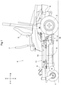
- Fig. 1 shows arrow F to indicate the forward direction of the vehicle body, arrow B to indicate the backward direction of the vehicle body, arrow U to indicate the upward direction of the vehicle body, and arrow D to indicate the downward direction of the vehicle body.
- the front side of the drawing corresponds to the leftward direction of the vehicle body, whereas the back side of the drawing corresponds to the rightward direction of the vehicle body.
- the riding-type mower includes a travel vehicle body provided with a pair of left and right freely rotatable front wheels 1 and a pair of left and right drivable rear wheels 2.
- the pair of left and right front wheels 1 are each a caster wheel.
- the pair of left and right rear wheels 2 are drivable by a pair of left and right travel electric motors 3, respectively.
- the riding-type mower includes a driver section 4 at a front portion of the travel vehicle body.
- the driver section 4 includes a driver's seat 5, a driver section floor 6 present in front of and below the driver's seat 5, and a pair of left and right control levers 7 present to the left and right of the driver's seat 5 and operable to move and steer the travel vehicle body.
- the driver can move and steer the travel vehicle body with use of the left and right control levers 7 by swinging the left and right control levers 7 individually in the front-back direction to change the respective rotation directions and rotation speeds of the left and right travel electric motors 3 by means of respective linkage mechanisms (not shown in the drawings) between the left and right control levers 7 and the left and right travel electric motors 3.
- the riding-type mower includes a battery pack 8 present at a back portion of the travel vehicle body and configured to supply electric power to, for example, the travel electric motors 3.
- the riding-type mower includes, between the front wheels 1 and the rear wheels 2, a mowing device 9 configured to mow turf and grass and discharge mown turf and grass (hereinafter referred to simply as "mown grass”) laterally outward of the vehicle body.
- the mowing device 9 is supported by a vehicle body frame 10 via a link mechanism 11 configured to allow the mowing device 9 to be lifted and lowered relative to the vehicle body frame 10.
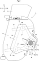
- Fig. 2 is a plan view of the mowing device 9 as a whole.
- the description below of the mowing device 9 refers to Fig. 2 , which shows arrow F1 to indicate the forward direction of the device, arrow B1 to indicate the backward direction of the device, arrow L1 to indicate the leftward direction of the device, and arrow R1 to indicate the rightward direction of the device.
- the mowing device 9 is oriented so that its front-back direction is identical to the front-back direction of the travel vehicle body.
- the mowing device 9 includes a cutting blade housing 12 and two cutting blades 13 present inside the cutting blade housing 12 and drivable to rotate.
- the cutting blades 13 are arranged next to each other in the left-right direction of the device.
- the cutting blades 13 are each in the shape of a blade, and are each supported by the cutting blade housing 12 via a rotary shaft 13a extending in the up-down direction of the device.
- the mowing device 9 includes, to the right of the cutting blade housing 12, a discharge guide 14 connected to the cutting blade housing 12 and configured to guide mown grass discharged from the cutting blade housing 12 toward a lateral side of the vehicle body.
- the mowing device 9 includes a motor device M supported by a back portion of the cutting blade housing 12 and including an electric motor 15 configured to drive the cutting blades 13.
- the mowing device 9 includes, on an upper surface side of the cutting blade housing 12, (i) a power transmission belt 16 configured to transmit power from the electric motor 15 to the cutting blades 13 and (ii) a power transmission section cover 17 covering, for example, the power transmission belt 16.
- the power transmission section cover 17 includes a back portion 17a covering the motor device M.
- the motor device M includes an electric motor 15 present under the back portion 17a of the power transmission section cover 17 and configured to drive the cutting blades 13.
- the electric motor 15 includes a motor section 15b including, for example, a rotor and an output shaft 15a protruding from the motor section 15b.
- the motor section 15b is, as illustrated in Fig. 2 , in the shape of a circle with the output shaft 15a as its center in a plan view.
- the output shaft 15a protrudes upward from the motor section 15b.
- the motor section 15b includes a front portion between (i) an arc-shaped back portion of that part of the cutting blade housing 12 which contains the left cutting blade 13 and (ii) an arc-shaped back portion of that part of the cutting blade housing 12 which contains the right cutting blade 13.
- the electric motor 15 is attached to a motor support 18 extending backward from a back portion of the cutting blade housing 12.
- the electric motor 15 is thereby supported by the cutting blade housing 12 via the motor support 18.
- the motor support 18, as illustrated in Figs. 2 and 3 includes (i) a motor mount section 18a which extends backward from the cutting blade housing 12 and on which the motor section 15b is mounted, (ii) a connecting bar section 18b connecting a back portion of the motor mount section 18a to the cutting blade housing 12, and (iii) an upper support section 18c extending from the motor mount section 18a to a height above the motor section 15b and supporting an upper portion of the motor section 15b from above.
- the motor device M includes an output pulley 20 on the output shaft 15a.
- the motor device M includes a power transmission belt 16 wound around the output pulley 20 and cutting blade drive pulleys 21 each present on the rotary shaft 13a of the corresponding cutting blade 13.
- the cutting blade drive pulleys 21 are each present on that portion of the corresponding rotary shaft 13a which protrudes upward from the cutting blade housing 12.
- the power transmission belt 16 is wound around a guide wheel 22 between the left cutting blade drive pulley 21 and the output pulley 20.
- the guide wheel 22 is supported by the cutting blade housing 12.
- the motor device M is configured such that the electric motor 15 transmits power from the output shaft 15a to each cutting blade drive pulley 21 via the power transmission belt 16 and that each cutting blade drive pulley 21 then transmits power to the corresponding cutting blade 13 via its rotary shaft 13a, whereby the electric motor 15 drives the cutting blades 13.
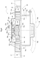
- the motor device M is, as illustrated in Fig. 3 , provided with a motor cooling mechanism 23 configured to cool the electric motor 15 so that the electric motor 15 is drivable continuously over an extended period of time.
- the motor cooling mechanism 23, as illustrated in Fig. 3 includes a rotary fan 24 configured to cool the electric motor 15.
- the rotary fan 24 is supported by the output shaft 15a in such a manner as to be drivable by the output shaft 15a to rotate.
- the rotary fan 24 includes a fan section 24a and a connecting section 24b inside the fan section 24a.
- the fan section 24a includes blower fins 24f arranged apart from each other along the circumference of the rotary fan 24.
- the connecting section 24b has an attachment hole 24c at a central portion thereof.
- the output pulley 20 is provided with a fan support section 20a protruding upward from a side portion of the output pulley 20.
- the connecting section 24b is fitted around an upper end portion 20b of the fan support section 20a with the upper end portion 20b in the attachment hole 24c.
- the connecting section 24b includes a depressed portion 24d in an inner circumferential portion thereof, whereas the upper end portion 20b includes a protruding portion 20c fitted in the depressed portion 24d.
- the connecting section 24b and the fan support section 20a are thereby engaged with each other in such a manner as to be incapable of rotation relative to each other.
- the rotary fan 24 is supported by the output shaft 15a via the output pulley 20.
- the rotary fan 24 and the output shaft 15a are connected to each other via the output pulley 20 in an interlocking manner, so that the output shaft 15a is capable of driving the rotary fan 24 to rotate.
- the output pulley 20 is present on the output shaft 15a between the rotary fan 24 and the motor section 15b.
- the motor device M includes a fan cover 25 that surrounds and covers the rotary fan 24.
- the fan cover 25 protrudes upward from the back portion 17a of the power transmission section cover 17.
- the fan cover 25 includes a top plate portion 25a having a plurality of vent holes 26 that allow the fan cover 25 to take in cooling air from outside.
- the vent holes 26 are each in the shape of a slit for the present embodiment, but are not limited as such.
- the vent holes 26 may alternatively each have any of various shapes such as a circle, a rectangle, or an ellipse.
- the power transmission section cover 17 has, at an edge portion thereof, a plurality of exhaust ports 32 that allow air from the rotary fan 24 to be discharged.
- the rotary fan 24 includes a cutter section 27 configured to cut a foreign object such as mown grass having entered the fan cover 25.
- the cutter section 27 is in the form of a circular screen, and is present at an upper end portion of the rotary fan 24 in such a manner as to face the top plate portion 25a of the fan cover 25.
- the cutter section 27 has a plurality of through holes 27a.
- the cutter section 27 is provided with a connecting cylindrical portion 28 extending from a central portion of the cutter section 27 toward the fan support section 20a.
- the connecting cylindrical portion 28 includes, at a lower end portion thereof, a flange portion 28a placed on the connecting section 24b of the rotary fan 24 and fastened to the fan support section 20a with use of a connecting bolt.
- the cutter section 27 is thus supported by the rotary fan 24 in such a manner as to be incapable of rotation relative to the rotary fan 24.
- the flange portion 28a serves to prevent the rotary fan 24 from becoming detached from the fan support section 20a.
- the through holes 27a are each in the shape of a circle for the present embodiment, but are not limited as such.
- the through holes 27a may alternatively each have any of various shapes such as a slit, a rectangle, or an ellipse. If a foreign object enters the fan cover 25 through a vent hole 26 to have one end in a through hole 27a and the other end in the vent hole 26, the foreign object is caught by the top plate portion 25a and the cutter section 27. In this state, the cutter section 27 is rotated relative to the top plate portion 25a to cut the foreign object.
- the motor cooling mechanism 23 is arranged such that the rotary fan 24 is drivable by the electric motor 15 to rotate about the axis Y of the output shaft 15a.
- the rotation of the rotary fan 24 takes in cooling air from outside the fan cover 25 through the vent holes 26.
- the cooling air flows from an inner portion of the rotary fan 24 through a space between the blower fins 24f to a space around the rotary fan 24.
- the cooling air is then partly supplied to the output pulley 20 to cool the output pulley 20 and the power transmission belt 16.
- the cooling air having flown to the space around the rotary fan 24 is also partly supplied to the motor section 15b through the upper support section 18c or directly to the motor section 15b past a space in which the upper support section 18c is absent.
- the cooling air thereby cools the motor section 15b. Cooling air having entered the power transmission section cover 17 flows through the exhaust ports 32 or openings 33 in the cutting blade housing 12 to outside the power transmission section cover 17. If the motor device M has taken cooling air into the fan cover 25 together with a foreign object such as mown grass through a vent hole 26, the cutter section 27 shreds the foreign object. The motor device M discharges the shredded foreign object together with cooling air.
- the present invention is applicable to a mowing device including a cutting blade housing, cutting blades present inside the cutting blade housing and drivable to rotate, and an electric motor supported by the cutting blade housing and configured to drive the cutting blades.
Landscapes
- Life Sciences & Earth Sciences (AREA)
- Environmental Sciences (AREA)
- Harvester Elements (AREA)
- Engineering & Computer Science (AREA)
- Power Engineering (AREA)
Abstract
Description
- The present invention relates to a mowing device.
- A mowing device may include a cutting blade housing and cutting blades present inside the cutting blade housing and drivable to rotate. An example of such a mowing device is the mower unit disclosed in
Patent Literature 1. The mower unit includes a "mower deck" as the cutting blade housing and "blades" as the cutting blades. A mowing device of this type may include, as disclosed inPatent Literature 1, an electric motor ("work motor" in Patent Literature 1) supported by the cutting blade housing and configured to drive the cutting blades. - Patent Literature
-
Patent Literature 1Japanese Unexamined Patent Application Publication, Tokukai, No. 2019-17278 - The above mowing device will become unable to continue work if the electric motor has been driven and heated up so much as to seize up.
- The present invention has an object of providing an inexpensive mowing device configured to drive a cutting blade with use of an electric motor and yet capable of continuing mowing work over an extended period of time.
- A mowing device as an embodiment of the present invention includes: a cutting blade housing; a cutting blade present inside the cutting blade housing and drivable to rotate; and an electric motor supported by the cutting blade housing and configured to drive the cutting blade, wherein the electric motor includes: a motor section; and an output shaft protruding from the motor section, and the mowing device further includes a rotary fan supported by the output shaft and drivable by the output shaft to rotate to supply cooling air to the motor section.
- The above arrangement allows the rotary fan to be driven by the electric motor to supply cooling air to the motor section and cool the motor section. This prevents the electric motor from becoming heated up excessively, and thereby prevents the electric motor from becoming broken down. The above arrangement, in other words, allows the mowing device to continue mowing work over an extended period of time. Further, the simple structure of the rotary fan being supported by the output shaft allows production of an inexpensive mowing device.
- A mowing device as a preferable embodiment of the present invention includes: a fan cover covering the rotary fan and having a vent hole, wherein the rotary fan supplies the cooling air to the motor section by taking in the cooling air from outside the fan cover through the vent hole, and the rotary fan includes a cutter section configured to cut a foreign object having entered the fan cover through the vent hole.
- The above arrangement allows the cutter section to cut a foreign object such as mown grass having entered the fan cover. Such a foreign object and/or the like is thus cut to shreds and easily discharged from the fan cover with use of, for example, cooling air. The above arrangement thereby prevents a foreign object and/or the like having entered the fan cover from remaining on, for example, the motor section to prevent the cooling effect from becoming decreased and more reliably prevent the electric motor from becoming heated up excessively.
- A mowing device as a preferable embodiment of the present invention is arranged such that the motor section includes a cooling fin section configured to dissipate heat of the motor section, and the cooling fin section receives the cooling air supplied by the rotary fan.
- The above arrangement allows heat of the motor section to be conducted to the cooling fin section and then dissipated by means of the cooling fin section. The above arrangement also promotes dissipation of heat from the cooling fin section due to cooling air that the rotary fan supplies to the cooling fin section. The above arrangement thereby cools the motor section effectively. This more reliably prevents the electric motor from becoming heated up excessively, and thereby effectively prevents the electric motor from becoming broken down.
- A mowing device as a preferable embodiment of the present invention is arranged such that the cooling fin section includes a plurality of linear fins present around the output shaft in a plan view.
- The above arrangement involves linear fins present over a wide area around the motor section in a plan view. This allows the electric motor to be cooled more effectively through heat dissipation by the cooling fin section.
- A mowing device as a preferable embodiment of the present invention is arranged such that the plurality of linear fins extend radially from the output shaft.
- The above arrangement allows cooling air supplied by the rotary fan to the cooling fin section to flow along the plurality of linear fins from the output shaft side to the opposite side. This promotes heat dissipation by the cooling fin section, and thereby allows the electric motor to be cooled more effectively.
- A mowing device as a preferable embodiment of the present invention includes: an output pulley which is present on the output shaft and between the rotary fan and the motor section and around which a power transmission belt is wound, the power transmission belt interlocking the output shaft and the cutting blade with each other.
- The above arrangement allows cooling air supplied from the rotary fan toward the motor section to be brought to the output pulley, meaning that the rotary fan is usable also as a means of cooling the output pulley. This simple structure prevents the output pulley and the power transmission belt from becoming heated up.
- A mowing device as a preferable embodiment of the present invention is arranged such that the output pulley and the plurality of linear fins coincide with each other with respect to an axial direction of the output shaft.
- The above arrangement allows the rotary fan to be near both the linear fins and the output pulley. This allows the rotary fan to supply cooling air to the linear fins and the output pulley in such a manner as to cool the linear fins and the output pulley effectively.
- A mowing device as a preferable embodiment of the present invention is arranged such that the output shaft protrudes upward from the motor section.
- The above arrangement allows the rotary fan to be above the motor section. This allows cooling air to be taken in from above the cutting blade housing, and prevents, for example, mown grass from entering the motor section easily.
-
-
Fig. 1 is a left side view of a riding type mower as a whole. -
Fig. 2 is a plan view of a mowing device as a whole. -
Fig. 3 is a cross-sectional view of the mowing device taken along line III-III inFig. 2 . -
Fig. 4 is a cross-sectional view of a motor cooling mechanism for an alternative embodiment. -
Fig. 5 is a plan view of a motor cooling mechanism for an alternative embodiment. -
Fig. 6 is a graph that shows a change in the temperature of the electric motor of a mowing device which change is caused as the mowing device is driven idly. - The description below deals with an example embodiment of the present invention with reference to drawings.
- The embodiment described below is a riding-type mower including a travel vehicle body.
Fig. 1 shows arrow F to indicate the forward direction of the vehicle body, arrow B to indicate the backward direction of the vehicle body, arrow U to indicate the upward direction of the vehicle body, and arrow D to indicate the downward direction of the vehicle body. The front side of the drawing corresponds to the leftward direction of the vehicle body, whereas the back side of the drawing corresponds to the rightward direction of the vehicle body. - As illustrated in
Fig. 1 , the riding-type mower includes a travel vehicle body provided with a pair of left and right freely rotatablefront wheels 1 and a pair of left and right drivablerear wheels 2. The pair of left and rightfront wheels 1 are each a caster wheel. The pair of left and rightrear wheels 2 are drivable by a pair of left and right travelelectric motors 3, respectively. The riding-type mower includes adriver section 4 at a front portion of the travel vehicle body. Thedriver section 4 includes a driver'sseat 5, adriver section floor 6 present in front of and below the driver'sseat 5, and a pair of left and right control levers 7 present to the left and right of the driver'sseat 5 and operable to move and steer the travel vehicle body. The driver can move and steer the travel vehicle body with use of the left and right control levers 7 by swinging the left and right control levers 7 individually in the front-back direction to change the respective rotation directions and rotation speeds of the left and right travelelectric motors 3 by means of respective linkage mechanisms (not shown in the drawings) between the left and right control levers 7 and the left and right travelelectric motors 3. The riding-type mower includes abattery pack 8 present at a back portion of the travel vehicle body and configured to supply electric power to, for example, the travelelectric motors 3. The riding-type mower includes, between thefront wheels 1 and therear wheels 2, amowing device 9 configured to mow turf and grass and discharge mown turf and grass (hereinafter referred to simply as "mown grass") laterally outward of the vehicle body. Themowing device 9 is supported by avehicle body frame 10 via alink mechanism 11 configured to allow themowing device 9 to be lifted and lowered relative to thevehicle body frame 10. -
Fig. 2 is a plan view of themowing device 9 as a whole. The description below of themowing device 9 refers toFig. 2 , which shows arrow F1 to indicate the forward direction of the device, arrow B1 to indicate the backward direction of the device, arrow L1 to indicate the leftward direction of the device, and arrow R1 to indicate the rightward direction of the device. Themowing device 9 is oriented so that its front-back direction is identical to the front-back direction of the travel vehicle body. - As illustrated in
Fig. 2 , themowing device 9 includes acutting blade housing 12 and two cuttingblades 13 present inside thecutting blade housing 12 and drivable to rotate. Thecutting blades 13 are arranged next to each other in the left-right direction of the device. Thecutting blades 13 are each in the shape of a blade, and are each supported by thecutting blade housing 12 via arotary shaft 13a extending in the up-down direction of the device. Themowing device 9 includes, to the right of thecutting blade housing 12, adischarge guide 14 connected to thecutting blade housing 12 and configured to guide mown grass discharged from thecutting blade housing 12 toward a lateral side of the vehicle body. Themowing device 9 includes a motor device M supported by a back portion of thecutting blade housing 12 and including anelectric motor 15 configured to drive the cuttingblades 13. Themowing device 9 includes, on an upper surface side of thecutting blade housing 12, (i) apower transmission belt 16 configured to transmit power from theelectric motor 15 to thecutting blades 13 and (ii) a power transmission section cover 17 covering, for example, thepower transmission belt 16. The power transmission section cover 17 includes aback portion 17a covering the motor device M. - As illustrated in
Figs. 2 and3 , the motor device M includes anelectric motor 15 present under theback portion 17a of the powertransmission section cover 17 and configured to drive the cuttingblades 13. Theelectric motor 15 includes amotor section 15b including, for example, a rotor and anoutput shaft 15a protruding from themotor section 15b. Themotor section 15b is, as illustrated inFig. 2 , in the shape of a circle with theoutput shaft 15a as its center in a plan view. Theoutput shaft 15a, as illustrated inFig. 3 , protrudes upward from themotor section 15b. Themotor section 15b includes a front portion between (i) an arc-shaped back portion of that part of thecutting blade housing 12 which contains theleft cutting blade 13 and (ii) an arc-shaped back portion of that part of thecutting blade housing 12 which contains theright cutting blade 13. - The
electric motor 15 is attached to amotor support 18 extending backward from a back portion of thecutting blade housing 12. Theelectric motor 15 is thereby supported by thecutting blade housing 12 via themotor support 18. Themotor support 18, as illustrated inFigs. 2 and3 , includes (i) amotor mount section 18a which extends backward from thecutting blade housing 12 and on which themotor section 15b is mounted, (ii) a connectingbar section 18b connecting a back portion of themotor mount section 18a to thecutting blade housing 12, and (iii) anupper support section 18c extending from themotor mount section 18a to a height above themotor section 15b and supporting an upper portion of themotor section 15b from above. - As illustrated in
Figs. 2 and3 , the motor device M includes anoutput pulley 20 on theoutput shaft 15a. The motor device M includes apower transmission belt 16 wound around theoutput pulley 20 and cutting blade drive pulleys 21 each present on therotary shaft 13a of thecorresponding cutting blade 13. The cutting blade drive pulleys 21 are each present on that portion of the correspondingrotary shaft 13a which protrudes upward from thecutting blade housing 12. As illustrated inFig. 2 , thepower transmission belt 16 is wound around aguide wheel 22 between the left cutting blade drivepulley 21 and theoutput pulley 20. Theguide wheel 22 is supported by thecutting blade housing 12. - The motor device M is configured such that the
electric motor 15 transmits power from theoutput shaft 15a to each cutting blade drivepulley 21 via thepower transmission belt 16 and that each cutting blade drivepulley 21 then transmits power to thecorresponding cutting blade 13 via itsrotary shaft 13a, whereby theelectric motor 15 drives thecutting blades 13. - The motor device M is, as illustrated in
Fig. 3 , provided with amotor cooling mechanism 23 configured to cool theelectric motor 15 so that theelectric motor 15 is drivable continuously over an extended period of time. - The
motor cooling mechanism 23, as illustrated inFig. 3 , includes arotary fan 24 configured to cool theelectric motor 15. Therotary fan 24 is supported by theoutput shaft 15a in such a manner as to be drivable by theoutput shaft 15a to rotate. Specifically, as illustrated inFig. 3 , therotary fan 24 includes afan section 24a and a connectingsection 24b inside thefan section 24a. Thefan section 24a includesblower fins 24f arranged apart from each other along the circumference of therotary fan 24. The connectingsection 24b has anattachment hole 24c at a central portion thereof. Theoutput pulley 20 is provided with afan support section 20a protruding upward from a side portion of theoutput pulley 20. The connectingsection 24b is fitted around anupper end portion 20b of thefan support section 20a with theupper end portion 20b in theattachment hole 24c. The connectingsection 24b includes adepressed portion 24d in an inner circumferential portion thereof, whereas theupper end portion 20b includes a protrudingportion 20c fitted in thedepressed portion 24d. The connectingsection 24b and thefan support section 20a are thereby engaged with each other in such a manner as to be incapable of rotation relative to each other. Therotary fan 24 is supported by theoutput shaft 15a via theoutput pulley 20. Therotary fan 24 and theoutput shaft 15a are connected to each other via theoutput pulley 20 in an interlocking manner, so that theoutput shaft 15a is capable of driving therotary fan 24 to rotate. - As illustrated in
Fig. 3 , theoutput pulley 20 is present on theoutput shaft 15a between therotary fan 24 and themotor section 15b. - As illustrated in
Figs. 2 and3 , the motor device M includes afan cover 25 that surrounds and covers therotary fan 24. Thefan cover 25 protrudes upward from theback portion 17a of the powertransmission section cover 17. Thefan cover 25 includes atop plate portion 25a having a plurality of vent holes 26 that allow thefan cover 25 to take in cooling air from outside. The vent holes 26 are each in the shape of a slit for the present embodiment, but are not limited as such. The vent holes 26 may alternatively each have any of various shapes such as a circle, a rectangle, or an ellipse. As illustrated inFigs. 2 and3 , the power transmission section cover 17 has, at an edge portion thereof, a plurality ofexhaust ports 32 that allow air from therotary fan 24 to be discharged. - As illustrated in
Fig. 3 , therotary fan 24 includes acutter section 27 configured to cut a foreign object such as mown grass having entered thefan cover 25. Thecutter section 27 is in the form of a circular screen, and is present at an upper end portion of therotary fan 24 in such a manner as to face thetop plate portion 25a of thefan cover 25. Thecutter section 27 has a plurality of throughholes 27a. Thecutter section 27 is provided with a connectingcylindrical portion 28 extending from a central portion of thecutter section 27 toward thefan support section 20a. The connectingcylindrical portion 28 includes, at a lower end portion thereof, aflange portion 28a placed on the connectingsection 24b of therotary fan 24 and fastened to thefan support section 20a with use of a connecting bolt. Thecutter section 27 is thus supported by therotary fan 24 in such a manner as to be incapable of rotation relative to therotary fan 24. Theflange portion 28a serves to prevent therotary fan 24 from becoming detached from thefan support section 20a. The throughholes 27a are each in the shape of a circle for the present embodiment, but are not limited as such. The throughholes 27a may alternatively each have any of various shapes such as a slit, a rectangle, or an ellipse. If a foreign object enters thefan cover 25 through avent hole 26 to have one end in a throughhole 27a and the other end in thevent hole 26, the foreign object is caught by thetop plate portion 25a and thecutter section 27. In this state, thecutter section 27 is rotated relative to thetop plate portion 25a to cut the foreign object. - The
motor cooling mechanism 23 is arranged such that therotary fan 24 is drivable by theelectric motor 15 to rotate about the axis Y of theoutput shaft 15a. The rotation of therotary fan 24 takes in cooling air from outside thefan cover 25 through the vent holes 26. The cooling air flows from an inner portion of therotary fan 24 through a space between theblower fins 24f to a space around therotary fan 24. The cooling air is then partly supplied to theoutput pulley 20 to cool theoutput pulley 20 and thepower transmission belt 16. The cooling air having flown to the space around therotary fan 24 is also partly supplied to themotor section 15b through theupper support section 18c or directly to themotor section 15b past a space in which theupper support section 18c is absent. The cooling air thereby cools themotor section 15b. Cooling air having entered the power transmission section cover 17 flows through theexhaust ports 32 oropenings 33 in thecutting blade housing 12 to outside the powertransmission section cover 17. If the motor device M has taken cooling air into thefan cover 25 together with a foreign object such as mown grass through avent hole 26, thecutter section 27 shreds the foreign object. The motor device M discharges the shredded foreign object together with cooling air. -
- (1)
Fig. 4 is a cross-sectional view of amotor cooling mechanism 30 for an alternative embodiment. Themotor cooling mechanism 30 for an alternative embodiment includes arotary fan 24, and also includes acooling fin section 31 for themotor section 15b.
As illustrated inFigs. 4 and5 , the coolingfin section 31 receives heat from themotor section 15b through heat transfer involving contact with themotor section 15b and heat transfer involving no contact with themotor section 15b. The coolingfin section 31 also dissipates heat that it has received. The coolingfin section 31 is oriented to face therotary fan 24 to receive cooling air from therotary fan 24.
The coolingfin section 31 is mounted over themotor section 15b. Theupper support section 18c is connected to thecooling fin section 31 and themotor mount section 18a. The coolingfin section 31 is pressed by theupper support section 18c against themotor section 15b, so that the coolingfin section 31 serves to fix theelectric motor 15 to themotor mount section 18a.
The coolingfin section 31, as illustrated inFigs. 4 and5 , includes amount section 31a placed on and connected to themotor section 15b and a plurality oflinear fins 31b protruding upward from themount section 31a. Thelinear fins 31b are each, for example, a plate-shaped fin standing on themount section 31a. Thelinear fins 31b each have a predetermined height and a predetermined thickness in a plan view. Thelinear fins 31b are, however, not limited as such, and may each be a member having any shape with a predetermined surface area and supported by themount section 31a. The plurality oflinear fins 31b are, as illustrated inFig. 5 , arranged around theoutput shaft 15a in a pattern similar to a radial pattern with theoutput shaft 15a as the center. Themount section 31a has, at a portion forward of themotor section 15b, a throughhole 29 that allows air to pass therethrough. The throughhole 29 is, as illustrated inFig. 5 , in the shape of a substantial triangle in a plan view. As illustrated inFig. 4 , thoselinear fins 31b which are under thepower transmission belt 16 each protrude from themount section 31a to a height smaller than the height to which each of the otherlinear fins 31b protrudes from themount section 31a.
As illustrated inFig. 4 , theoutput pulley 20 and the plurality oflinear fins 31b coincide with each other with respect to the axial direction of theoutput shaft 15a. This allows therotary fan 24 to be near both thelinear fins 31b and theoutput pulley 20.
Themotor cooling mechanism 30 is configured such that heat generated by themotor section 15b is conducted to thecooling fin section 31 and is then dissipated by thelinear fins 31b, whereby the coolingfin section 31 cools theelectric motor 15. Therotary fan 24 takes in cooling air from outside thefan cover 25. The cooling air flows through a space around therotary fan 24, and is supplied to thecooling fin section 31. The cooling air then flows along the plurality oflinear fins 31b from the output shaft side (that is, the side close to theoutput shaft 15a) toward the opposite side (that is, the side far from theoutput shaft 15a). This allows the cooling air to cool thelinear fins 31b and promote heat dissipation by thelinear fins 31b. The cooling air having flown along thelinear fins 31b toward the opposite side flows through theexhaust ports 32 and theopenings 33 to be discharged from the powertransmission section cover 17.
Fig. 6 is a graph that shows the result of a test on a change in the temperature of theelectric motor 15 of amowing device 9 including the coolingfin section 31 and therotary fan 24 which change is caused as themowing device 9 is driven idly. The graph has (i) a horizontal axis indicative of the time length over which themowing device 9 is driven idly and (ii) a vertical axis indicative of the increase in the temperature of theelectric motor 15. The temperature increase is a difference between the temperature of theelectric motor 15 and that of outside air. The graph shows (i) circles to indicate a temperature change for a case involving no coolingfin section 31 orrotary fan 24 and (ii) triangles to indicate a temperature change for a case involving the coolingfin section 31 and therotary fan 24. - (2) The embodiment described above is arranged such that the
output shaft 15a protrudes upward from themotor section 15b and that theoutput pulley 20 and therotary fan 24 are present above themotor section 15b. The embodiment may, however, be altered such that theoutput shaft 15a protrudes downward from themotor section 15b and that theoutput pulley 20 and therotary fan 24 are present below themotor section 15b. - (3) The embodiment described above is an example in which the
linear fins 31b are arranged in a pattern similar to a radial pattern with theoutput shaft 15a as the center. The present invention is, however, not limited to such an arrangement. The embodiment may be altered to include, for example, (i) linear fins extending in the left-right direction of thecutting blade housing 12 and arranged next to one another in the front-back direction of thecutting blade housing 12 or (ii) linear fins extending in the front-back direction of thecutting blade housing 12 and arranged next to another in the left-right direction of thecutting blade housing 12. - (4) The embodiment described above is an example in which the
output pulley 20 and thelinear fins 31b coincide with each other with respect to the axial direction of theoutput shaft 15a. The present invention is, however, not limited to such an arrangement. The embodiment may be altered, for instance, such that thelinear fins 31b are above or below theoutput pulley 20. - The present invention is applicable to a mowing device including a cutting blade housing, cutting blades present inside the cutting blade housing and drivable to rotate, and an electric motor supported by the cutting blade housing and configured to drive the cutting blades.
-
- 12
- Cutting blade housing
- 13
- Cutting blade
- 15
- Electric motor
- 15a
- Output shaft
- 15b
- Motor section
- 16
- Power transmission belt
- 20
- Output pulley
- 24
- Rotary fan
- 25
- Fan cover
- 26
- Vent hole
- 27
- Cutter section
- 31
- Cooling fin section
- 31b
- Linear fin
Claims (8)
- A mowing device (9), comprising:a cutting blade housing (12);a cutting blade (13) present inside the cutting blade housing and drivable to rotate; andan electric motor (15) supported by the cutting blade housing and configured to drive the cutting blade, whereinthe electric motor (15) includes:a motor section (15b); andan output shaft (15a) protruding from the motor section, andthe mowing device (9) further comprises a rotary fan (24) supported by the output shaft and drivable by the output shaft to rotate to supply cooling air to the motor section.
- The mowing device according to claim 1, further comprising:a fan cover (25) covering the rotary fan and having a vent hole (26), whereinthe rotary fan (24) supplies the cooling air to the motor section by taking in the cooling air from outside the fan cover through the vent hole, andthe rotary fan includes a cutter section (27) configured to cut a foreign object having entered the fan cover through the vent hole.
- The mowing device according to claim 1 or 2, wherein
the motor section (15b) includes a cooling fin section configured to dissipate heat of the motor section, and
the cooling fin section (31) receives the cooling air supplied by the rotary fan. - The mowing device according to claim 3, wherein
the cooling fin section (31) includes a plurality of linear fins (31b) present around the output shaft (15a) in a plan view. - The mowing device according to claim 4, wherein
the plurality of linear fins (31b) extend radially from the output shaft (15a). - The mowing device according to claim 4 or 5, further comprising:
an output pulley (20) which is present on the output shaft (15a) and between the rotary fan (24) and the motor section (15b) and around which a power transmission belt is wound, the power transmission belt interlocking the output shaft and the cutting blade with each other. - The mowing device according to claim 6, wherein
the output pulley (20) and the plurality of linear fins (31b) coincide with each other with respect to an axial direction of the output shaft (15a). - The mowing device according to any one of claims 1 to 7, wherein
the output shaft (15a) protrudes upward from the motor section (15b).
Applications Claiming Priority (1)
| Application Number | Priority Date | Filing Date | Title |
|---|---|---|---|
| JP2020155678A JP7390998B2 (en) | 2020-09-16 | 2020-09-16 | grass cutting equipment |
Publications (1)
| Publication Number | Publication Date |
|---|---|
| EP3970470A1 true EP3970470A1 (en) | 2022-03-23 |
Family
ID=76374980
Family Applications (1)
| Application Number | Title | Priority Date | Filing Date |
|---|---|---|---|
| EP21178738.7A Pending EP3970470A1 (en) | 2020-09-16 | 2021-06-10 | Mowing device |
Country Status (3)
| Country | Link |
|---|---|
| US (1) | US12396389B2 (en) |
| EP (1) | EP3970470A1 (en) |
| JP (1) | JP7390998B2 (en) |
Families Citing this family (1)
| Publication number | Priority date | Publication date | Assignee | Title |
|---|---|---|---|---|
| JP7390998B2 (en) * | 2020-09-16 | 2023-12-04 | 株式会社クボタ | grass cutting equipment |
Citations (4)
| Publication number | Priority date | Publication date | Assignee | Title |
|---|---|---|---|---|
| EP2374346A1 (en) * | 2010-04-08 | 2011-10-12 | Kanzaki Kokyukoki Mfg. Co., Ltd. | Electric zero-turn working vehicle |
| US20170135283A1 (en) * | 2015-11-12 | 2017-05-18 | Kubota Corporation | Grass Mower Machine |
| JP2019017278A (en) | 2017-07-13 | 2019-02-07 | 株式会社クボタ | Mower unit |
| WO2019123658A1 (en) * | 2017-12-22 | 2019-06-27 | 本田技研工業株式会社 | Prime mover of work machine |
Family Cites Families (124)
| Publication number | Priority date | Publication date | Assignee | Title |
|---|---|---|---|---|
| US1868918A (en) * | 1931-02-26 | 1932-07-26 | Tamis C Schenk | Lawn mower |
| US3593505A (en) * | 1968-09-04 | 1971-07-20 | Toro Mfg Corp | Mower motor cooling system |
| JPS516070U (en) * | 1974-07-03 | 1976-01-17 | ||
| JPS6018581Y2 (en) * | 1978-01-10 | 1985-06-05 | 三菱農機株式会社 | Dust control equipment for air-cooled internal combustion engines |
| DE3232895C2 (en) * | 1982-09-04 | 1986-02-13 | Gutbrod-Werke GmbH, 6601 Bübingen | Sickle lawn mower with electric drive |
| US4838908A (en) * | 1988-07-27 | 1989-06-13 | Kohler Co. | Engine air intake screen assembly |
| JP2963627B2 (en) * | 1994-10-20 | 1999-10-18 | 株式会社クボタ | Mower |
| US5638668A (en) * | 1995-06-26 | 1997-06-17 | The Toro Company | Lawn mower having nested deck and liner |
| US5638667A (en) * | 1995-06-26 | 1997-06-17 | The Toro Company | Mulching mower |
| DE19962365A1 (en) * | 1999-12-23 | 2001-06-28 | Al Maghrebi-Bassam | Lawn mower has horizontal, rotating cutter blade in housing divided by horizontal partition with central opening which is concentric with motor, section of housing above partition containing propeller blade which creates updraft |
| JP2002027818A (en) * | 2000-07-13 | 2002-01-29 | Yanmar Agricult Equip Co Ltd | Mower |
| JP2003154857A (en) * | 2001-11-19 | 2003-05-27 | Kubota Corp | Mower |
| CN1311166C (en) * | 2001-12-21 | 2007-04-18 | 松下电器产业株式会社 | Electrically power blower |
| JP3771507B2 (en) * | 2002-03-26 | 2006-04-26 | 本田技研工業株式会社 | Lawn mower |
| JP3828497B2 (en) * | 2003-03-06 | 2006-10-04 | 株式会社筑水キャニコム | Mower power transmission mechanism |
| JP3953018B2 (en) * | 2003-10-10 | 2007-08-01 | 松下電工株式会社 | Lawn mower |
| JP4546911B2 (en) * | 2005-09-29 | 2010-09-22 | 株式会社クボタ | Rear discharge type mowing device |
| JP2007116956A (en) * | 2005-10-26 | 2007-05-17 | Matsushita Electric Works Ltd | Lawn mower |
| JP4866617B2 (en) * | 2006-01-23 | 2012-02-01 | ブイアイブイエンジニアリング株式会社 | Brush cutter |
| JP4791932B2 (en) * | 2006-10-16 | 2011-10-12 | 株式会社クボタ | Moore |
| WO2008048618A2 (en) * | 2006-10-17 | 2008-04-24 | Desa Ip. Llc | Hybrid electric device |
| JP2008125367A (en) | 2006-11-16 | 2008-06-05 | Hiroshima Industrial Promotion Organization | Recombinant cells and transgenic organisms producing recombinant proline hydroxylated human collagen |
| JP4897455B2 (en) * | 2006-12-07 | 2012-03-14 | 株式会社クボタ | Mower |
| JP2008162030A (en) | 2006-12-27 | 2008-07-17 | Casio Electronics Co Ltd | Manufacturing method of powder adhesive and its application / crimping method |
| JP5185842B2 (en) * | 2009-01-15 | 2013-04-17 | 株式会社クボタ | Mowing equipment |
| JP5033151B2 (en) * | 2009-02-12 | 2012-09-26 | 株式会社クボタ | Riding mower |
| JP3167453U (en) * | 2009-04-15 | 2011-04-28 | 棚田 克紀 | Vehicle having moistening device for pressure oil and electric power and mowing device |
| US8769917B1 (en) * | 2009-10-29 | 2014-07-08 | Jeffrey E. Howell | Battery-operated compact riding rotary mower |
| EP2444265B1 (en) * | 2009-12-09 | 2013-06-05 | Kanzaki Kokyukoki Mfg. Co., Ltd. | Electric transaxle unit |
| EP2389797B1 (en) * | 2010-05-27 | 2014-11-19 | Kanzaki Kokyukoki Mfg. Co., Ltd. | Electric lawn mower |
| JP5680346B2 (en) * | 2010-06-22 | 2015-03-04 | リョービ株式会社 | lawn mower |
| JP5473965B2 (en) * | 2011-03-01 | 2014-04-16 | 株式会社クボタ | Air-cooled engine |
| JP2012187025A (en) * | 2011-03-09 | 2012-10-04 | Kubota Corp | Riding working vehicle |
| JP5715855B2 (en) * | 2011-03-09 | 2015-05-13 | 株式会社クボタ | Passenger work vehicle |
| JP5530383B2 (en) * | 2011-03-14 | 2014-06-25 | 株式会社クボタ | Work vehicle |
| AU2011250778B1 (en) * | 2011-07-20 | 2012-07-26 | Troy Moncrieff | Profiling Device |
| JP5731323B2 (en) * | 2011-08-25 | 2015-06-10 | 株式会社クボタ | Riding mower |
| JP5596642B2 (en) * | 2011-08-31 | 2014-09-24 | 株式会社クボタ | Riding mower |
| CN202385497U (en) * | 2011-11-28 | 2012-08-22 | 韩聪 | Centrifugal mowing device |
| JP5859869B2 (en) * | 2012-02-10 | 2016-02-16 | 本田技研工業株式会社 | lawn mower |
| JP2013192311A (en) * | 2012-03-13 | 2013-09-26 | Kanzaki Kokyukoki Mfg Co Ltd | Rotary electric machine, rotary electric machine cooling system, and ground work vehicle |
| EP2656719B1 (en) * | 2012-04-24 | 2014-11-26 | Robert Bosch Gmbh | Airflow management |
| EP2656720B1 (en) * | 2012-04-24 | 2015-11-04 | Robert Bosch GmbH | Cutter guard for a lawn mower |
| US8746186B2 (en) | 2012-08-23 | 2014-06-10 | Briggs & Stratton Corporation | Rotating screen for centrifugal fan |
| JP6092006B2 (en) * | 2013-06-03 | 2017-03-08 | 株式会社クボタ | Mower |
| JP6066860B2 (en) * | 2013-08-05 | 2017-01-25 | 株式会社クボタ | Mower |
| US9155245B2 (en) * | 2013-09-05 | 2015-10-13 | Kubota Corporation | Work vehicle |
| EP2878189B1 (en) * | 2013-09-27 | 2017-11-01 | Kubota Corporation | Mower unit |
| JP6362841B2 (en) * | 2013-09-27 | 2018-07-25 | 株式会社クボタ | Mower unit |
| JP6207979B2 (en) * | 2013-11-11 | 2017-10-04 | 株式会社クボタ | Mower unit |
| EP2875713B1 (en) * | 2013-11-21 | 2016-10-19 | Robert Bosch Gmbh | Lawnmower |
| JP6247101B2 (en) * | 2014-01-10 | 2017-12-13 | 株式会社クボタ | Walking mower |
| JP6321970B2 (en) * | 2014-01-20 | 2018-05-09 | 株式会社クボタ | Lawn mower |
| JP6322025B2 (en) * | 2014-03-31 | 2018-05-09 | 株式会社クボタ | Lawn mower |
| JP6211470B2 (en) * | 2014-06-16 | 2017-10-11 | 株式会社クボタ | Moore |
| JP6322061B2 (en) * | 2014-06-16 | 2018-05-09 | 株式会社クボタ | Moore |
| US10130037B2 (en) * | 2014-12-31 | 2018-11-20 | Mean Green Products, LLC | Electric mower apparatus and method of use |
| JP6391526B2 (en) * | 2015-04-02 | 2018-09-19 | 株式会社クボタ | Battery pack and electric work vehicle |
| JP6433368B2 (en) * | 2015-04-10 | 2018-12-05 | 株式会社クボタ | Mowing vehicle |
| JP6509060B2 (en) * | 2015-07-13 | 2019-05-08 | 株式会社クボタ | Mowing machine |
| JP6639833B2 (en) * | 2015-08-28 | 2020-02-05 | 株式会社クボタ | Electric work vehicle |
| JP6479627B2 (en) * | 2015-10-29 | 2019-03-06 | 株式会社クボタ | Electric work vehicle |
| AU2017277925B2 (en) * | 2016-06-10 | 2022-04-14 | Husqvarna Ab | Stand-on lawn care vehicle |
| US11069936B2 (en) * | 2016-07-22 | 2021-07-20 | Kubota Corporation | Electric work vehicle |
| JP2018060998A (en) * | 2016-09-28 | 2018-04-12 | 株式会社村田製作所 | Medium |
| JP6824097B2 (en) * | 2017-04-13 | 2021-02-03 | 株式会社クボタ | Mowing device |
| JP6368816B2 (en) * | 2017-03-24 | 2018-08-01 | 株式会社クボタ | Moore |
| JP7313109B2 (en) * | 2017-04-24 | 2023-07-24 | 株式会社クボタ | electric lawn mower |
| JP7026452B2 (en) * | 2017-05-12 | 2022-02-28 | 株式会社クボタ | Electric work platform |
| JP6815276B2 (en) * | 2017-05-24 | 2021-01-20 | 株式会社クボタ | Mower |
| JP6842994B2 (en) * | 2017-05-24 | 2021-03-17 | 株式会社クボタ | Moor unit |
| JP6851260B2 (en) * | 2017-05-24 | 2021-03-31 | 株式会社クボタ | Electric work vehicle |
| US11102928B2 (en) * | 2017-07-13 | 2021-08-31 | Kubota Corporation | Electric work vehicle and mower unit |
| US10850622B2 (en) * | 2017-10-16 | 2020-12-01 | Kubota Corporation | Electric travelling vehicle and grass mower |
| JP7199144B2 (en) * | 2017-11-02 | 2023-01-05 | 株式会社クボタ | mower unit |
| US11382264B2 (en) * | 2017-11-02 | 2022-07-12 | Kubota Corporation | Mower unit for heat discharge and soundproofing |
| US11895947B2 (en) * | 2017-12-22 | 2024-02-13 | Honda Motor Co., Ltd. | Mower with motor cooling arrangement |
| JP7195066B2 (en) * | 2018-06-19 | 2022-12-23 | 株式会社クボタ | electric work vehicle |
| JP7117908B2 (en) * | 2018-06-19 | 2022-08-15 | 株式会社クボタ | mower |
| US11303240B2 (en) * | 2018-07-03 | 2022-04-12 | Kubota Corporation | Traveling control device |
| EP3821692B1 (en) * | 2018-09-27 | 2024-07-31 | Nanjing Chervon Industry Co., Ltd. | Lawn mower |
| JP7179569B2 (en) * | 2018-10-05 | 2022-11-29 | 株式会社マキタ | electric garden tools |
| JP7038639B2 (en) * | 2018-10-23 | 2022-03-18 | 株式会社クボタ | Non-excitation operation electromagnetic brake |
| JP7072499B2 (en) * | 2018-12-26 | 2022-05-20 | 株式会社クボタ | Electric work vehicle |
| JP7113741B2 (en) * | 2018-12-26 | 2022-08-05 | 株式会社クボタ | electric work vehicle |
| US11148518B2 (en) * | 2018-12-26 | 2021-10-19 | Kubota Corporation | Electric work vehicle arrangement |
| JP7199960B2 (en) * | 2018-12-26 | 2023-01-06 | 株式会社クボタ | electric lawn mower |
| US11486420B2 (en) * | 2018-12-26 | 2022-11-01 | Kubota Corporation | Electric work vehicle |
| JP7072498B2 (en) * | 2018-12-26 | 2022-05-20 | 株式会社クボタ | Electric work vehicle |
| JP2020145834A (en) * | 2019-03-06 | 2020-09-10 | 三菱電機株式会社 | Frame structure of electric motor and electric motor |
| JP7193385B2 (en) * | 2019-03-12 | 2022-12-20 | 株式会社クボタ | electric work vehicle |
| US11273716B2 (en) * | 2019-03-12 | 2022-03-15 | Kubota Corporation | Electric work vehicle |
| JP7106473B2 (en) * | 2019-03-12 | 2022-07-26 | 株式会社クボタ | electric work vehicle |
| US11973374B2 (en) * | 2019-04-24 | 2024-04-30 | Black & Decker Inc. | Outer rotor brushless motor having an axial fan |
| JP7193415B2 (en) * | 2019-05-21 | 2022-12-20 | 株式会社クボタ | mower unit |
| JP2021023230A (en) * | 2019-08-07 | 2021-02-22 | 本田技研工業株式会社 | Work machine |
| US12382865B2 (en) * | 2019-08-07 | 2025-08-12 | Honda Motor Co., Ltd. | Work machine with housing and case |
| US20210112710A1 (en) * | 2019-10-18 | 2021-04-22 | Bluebird Turf Products LLLP, A Delaware Limited Liability Partnership | Electric Power Hover Lawn Mower |
| CN110771355A (en) * | 2019-12-06 | 2020-02-11 | 常州格力博有限公司 | Lawn mower |
| CN110771354B (en) * | 2019-12-06 | 2025-01-28 | 格力博(江苏)股份有限公司 | Power head and lawn mower |
| CN111226569A (en) * | 2020-03-18 | 2020-06-05 | 福建省云宇机电有限公司 | Crawler-type automatic mower |
| JP7419130B2 (en) * | 2020-03-24 | 2024-01-22 | 株式会社クボタ | electric work vehicle |
| CN111492785B (en) * | 2020-04-26 | 2022-03-15 | 隆鑫通用动力股份有限公司 | An electric lawn mower |
| CN111919581B (en) * | 2020-07-17 | 2025-07-29 | 南京苏美达智能技术有限公司 | Sealing structure of automatic walking equipment |
| JP7390998B2 (en) * | 2020-09-16 | 2023-12-04 | 株式会社クボタ | grass cutting equipment |
| JP7362579B2 (en) * | 2020-09-16 | 2023-10-17 | 株式会社クボタ | electric work vehicle |
| US11895945B2 (en) * | 2020-12-04 | 2024-02-13 | The Toro Company | Assembly for adding ambient air to the cutting chamber of a walk power mower |
| JP7357598B2 (en) * | 2020-12-25 | 2023-10-06 | 株式会社クボタ | work vehicle |
| JP7378386B2 (en) * | 2020-12-25 | 2023-11-13 | 株式会社クボタ | grass mower |
| CN114793606A (en) * | 2021-01-22 | 2022-07-29 | 株式会社牧田 | Working machine |
| JP7450566B2 (en) * | 2021-02-05 | 2024-03-15 | 株式会社クボタ | electric work vehicle |
| US20220294242A1 (en) * | 2021-03-10 | 2022-09-15 | Techtronic Cordless Gp | Lawnmowers |
| US20220287238A1 (en) * | 2021-03-10 | 2022-09-15 | Techtronic Cordless Gp | Lawnmowers |
| US12296694B2 (en) * | 2021-03-10 | 2025-05-13 | Techtronic Cordless Gp | Lawnmowers |
| US11147209B1 (en) * | 2021-04-01 | 2021-10-19 | Ataco Steel Products Corp. | Riding lawn mower |
| JP2022158134A (en) * | 2021-04-01 | 2022-10-17 | 株式会社クボタ | mower unit |
| JP2022189307A (en) * | 2021-06-11 | 2022-12-22 | 株式会社荏原製作所 | Cooling fan and electric motor assembly |
| JP2023004671A (en) * | 2021-06-28 | 2023-01-17 | 株式会社クボタ | riding lawn mower |
| WO2023030296A1 (en) * | 2021-09-01 | 2023-03-09 | 格力博(江苏)股份有限公司 | Garden tool |
| JP7542498B2 (en) * | 2021-09-01 | 2024-08-30 | 株式会社クボタ | Work vehicle |
| JP7603561B2 (en) * | 2021-09-17 | 2024-12-20 | 株式会社クボタ | Power supply device for electric work vehicles |
| JP7669892B2 (en) * | 2021-09-24 | 2025-04-30 | 株式会社アテックス | Mowing device for lawn mower |
| US12388323B2 (en) * | 2022-01-10 | 2025-08-12 | Honda Motor Co., Ltd. | Control system for electric lawnmower and electric lawnmower including same |
| CN116865488A (en) * | 2023-08-23 | 2023-10-10 | 张家港市岳晟源金属制品有限公司 | Mower wheel motor |
-
2020
- 2020-09-16 JP JP2020155678A patent/JP7390998B2/en active Active
-
2021
- 2021-06-10 US US17/344,124 patent/US12396389B2/en active Active
- 2021-06-10 EP EP21178738.7A patent/EP3970470A1/en active Pending
Patent Citations (4)
| Publication number | Priority date | Publication date | Assignee | Title |
|---|---|---|---|---|
| EP2374346A1 (en) * | 2010-04-08 | 2011-10-12 | Kanzaki Kokyukoki Mfg. Co., Ltd. | Electric zero-turn working vehicle |
| US20170135283A1 (en) * | 2015-11-12 | 2017-05-18 | Kubota Corporation | Grass Mower Machine |
| JP2019017278A (en) | 2017-07-13 | 2019-02-07 | 株式会社クボタ | Mower unit |
| WO2019123658A1 (en) * | 2017-12-22 | 2019-06-27 | 本田技研工業株式会社 | Prime mover of work machine |
Also Published As
| Publication number | Publication date |
|---|---|
| JP7390998B2 (en) | 2023-12-04 |
| US12396389B2 (en) | 2025-08-26 |
| JP2022049458A (en) | 2022-03-29 |
| US20220078971A1 (en) | 2022-03-17 |
Similar Documents
| Publication | Publication Date | Title |
|---|---|---|
| US4232505A (en) | Dual element filament mower | |
| JP7675496B2 (en) | Mower Cutter Blade | |
| JP6559113B2 (en) | Electric lawn mower | |
| JP7199960B2 (en) | electric lawn mower | |
| EP3117695B1 (en) | Grass mower | |
| US12201058B2 (en) | Riding grass mower with rotary blade drive selection unit | |
| US10188032B2 (en) | Mower with motor cooling | |
| US20150359170A1 (en) | Mower with mower deck mounted motor | |
| US10499565B2 (en) | Grass mower machine | |
| US11582909B2 (en) | Mower unit | |
| EP3729946B1 (en) | Mower | |
| JP6665076B2 (en) | Electric lawn mower | |
| US10111382B2 (en) | Mid-mount riding grass mower with a mower unit cover | |
| US11925141B2 (en) | Mulching mower deck with rear discharge features | |
| US12396389B2 (en) | Mowing device with a rotary fan and related features | |
| JP2023132463A (en) | Power unit and work equipment equipped with power unit | |
| JP2006067915A (en) | Lawn mower | |
| US10172281B2 (en) | Cutting deck flow control assembly | |
| JP3860665B2 (en) | more | |
| JP7750508B2 (en) | Work equipment | |
| US20240423134A1 (en) | Electric mower | |
| JPH0647224Y2 (en) | Lawn mower with blower | |
| US12588599B2 (en) | Electric mower | |
| JPH0555086B2 (en) | ||
| US20250017141A1 (en) | Motorized Lawnmower, and Use of Mower Housing |
Legal Events
| Date | Code | Title | Description |
|---|---|---|---|
| PUAI | Public reference made under article 153(3) epc to a published international application that has entered the european phase |
Free format text: ORIGINAL CODE: 0009012 |
|
| STAA | Information on the status of an ep patent application or granted ep patent |
Free format text: STATUS: REQUEST FOR EXAMINATION WAS MADE |
|
| 17P | Request for examination filed |
Effective date: 20210610 |
|
| AK | Designated contracting states |
Kind code of ref document: A1 Designated state(s): AL AT BE BG CH CY CZ DE DK EE ES FI FR GB GR HR HU IE IS IT LI LT LU LV MC MK MT NL NO PL PT RO RS SE SI SK SM TR |
|
| STAA | Information on the status of an ep patent application or granted ep patent |
Free format text: STATUS: EXAMINATION IS IN PROGRESS |
|
| 17Q | First examination report despatched |
Effective date: 20240522 |
|
| GRAP | Despatch of communication of intention to grant a patent |
Free format text: ORIGINAL CODE: EPIDOSNIGR1 |
|
| STAA | Information on the status of an ep patent application or granted ep patent |
Free format text: STATUS: GRANT OF PATENT IS INTENDED |
|
| INTG | Intention to grant announced |
Effective date: 20260210 |