EP3970464A2 - Kopplungsvorrichtung - Google Patents
Kopplungsvorrichtung Download PDFInfo
- Publication number
- EP3970464A2 EP3970464A2 EP21195206.4A EP21195206A EP3970464A2 EP 3970464 A2 EP3970464 A2 EP 3970464A2 EP 21195206 A EP21195206 A EP 21195206A EP 3970464 A2 EP3970464 A2 EP 3970464A2
- Authority
- EP
- European Patent Office
- Prior art keywords
- work
- control
- vehicle
- connecting position
- travel
- Prior art date
- Legal status (The legal status is an assumption and is not a legal conclusion. Google has not performed a legal analysis and makes no representation as to the accuracy of the status listed.)
- Granted
Links
Images





Classifications
-
- A—HUMAN NECESSITIES
- A01—AGRICULTURE; FORESTRY; ANIMAL HUSBANDRY; HUNTING; TRAPPING; FISHING
- A01B—SOIL WORKING IN AGRICULTURE OR FORESTRY; PARTS, DETAILS, OR ACCESSORIES OF AGRICULTURAL MACHINES OR IMPLEMENTS, IN GENERAL
- A01B69/00—Steering of agricultural machines or implements; Guiding agricultural machines or implements on a desired track
- A01B69/003—Steering or guiding of machines or implements pushed or pulled by or mounted on agricultural vehicles such as tractors, e.g. by lateral shifting of the towing connection
- A01B69/004—Steering or guiding of machines or implements pushed or pulled by or mounted on agricultural vehicles such as tractors, e.g. by lateral shifting of the towing connection automatic
-
- A—HUMAN NECESSITIES
- A01—AGRICULTURE; FORESTRY; ANIMAL HUSBANDRY; HUNTING; TRAPPING; FISHING
- A01B—SOIL WORKING IN AGRICULTURE OR FORESTRY; PARTS, DETAILS, OR ACCESSORIES OF AGRICULTURAL MACHINES OR IMPLEMENTS, IN GENERAL
- A01B59/00—Devices specially adapted for connection between animals or tractors and agricultural machines or implements
- A01B59/06—Devices specially adapted for connection between animals or tractors and agricultural machines or implements for machines mounted on tractors
- A01B59/066—Devices specially adapted for connection between animals or tractors and agricultural machines or implements for machines mounted on tractors of the type comprising at least two lower arms and one upper arm generally arranged in a triangle, e.g. three-point hitches
- A01B59/068—Devices specially adapted for connection between animals or tractors and agricultural machines or implements for machines mounted on tractors of the type comprising at least two lower arms and one upper arm generally arranged in a triangle, e.g. three-point hitches the lower arms being lifted or lowered by power actuator means provided externally on the tractor
-
- A—HUMAN NECESSITIES
- A01—AGRICULTURE; FORESTRY; ANIMAL HUSBANDRY; HUNTING; TRAPPING; FISHING
- A01B—SOIL WORKING IN AGRICULTURE OR FORESTRY; PARTS, DETAILS, OR ACCESSORIES OF AGRICULTURAL MACHINES OR IMPLEMENTS, IN GENERAL
- A01B63/00—Lifting or adjusting devices or arrangements for agricultural machines or implements
- A01B63/02—Lifting or adjusting devices or arrangements for agricultural machines or implements for implements mounted on tractors
- A01B63/10—Lifting or adjusting devices or arrangements for agricultural machines or implements for implements mounted on tractors operated by hydraulic or pneumatic means
- A01B63/111—Lifting or adjusting devices or arrangements for agricultural machines or implements for implements mounted on tractors operated by hydraulic or pneumatic means regulating working depth of implements
- A01B63/1117—Lifting or adjusting devices or arrangements for agricultural machines or implements for implements mounted on tractors operated by hydraulic or pneumatic means regulating working depth of implements using a hitch position sensor
Definitions
- control device controls the connecting position based on an environment surrounding the work vehicle or the work device.
- FIG. 12 illustrates a state wherein a work device 2 is connected to a work vehicle 1.
- the work device 2 may be selected from the group comprising a trailer that performs transport, a tilling device that performs tilling, a fertilizer spreading device that spreads a fertilizer, a transplanting device that plants seedlings, a watering device that performs watering, an agrochemical spreading device that spreads an agrochemical, a sowing spreading device that spreads seeds, a reaping device that reaps grass or the like, a dispersing device that disperses grass or the like, a grass collecting device that collects grass or the like, a shaping device that shapes grass or the like, a composite device that performs a plurality of operations, or the like.
- the inertia measurement device 42 has an acceleration sensor that detects acceleration, a gyro sensor that detects angular velocity, and the like.
- the traveling car body 3 is, for example, provided below the driver's seat 10 and can detect roll, pitch, and yaw angles and the like of the traveling car body 3 by the inertia measurement device 42.
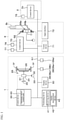
- the tractor 1 is provided with a plurality of detection devices 38, a plurality of operation members (operation devices) 39, and a control device (first control device) 60 as illustrated in FIG. 1 .
- the tractor 1 is provided with the plurality of operation members (operation devices) 39.
- the plurality of operation members 39 is a shuttle lever 39a that switches between forward and backward motion of the traveling car body 3, an ignition switch 39b that performs starting or the like of the motor 4, a PTO transmission lever 39c that sets the rotation speed of the PTO shaft, a transmission lever 39d that manually switches a transmission stage (transmission level) of the transmission device 5, an accelerator 39e that increases or decreases the vehicle speed, and the like.
- the first control device 60 has an automatic driving control unit 63 that controls automatic driving.
- the actuator 8b can change a connecting position P12 of the second connecting portion 8a2.
- the actuator 8b is, for example, a hydraulic cylinder that can extend and retract.
- One end of the actuator (hydraulic cylinder) 8b is pivotably supported, so as to be able to swing, by a bracket 47 provided to the tractor 1.
- Another end of the actuator (hydraulic cylinder) 8b is pivotably supported, so as to be able to swing, by a midway portion (intermediate portion between the first connecting portion 8a1 and the second connecting portion 8a2) of the connecting member 8a. Therefore, by extending and retracting the actuator (hydraulic cylinder) 8b, the connecting position P12 of the second connecting portion 8a2 can be changed.
- the second control device 70 is connected to an in-vehicle network N1 provided on a tractor 1 side.
- the second control device 70 can acquire tractor 1 side information—for example, detection information, the work-vehicle position (position information), and operation information.
- tractor 1 side information for example, detection information, the work-vehicle position (position information), and operation information.
- the second control device 70 can acquire via the in-vehicle network N1, for example, various information (operational information) of the work device 2 transmitted from the third control device 2a.
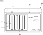
- the second control device 70 controls the connecting position P12 based on the travel line L1 of when the tractor 1 is performing automatic driving. That is, the second control device 70 changes the connecting position P12 so this connecting position P12 matches the travel line L1 at a time of automatic travel.
- the second control device 70 acquires, prior to automatic driving being started, the travel line L1 (straightaway portion L1a, turning portion L1b) via the in-vehicle network N1. Then, when automatic driving is started, the second control device 70 estimates a position of the connecting position P12 relative to the travel line L1 and changes the connecting position P12 so the estimated connecting position P12 matches the travel line L1.
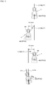
- the automatic driving control unit 63 performs a control of steering the tractor 1 leftward so the work-vehicle position P10 of the tractor 1 matches the travel line L1 (straightaway portion L1a).
- the connecting position P12 position of the work device 2 may not match the travel line L1. That is, in automatic travel of the tractor 1, when no control by the second control device 70 is performed, the connecting position P12 (position of the work device 2) may not match the travel line L1.
- the position estimation model is, for example, a learned model constructed by artificial-intelligence deep learning.
- To construct the position estimation model past performance data of when automatic driving was performed is used.
- the position estimation model can be constructed by inputting, to various computers that perform artificial-intelligence deep learning, performance data such as the work-vehicle position P10, the steering angle, the steering direction, the travel line L1, and connection information (length of the connecting member 8a, installation position of the connecting member 8a) from when automatic driving is performed.
- the position estimation model may be constructed by preparing in advance a positioning device that can position the connecting position P12, storing actual positions of the connecting position P12 positioned by the positioning device as teaching data for the connecting position P12, adding the teaching data to the performance data, and using a computer to perform deep learning.
- a configuration may be such that the connecting position P12 can be estimated by deep learning, without input of teaching data (actual positions); a construction method of the learned model is not limited.
- the second control device 70 has the above position estimation model and connection information and estimates the connecting position P12 by applying the work-vehicle position P10, the steering angle, the steering direction, the travel line L1, and the connection information to the position estimation model. Moreover, the second control device 70 extends and retracts the hydraulic cylinder 8b so the positional deviation ⁇ K1 between the estimated connecting position P12 and the travel line L1 at the time of automatic driving becomes zero—that is, in a direction of eliminating the positional deviation ⁇ K1.
- the connecting position P12 position of the work device 2 can be controlled independently of the tractor 1.
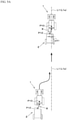
- the second control device 70 when travel of the tractor 1 starts, the second control device 70 refers to a device position P20 such as that illustrated in FIG. 7 to compute a past trajectory J2 from this device position 20 and, by comparing a current device position P20 and the past trajectory J2, monitors a current travel state of the work device 2 and a past travel state of the work device 2.
- the second control device 70 of the coupling device 8 changes the position of the connecting position P12 so the obstacle 79 is not approached, but the present invention is not limited thereto.
- the second control device 70 acquires the work-vehicle position P10, positioned by the positioning device 40, via the in-vehicle network N1 or the like.
- the second control device 70 may estimate the work-vehicle position P10 of the tractor 1 based on the connecting position P11 of the first connecting portion 8a1.
- the coupling device 8 is provided with a positioning device 77 that can position the connecting position P11 of the first connecting portion 8a1.
- the positioning device 77 can position the position (connecting position) P11 of the first connecting portion 8a1 by a global positioning system.
- the second control device 70 estimates a position of the positioning device 40 (work-vehicle position P10) by adding to and subtracting from the connecting position P11 positioned by the positioning device 77 a distance from this positioning device 77 to the positioning device 40 of the tractor 1 (distance X2 in the width direction, distance Y2 in the advancing direction). Note that even when the angle ⁇ 1 of the connecting member 8a relative to the tractor 1 changes, the second control device 70 can compute (estimate) a position corresponding to the positioning device 40—that is, the work-vehicle position P10—by correcting the distance X2 in the width direction and the distance Y2 in the advancing direction according to the angle ⁇ 1.
- the second control device 70 can change the connecting position P12 without acquiring the work-vehicle position P10 from the tractor 1.
- the device position P20 in finding the device position P20, a position positioned by the positioning device 75 is used.
- the device position P20 may be found by a positioning device 78 that can position the connecting position P12 of the second connecting portion 8a2.
- the second control device 70 can compute the device position P20 by adding and subtracting distances from the connecting position P12 positioned by the positioning device 78 to both end portions in the width direction of the work device 2 (distance XI in the width direction, distance Y1 in the advancing direction). Note that when the stroke of the hydraulic cylinder 8b changes, a position corresponding to the positioning device 40—that is, the work-vehicle position P10—can be computed (estimated) by correcting the distance XI in the width direction and the distance Y1 in the advancing direction.
- the coupling device 8 is a swing drawbar that does not raise and lower the work device 2. However, instead, this may be a raising and lowering device that raises and lowers the work device 2.
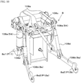
- the coupling device 8 has a lift arm 108a, a lower link 108b, a top link 108c, a lift rod 108d, and a lift cylinder 108e.
- a front end portion of the lift arm 108a is supported, so as to be able to swing, above or below an upper-rear portion of the case (transmission case) housing the transmission device 5.
- the lift arm 108a swings (is raised and lowered) by being driven by the lift cylinder 108e.
- the lift cylinder 108e is constituted from a hydraulic cylinder.
- the lift cylinder 108e is connected to a hydraulic pump via a control valve 34.
- the control valve 34 is an electromagnetic valve or the like and extends and retracts the lift cylinder 108e.
- a front end portion of the lower link 108b is supported, so as to be able to swing, above or below a lower-rear portion of the transmission device 5.
- a front end portion of the top link 108c is supported, so as to be able to swing, above or below a rear portion of the transmission device 5, above the lower link 108b.
- the lift rod 108d connects the lift arm 108a and the lower link 108b.
- the work device 2 is connected to a rear portion of the lower link 108b and a rear portion of the top link 108c.
- At least one among a lift rod 108d on a left side and a lift rod 108d on a right side is constituted by a hydraulic cylinder that can extend and retract.
- a hydraulic cylinder that can extend and retract.
- the lift rod 108d on the left side—or the lift rod 108d on the right side—constituted by the hydraulic cylinder in a state wherein the lift cylinder 108e is not extended and retracted a relative position of a distal end of a lower link 108b on the left side and a distal end of a lower link 108b on the right side can be adjusted.
- the lower link 108b on the right side is constituted by a hydraulic cylinder.
- the lower link 108b on the left side may be constituted by a hydraulic cylinder.
- the lower link 108b corresponds to the connecting member 8a
- the distal end (rear end) of the lower link 108b corresponds to the second connecting portion 8a2
- a proximal end (front end) of the lower link 108b corresponds to the first connecting portion 8a1.
- a connecting position corresponding to the second connecting portion 8a2 of the distal end of the lower link 108b on the left side may be referred to as a "left connecting position P12a”
- a connecting position corresponding to the second connecting portion 8a2 of the distal end of the lower link 108b on the right side may be referred to as a "right connecting position P12b".
- the lift cylinder 108e and the lift rod 108d on the right side constituted by the hydraulic cylinder correspond to the hydraulic cylinder 8b.
- FIG. 11 illustrates a control block diagram of the tractor 1, the coupling device 8, and the work device 2 in a variation.
- the coupling device 8 is provided with a control valve 155A that controls the lift cylinder 108e (hydraulic cylinder 8b) and a control valve 155B that controls the lift rod 108d on the right side (hydraulic cylinder 8b).
- the control valves 155A, 155B are, for example, an electromagnetic valve that can switch between three positions.
- the second control device 70 extends and retracts the lift cylinder 108e (hydraulic cylinder 8b) by outputting a control signal to a solenoid of the control valve 155A.
- the lift cylinder 108e hydroaulic cylinder 8b
- the lift rod 108d on the left side and the lift rod 108d on the right side are raised.
- the connecting positions P12a, P12b of the second connecting portion 8a2 also move upward.
- the lift cylinder 108e (hydraulic cylinder 8b) is extended, the lift rod 108d on the left side and the lift rod 108d on the right side are lowered. In conjunction with this lowering, the connecting positions P12a, P12b of the second connecting portion 8a2 also move downward.
- the second control device 70 extends and retracts the lift rod 108d on the right side (hydraulic cylinder 8b) by outputting a control signal to a solenoid of the control valve 155B.
- a solenoid of the control valve 155B For example, when the lift rod 108d on the right side (hydraulic cylinder 8b) is retracted, the lift rod 108d on the right side is raised. In conjunction with this raising, the right connecting position P12b also moves upward. When the lift rod 108d on the right side (hydraulic cylinder 8b) is extended, the lift rod 108d on the right side is lowered. In conjunction with this lowering, the right connecting position P12b also moves downward.
- the second control device 70 monitors the inclination of the work device 2.
- the inclination of the work device 2 can be understood from a change in the left connecting position P12a.
- the second control device 70 determines that the work device 2 is held horizontally when the left connecting position P12a in the vertical direction is the same as the right connecting position P12b in the vertical direction.
- the second control device 70 determines that the work device 2 is inclined to the right in the width direction (rightwardly descending incline) when the left connecting position P12a is positioned above the right connecting position P12b. Moreover, the second control device 70 determines that the work device 2 is inclined to the left in the width direction (leftwardly descending incline) when the left connecting position P12a is positioned below the right connecting position P12b.
- the left connecting position P12a can be found by, for example, installing a position detection sensor 110 (inclination sensor, acceleration sensor, or the like) on a distal-end side of the lift rod 108d on the left side and having the second control device 70 convert a detection value of the position detection sensor 110 into the left connecting position P12a.
- a position detection sensor 110 inclination sensor, acceleration sensor, or the like
- the coupling device 8 may be provided with an environment measurement device 80 that measures an environment surrounding the tractor 1 or the work device 2.
- the environment measurement device 80 is a device that measures wind speed, wind direction, temperature, and the like.
- the second control device 70 changes the left connecting position P12a and the right connecting position P12b of the coupling device 8 based at least on environment information (wind speed, wind direction, temperature) measured by the environment measurement device 80.
- the second control device 70 has a work optimization model for determining optimal work in response to environmental changes.
- the work optimization model is a learned model constructed by artificial-intelligence deep learning. To construct the work optimization model, work data from when work was performed in the past is used.
- the work optimization model can be constructed by inputting, to various computers that perform artificial-intelligence deep learning, work data such as environmental information (wind speed, wind direction, temperature) from when work was performed, the attitude of the work device 2 (left connecting position P12a, right connecting position 12b), a height of the work device 2 (stroke of the lift cylinder 108e), and a type of the work device 2.
- the height of the work device 2 can be obtained by installing a stroke sensor 112 that detects the stroke of the lift cylinder 108e and having the second control device 70 convert a detection value of the stroke sensor 112 into the height of the work device 2.
- the type of the work device 2 can be obtained from any among an external device, the tractor 1, and the work device 2.
- the second control device 70 applies the environment information measured by the environment measurement device 80, the attitude of the work device 2 (left connecting position P12a, right connecting position 12b), the height of the work device 2 (stroke of the lift cylinder 108e), and the type of the work device 2 to the work optimization model.
- work when the work device 2 is inclined due to an inclination of the field, work can be performed by correcting the inclination of the work device 2 to an optimal inclination, regardless of the inclination of the field.
- the coupling device 8 is described as changing the connecting positions P12, P12a, 12b of the second connecting portion 8a2.
- the coupling device 8 may change the position of the connecting position P11 of the first connecting portion 8a1. That is, by replacing "connecting position P12" with "connecting position P11" in the above embodiments, it is possible to change the position of the connecting position P11 by the second control device 70 according to automatic travel and the travel performance.
- the coupling device 8 controls the connecting positions P11, P12 based on the travel line L1 of the work vehicle 1. Accordingly, when, for example, performing automatic driving, automatic steering, or the like along the travel line L1, the work device 2 can be positioned to follow this travel line L1. That is, regardless of whether the work vehicle 1 matches the travel line L1, the work device 2 can be made to follow the travel line L1, and work along the travel line L1 can be performed.
- the coupling device 8 controls the connecting positions P11, P12 based on the work-vehicle position P10 of the work vehicle 1 and the travel line L1 of the work vehicle 1. Moreover, when the deviation between the work-vehicle position P10 and the travel line L1 is no less than the threshold, the coupling device 8 changes the connecting positions P11, P12 in the direction of eliminating the deviation. Accordingly, when the work-vehicle position P10 of the work vehicle 1 is shifted from the travel line L1 (the deviation is no less than the threshold), at least the work device 2 can be made to approach the travel line L1.
- the connecting positions P11, P12 are controlled so the attitude falls within the threshold. Accordingly, the attitude of the work device 2 can be held to be constant, and work can be performed in a stable attitude.
- the coupling device 8 controls the connecting positions P11, P12 based on the environment surrounding the work vehicle 1 or the work device 2. Accordingly, when, for example, the work device 2 is a work device 2 of a spreading type, spreading work suited to the environment can be performed.
- the coupling device 8 estimates the work-vehicle position P10 of the work vehicle 1 based on the connecting positions P11, P12 of the first connecting portion 8a1. Accordingly, even if the coupling device 8 does not acquire the work-vehicle position P10 from the work vehicle 1, this work-vehicle position P10 can be acquired, and, for example, the connecting positions P11, P12 can be adjusted by considering the estimated work-vehicle position P10.
- the coupling device 8 estimates the device position P20 of the work device 2 based on the connecting positions P11, P12 of the second connecting portion 8a2. Accordingly, the device position P20 can be obtained even if the coupling device 8 does not acquire the device position P20 from the work device 2, and, for example, the connecting positions P11, P12 can be adjusted by considering the obtained device position P20.
- the coupling device 8 has a global positioning system. Accordingly, the position of this coupling device 8 can be understood independently of the work vehicle 1 and the work device 2.
Landscapes
- Life Sciences & Earth Sciences (AREA)
- Engineering & Computer Science (AREA)
- Mechanical Engineering (AREA)
- Soil Sciences (AREA)
- Environmental Sciences (AREA)
- Zoology (AREA)
- Agricultural Machines (AREA)
- Lifting Devices For Agricultural Implements (AREA)
- Guiding Agricultural Machines (AREA)
- Details Of Connecting Devices For Male And Female Coupling (AREA)
- Control Of Position, Course, Altitude, Or Attitude Of Moving Bodies (AREA)
Applications Claiming Priority (1)
| Application Number | Priority Date | Filing Date | Title |
|---|---|---|---|
| JP2020155566A JP7421454B2 (ja) | 2020-09-16 | 2020-09-16 | 連結装置 |
Publications (3)
| Publication Number | Publication Date |
|---|---|
| EP3970464A2 true EP3970464A2 (de) | 2022-03-23 |
| EP3970464A3 EP3970464A3 (de) | 2022-06-08 |
| EP3970464B1 EP3970464B1 (de) | 2025-01-01 |
Family
ID=77666182
Family Applications (1)
| Application Number | Title | Priority Date | Filing Date |
|---|---|---|---|
| EP21195206.4A Active EP3970464B1 (de) | 2020-09-16 | 2021-09-07 | Kopplungsvorrichtung |
Country Status (3)
| Country | Link |
|---|---|
| US (1) | US12102023B2 (de) |
| EP (1) | EP3970464B1 (de) |
| JP (2) | JP7421454B2 (de) |
Families Citing this family (3)
| Publication number | Priority date | Publication date | Assignee | Title |
|---|---|---|---|---|
| US12466350B2 (en) | 2022-07-28 | 2025-11-11 | Kubota Corporation | Audio signaling system and method for autonomous vehicles |
| JP7795723B2 (ja) * | 2022-07-29 | 2026-01-08 | 井関農機株式会社 | 作業車両 |
| US12349616B2 (en) | 2023-01-09 | 2025-07-08 | Kubota Corporation | Implement automation system |
Citations (1)
| Publication number | Priority date | Publication date | Assignee | Title |
|---|---|---|---|---|
| JP2014064582A (ja) | 2013-11-27 | 2014-04-17 | Kubota Corp | 作業機連結装置 |
Family Cites Families (4)
| Publication number | Priority date | Publication date | Assignee | Title |
|---|---|---|---|---|
| US7162348B2 (en) | 2002-12-11 | 2007-01-09 | Hemisphere Gps Llc | Articulated equipment position control system and method |
| US7054731B1 (en) * | 2003-08-29 | 2006-05-30 | Trimble Navigation Limited | Farm implement guidance method and apparatus |
| US8256526B2 (en) | 2008-07-08 | 2012-09-04 | A.I.L., Inc. | Apparatus and a system for providing guidance control for pull type tongued implements |
| US20100198444A1 (en) | 2009-02-03 | 2010-08-05 | Thurston Manufacturing Company | Intermediate pivot device for positioning a pulled implement |
-
2020
- 2020-09-16 JP JP2020155566A patent/JP7421454B2/ja active Active
-
2021
- 2021-09-01 US US17/463,804 patent/US12102023B2/en active Active
- 2021-09-07 EP EP21195206.4A patent/EP3970464B1/de active Active
-
2024
- 2024-01-12 JP JP2024003009A patent/JP7823090B2/ja active Active
Patent Citations (1)
| Publication number | Priority date | Publication date | Assignee | Title |
|---|---|---|---|---|
| JP2014064582A (ja) | 2013-11-27 | 2014-04-17 | Kubota Corp | 作業機連結装置 |
Also Published As
| Publication number | Publication date |
|---|---|
| JP7421454B2 (ja) | 2024-01-24 |
| JP2024038359A (ja) | 2024-03-19 |
| EP3970464B1 (de) | 2025-01-01 |
| US20220078960A1 (en) | 2022-03-17 |
| EP3970464A3 (de) | 2022-06-08 |
| US12102023B2 (en) | 2024-10-01 |
| JP7823090B2 (ja) | 2026-03-03 |
| JP2022049381A (ja) | 2022-03-29 |
Similar Documents
| Publication | Publication Date | Title |
|---|---|---|
| AU2020343982B2 (en) | Agricultural machine | |
| JP7823090B2 (ja) | 連結装置の制御方法 | |
| JP6643094B2 (ja) | 圃場作業車両 | |
| KR102553109B1 (ko) | 작업차 | |
| US20180319392A1 (en) | Obstacle detection system for a work vehicle | |
| JP2022125058A (ja) | 作業車両 | |
| CN113044050B (zh) | 作业车辆以及作业车辆的行驶管理系统 | |
| JP2022104737A (ja) | 無人飛行体及び農業支援システム | |
| EP3254547A1 (de) | System und verfahren zur fahrzeuglenkungskalibrierung | |
| EP4026415B1 (de) | Arbeitsfahrzeug und arbeitshilfsvorrichtung für arbeitsfahrzeug | |
| WO2022145410A1 (ja) | 農業支援システム、及び無人飛行体 | |
| US12369508B2 (en) | Travel line creation system for agricultural machine | |
| JP7830485B2 (ja) | 農業支援システム | |
| US20210191427A1 (en) | System and method for stabilized teleoperations of vehicles | |
| JP2023001180A (ja) | 圃場作業車両 | |
| US12490664B2 (en) | Turning control for autonomous agricultural vehicle | |
| JP7269554B2 (ja) | 作業車両 | |
| JP7330878B2 (ja) | 作業機 | |
| JP2024142696A (ja) | 作業車両の制御方法、作業車両用制御プログラム、作業車両用制御システム及び作業システム | |
| JP7532246B2 (ja) | 農業支援システム | |
| JP7443209B2 (ja) | 自動運転支援装置 | |
| JP7179565B2 (ja) | 作業車両 | |
| JP2022104739A (ja) | 農業支援システム | |
| US20260120478A1 (en) | Working vehicle and traveling management system | |
| JP7490553B2 (ja) | 農業支援システム |
Legal Events
| Date | Code | Title | Description |
|---|---|---|---|
| PUAI | Public reference made under article 153(3) epc to a published international application that has entered the european phase |
Free format text: ORIGINAL CODE: 0009012 |
|
| STAA | Information on the status of an ep patent application or granted ep patent |
Free format text: STATUS: THE APPLICATION HAS BEEN PUBLISHED |
|
| AK | Designated contracting states |
Kind code of ref document: A2 Designated state(s): AL AT BE BG CH CY CZ DE DK EE ES FI FR GB GR HR HU IE IS IT LI LT LU LV MC MK MT NL NO PL PT RO RS SE SI SK SM TR |
|
| PUAL | Search report despatched |
Free format text: ORIGINAL CODE: 0009013 |
|
| AK | Designated contracting states |
Kind code of ref document: A3 Designated state(s): AL AT BE BG CH CY CZ DE DK EE ES FI FR GB GR HR HU IE IS IT LI LT LU LV MC MK MT NL NO PL PT RO RS SE SI SK SM TR |
|
| RIC1 | Information provided on ipc code assigned before grant |
Ipc: A01B 69/00 20060101AFI20220502BHEP |
|
| STAA | Information on the status of an ep patent application or granted ep patent |
Free format text: STATUS: REQUEST FOR EXAMINATION WAS MADE |
|
| 17P | Request for examination filed |
Effective date: 20221121 |
|
| RBV | Designated contracting states (corrected) |
Designated state(s): AL AT BE BG CH CY CZ DE DK EE ES FI FR GB GR HR HU IE IS IT LI LT LU LV MC MK MT NL NO PL PT RO RS SE SI SK SM TR |
|
| STAA | Information on the status of an ep patent application or granted ep patent |
Free format text: STATUS: EXAMINATION IS IN PROGRESS |
|
| 17Q | First examination report despatched |
Effective date: 20240404 |
|
| REG | Reference to a national code |
Ref legal event code: R079 Ipc: A01B0059060000 Ref country code: DE Ref legal event code: R079 Ref document number: 602021024139 Country of ref document: DE Free format text: PREVIOUS MAIN CLASS: A01B0069000000 Ipc: A01B0059060000 |
|
| GRAP | Despatch of communication of intention to grant a patent |
Free format text: ORIGINAL CODE: EPIDOSNIGR1 |
|
| STAA | Information on the status of an ep patent application or granted ep patent |
Free format text: STATUS: GRANT OF PATENT IS INTENDED |
|
| RIC1 | Information provided on ipc code assigned before grant |
Ipc: A01B 69/00 20060101ALI20240719BHEP Ipc: A01B 63/111 20060101ALI20240719BHEP Ipc: A01B 59/06 20060101AFI20240719BHEP |
|
| INTG | Intention to grant announced |
Effective date: 20240805 |
|
| GRAS | Grant fee paid |
Free format text: ORIGINAL CODE: EPIDOSNIGR3 |
|
| GRAA | (expected) grant |
Free format text: ORIGINAL CODE: 0009210 |
|
| STAA | Information on the status of an ep patent application or granted ep patent |
Free format text: STATUS: THE PATENT HAS BEEN GRANTED |
|
| AK | Designated contracting states |
Kind code of ref document: B1 Designated state(s): AL AT BE BG CH CY CZ DE DK EE ES FI FR GB GR HR HU IE IS IT LI LT LU LV MC MK MT NL NO PL PT RO RS SE SI SK SM TR |
|
| REG | Reference to a national code |
Ref country code: GB Ref legal event code: FG4D |
|
| REG | Reference to a national code |
Ref country code: DE Ref legal event code: R096 Ref document number: 602021024139 Country of ref document: DE |
|
| REG | Reference to a national code |
Ref country code: CH Ref legal event code: EP |
|
| REG | Reference to a national code |
Ref country code: IE Ref legal event code: FG4D |
|
| REG | Reference to a national code |
Ref country code: LT Ref legal event code: MG9D |
|
| REG | Reference to a national code |
Ref country code: NL Ref legal event code: MP Effective date: 20250101 |
|
| REG | Reference to a national code |
Ref country code: AT Ref legal event code: MK05 Ref document number: 1755268 Country of ref document: AT Kind code of ref document: T Effective date: 20250101 |
|
| PG25 | Lapsed in a contracting state [announced via postgrant information from national office to epo] |
Ref country code: NL Free format text: LAPSE BECAUSE OF FAILURE TO SUBMIT A TRANSLATION OF THE DESCRIPTION OR TO PAY THE FEE WITHIN THE PRESCRIBED TIME-LIMIT Effective date: 20250101 |
|
| PG25 | Lapsed in a contracting state [announced via postgrant information from national office to epo] |
Ref country code: FI Free format text: LAPSE BECAUSE OF FAILURE TO SUBMIT A TRANSLATION OF THE DESCRIPTION OR TO PAY THE FEE WITHIN THE PRESCRIBED TIME-LIMIT Effective date: 20250101 |
|
| PG25 | Lapsed in a contracting state [announced via postgrant information from national office to epo] |
Ref country code: PL Free format text: LAPSE BECAUSE OF FAILURE TO SUBMIT A TRANSLATION OF THE DESCRIPTION OR TO PAY THE FEE WITHIN THE PRESCRIBED TIME-LIMIT Effective date: 20250101 |
|
| PG25 | Lapsed in a contracting state [announced via postgrant information from national office to epo] |
Ref country code: ES Free format text: LAPSE BECAUSE OF FAILURE TO SUBMIT A TRANSLATION OF THE DESCRIPTION OR TO PAY THE FEE WITHIN THE PRESCRIBED TIME-LIMIT Effective date: 20250101 |
|
| PG25 | Lapsed in a contracting state [announced via postgrant information from national office to epo] |
Ref country code: NO Free format text: LAPSE BECAUSE OF FAILURE TO SUBMIT A TRANSLATION OF THE DESCRIPTION OR TO PAY THE FEE WITHIN THE PRESCRIBED TIME-LIMIT Effective date: 20250401 Ref country code: IS Free format text: LAPSE BECAUSE OF FAILURE TO SUBMIT A TRANSLATION OF THE DESCRIPTION OR TO PAY THE FEE WITHIN THE PRESCRIBED TIME-LIMIT Effective date: 20250501 |
|
| PG25 | Lapsed in a contracting state [announced via postgrant information from national office to epo] |
Ref country code: HR Free format text: LAPSE BECAUSE OF FAILURE TO SUBMIT A TRANSLATION OF THE DESCRIPTION OR TO PAY THE FEE WITHIN THE PRESCRIBED TIME-LIMIT Effective date: 20250101 |
|
| PG25 | Lapsed in a contracting state [announced via postgrant information from national office to epo] |
Ref country code: PT Free format text: LAPSE BECAUSE OF FAILURE TO SUBMIT A TRANSLATION OF THE DESCRIPTION OR TO PAY THE FEE WITHIN THE PRESCRIBED TIME-LIMIT Effective date: 20250502 Ref country code: LV Free format text: LAPSE BECAUSE OF FAILURE TO SUBMIT A TRANSLATION OF THE DESCRIPTION OR TO PAY THE FEE WITHIN THE PRESCRIBED TIME-LIMIT Effective date: 20250101 |
|
| PG25 | Lapsed in a contracting state [announced via postgrant information from national office to epo] |
Ref country code: GR Free format text: LAPSE BECAUSE OF FAILURE TO SUBMIT A TRANSLATION OF THE DESCRIPTION OR TO PAY THE FEE WITHIN THE PRESCRIBED TIME-LIMIT Effective date: 20250402 Ref country code: BG Free format text: LAPSE BECAUSE OF FAILURE TO SUBMIT A TRANSLATION OF THE DESCRIPTION OR TO PAY THE FEE WITHIN THE PRESCRIBED TIME-LIMIT Effective date: 20250101 |
|
| PG25 | Lapsed in a contracting state [announced via postgrant information from national office to epo] |
Ref country code: AT Free format text: LAPSE BECAUSE OF FAILURE TO SUBMIT A TRANSLATION OF THE DESCRIPTION OR TO PAY THE FEE WITHIN THE PRESCRIBED TIME-LIMIT Effective date: 20250101 |
|
| PG25 | Lapsed in a contracting state [announced via postgrant information from national office to epo] |
Ref country code: CZ Free format text: LAPSE BECAUSE OF FAILURE TO SUBMIT A TRANSLATION OF THE DESCRIPTION OR TO PAY THE FEE WITHIN THE PRESCRIBED TIME-LIMIT Effective date: 20250101 |
|
| PG25 | Lapsed in a contracting state [announced via postgrant information from national office to epo] |
Ref country code: SE Free format text: LAPSE BECAUSE OF FAILURE TO SUBMIT A TRANSLATION OF THE DESCRIPTION OR TO PAY THE FEE WITHIN THE PRESCRIBED TIME-LIMIT Effective date: 20250101 |
|
| REG | Reference to a national code |
Ref country code: DE Ref legal event code: R097 Ref document number: 602021024139 Country of ref document: DE |
|
| PG25 | Lapsed in a contracting state [announced via postgrant information from national office to epo] |
Ref country code: SM Free format text: LAPSE BECAUSE OF FAILURE TO SUBMIT A TRANSLATION OF THE DESCRIPTION OR TO PAY THE FEE WITHIN THE PRESCRIBED TIME-LIMIT Effective date: 20250101 |
|
| PG25 | Lapsed in a contracting state [announced via postgrant information from national office to epo] |
Ref country code: DK Free format text: LAPSE BECAUSE OF FAILURE TO SUBMIT A TRANSLATION OF THE DESCRIPTION OR TO PAY THE FEE WITHIN THE PRESCRIBED TIME-LIMIT Effective date: 20250101 |
|
| PGFP | Annual fee paid to national office [announced via postgrant information from national office to epo] |
Ref country code: DE Payment date: 20250730 Year of fee payment: 5 |
|
| PG25 | Lapsed in a contracting state [announced via postgrant information from national office to epo] |
Ref country code: IT Free format text: LAPSE BECAUSE OF FAILURE TO SUBMIT A TRANSLATION OF THE DESCRIPTION OR TO PAY THE FEE WITHIN THE PRESCRIBED TIME-LIMIT Effective date: 20250101 |
|
| PGFP | Annual fee paid to national office [announced via postgrant information from national office to epo] |
Ref country code: FR Payment date: 20250808 Year of fee payment: 5 |
|
| PG25 | Lapsed in a contracting state [announced via postgrant information from national office to epo] |
Ref country code: EE Free format text: LAPSE BECAUSE OF FAILURE TO SUBMIT A TRANSLATION OF THE DESCRIPTION OR TO PAY THE FEE WITHIN THE PRESCRIBED TIME-LIMIT Effective date: 20250101 |
|
| PG25 | Lapsed in a contracting state [announced via postgrant information from national office to epo] |
Ref country code: RO Free format text: LAPSE BECAUSE OF FAILURE TO SUBMIT A TRANSLATION OF THE DESCRIPTION OR TO PAY THE FEE WITHIN THE PRESCRIBED TIME-LIMIT Effective date: 20250101 |
|
| PG25 | Lapsed in a contracting state [announced via postgrant information from national office to epo] |
Ref country code: SK Free format text: LAPSE BECAUSE OF FAILURE TO SUBMIT A TRANSLATION OF THE DESCRIPTION OR TO PAY THE FEE WITHIN THE PRESCRIBED TIME-LIMIT Effective date: 20250101 |
|
| PLBE | No opposition filed within time limit |
Free format text: ORIGINAL CODE: 0009261 |
|
| STAA | Information on the status of an ep patent application or granted ep patent |
Free format text: STATUS: NO OPPOSITION FILED WITHIN TIME LIMIT |
|
| REG | Reference to a national code |
Ref country code: CH Ref legal event code: L10 Free format text: ST27 STATUS EVENT CODE: U-0-0-L10-L00 (AS PROVIDED BY THE NATIONAL OFFICE) Effective date: 20251112 |
|
| 26N | No opposition filed |
Effective date: 20251002 |
|
| REG | Reference to a national code |
Ref country code: CH Ref legal event code: H13 Free format text: ST27 STATUS EVENT CODE: U-0-0-H10-H13 (AS PROVIDED BY THE NATIONAL OFFICE) Effective date: 20260504 |