EP3970453B1 - Shared power topology for led luminaires - Google Patents
Shared power topology for led luminaires Download PDFInfo
- Publication number
- EP3970453B1 EP3970453B1 EP20726122.3A EP20726122A EP3970453B1 EP 3970453 B1 EP3970453 B1 EP 3970453B1 EP 20726122 A EP20726122 A EP 20726122A EP 3970453 B1 EP3970453 B1 EP 3970453B1
- Authority
- EP
- European Patent Office
- Prior art keywords
- led
- driver
- string
- electrically connected
- led string
- Prior art date
- Legal status (The legal status is an assumption and is not a legal conclusion. Google has not performed a legal analysis and makes no representation as to the accuracy of the status listed.)
- Active
Links
Images


Classifications
-
- H—ELECTRICITY
- H05—ELECTRIC TECHNIQUES NOT OTHERWISE PROVIDED FOR
- H05B—ELECTRIC HEATING; ELECTRIC LIGHT SOURCES NOT OTHERWISE PROVIDED FOR; CIRCUIT ARRANGEMENTS FOR ELECTRIC LIGHT SOURCES, IN GENERAL
- H05B45/00—Circuit arrangements for operating light-emitting diodes [LED]
- H05B45/50—Circuit arrangements for operating light-emitting diodes [LED] responsive to malfunctions or undesirable behaviour of LEDs; responsive to LED life; Protective circuits
- H05B45/52—Circuit arrangements for operating light-emitting diodes [LED] responsive to malfunctions or undesirable behaviour of LEDs; responsive to LED life; Protective circuits in a parallel array of LEDs
-
- H—ELECTRICITY
- H05—ELECTRIC TECHNIQUES NOT OTHERWISE PROVIDED FOR
- H05B—ELECTRIC HEATING; ELECTRIC LIGHT SOURCES NOT OTHERWISE PROVIDED FOR; CIRCUIT ARRANGEMENTS FOR ELECTRIC LIGHT SOURCES, IN GENERAL
- H05B45/00—Circuit arrangements for operating light-emitting diodes [LED]
- H05B45/30—Driver circuits
- H05B45/37—Converter circuits
-
- H—ELECTRICITY
- H05—ELECTRIC TECHNIQUES NOT OTHERWISE PROVIDED FOR
- H05B—ELECTRIC HEATING; ELECTRIC LIGHT SOURCES NOT OTHERWISE PROVIDED FOR; CIRCUIT ARRANGEMENTS FOR ELECTRIC LIGHT SOURCES, IN GENERAL
- H05B45/00—Circuit arrangements for operating light-emitting diodes [LED]
- H05B45/10—Controlling the intensity of the light
-
- H—ELECTRICITY
- H05—ELECTRIC TECHNIQUES NOT OTHERWISE PROVIDED FOR
- H05B—ELECTRIC HEATING; ELECTRIC LIGHT SOURCES NOT OTHERWISE PROVIDED FOR; CIRCUIT ARRANGEMENTS FOR ELECTRIC LIGHT SOURCES, IN GENERAL
- H05B45/00—Circuit arrangements for operating light-emitting diodes [LED]
- H05B45/40—Details of LED load circuits
- H05B45/44—Details of LED load circuits with an active control inside an LED matrix
- H05B45/48—Details of LED load circuits with an active control inside an LED matrix having LEDs organised in strings and incorporating parallel shunting devices
-
- H—ELECTRICITY
- H05—ELECTRIC TECHNIQUES NOT OTHERWISE PROVIDED FOR
- H05B—ELECTRIC HEATING; ELECTRIC LIGHT SOURCES NOT OTHERWISE PROVIDED FOR; CIRCUIT ARRANGEMENTS FOR ELECTRIC LIGHT SOURCES, IN GENERAL
- H05B45/00—Circuit arrangements for operating light-emitting diodes [LED]
- H05B45/50—Circuit arrangements for operating light-emitting diodes [LED] responsive to malfunctions or undesirable behaviour of LEDs; responsive to LED life; Protective circuits
-
- H—ELECTRICITY
- H05—ELECTRIC TECHNIQUES NOT OTHERWISE PROVIDED FOR
- H05B—ELECTRIC HEATING; ELECTRIC LIGHT SOURCES NOT OTHERWISE PROVIDED FOR; CIRCUIT ARRANGEMENTS FOR ELECTRIC LIGHT SOURCES, IN GENERAL
- H05B45/00—Circuit arrangements for operating light-emitting diodes [LED]
- H05B45/40—Details of LED load circuits
- H05B45/44—Details of LED load circuits with an active control inside an LED matrix
- H05B45/46—Details of LED load circuits with an active control inside an LED matrix having LEDs disposed in parallel lines
Definitions
- LED luminaires typically include an LED source or multiple sets of LEDs connected together. LEDs are typically designed to run on low voltage, such as 12-24V, direct current (DC) electricity. For this reason, LED luminaires will have one or more LED drivers. LED drivers, which are sometimes also referred to as LED power supplies, are circuits that convert power from a relatively higher line voltage (such as 120V or 220V) alternating current (AC) source into low voltage direct current. In addition to rectifying AC current to DC current, LED drivers protect LEDs from current and voltage fluctuations caused by variabilities in the power source. LED drivers may be integral with an LED luminaire, or they may be external to the luminaire and electrically connected between an external power supply and the LEDs.
- DC direct current
- multiple drivers are needed to provide power to multiple LED strings or sources.
- failure of that driver causes a corresponding failure of the driver's associated LED source or string.
- a system for emitting light includes a first light emitting diode (LED) string of one or more LEDs that are electrically connected in series, and also a first LED driver that is electrically connected in parallel to the first LED string.
- the system also includes a first one-way conductor having an input that that is electrically connected to an output of the first LED driver, and an output that is electrically connected to an input of the first LED string.
- the system also includes a second LED driver that is electrically connected in parallel to the first LED string.
- the system also includes a second one-way conductor having an input that that is electrically connected to an output of the second LED driver, along with an output that is electrically connected to an input of the first LED string.
- the system includes a second LED string of one or more LEDs that are electrically connected in series. If so, the second LED string will be electrically connected in parallel to each of the first LED string, the first LED driver, and the second LED driver.
- a switch may be electrically connected between the inputs of the first LED string and the second LED string, The switch will be configured to: (i) when neither of the LED drivers is failing, open a first electrical connection between the first LED driver and the second LED string, and open a second electrical connection between the second LED driver and the first LED string; and (ii) when either the first or the second LED driver is failing, close the first and second electrical connections.
- the system for emitting light includes a first LED string of one or more LEDs that are electrically connected in series, a first LED driver that is electrically connected in parallel to the first LED string, and a first one-way conductor.
- the first one-way conductor includes an input that that is electrically connected to an output of the first LED driver, and an output that is electrically connected to an input of the first LED string.
- the system also includes a second LED string of one or more LEDs that are electrically connected in series, a second LED driver that is electrically connected in parallel to the second LED string, and a second one-way conductor.
- the second one-way conductor includes an input that that is electrically connected to an output of the second LED driver, and an output that is electrically connected to an input of the second LED string.
- a switch in this example a normally-open switch, is electrically connected between the inputs of the first LED string and the second LED string. When neither of the LED drivers is failing, the normally-open switch will not electrically connect the first LED driver to the second LED string, nor will it electrically connect the second LED driver to the first LED string. When either the first or the second LED driver is failing, the normally-open switch will close and both LED strings will be pulled in parallel and driven by the non-failing driver.
- a system for emitting light includes: a first LED string of one or more LEDs that are electrically connected in series; a first LED driver that is electrically connected in parallel to the first LED string; and a first voltage sensor positioned to measure voltage in a conductive path between the first LED driver and the first LED string.
- the system also includes: a second LED string of one or more LEDs that are electrically connected in series; a second LED driver that is electrically connected in parallel to the second LED string; and a second voltage sensor positioned to measure voltage in a conductive path between the first LED driver and the first LED string.
- the system also includes a first switch, preferably a normally open switch, that is configured to close and positioned to create a conductive path between the first LED driver and the second LED string when the voltage measured by the first voltage sensor is more than a threshold level above the voltage measured by the second voltage sensor.
- the system also includes a second switch, preferably a normally open switch, that is configured to close and positioned to create a conductive path between the second LED driver and the first LED string when the voltage measured by the second voltage sensor is more than a threshold level above the voltage measured by the first voltage sensor.
- each of the normally open switches may include a field effect transistor.
- each of the one-way conductors may include, for example, a field effect transistor or a diode.
- the LED string(s) may be components of an LED luminaire.
- the LED drivers also may be components of the LED luminaire, or the LED drivers may be positioned external to the LED luminaire.
- a first current sensor may be positioned to detect current in a conductive path between the first LED driver and the first LED string, and a second current sensor may be positioned to detect current in a conductive path between the second LED driver and the second LED string. If so, each of the current sensors may trigger closure of the normally-open switch upon detection of an undercurrent condition.
- the system may include an optical sensor that is configured to measure brightness of light emitted by one or more of the LED strings.
- the optical sensor may be configured to trigger closure of the normally-open switch upon detection that an LED string's brightness is lower than a threshold level.
- the system may include a temperature sensor that is configured to measure temperature in a vicinity of one or more of the LED strings.
- the temperature sensor may be configured to trigger closure of the normally-open switch upon detection that the temperature that is lower than a threshold level.
- the invention is defined by the subject-matter of claim 1.
- US2008295371 discloses an emergency exit-light which powers an emergency LED array upon failure of the mains.
- the terms "lighting device,” “light fixture,” “luminaire” and “illumination device” are used interchangeably to refer to a device that includes a source of optical radiation such as one or more light emitting diodes (LEDs), light bulbs, ultraviolet light or infrared sources, or other sources of optical radiation.
- a lighting device will also include a housing, one or more electrical components for conveying power from a power supply to the device's optical radiation source, and optionally control circuitry.
- An “LED luminaire” is a lighting device that includes LEDs as an optical radiation source.
- the term "electrically connected” means, with respect to two or more components, that a conductive path exists between the components so that electric current can flow from one of the components to the other, either directly or through one or more intermediary components.
- an example lighting device 101 such as that which may exist in the prior art may include an optical radiation source, such as any number of lighting modules that include LEDs.
- lighting device 101 will include a number of LED modules 103, 105 sufficient to provide a high intensity LED device.
- the lighting device 101 may include a housing 107 that holds electrical components such as a fixture controller, a power source, and wiring and circuitry to supply power and/or control signals to the LED modules.
- the lighting device 101 also may include communication components 108 such as a transceiver and antenna.
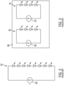
- Fig. 2 illustrates a common topology for LED drivers of an LED luminaire as may exist in the prior art.
- an LED string 201 includes any number of LEDs electrically connected to each other in series.
- An LED driver 202 is electrically connected in parallel to the LED string 201 to provide power to the LED string 201.
- An example LED driver is disclosed in U.S. patent number 7,075,252 ("LED Driver Circuit"), the disclosure of which is incorporated into this document by reference.
- Fig. 3 illustrates that in the prior art, an LED luminaire (represented by box 305) may include multiple LED strings 301, 311, each of which is powered by its own independently associated LED driver 302, 312.
- a problem with this topology is that when a driver 302 fails, all of the LEDs in its associated LED string 301 will lose power and will go dark.
- LED drivers have a limited lifespan and eventually need to be replaced.
- all LED luminaires that include the driver circuit topology shown in Fig. 3 will eventually require maintenance to replace LED drivers that have reached end-of-life.
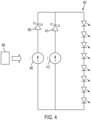
- Fig. 4 illustrates an example LED driver circuit topology that helps address the problems described above.
- an LED string 401 is electrically connected to two or more LED drivers 402, 412.
- the LED drivers may be of either the constant current type or the constant voltage type, although if the driver is of the constant voltage type it may have additional circuitry that causes it to have a constant current.
- the brightness of the LEDs is controlled by an external controller 409 that includes a processor and an output that directs a signal to each driver which causes the amplitude of the current to vary, or that causes the brightness of the emitted light to dim due to pulse width modulation.
- Each LED driver will generate an output current that is responsive to the signal of the controller.
- the brightness of the LEDs in the LED string 401 will vary with amplitude of the output current.
- the LED drivers 402, 412 are electrically connected to the LED string 401 in parallel so that if one of the LED drivers (such as 402) fails, the other LED driver (in this example, 412) may still provide power to the LED string 401. Thus, in the absence of a failure both drivers 402, 412 will drive the LED string 401. However, if one of the drivers 402 or 412 fails, the total current delivered to the LED string 401 will be reduced, and the effective brightness of light emitted by the LED string 401 also will therefore be reduced. However, all LEDs in the LED string 401 will still operate.
- each LED driver 402, 412 may be electrically connected to a one-way conductor 403, 413 such as a field effect transistor (FET) or diode (such as a Schottky diode) that only permits current to flow in a single direction from the driver to the LED string, and not in the reverse direction. If one of the drivers should fail, the driver's associated one-way conductor 403, 413 will prevent total system failure by ensuring that current from the still-active driver is directed to the LEDs of the LED string 401 rather than to the failed driver.
- FET field effect transistor
- diode such as a Schottky diode
- the embodiments described above are not limited to topologies with two LED drivers. Any number of two or more drivers may be available in parallel to drive the LED string 401 in the embodiment of Fig. 4 .
- Figs. 5A and 5B illustrate an alternate embodiment in which according to the invention two LED drivers 502, 512, but not belonging to the invention more than two LED drivers are collectively associated with according to the invention two LED strings 501, 511, but not belonging to the invention more than two LED strings, each in a parallel electrical connection.
- Fig. 5A illustrates that during normal operation a first LED driver 502 will provide power to the first LED string 501, while the second LED driver 512 will provide power to the second LED string 511.
- a switch 517 will be electrically positioned between the power inputs of the first LED string 501 and the second LED string 511, and the switch 517 is a normally open switch that will be open during normal operation of the circuit (that is, when none of the drivers has failed), this electrically separating the LED string/driver pair 501/502 from the other LED string/driver pair 511/512.
- each LED driver 502, 512 is electrically connected to a one-way conductor 503, 513 such as a FET or diode (such as a Schottky diode) that only permits current to flow in a single direction from the driver to the LED string(s), and not in the reverse direction.
- a one-way conductor 503, 513 such as a FET or diode (such as a Schottky diode) that only permits current to flow in a single direction from the driver to the LED string(s), and not in the reverse direction.
- the switch 517 will close and both LED strings 501, 511 will be pulled in parallel and driven by the non-failing driver 512.
- the current of the non-failing driver 512 will be split between the two LED strings 501, 511, thus reducing the brightness of each string by approximately 40%, but each string will remain lit. Additional redundant drivers could be provided for one or more of the LED strings so that more of the brightness is maintained (i.e., there is less than a 40% brightness reduction) if one of the LED drivers should fail.
- each section (LED driver/LED string pair) of the circuit, or another component in or near the luminaire includes a sensor 504, 514 that can detect failure of an LED driver.
- the sensor is current sensor, upon detection that current is no longer flowing from an LED driver or upon detection that an LED driver's output current is below a lower threshold, the sensor may trigger the switch 517 to close.
- sensors for each section may be voltage sensors, and the detection of at least a threshold difference in voltage between the two sensors may trigger the switch to close.
- the senor may be a temperature sensor that detects the temperature of an LED string; if so, the temperature sensor may trigger closure of the switch 517 if the temperature sensor detects that an LED string's temperature has dropped below a threshold level.
- the sensor may be an optical sensor that detects the brightness of light output by an LED string; if so, the optical sensor may trigger closure of the switch 517 if the optical sensor detects that an LED string's brightness (such as may be measured by lumens output) dropped below a threshold level.
- Other types of sensors may be used in variations which do not belong to the invention but may serve for a better understanding of the invention. These thresholds may be moderated by a condition of whether the light is powered on at all, or the system may include a processor and programming instructions that cause the sensor only to trigger closure of the switch when a failure condition is detected and the luminaire is powered on for normal operation.
- any number of LED string/driver pairs may be connected in parallel, each separated from adjacent pairs by a normally-open switch. If so, then the sensor that is associated with each driver may trigger closure of the switch (or switches) that are adjacent to the failing LED driver's circuit.
- the embodiments of Figs. 4 and 5A-5B may be combined so that any LED string/driver pair in the topology of Figs. 5A-5B may include multiple LED drivers that are electrically connected in parallel to a single LED string, thus providing an LED string/driver pair with redundant drivers that is also electrically connected to one or more additional LED string/driver pair via a normally-open switch.
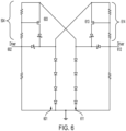
- Fig. 6 illustrates an example serving for a better understanding of the invention, but not belonging to the invention in which the sensors 604, 614 are voltage sensors.
- the detection of at least a threshold difference in voltage between the two sensors may trigger the switch to close.
- each of the FETs 603 and 613 will be a normally open switch.
- the first FET 603 is normally open, If the voltage across the voltage sensor 604 of the first section (in this case, biasing resistors) is more than a threshold amount more than the voltage across the second section's voltage sensor 614 (biasing resistors), the first section's FET 603 will turn on to create a conductive path between the first LED driver 602 and the second LED string 612 so that power from the first LED driver 602 is directed not only to the first LED string 601 but also to the second LED string 611.
- the second section's normally open switch (such as FET 613) will turn on and create a conductive path between the second LED driver 612 and the first LED string 601 so that power from the second LED driver 612 is directed not only to the second LED string 611 but also to the first LED string 601.
- the variation of Fig. 6 may be combined with those of Fig. 4 or Figs. 5A-5B by, for example, providing a parallel redundant driver with switch for either of the LED drivers 602, 612.
- the embodiments described above may be installed and included in the circuitry of an individual luminaire.
- some of the components, such as the buck driver and/or controller may be part of a control system that is external to the luminaire.
- Examples of luminaires and control systems that the embodiments disclosed above may be used in include, for example, those described in U.S. patent number 9,188,307 , titled "High Intensity LED Illumination Device with Automated Sensor-Based Control"; U.S. patent number 9,730,302 , titled “System and Method for Control of Illumination Device”; and U.S. patent number 9,800,431 , titled "Controllers for Interconnected Lighting Devices".
Landscapes
- Circuit Arrangement For Electric Light Sources In General (AREA)
Applications Claiming Priority (2)
| Application Number | Priority Date | Filing Date | Title |
|---|---|---|---|
| US16/414,963 US10841998B1 (en) | 2019-05-17 | 2019-05-17 | Shared power topology for LED luminaires |
| PCT/EP2020/063697 WO2020234183A1 (en) | 2019-05-17 | 2020-05-15 | Shared power topology for led luminaires |
Publications (2)
| Publication Number | Publication Date |
|---|---|
| EP3970453A1 EP3970453A1 (en) | 2022-03-23 |
| EP3970453B1 true EP3970453B1 (en) | 2024-06-26 |
Family
ID=70738581
Family Applications (1)
| Application Number | Title | Priority Date | Filing Date |
|---|---|---|---|
| EP20726122.3A Active EP3970453B1 (en) | 2019-05-17 | 2020-05-15 | Shared power topology for led luminaires |
Country Status (5)
| Country | Link |
|---|---|
| US (2) | US10841998B1 (cg-RX-API-DMAC7.html) |
| EP (1) | EP3970453B1 (cg-RX-API-DMAC7.html) |
| JP (1) | JP7503078B2 (cg-RX-API-DMAC7.html) |
| CN (1) | CN113841466B (cg-RX-API-DMAC7.html) |
| WO (1) | WO2020234183A1 (cg-RX-API-DMAC7.html) |
Families Citing this family (5)
| Publication number | Priority date | Publication date | Assignee | Title |
|---|---|---|---|---|
| US10841998B1 (en) * | 2019-05-17 | 2020-11-17 | Signify Holding B.V. | Shared power topology for LED luminaires |
| WO2023012113A1 (en) | 2021-08-03 | 2023-02-09 | Signify Holding B.V. | Redundant lighting driver system |
| CN114596821B (zh) * | 2022-05-09 | 2022-08-16 | 惠科股份有限公司 | 控制电路、控制方法和显示装置 |
| US12108503B2 (en) | 2022-12-20 | 2024-10-01 | Electronic Theatre Controls, Inc. | Independent lighting control |
| US12538406B2 (en) | 2022-12-20 | 2026-01-27 | Electronic Theatre Controls, Inc. | Independent lighting control |
Family Cites Families (53)
| Publication number | Priority date | Publication date | Assignee | Title |
|---|---|---|---|---|
| WO2011143510A1 (en) * | 2010-05-12 | 2011-11-17 | Lynk Labs, Inc. | Led lighting system |
| JP2005310571A (ja) * | 2004-04-22 | 2005-11-04 | Nec Saitama Ltd | カメラ機能付き携帯型電子機器 |
| US7075252B1 (en) | 2005-04-12 | 2006-07-11 | Eaton Corporation | LED driver circuit |
| JP2009545115A (ja) * | 2006-07-26 | 2009-12-17 | コーニンクレッカ フィリップス エレクトロニクス エヌ ヴィ | 機能不全時に電気素子を非活性化する装置及び方法 |
| US7520072B2 (en) | 2007-05-09 | 2009-04-21 | William Yu | Exit signs with and without emergency lighting |
| US20080295371A1 (en) * | 2007-05-30 | 2008-12-04 | Georgiana Hsu | Exit sign illuminated by color LEDs |
| WO2009064682A2 (en) * | 2007-11-16 | 2009-05-22 | Allegro Microsystems, Inc. | Electronic circuits for driving series connected light emitting diode strings |
| US9226343B2 (en) | 2007-11-30 | 2015-12-29 | Nuwave, Llc | Apparatus, system, method and computer program product for precise multistage programmable induction cooktop |
| CN201282580Y (zh) * | 2008-09-28 | 2009-07-29 | 张荣民 | 大功率led驱动电路 |
| JP4985669B2 (ja) | 2009-02-05 | 2012-07-25 | 株式会社デンソー | 発光ダイオード駆動回路 |
| KR100922336B1 (ko) * | 2009-02-17 | 2009-10-21 | 서철식 | Led 조명 장치 |
| US8564155B2 (en) * | 2009-05-06 | 2013-10-22 | Polar Semiconductor, Inc. | Multiple output power supply |
| CN102032521B (zh) | 2009-09-24 | 2013-08-07 | 富准精密工业(深圳)有限公司 | 发光二极管灯具 |
| CN101674693B (zh) | 2009-10-01 | 2012-07-18 | 英飞特电子(杭州)有限公司 | 一种适用于led驱动器的多路恒流控制电路 |
| CN102606966A (zh) * | 2011-01-25 | 2012-07-25 | 西安翌阳新能源技术工程有限公司 | 一种led发光装置 |
| FR2974671B1 (fr) * | 2011-04-28 | 2013-04-12 | Saint Gobain | Module a diodes électroluminescentes et vitrage lumineux avec un tel module a diodes |
| JP6532677B2 (ja) * | 2011-05-19 | 2019-06-19 | シグニファイ ホールディング ビー ヴィ | 光発生装置 |
| US20120306387A1 (en) | 2011-05-31 | 2012-12-06 | Microsemi Corporation | Led driver arrangement with multiple current mirrors |
| US9875697B2 (en) | 2011-08-30 | 2018-01-23 | Magnachip Semiconductor, Ltd. | Parallel constant current LED driving units for driving a LED string and method of performing the same |
| SG189603A1 (en) * | 2011-11-04 | 2013-05-31 | Opulent Electronics Internat Pte Ltd | System for driving a plurality of high powered led units |
| US9660535B2 (en) | 2011-11-11 | 2017-05-23 | Microchip Technology Incorporated | Method and system to dynamically position a switch mode power supply output voltage |
| TWI439170B (zh) * | 2012-04-12 | 2014-05-21 | Richtek Technology Corp | 可改善led裝置的使用率的驅動電路及相關的定電流調節器 |
| CN202647362U (zh) * | 2012-04-20 | 2013-01-02 | 甄钊伟 | 一种彩色led灯饰 |
| JP2013225449A (ja) * | 2012-04-23 | 2013-10-31 | Sharp Corp | 照明装置 |
| CN102802328B (zh) * | 2012-09-05 | 2015-09-09 | 英飞特电子(杭州)股份有限公司 | 一种led光源的恒流驱动器及led灯具 |
| ITPD20120410A1 (it) * | 2012-12-27 | 2014-06-28 | Automotive Lighting Italia Spa | Circuito di pilotaggio di sorgenti luminose e fanale automobilistico provvisto di detto circuito di pilotaggio di sorgenti luminose |
| CN104075166B (zh) * | 2013-03-26 | 2016-08-24 | 钰瀚科技股份有限公司 | 驱动数种颜色的发光二极管串的装置 |
| CN103247279B (zh) | 2013-05-13 | 2015-07-01 | 深圳市华星光电技术有限公司 | 一种发光半导体光源驱动电路及背光模组 |
| RU2673249C2 (ru) | 2013-11-25 | 2018-11-23 | Филипс Лайтинг Холдинг Б.В. | Способ управления устройством освещения, средство управления освещением и система освещения |
| CN104717784B (zh) * | 2013-12-13 | 2018-09-14 | 台达电子企业管理(上海)有限公司 | 光源驱动电路 |
| CA2875014A1 (en) | 2013-12-17 | 2015-06-17 | Ephesus Lighting, Inc. | Lens structure for high intensity led fixture |
| JP6238166B2 (ja) * | 2013-12-20 | 2017-11-29 | パナソニックIpマネジメント株式会社 | 発光ユニット及び照明装置 |
| KR20160017816A (ko) | 2014-08-06 | 2016-02-17 | 삼성디스플레이 주식회사 | 광원 장치, 이의 구동 방법 및 이를 갖는 표시 장치 |
| JP6332629B2 (ja) * | 2014-09-11 | 2018-05-30 | 岩崎電気株式会社 | Led電源及びled照明装置 |
| DE102015104973B3 (de) * | 2015-03-31 | 2016-08-18 | Varroc Lighting Systems, s.r.o. | Anordnung und Verfahren zur Ansteuerung von mehreren in einer Reihenschaltung angeordneten Leuchtdioden |
| CN107683630B (zh) | 2015-04-23 | 2020-11-10 | 港大科桥有限公司 | Ac-dc单个电感器多个输出led驱动器 |
| CN104869711A (zh) * | 2015-05-15 | 2015-08-26 | 西交利物浦大学 | 一种谐振型大功率多路输出led驱动电源 |
| CN105323923B (zh) | 2015-10-27 | 2018-11-30 | 浙江生辉照明有限公司 | Led智能控制电路及led照明装置 |
| CN106922069B (zh) * | 2015-12-25 | 2023-05-16 | 四川新力光源股份有限公司 | 一种防电源故障灯箱 |
| WO2017117195A1 (en) | 2015-12-28 | 2017-07-06 | Ephesus Lighting, Inc. | System and method for control of an illumination device |
| CN109076681B (zh) | 2016-03-08 | 2020-04-17 | 伊顿智能动力有限公司 | 用于互连照明装置的控制器 |
| JP6757579B2 (ja) * | 2016-03-18 | 2020-09-23 | ローム株式会社 | 発光素子駆動装置、発光装置、車両 |
| EP3443813A4 (en) * | 2016-04-11 | 2019-11-20 | Eaton Intelligent Power Limited | Fail-safe led system |
| WO2018069464A1 (de) * | 2016-10-13 | 2018-04-19 | Elmos Semiconductor Aktiengesellschaft | Led-beleuchtungsvorrichtung, insbesondere für fahrzeuge |
| US9717123B1 (en) | 2016-10-17 | 2017-07-25 | Integrated Silicon Solution, Inc. | Audible noise reduction method for multiple LED channel systems |
| US9924574B1 (en) | 2016-10-28 | 2018-03-20 | Uledo Llc. | Method and apparatus for controlling light output from a LED lamp |
| WO2018166856A1 (en) * | 2017-03-14 | 2018-09-20 | Lumileds Holding B.V. | Led lighting circuit |
| CN108811221B (zh) * | 2017-04-26 | 2020-08-04 | 嘉兴海拉灯具有限公司 | 一种led驱动装置、驱动方法及led灯具 |
| US10334676B2 (en) | 2017-05-17 | 2019-06-25 | Eaton Intelligent Power Limited | LED luminaire with constant current per-module control |
| US11812525B2 (en) * | 2017-06-27 | 2023-11-07 | Wangs Alliance Corporation | Methods and apparatus for controlling the current supplied to light emitting diodes |
| US10455672B2 (en) | 2017-08-23 | 2019-10-22 | Eaton Intelligent Power Limited | Time-based lighting control |
| US10841998B1 (en) * | 2019-05-17 | 2020-11-17 | Signify Holding B.V. | Shared power topology for LED luminaires |
| US11985175B2 (en) | 2020-03-25 | 2024-05-14 | Snap Inc. | Virtual interaction session to facilitate time limited augmented reality based communication between multiple users |
-
2019
- 2019-05-17 US US16/414,963 patent/US10841998B1/en active Active
-
2020
- 2020-05-15 CN CN202080036485.3A patent/CN113841466B/zh active Active
- 2020-05-15 JP JP2021568617A patent/JP7503078B2/ja active Active
- 2020-05-15 WO PCT/EP2020/063697 patent/WO2020234183A1/en not_active Ceased
- 2020-05-15 EP EP20726122.3A patent/EP3970453B1/en active Active
- 2020-05-15 US US17/609,688 patent/US11930572B2/en active Active
Also Published As
| Publication number | Publication date |
|---|---|
| JP2022533175A (ja) | 2022-07-21 |
| WO2020234183A1 (en) | 2020-11-26 |
| US10841998B1 (en) | 2020-11-17 |
| JP7503078B2 (ja) | 2024-06-19 |
| CN113841466B (zh) | 2024-07-23 |
| US11930572B2 (en) | 2024-03-12 |
| US20220225484A1 (en) | 2022-07-14 |
| CN113841466A (zh) | 2021-12-24 |
| US20200367330A1 (en) | 2020-11-19 |
| EP3970453A1 (en) | 2022-03-23 |
Similar Documents
| Publication | Publication Date | Title |
|---|---|---|
| EP3970453B1 (en) | Shared power topology for led luminaires | |
| US10327290B2 (en) | Lighting circuit and vehicle lamp | |
| US10797516B2 (en) | Lighting system including a power backup device | |
| EP2073605A1 (en) | Lighting controller of lighting device for vehicle | |
| US8294371B2 (en) | LED traffic signal with synchronized power pulse circuit | |
| US20120194075A1 (en) | Lighting device and luminaire | |
| US9096173B2 (en) | Control circuit for a dual-function signaling or lighting device and corresponding control method | |
| EP2826341A1 (en) | Shunt device in lighting control system without neutral wire | |
| CN204119603U (zh) | 点灯装置以及照明装置 | |
| EP2838318A1 (en) | Lighting circuit and luminiare | |
| JP2014191933A (ja) | 標識灯装置 | |
| US20150189712A1 (en) | Led lighting arrangement and method of controlling a led lighting arrangement | |
| US20180054863A1 (en) | Solid State Lighting Driver Circuit with Ballast Compatibility | |
| US20210100079A1 (en) | Led luminaire multiplexing with constant current driver | |
| US20210345463A1 (en) | System and method for repurposing 120vac wiring architecture to retrofitable low voltage dc power 2-wire led dimming | |
| KR101753193B1 (ko) | 병렬 연결된 led모듈의 pwm제어를 통한 led등기구의 전류 컨트롤방법 | |
| US20140145645A1 (en) | Step-dimming led driver and system | |
| US9307610B2 (en) | Low power bypass circuit for LED open circuit and reverse polarity protection | |
| EP3089556A1 (en) | Illumination lamp, illumination apparatus, and illumination control circuit | |
| US10009973B1 (en) | Redundant power for lighting system | |
| KR102608623B1 (ko) | 스포츠 조명 시스템 | |
| FI20245092A1 (en) | Led driver apparatus and led lighting arrangement | |
| KR20140090748A (ko) | Led램프용 보호회로 |
Legal Events
| Date | Code | Title | Description |
|---|---|---|---|
| STAA | Information on the status of an ep patent application or granted ep patent |
Free format text: STATUS: UNKNOWN |
|
| STAA | Information on the status of an ep patent application or granted ep patent |
Free format text: STATUS: THE INTERNATIONAL PUBLICATION HAS BEEN MADE |
|
| PUAI | Public reference made under article 153(3) epc to a published international application that has entered the european phase |
Free format text: ORIGINAL CODE: 0009012 |
|
| STAA | Information on the status of an ep patent application or granted ep patent |
Free format text: STATUS: REQUEST FOR EXAMINATION WAS MADE |
|
| 17P | Request for examination filed |
Effective date: 20211217 |
|
| AK | Designated contracting states |
Kind code of ref document: A1 Designated state(s): AL AT BE BG CH CY CZ DE DK EE ES FI FR GB GR HR HU IE IS IT LI LT LU LV MC MK MT NL NO PL PT RO RS SE SI SK SM TR |
|
| DAV | Request for validation of the european patent (deleted) | ||
| DAX | Request for extension of the european patent (deleted) | ||
| STAA | Information on the status of an ep patent application or granted ep patent |
Free format text: STATUS: EXAMINATION IS IN PROGRESS |
|
| 17Q | First examination report despatched |
Effective date: 20230502 |
|
| GRAP | Despatch of communication of intention to grant a patent |
Free format text: ORIGINAL CODE: EPIDOSNIGR1 |
|
| STAA | Information on the status of an ep patent application or granted ep patent |
Free format text: STATUS: GRANT OF PATENT IS INTENDED |
|
| INTG | Intention to grant announced |
Effective date: 20240131 |
|
| GRAS | Grant fee paid |
Free format text: ORIGINAL CODE: EPIDOSNIGR3 |
|
| GRAA | (expected) grant |
Free format text: ORIGINAL CODE: 0009210 |
|
| STAA | Information on the status of an ep patent application or granted ep patent |
Free format text: STATUS: THE PATENT HAS BEEN GRANTED |
|
| P01 | Opt-out of the competence of the unified patent court (upc) registered |
Effective date: 20240419 |
|
| AK | Designated contracting states |
Kind code of ref document: B1 Designated state(s): AL AT BE BG CH CY CZ DE DK EE ES FI FR GB GR HR HU IE IS IT LI LT LU LV MC MK MT NL NO PL PT RO RS SE SI SK SM TR |
|
| REG | Reference to a national code |
Ref country code: GB Ref legal event code: FG4D |
|
| REG | Reference to a national code |
Ref country code: CH Ref legal event code: EP |
|
| REG | Reference to a national code |
Ref country code: DE Ref legal event code: R096 Ref document number: 602020032964 Country of ref document: DE |
|
| PG25 | Lapsed in a contracting state [announced via postgrant information from national office to epo] |
Ref country code: BG Free format text: LAPSE BECAUSE OF FAILURE TO SUBMIT A TRANSLATION OF THE DESCRIPTION OR TO PAY THE FEE WITHIN THE PRESCRIBED TIME-LIMIT Effective date: 20240626 |
|
| PG25 | Lapsed in a contracting state [announced via postgrant information from national office to epo] |
Ref country code: FI Free format text: LAPSE BECAUSE OF FAILURE TO SUBMIT A TRANSLATION OF THE DESCRIPTION OR TO PAY THE FEE WITHIN THE PRESCRIBED TIME-LIMIT Effective date: 20240626 Ref country code: HR Free format text: LAPSE BECAUSE OF FAILURE TO SUBMIT A TRANSLATION OF THE DESCRIPTION OR TO PAY THE FEE WITHIN THE PRESCRIBED TIME-LIMIT Effective date: 20240626 |
|
| REG | Reference to a national code |
Ref country code: LT Ref legal event code: MG9D |
|
| PG25 | Lapsed in a contracting state [announced via postgrant information from national office to epo] |
Ref country code: GR Free format text: LAPSE BECAUSE OF FAILURE TO SUBMIT A TRANSLATION OF THE DESCRIPTION OR TO PAY THE FEE WITHIN THE PRESCRIBED TIME-LIMIT Effective date: 20240927 |
|
| PG25 | Lapsed in a contracting state [announced via postgrant information from national office to epo] |
Ref country code: LV Free format text: LAPSE BECAUSE OF FAILURE TO SUBMIT A TRANSLATION OF THE DESCRIPTION OR TO PAY THE FEE WITHIN THE PRESCRIBED TIME-LIMIT Effective date: 20240626 |
|
| REG | Reference to a national code |
Ref country code: NL Ref legal event code: MP Effective date: 20240626 |
|
| PG25 | Lapsed in a contracting state [announced via postgrant information from national office to epo] |
Ref country code: NO Free format text: LAPSE BECAUSE OF FAILURE TO SUBMIT A TRANSLATION OF THE DESCRIPTION OR TO PAY THE FEE WITHIN THE PRESCRIBED TIME-LIMIT Effective date: 20240926 Ref country code: LV Free format text: LAPSE BECAUSE OF FAILURE TO SUBMIT A TRANSLATION OF THE DESCRIPTION OR TO PAY THE FEE WITHIN THE PRESCRIBED TIME-LIMIT Effective date: 20240626 Ref country code: HR Free format text: LAPSE BECAUSE OF FAILURE TO SUBMIT A TRANSLATION OF THE DESCRIPTION OR TO PAY THE FEE WITHIN THE PRESCRIBED TIME-LIMIT Effective date: 20240626 Ref country code: GR Free format text: LAPSE BECAUSE OF FAILURE TO SUBMIT A TRANSLATION OF THE DESCRIPTION OR TO PAY THE FEE WITHIN THE PRESCRIBED TIME-LIMIT Effective date: 20240927 Ref country code: FI Free format text: LAPSE BECAUSE OF FAILURE TO SUBMIT A TRANSLATION OF THE DESCRIPTION OR TO PAY THE FEE WITHIN THE PRESCRIBED TIME-LIMIT Effective date: 20240626 Ref country code: BG Free format text: LAPSE BECAUSE OF FAILURE TO SUBMIT A TRANSLATION OF THE DESCRIPTION OR TO PAY THE FEE WITHIN THE PRESCRIBED TIME-LIMIT Effective date: 20240626 Ref country code: RS Free format text: LAPSE BECAUSE OF FAILURE TO SUBMIT A TRANSLATION OF THE DESCRIPTION OR TO PAY THE FEE WITHIN THE PRESCRIBED TIME-LIMIT Effective date: 20240926 |
|
| PG25 | Lapsed in a contracting state [announced via postgrant information from national office to epo] |
Ref country code: NL Free format text: LAPSE BECAUSE OF FAILURE TO SUBMIT A TRANSLATION OF THE DESCRIPTION OR TO PAY THE FEE WITHIN THE PRESCRIBED TIME-LIMIT Effective date: 20240626 |
|
| REG | Reference to a national code |
Ref country code: AT Ref legal event code: MK05 Ref document number: 1698765 Country of ref document: AT Kind code of ref document: T Effective date: 20240626 |
|
| PG25 | Lapsed in a contracting state [announced via postgrant information from national office to epo] |
Ref country code: NL Free format text: LAPSE BECAUSE OF FAILURE TO SUBMIT A TRANSLATION OF THE DESCRIPTION OR TO PAY THE FEE WITHIN THE PRESCRIBED TIME-LIMIT Effective date: 20240626 |
|
| PG25 | Lapsed in a contracting state [announced via postgrant information from national office to epo] |
Ref country code: PT Free format text: LAPSE BECAUSE OF FAILURE TO SUBMIT A TRANSLATION OF THE DESCRIPTION OR TO PAY THE FEE WITHIN THE PRESCRIBED TIME-LIMIT Effective date: 20241028 |
|
| PG25 | Lapsed in a contracting state [announced via postgrant information from national office to epo] |
Ref country code: PT Free format text: LAPSE BECAUSE OF FAILURE TO SUBMIT A TRANSLATION OF THE DESCRIPTION OR TO PAY THE FEE WITHIN THE PRESCRIBED TIME-LIMIT Effective date: 20241028 |
|
| PG25 | Lapsed in a contracting state [announced via postgrant information from national office to epo] |
Ref country code: PL Free format text: LAPSE BECAUSE OF FAILURE TO SUBMIT A TRANSLATION OF THE DESCRIPTION OR TO PAY THE FEE WITHIN THE PRESCRIBED TIME-LIMIT Effective date: 20240626 |
|
| PG25 | Lapsed in a contracting state [announced via postgrant information from national office to epo] |
Ref country code: EE Free format text: LAPSE BECAUSE OF FAILURE TO SUBMIT A TRANSLATION OF THE DESCRIPTION OR TO PAY THE FEE WITHIN THE PRESCRIBED TIME-LIMIT Effective date: 20240626 |
|
| PG25 | Lapsed in a contracting state [announced via postgrant information from national office to epo] |
Ref country code: AT Free format text: LAPSE BECAUSE OF FAILURE TO SUBMIT A TRANSLATION OF THE DESCRIPTION OR TO PAY THE FEE WITHIN THE PRESCRIBED TIME-LIMIT Effective date: 20240626 Ref country code: IS Free format text: LAPSE BECAUSE OF FAILURE TO SUBMIT A TRANSLATION OF THE DESCRIPTION OR TO PAY THE FEE WITHIN THE PRESCRIBED TIME-LIMIT Effective date: 20241026 |
|
| PG25 | Lapsed in a contracting state [announced via postgrant information from national office to epo] |
Ref country code: CZ Free format text: LAPSE BECAUSE OF FAILURE TO SUBMIT A TRANSLATION OF THE DESCRIPTION OR TO PAY THE FEE WITHIN THE PRESCRIBED TIME-LIMIT Effective date: 20240626 |
|
| PG25 | Lapsed in a contracting state [announced via postgrant information from national office to epo] |
Ref country code: SK Free format text: LAPSE BECAUSE OF FAILURE TO SUBMIT A TRANSLATION OF THE DESCRIPTION OR TO PAY THE FEE WITHIN THE PRESCRIBED TIME-LIMIT Effective date: 20240626 Ref country code: RO Free format text: LAPSE BECAUSE OF FAILURE TO SUBMIT A TRANSLATION OF THE DESCRIPTION OR TO PAY THE FEE WITHIN THE PRESCRIBED TIME-LIMIT Effective date: 20240626 |
|
| PG25 | Lapsed in a contracting state [announced via postgrant information from national office to epo] |
Ref country code: ES Free format text: LAPSE BECAUSE OF FAILURE TO SUBMIT A TRANSLATION OF THE DESCRIPTION OR TO PAY THE FEE WITHIN THE PRESCRIBED TIME-LIMIT Effective date: 20240626 Ref country code: SM Free format text: LAPSE BECAUSE OF FAILURE TO SUBMIT A TRANSLATION OF THE DESCRIPTION OR TO PAY THE FEE WITHIN THE PRESCRIBED TIME-LIMIT Effective date: 20240626 |
|
| PG25 | Lapsed in a contracting state [announced via postgrant information from national office to epo] |
Ref country code: SM Free format text: LAPSE BECAUSE OF FAILURE TO SUBMIT A TRANSLATION OF THE DESCRIPTION OR TO PAY THE FEE WITHIN THE PRESCRIBED TIME-LIMIT Effective date: 20240626 Ref country code: SK Free format text: LAPSE BECAUSE OF FAILURE TO SUBMIT A TRANSLATION OF THE DESCRIPTION OR TO PAY THE FEE WITHIN THE PRESCRIBED TIME-LIMIT Effective date: 20240626 Ref country code: RO Free format text: LAPSE BECAUSE OF FAILURE TO SUBMIT A TRANSLATION OF THE DESCRIPTION OR TO PAY THE FEE WITHIN THE PRESCRIBED TIME-LIMIT Effective date: 20240626 Ref country code: PL Free format text: LAPSE BECAUSE OF FAILURE TO SUBMIT A TRANSLATION OF THE DESCRIPTION OR TO PAY THE FEE WITHIN THE PRESCRIBED TIME-LIMIT Effective date: 20240626 Ref country code: IS Free format text: LAPSE BECAUSE OF FAILURE TO SUBMIT A TRANSLATION OF THE DESCRIPTION OR TO PAY THE FEE WITHIN THE PRESCRIBED TIME-LIMIT Effective date: 20241026 Ref country code: ES Free format text: LAPSE BECAUSE OF FAILURE TO SUBMIT A TRANSLATION OF THE DESCRIPTION OR TO PAY THE FEE WITHIN THE PRESCRIBED TIME-LIMIT Effective date: 20240626 Ref country code: EE Free format text: LAPSE BECAUSE OF FAILURE TO SUBMIT A TRANSLATION OF THE DESCRIPTION OR TO PAY THE FEE WITHIN THE PRESCRIBED TIME-LIMIT Effective date: 20240626 Ref country code: CZ Free format text: LAPSE BECAUSE OF FAILURE TO SUBMIT A TRANSLATION OF THE DESCRIPTION OR TO PAY THE FEE WITHIN THE PRESCRIBED TIME-LIMIT Effective date: 20240626 Ref country code: AT Free format text: LAPSE BECAUSE OF FAILURE TO SUBMIT A TRANSLATION OF THE DESCRIPTION OR TO PAY THE FEE WITHIN THE PRESCRIBED TIME-LIMIT Effective date: 20240626 |
|
| PG25 | Lapsed in a contracting state [announced via postgrant information from national office to epo] |
Ref country code: IT Free format text: LAPSE BECAUSE OF FAILURE TO SUBMIT A TRANSLATION OF THE DESCRIPTION OR TO PAY THE FEE WITHIN THE PRESCRIBED TIME-LIMIT Effective date: 20240626 |
|
| REG | Reference to a national code |
Ref country code: DE Ref legal event code: R097 Ref document number: 602020032964 Country of ref document: DE |
|
| PG25 | Lapsed in a contracting state [announced via postgrant information from national office to epo] |
Ref country code: DK Free format text: LAPSE BECAUSE OF FAILURE TO SUBMIT A TRANSLATION OF THE DESCRIPTION OR TO PAY THE FEE WITHIN THE PRESCRIBED TIME-LIMIT Effective date: 20240626 |
|
| PLBE | No opposition filed within time limit |
Free format text: ORIGINAL CODE: 0009261 |
|
| STAA | Information on the status of an ep patent application or granted ep patent |
Free format text: STATUS: NO OPPOSITION FILED WITHIN TIME LIMIT |
|
| 26N | No opposition filed |
Effective date: 20250327 |
|
| PGFP | Annual fee paid to national office [announced via postgrant information from national office to epo] |
Ref country code: FR Payment date: 20250526 Year of fee payment: 6 |
|
| PG25 | Lapsed in a contracting state [announced via postgrant information from national office to epo] |
Ref country code: SE Free format text: LAPSE BECAUSE OF FAILURE TO SUBMIT A TRANSLATION OF THE DESCRIPTION OR TO PAY THE FEE WITHIN THE PRESCRIBED TIME-LIMIT Effective date: 20240626 |
|
| PGFP | Annual fee paid to national office [announced via postgrant information from national office to epo] |
Ref country code: DE Payment date: 20250728 Year of fee payment: 6 |
|
| REG | Reference to a national code |
Ref country code: CH Ref legal event code: H13 Free format text: ST27 STATUS EVENT CODE: U-0-0-H10-H13 (AS PROVIDED BY THE NATIONAL OFFICE) Effective date: 20251223 |
|
| PG25 | Lapsed in a contracting state [announced via postgrant information from national office to epo] |
Ref country code: LU Free format text: LAPSE BECAUSE OF NON-PAYMENT OF DUE FEES Effective date: 20250515 |
|
| PG25 | Lapsed in a contracting state [announced via postgrant information from national office to epo] |
Ref country code: CH Free format text: LAPSE BECAUSE OF NON-PAYMENT OF DUE FEES Effective date: 20250531 |
|
| REG | Reference to a national code |
Ref country code: BE Ref legal event code: MM Effective date: 20250531 |
|
| PG25 | Lapsed in a contracting state [announced via postgrant information from national office to epo] |
Ref country code: MC Free format text: LAPSE BECAUSE OF FAILURE TO SUBMIT A TRANSLATION OF THE DESCRIPTION OR TO PAY THE FEE WITHIN THE PRESCRIBED TIME-LIMIT Effective date: 20240626 |
|
| PGFP | Annual fee paid to national office [announced via postgrant information from national office to epo] |
Ref country code: GB Payment date: 20260304 Year of fee payment: 7 |
|
| PG25 | Lapsed in a contracting state [announced via postgrant information from national office to epo] |
Ref country code: IE Free format text: LAPSE BECAUSE OF NON-PAYMENT OF DUE FEES Effective date: 20250515 |
|
| PG25 | Lapsed in a contracting state [announced via postgrant information from national office to epo] |
Ref country code: BE Free format text: LAPSE BECAUSE OF NON-PAYMENT OF DUE FEES Effective date: 20250531 |