EP3969194B1 - Warmwalzen mit flexibler konfiguration der walzgerüste - Google Patents
Warmwalzen mit flexibler konfiguration der walzgerüste Download PDFInfo
- Publication number
- EP3969194B1 EP3969194B1 EP20725630.6A EP20725630A EP3969194B1 EP 3969194 B1 EP3969194 B1 EP 3969194B1 EP 20725630 A EP20725630 A EP 20725630A EP 3969194 B1 EP3969194 B1 EP 3969194B1
- Authority
- EP
- European Patent Office
- Prior art keywords
- stand
- rolling
- rolls
- metal strip
- last
- Prior art date
- Legal status (The legal status is an assumption and is not a legal conclusion. Google has not performed a legal analysis and makes no representation as to the accuracy of the status listed.)
- Active
Links
Images


Classifications
-
- B—PERFORMING OPERATIONS; TRANSPORTING
- B21—MECHANICAL METAL-WORKING WITHOUT ESSENTIALLY REMOVING MATERIAL; PUNCHING METAL
- B21B—ROLLING OF METAL
- B21B13/00—Metal-rolling stands, i.e. an assembly composed of a stand frame, rolls, and accessories
- B21B13/001—Convertible or tiltable stands, e.g. from duo to universal stands, from horizontal to vertical stands
-
- B—PERFORMING OPERATIONS; TRANSPORTING
- B21—MECHANICAL METAL-WORKING WITHOUT ESSENTIALLY REMOVING MATERIAL; PUNCHING METAL
- B21B—ROLLING OF METAL
- B21B31/00—Rolling stand structures; Mounting, adjusting, or interchanging rolls, roll mountings, or stand frames
- B21B31/08—Interchanging rolls, roll mountings, or stand frames, e.g. using C-hooks; Replacing roll chocks on roll shafts
-
- B—PERFORMING OPERATIONS; TRANSPORTING
- B21—MECHANICAL METAL-WORKING WITHOUT ESSENTIALLY REMOVING MATERIAL; PUNCHING METAL
- B21B—ROLLING OF METAL
- B21B1/00—Metal-rolling methods or mills for making semi-finished products of solid or profiled cross-section; Sequence of operations in milling trains; Layout of rolling-mill plant, e.g. grouping of stands; Succession of passes or of sectional pass alternations
- B21B1/46—Metal-rolling methods or mills for making semi-finished products of solid or profiled cross-section; Sequence of operations in milling trains; Layout of rolling-mill plant, e.g. grouping of stands; Succession of passes or of sectional pass alternations for rolling metal immediately subsequent to continuous casting
-
- B—PERFORMING OPERATIONS; TRANSPORTING
- B21—MECHANICAL METAL-WORKING WITHOUT ESSENTIALLY REMOVING MATERIAL; PUNCHING METAL
- B21B—ROLLING OF METAL
- B21B1/00—Metal-rolling methods or mills for making semi-finished products of solid or profiled cross-section; Sequence of operations in milling trains; Layout of rolling-mill plant, e.g. grouping of stands; Succession of passes or of sectional pass alternations
- B21B1/22—Metal-rolling methods or mills for making semi-finished products of solid or profiled cross-section; Sequence of operations in milling trains; Layout of rolling-mill plant, e.g. grouping of stands; Succession of passes or of sectional pass alternations for rolling plates, strips, bands or sheets of indefinite length
- B21B2001/225—Metal-rolling methods or mills for making semi-finished products of solid or profiled cross-section; Sequence of operations in milling trains; Layout of rolling-mill plant, e.g. grouping of stands; Succession of passes or of sectional pass alternations for rolling plates, strips, bands or sheets of indefinite length by hot-rolling
-
- B—PERFORMING OPERATIONS; TRANSPORTING
- B21—MECHANICAL METAL-WORKING WITHOUT ESSENTIALLY REMOVING MATERIAL; PUNCHING METAL
- B21B—ROLLING OF METAL
- B21B13/00—Metal-rolling stands, i.e. an assembly composed of a stand frame, rolls, and accessories
- B21B13/02—Metal-rolling stands, i.e. an assembly composed of a stand frame, rolls, and accessories with axes of rolls arranged horizontally
- B21B2013/025—Quarto, four-high stands
-
- B—PERFORMING OPERATIONS; TRANSPORTING
- B21—MECHANICAL METAL-WORKING WITHOUT ESSENTIALLY REMOVING MATERIAL; PUNCHING METAL
- B21B—ROLLING OF METAL
- B21B13/00—Metal-rolling stands, i.e. an assembly composed of a stand frame, rolls, and accessories
- B21B13/02—Metal-rolling stands, i.e. an assembly composed of a stand frame, rolls, and accessories with axes of rolls arranged horizontally
- B21B2013/028—Sixto, six-high stands
-
- B—PERFORMING OPERATIONS; TRANSPORTING
- B21—MECHANICAL METAL-WORKING WITHOUT ESSENTIALLY REMOVING MATERIAL; PUNCHING METAL
- B21B—ROLLING OF METAL
- B21B2267/00—Roll parameters
- B21B2267/02—Roll dimensions
- B21B2267/06—Roll diameter
Definitions
- finishing lines for rolling metal strips are usually operated in this way and finishing lines for rolling metal strips (particularly made of steel) are usually designed in this way.
- the last rolling stand (and usually also the other rolling stands of the finishing line) is converted in order to replace worn work rolls and, if necessary, worn backup rolls.
- the configuration of the The rolling stands are not changed. There is only a 1:1 exchange of roller pairs.
- the rolling stands of hot rolling mills are usually designed as so-called four-high stands.
- Four-high stands are rolling stands that have backup rolls in addition to the work rolls, on which the work rolls are supported. In English-speaking countries, such rolling stands are often also referred to as 4-high.
- the problem is usually solved by using work rolls with the smallest possible diameter.
- the smaller the diameter of the work rolls the lower the torque with which the work rolls can be driven without risking the roll neck breaking.
- the torque is higher with harder materials. This creates the problem that on the one hand the diameter of the work rolls should be as small as possible in order to achieve the smallest possible final thickness, but on the other hand it must not be too small, otherwise the required torque cannot be transmitted.
- rolling stands that have a large number of rolls, for example so-called 12-roll rolling stands or 20-roll rolling stands.
- Such rolling stands cannot be used in hot rolling because they take up too much space and do not allow sufficient cooling of the rolls - especially the work rolls.
- a rolling mill which has three sequentially successive rolling mills.
- the first rolling mill is a roughing mill and has four-high rolling mill stands.
- the second rolling mill is a finishing mill and also has four-high rolling mill stands.
- the third rolling mill is connected to the finishing mill, with temperature control devices arranged between the finishing mill and the third rolling mill.
- the third rolling mill has four-high rolling mill stands or six-high rolling mill stands.
- the preamble of claim 1 is based on this document.
- From the US 2 039 959 A is a rolling mill stand designed as a six-high stand that can be operated as a four-high stand after the work rolls have been removed. In this state, the intermediate rolls serve as work rolls.
- the object of the present invention is to create possibilities to produce materials with higher strength with low final thicknesses in a hot rolling mill.
- an operating method of the type mentioned at the outset is designed in that, as part of the conversion of the last rolling stand, the last rolling stand is converted from a four-high stand to a six-high stand or vice versa between the rolling of the first metal strip and the rolling of the second metal strip, so that the last rolling stand is configured as a four-high stand with work rolls and backup rolls during the rolling of the first metal strip and as a six-high stand with work rolls, intermediate rolls and backup rolls during the rolling of the second metal strip, and that the further rolling stands are configured as four-high stands both during the rolling of the first metal strip and during the rolling of the second metal strip.
- This conversion makes it possible to roll a metal strip made of a softer material or to roll a metal strip to a greater final thickness, while the last rolling stand - as in the prior art - is configured as a four-high stand. However, if a metal strip made of a harder material is to be rolled to a small final thickness, the last rolling stand can be converted to a six-high stand according to the invention.
- the rolling plan i.e. the sequence of metal strips to be rolled one after the other
- the last rolling stand is converted at a time when the work rolls currently in the last rolling stand would have to be removed anyway due to wear.
- This procedure leads to optimized productivity.
- the conversion can also be carried out regardless of the state of wear of the work rolls and thus regardless of a replacement of the work rolls (in a four-high stand) or the work rolls and possibly also the intermediate rolls (in a six-high stand) due to wear.
- the sum of the diameters of the work rolls and intermediate rolls of the last rolling stand configured as a six-high stand corresponds at least approximately - namely to within 20%, preferably to within 10% - to the diameter of the work rolls of the last rolling stand configured as a four-high stand. This allows the adjustment range of the last rolling stand to be optimally utilized both in the four-high stand configuration and in the six-high stand configuration.
- the conversion of the last rolling stand from a four-high stand to a six-high stand is preferably carried out by removing work rolls from the last rolling stand configured as a four-high stand and installing work rolls and intermediate rolls from the last rolling stand configured as a six-high stand.
- the conversion of the last rolling stand from a Converting a six-high stand into a four-high stand preferably by removing the work rolls and the intermediate rolls of the last rolling stand configured as a six-high stand and installing the work rolls of the last rolling stand configured as a four-high stand.
- the work rolls and the intermediate rolls of the last rolling stand configured as a six-high stand are preferably installed or removed as a unit. This allows the conversion to be carried out particularly quickly.
- the hot rolling mill has a number of additional rolling stands between the first and the last rolling stand, for example two additional rolling stands, three additional rolling stands or four additional rolling stands, so that - including the first rolling stand and the last rolling stand - there are a total of four, five or six rolling stands.
- the additional rolling stands are configured as four-high stands both during the rolling of the first metal strip and during the rolling of the second metal strip. This means that only the last rolling stand is converted.
- the work rolls of the last rolling stand configured as a six-high stand may be driven.
- these work rolls preferably have a diameter that is at least as large as the diameter of the intermediate rolls of the last rolling stand configured as a six-high stand.
- the intermediate rolls of the last rolling stand configured as a six-high stand it is possible for the intermediate rolls of the last rolling stand configured as a six-high stand to be driven.
- the work rolls of the last rolling stand configured as a six-high stand preferably have a diameter that is between 50% and 70% of the diameter of the intermediate rolls of the last rolling stand configured as a six-high stand.
- a hot rolling mill has several rolling stands 1a to 1d.
- the hot rolling mill can be designed in particular as a finishing mill.
- a first metal strip 2 is hot rolled in the hot rolling mill.
- the first metal strip 2 can in particular be a steel strip.
- the first metal strip 2 runs through the hot rolling mill without stopping and without reversing direction in a transport direction x.
- the individual sections of the first metal strip 2 thus first pass through the first rolling stand 1a, then the second rolling stand 1b, then the third rolling stand 1c and finally the last rolling stand 1d.
- the first metal strip 2 Before rolling in the first rolling stand 1a, the first metal strip 2 can be heated to the required rolling temperature, for example in a furnace (not shown).
- the rolling temperature for a steel strip is usually between 900 °C and 1200 °C.
- the first metal strip 2 can be wound up into a coil (not shown), for example.
- all rolling stands 1a to 1d of the hot rolling mill are configured as four-high stands.
- the rolling stands 1a to 1d each have work rolls 3 and backup rolls 4, but no further rolls. This also applies in particular to the first and last rolling stands 1a, 1d of the hot rolling mill.
- FIG 2 shows the same hot rolling mill with the same rolling stands 1a to 1d during the rolling of a second metal strip 5.
- the first rolling stand 1a is still configured as a four-high stand at this time, i.e. during the rolling of the second metal strip 5.
- at least the last rolling stand 1d is configured as a six-high stand.
- the backup rolls 4 it therefore has work rolls 6 and intermediate rolls 7.
- the intermediate rolls 7 are arranged between the backup rolls 4 and the work rolls 6.
- the other rolling stands 1b, 1c are as shown in FIG 2 are still configured as four-high stands even during the rolling of the second metal strip 5.
- the working rolls 3 are usually driven.
- the working rolls 6 are also usually driven.
- the intermediate rolls 7 can also be driven - usually alternatively.
- the last rolling stand 1d is converted from a four-high stand to a six-high stand between the rolling of the first metal strip 2 and the rolling of the second metal strip 5.
- the working rolls 3 of the four-high stand are dismantled.
- the dismantling is carried out as is generally customary and in FIG 3 indicated by an arrow A, in the axial direction of the working rolls 3 through the window of the operator-side stand. Dashed lines are in FIG 3 the removed work rolls 3 are also shown.
- the last rolling stand 1d is used as required either as a four-high stand - see in FIG 5 left - or as a sexto frame - see in FIG 5 right - configured.
- the backup rolls 4 are not changed when the last rolling stand 1d is converted.
- the backup rolls 4 are therefore the same in the configuration of the last rolling stand 1d as well as Both in the four-high stand and in the configuration of the last rolling stand 1d as a six-high stand, the same support rolls 4 are used.
- the working rolls 6 and the intermediate rolls 7 of the six-high stand are arranged in a cassette 8.
- the working rolls 6 and the intermediate rolls 7 of the six-high stand can also be installed as a unit, ie in particular simultaneously.
- the diameters D, D' and D" of the work rolls 3, the work rolls 6 and the intermediate rolls 7 should preferably be coordinated with one another in such a way that the sum of the diameters D', D" of the work rolls 6 and the intermediate rolls 7 of the six-high stand at least approximately corresponds to the diameter of the work rolls 3 of the four-high stand. Smaller deviations of a maximum of 20%, preferably a maximum of 10%, can, however, be tolerated.
- the diameters D', D" of the work rolls 6 and the intermediate rolls 7 in the configuration of the last rolling stand 1d as a six-high stand should also be determined taking into account whether the work rolls 6 or the intermediate rolls 7 are driven.
- the diameter D' of the work rolls 6 can be as large as the diameter D" of the intermediate rolls 7, possibly even larger than the diameter D" of the intermediate rolls 7.
- the diameter D' of the work rolls 6 is preferably significantly smaller than the diameter D" of the intermediate rolls 7.
- the diameter D' of the work rolls 6 can be between 50% and 70% of the diameter D" of the intermediate rolls 7.
- the hot rolling mill can have a continuous casting plant 9.
- the continuous casting plant 9 is arranged upstream of the first rolling stand 1a.
- the metal strips 2, 5 are cast in the hot rolling mill before rolling. It is therefore possible to feed the metal strips 2, 5 to the first rolling stand 1a from the casting heat.
- the hot rolling mill is thus expanded in this case to a combined casting and rolling plant. Due to the presence of the continuous casting plant 9, it is particularly possible to operate the hot rolling mill in continuous operation. Alternatively, however, batch operation is also possible.
- the hot rolling mill - alternatively or in addition to the continuous casting plant 9 - to have a furnace (not shown in the FIGS).
- the furnace if present, is arranged upstream of the first rolling stand 1a.
- upstream rolling stands 10 can also be arranged upstream of the first rolling stand 1a, in particular roughing stands of a roughing train.
- the upstream rolling stands 10, if present, are arranged downstream of the continuous casting plant 9 and/or the furnace.
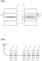
- FIG 6 shows a state in which the rolling stands 1a to 1d are all configured as four-high stands.
- the continuous casting plant 9 and possibly also the upstream rolling stands 10 are also present when the last rolling stand 1d is configured as a six-high stand.
- the working rolls 3, 6 can be axially displaceable - both in the configuration as a four-high stand and in the configuration as a six-high stand.
- the intermediate rolls 7 can also be displaceable relative to the work rolls 6.
- the bending of the work rolls 3, 6 and optionally also of the intermediate rolls 7 can also be as in the prior art.
- the work rolls 3 can be arranged slightly offset relative to the support rolls 4, as seen in the transport direction x of the metal strips 2, 5.
- the last rolling stand 1d When the last rolling stand 1d is configured as a six-high stand, when the work rolls 6 are arranged slightly offset relative to the intermediate rolls 7, as seen in the transport direction x of the metal strips 2, 5. Likewise, when the last rolling stand 1d is configured as a six-high stand, the intermediate rolls 7 can be arranged slightly offset relative to the support rolls 4, as seen in the transport direction x of the metal strips 2, 5. The offset of the work rolls 6 relative to the intermediate rolls 7 and the offset of the intermediate rolls 7 relative to the support rolls 4 are preferably in the same direction. If necessary, any thrust forces can be absorbed by support rollers.
- the support rollers if present, are arranged on the inlet side and/or outlet side of the work rolls 6. However, such support rollers should be dispensed with if possible.
- the work rolls 3, 6 are generally cooled both in the four-high stand configuration and in the six-high stand configuration.
- Appropriate cooling beams are provided for cooling.
- the cooling beams can be arranged on the inlet side and/or outlet side of the cassette 8 if necessary.
- the cooling beams can be a component of the last rolling stand 1d as such, so that they are not installed or removed when the configuration of the last rolling stand 1d is changed.
- the present invention has many advantages. For example, due to the smaller diameter D' of the work rolls 6 compared to the diameter D of the work rolls 3, not only metal strips 2, 5 made of softer materials, but also metal strips 2, 5 made of harder materials can be rolled to low final thicknesses. Subsequent cold rolling can be omitted or can begin with a thinner input product, which in turn means that the output product of the cold rolling can have a lower thickness. Nevertheless, the range of products that can be produced is not impaired, and is often even expanded. In particular, for larger final thicknesses, the required bending stiffness during rolling can be achieved by configuring the last rolling stand 1d as a four-high stand.
- the pass reduction in the last rolling stand 1d can be maximized in the configuration as a six-high stand, although the rolling forces and rolling moments required for this can still be reduced.
- This also makes it possible to achieve improved material properties of the second metal strip 5.
- the microstructure of the second metal strip 5 can be homogenized and so-called shear bands can be prevented.
- ferritic rolling is possible in the hot rolling mill. This can have a positive effect on the so-called r-value, which characterizes the planar anisotropy and is important for the deep-drawability of the rolled metal strips 2, 5. In the prior art, this requires cold rolling followed by annealing.
- the present invention eliminates the need for cold rolling and annealing.
Landscapes
- Engineering & Computer Science (AREA)
- Mechanical Engineering (AREA)
- Metal Rolling (AREA)
Description
- Die vorliegende Erfindung geht aus von einem Betriebsverfahren für eine Warmwalzstraße, die zumindest ein erstes und ein letztes Walzgerüst aufweist,
- wobei in der Warmwalzstraße nacheinander ein erstes und ein zweites Metallband gewalzt werden,
- wobei Abschnitte der Metallbänder jeweils zuerst das erste und erst danach das letzte Walzgerüst der Warmwalzstraße durchlaufen,
- wobei das letzte Walzgerüst zwischen dem Walzen des ersten Metallbandes und dem Walzen des zweiten Metallbandes umgerüstet wird,
- wobei das erste Walzgerüst sowohl während des Walzens des ersten Metallbandes als auch während des Walzens des zweiten Metallbandes als Quartogerüst konfiguriert ist,
- wobei die Warmwalzstraße zwischen dem ersten und dem letzten Walzgerüst eine Anzahl von weiteren Walzgerüsten aufweist.
- Die oben genannten Gegenstände sind allgemein bekannt. Insbesondere werden Fertigstraßen zum Walzen von Metallbändern (insbesondere aus Stahl) üblicherweise auf diese Art und Weise betrieben und sind Fertigstraßen zum Walzen von Metallbändern (insbesondere aus Stahl) üblicherweise derart ausgebildet. Das Umrüsten des letzten Walzgerüsts (und in der Regel auch der anderen Walzgerüste der Fertigstraße) erfolgt, um verschlissene Arbeitswalzen und gegebenenfalls auch verschlissene Stützwalzen auszutauschen. Die Konfiguration der Walzgerüste wird hierbei nicht geändert. Es erfolgt lediglich ein Austausch 1:1 von Walzenpaaren.
- Die Walzgerüste von Warmwalzstraßen sind in aller Regel als sogenannte Quartogerüste ausgebildet. Quartogerüste sind Walzgerüste, die zusätzlich zu den Arbeitswalzen Stützwalzen aufweisen, an denen sich die Arbeitswalzen abstützen. Im englischen Sprachraum werden derartige Walzgerüste oftmals auch als 4-high bezeichnet.
- Beim Warmwalzen geht der Trend insbesondere auch bei Materialien mit hoher Festigkeit zu immer geringeren Enddicken. Beispielsweise kann bei modernen Gießwalzanlagen bei weichen Güten bereits eine Banddicke von deutlich unter 1 mm produziert werden, teilweise sogar von nur 0,6 mm. Bei festeren Materialien können derartige Enddicken nicht realisiert werden. Denn hierfür werden in der Praxis Arbeitswalzen mit einem sehr kleinen Durchmesser benötigt. Durch die Durchmesser der heute verwendeten Arbeitswalzen ist man bei den Enddicken jedoch begrenzt. Insbesondere sinkt mit sinkendem Arbeitswalzendurchmesser auch das übertragbare Drehmoment. Weiterhin muss in hinreichendem Umfang ein Kühlmittel auf die Arbeitswalzen aufgebracht werden können, damit die Warmwalzstraße im Endlos-Betrieb betrieben werden kann.
- Üblicherweise wird das Problem dadurch gelöst, dass Arbeitswalzen mit einem möglichst kleinen Durchmesser verwendet werden. Je kleiner der Durchmesser der Arbeitswalzen ist, desto geringer ist jedoch auch das Drehmoment, mit dem die Arbeitswalzen angetrieben werden können, ohne einen Bruch des Walzenzapfens zu riskieren. Das Drehmoment ist bei härteren Materialien höher. Es ergibt sich dadurch das Problem, dass einerseits der Durchmesser der Arbeitswalzen möglichst klein sein sollte, um eine möglichst geringe Enddicke erreichen zu können, andererseits aber nicht zu klein werden darf, da anderenfalls das erforderliche Drehmoment nicht übertragen werden kann.
- Beim Kaltwalzen wird das Problem durch Walzgerüste gelöst, die eine Vielzahl an Walzen aufweisen, beispielsweise sogenannte 12-Rollen-Walzgerüste oder 20-Rollen-Walzgerüste. Derartige Walzgerüste können beim Warmwalzen nicht eingesetzt werden, da sie zu viel Platz einnehmen und keine hinreichende Kühlung der Walzen - insbesondere der Arbeitswalzen - zulassen.
- Aus der
US 2006/0 010 952 A1 ist bekannt, bei einer Kaltwalzstraße einzelne Walzgerüste umrüstbar auszugestalten, so dass sie nach Bedarf als Quartogerüste oder als Sextogerüste konfiguriert sein können. Sextogerüste sind Walzgerüste, die zusätzlich zu den Arbeitswalzen und den Stützwalzen auch noch Zwischenwalzen aufweisen, wobei die Arbeitswalzen sich an den Zwischenwalzen abstützen und die Zwischenwalzen sich an den Stützwalzen abstützen. Im englischen Sprachraum werden derartige Walzgerüste oftmals auch als 6-high bezeichnet. - Aus der
US 2006/0 196 243 A1 ist ebenfalls bekannt, ein Walzgerüst umrüstbar auszugestalten, so dass es nach Bedarf als Quartogerüst oder als Sextogerüst konfiguriert sein kann. Das Walzgerüst derUS 2006/0 196 243 A1 scheint ebenfalls ein Kaltwalzgerüst zu sein. - Aus der
JP 63 013 603 A - Aus der
WO 2018/167 710 A1 ist eine Walzanlage bekannt, die drei sequenziell aufeinanderfolgende Walzstraßen aufweist. Die erste Walzstraße ist eine Vorstraße und weist als Walzgerüste Quartogerüste auf. Die zweite Walzstraße ist eine Fertigstraße und weist als Walzgerüste ebenfalls Quartogerüste auf. Die dritte Walzstraße schließt sich an die Fertigstraße an, wobei zwischen der Fertigstraße und der dritten Walzstraße Temperaturbeeinflussungseinrichtungen angeordnet sind. Die dritte Walzstraße weist als Walzgerüste Quartogerüste oder Sextogerüste auf. Der Oberbegriff von Anspruch 1 basiert auf diesem Dokument. - Aus der
EP 0 281 782 A2 ist bekannt, bei einem als Sextogerüst ausgebildeten Walzgerüst die Arbeitswalzen und die Zwischenwalzen durch dicke Arbeitswalzen zu ersetzen und das Walzgerüst sodann als Duogerüst oder als Quartogerüst zu betreiben. - Aus der
US 2 039 959 A ist ein als Sextogerüst ausgebildetes Walzgerüst bekannt, das nach Ausbau der Arbeitswalzen als Quartogerüst betrieben werden kann. In diesem Zustand dienen die Zwischenwalzen als Arbeitswalzen. - Die Aufgabe der vorliegenden Erfindung besteht darin, Möglichkeiten zu schaffen, in einer Warmwalzstraße auch Materialien mit höheren Festigkeit mit geringen Enddicken herstellen zu können.
- Die Aufgabe wird durch ein Betriebsverfahren für eine Warmwalzstraße mit den Merkmalen des Anspruchs 1 gelöst. Vorteilhafte Ausgestaltungen des Betriebsverfahrens sind Gegenstand der abhängigen Ansprüche 2 bis 5.
- Erfindungsgemäß wird ein Betriebsverfahren der eingangs genannten Art dadurch ausgestaltet, dass im Rahmen der Umrüstung des letzten Walzgerüsts das letzte Walzgerüst zwischen dem Walzen des ersten Metallbandes und dem Walzen des zweiten Metallbandes von einem Quartogerüst zu einem Sextogerüst oder umgekehrt umgerüstet wird, so dass das letzte Walzgerüst während des Walzens des ersten Metallbandes als Quartogerüst mit Arbeitswalzen und Stützwalzen konfiguriert ist und während des Walzens des zweiten Metallbandes als Sextogerüst mit Arbeitswalzen, Zwischenwalzen und Stützwalzen konfiguriert ist, und dass die weiteren Walzgerüste sowohl während des Walzens des ersten Metallbandes als auch während des Walzens des zweiten Metallbandes als Quartogerüste konfiguriert sind.
- Durch diese Umrüstung es möglich, ein Metallband aus einem weicheren Material zu walzen oder ein Metallband auf eine größere Enddicke zu walzen, während das letzte Walzgerüst - wie im Stand der Technik auch - als Quartogerüst konfiguriert ist. Wenn jedoch ein Metallband aus einem härteren Material auf eine kleine Enddicke gewalzt werden soll, kann erfindungsgemäß eine Umrüstung des letzten Walzgerüsts zu einem Sextogerüst erfolgen.
- Es ist möglich, den Walzplan (d.h. die Abfolge der nacheinander zu walzenden Metallbänder) derart zu erstellen, dass die Umrüstung des letzten Walzgerüsts zu einem Zeitpunkt erfolgt, zu dem aufgrund des Verschleißes der momentan im letzten Walzgerüst befindlichen Arbeitswalzen die Arbeitswalzen sowieso ausgebaut werden müssten. Diese Vorgehensweise führt zu einer optimierten Produktivität. Prinzipiell ist die Umrüstung aber auch unabhängig vom Verschleißzustand der Arbeitswalzen und damit unabhängig von einem durch Verschleiß bedingten Austausch der Arbeitswalzen (bei einem Quartogerüst) oder der Arbeitswalzen und gegebenenfalls auch der Zwischenwalzen (bei einem Sextogerüst) realisierbar.
- Vorzugsweise entspricht die Summe der Durchmesser von Arbeitswalzen und Zwischenwalzen des als Sextogerüst konfigurierten letzten Walzgerüsts zumindest in etwa - nämlich auf 20 % genau, besser auf 10 % genau - dem Durchmesser der Arbeitswalzen des als Quartogerüst konfigurierten letzten Walzgerüsts. Dadurch kann der Stellbereich des letzten Walzgerüsts sowohl in der Konfiguration als Quartogerüst als auch in der Konfiguration als Sextogerüst optimal ausgenutzt werden.
- Das Umrüsten des letzten Walzgerüsts von einem Quartogerüst zu einem Sextogerüst erfolgt vorzugsweise durch Ausbauen von Arbeitswalzen des als Quartogerüst konfigurierten letzten Walzgerüsts und Einbauen von Arbeitswalzen und Zwischenwalzen des als Sextogerüst konfigurierten letzten Walzgerüsts. Umgekehrt erfolgt das Umrüsten des letzten Walzgerüsts von einem Sextogerüst zu einem Quartogerüst vorzugsweise durch Ausbauen der Arbeitswalzen und der Zwischenwalzen des als Sextogerüst konfigurierten letzten Walzgerüsts und Einbauen der Arbeitswalzen des als Quartogerüst konfigurierten letzten Walzgerüsts.
- Vorzugsweise werden beim Umrüsten des letzten Walzgerüsts von einem Quartogerüst zu einem Sextogerüst oder umgekehrt die Arbeitswalzen und die Zwischenwalzen des als Sextogerüst konfigurierten letzten Walzgerüsts als Einheit eingebaut oder ausgebaut. Dadurch kann die Umrüstung besonders schnell erfolgen.
- Vorliegend weist die Warmwalzstraße zwischen dem ersten und dem letzten Walzgerüst eine Anzahl von weiteren Walzgerüsten auf, beispielsweise zwei weitere Walzgerüste, drei weitere Walzgerüste oder vier weitere Walzgerüste, so dass - einschließlich des ersten Walzgerüsts und des letzten Walzgerüsts - insgesamt vier, fünf oder sechs Walzgerüste vorhanden sind. Vorliegend sind die weiteren Walzgerüste sowohl während des Walzens des ersten Metallbandes als auch während des Walzens des zweiten Metallbandes als Quartogerüste konfiguriert. Es erfolgt also ausschließlich eine Umrüstung des letzten Walzgerüsts.
- Es ist möglich, dass die Arbeitswalzen des als Sextogerüst konfigurierten letzten Walzgerüsts angetrieben sind. In diesem Fall weisen diese Arbeitswalzen vorzugsweise einen Durchmesser auf, der mindestens so groß wie der Durchmesser der Zwischenwalzen des als Sextogerüst konfigurierten letzten Walzgerüsts ist. Alternativ ist es möglich, dass die Zwischenwalzen des als Sextogerüst konfigurierten letzten Walzgerüsts angetrieben sind. In diesem Fall weisen die Arbeitswalzen des als Sextogerüst konfigurierten letzten Walzgerüsts vorzugsweise einen Durchmesser auf, der zwischen 50 % und 70 % des Durchmessers der Zwischenwalzen des als Sextogerüst konfigurierten letzten Walzgerüsts liegt.
- Die oben beschriebenen Eigenschaften, Merkmale und Vorteile dieser Erfindung sowie die Art und Weise, wie diese erreicht werden, werden klarer und deutlicher verständlich im Zusammenhang mit der folgenden Beschreibung der Ausführungsbeispiele, die in Verbindung mit den Zeichnungen näher erläutert werden. Hierbei zeigen in schematischer Darstellung:
- FIG 1
- eine Warmwalzstraße während des Walzens eines ersten Metallbandes,
- FIG 2
- die Warmwalzstraße von
FIG 1 während eines nicht erfindungsgemäßen Walzens eines zweiten Metallbandes, - FIG 3
- den Ausbau von Arbeitswalzen aus einem letzten Walzgerüst der Warmwalzstraße,
- FIG 4
- den Einbau von Arbeitswalzen und Zwischenwalzen in das letzte Walzgerüst der Warmwalzstraße,
- FIG 5
- das letzte Walzgerüst der Warmwalzstraße in zwei verschiedenen Konfigurationen und
- FIG 6
- eine Modifikation der Warmwalzstraße von
FIG 1 . - Gemäß
FIG 1 weist eine Warmwalzstraße mehrere Walzgerüste 1a bis 1d auf. Die Warmwalzstraße kann insbesondere als Fertigstraße ausgebildet sein. - Gemäß
FIG 1 sind vier Walzgerüste 1a bis 1d vorhanden. Die Anzahl an Walzgerüsten 1a bis 1d könnte jedoch auch größer sein, beispielsweise fünf, sechs oder sieben. Mindestens sind aber drei Walzgerüste 1a bis 1d vorhanden. Somit ist zwischen dem ersten Walzgerüst 1a und dem letzten Walzgerüst 1d eine Anzahl von weiteren Walzgerüsten 1b, 1c angeordnet. - In der Warmwalzstraße wird zu einem bestimmten Zeitpunkt ein erstes Metallband 2 warmgewalzt. Das erste Metallband 2 kann insbesondere ein Stahlband sein. Das erste Metallband 2 durchläuft die Warmwalzstraße ohne Stoppen und ohne Richtungsumkehr in einer Transportrichtung x. Die einzelnen Abschnitte des ersten Metallbandes 2 durchlaufen somit zunächst das erste Walzgerüst 1a, danach das zweite Walzgerüst 1b, dann das dritte Walzgerüst 1c und schließlich das letzte Walzgerüst 1d. Vor dem Walzen im ersten Walzgerüst 1a kann das erste Metallband 2 beispielsweise in einem Ofen (nicht dargestellt) auf die erforderliche Walztemperatur aufgeheizt werden. Die Walztemperatur liegt bei einem Stahlband meist zwischen 900 °C und 1200 °C. Nach dem Walzen im letzten Walzgerüst 1d kann das erste Metallband 2 beispielsweise zu einem Coil (nicht dargestellt) aufgehaspelt werden.
- In dem in
FIG 1 dargestellten Zustand, also während des Walzens des ersten Metallbandes 2, sind alle Walzgerüste 1a bis 1d der Warmwalzstraße als Quartogerüste konfiguriert. Die Walzgerüste 1a bis 1d weisen also jeweils Arbeitswalzen 3 und Stützwalzen 4 auf, aber keine weiteren Walzen. Dies gilt insbesondere auch für das erste und das letzte Walzgerüst 1a, 1d der Warmwalzstraße. -
FIG 2 zeigt dieselbe Warmwalzstraße mit denselben Walzgerüsten 1a bis 1d während des Walzens eines zweiten Metallbandes 5. Entsprechend der Darstellung inFIG 2 ist das erste Walzgerüst 1a zu diesem Zeitpunkt, also während des Walzens des zweiten Metallbandes 5, weiterhin als Quartogerüst konfiguriert. Zumindest das letzte Walzgerüst 1d ist jedoch als Sextogerüst konfiguriert. Es weist also zusätzlich zu den Stützwalzen 4 Arbeitswalzen 6 und Zwischenwalzen 7 auf. Die Zwischenwalzen 7 sind zwischen den Stützwalzen 4 und den Arbeitswalzen 6 angeordnet. - Die weiteren Walzgerüste 1b, 1c sind entsprechend der Darstellung in
FIG 2 auch während des Walzens des zweiten Metallbandes 5 weiterhin als Quartogerüste konfiguriert. - Bei einem Quartogerüst sind in der Regel die Arbeitswalzen 3 angetrieben. Bei einem Sextogerüst sind in der Regel ebenfalls die Arbeitswalzen 6 angetrieben. Zusätzlich oder alternativ - im Regelfall alternativ - können bei einem Sextogerüst jedoch auch die Zwischenwalzen 7 angetrieben sein. Diese Aussagen gelten im Falle der jeweiligen Konfiguration auch für das letzte Walzgerüst 1d der Warmwalzstraße.
- Nachfolgend wird angenommen, dass in der Warmwalzstraße zuerst das erste Metallband 2 gewalzt wird und erst danach das zweite Metallband 5 gewalzt wird. Prinzipiell ist aber auch die umgekehrte Vorgehensweise möglich.
- Um in derselben Warmwalzstraße sowohl das erste Metallband 2 als auch das zweite Metallband 5 walzen zu können, wird zwischen dem Walzen des ersten Metallbandes 2 und dem Walzen des zweiten Metallbandes 5 das letzte Walzgerüst 1d von einem Quartogerüst zu einem Sextogerüst umgerüstet. Es werden also entsprechend der Darstellung in
FIG 3 , ausgehend von der Konfiguration des letzten Walzgerüsts 1d als Quartogerüst, die Arbeitswalzen 3 des Quartogerüsts ausgebaut. Das Ausbauen erfolgt, wie allgemein üblich und inFIG 3 durch einen Pfeil A angedeutet, in Axialrichtung der Arbeitswalzen 3 durch das Fenster des bedienseitigen Gerüstständers. Gestrichelt sind inFIG 3 die ausgebauten Arbeitswalzen 3 mit dargestellt. - Nach dem Ausbauen der Arbeitswalzen 3 werden entsprechend der Darstellung in
FIG 4 die Arbeitswalzen 6 und die Zwischenwalzen 7 des Sextogerüsts eingebaut. Das Einbauen erfolgt, wie vom Ansatz her allgemein üblich und inFIG 4 durch einen Pfeil B angedeutet, in Axialrichtung der Arbeitswalzen 6 und der Zwischenwalzen 7 durch das Fenster des bedienseitigen Gerüstständers. - Im Ergebnis wird das letzte Walzgerüst 1d somit nach Bedarf entweder als Quartogerüst - siehe in
FIG 5 links - oder als Sextogerüst - siehe inFIG 5 rechts - konfiguriert. - Die Stützwalzen 4 werden beim Umrüsten des letzten Walzgerüsts 1d nicht mit gewechselt. Die Stützwalzen 4 sind also sowohl in der Konfiguration des letzten Walzgerüsts 1d als Quartogerüst als auch in der Konfiguration des letzten Walzgerüsts 1d als Sextogerüst dieselben Stützwalzen 4.
- Vorzugsweise sind entsprechend der Darstellung in
FIG 4 die Arbeitswalzen 6 und die Zwischenwalzen 7 des Sextogerüsts in einer Kassette 8 angeordnet. Dadurch ist es möglich, die Kassette 8 als solche einzubauen, also als Einheit. Auch die Arbeitswalzen 6 und die Zwischenwalzen 7 des Sextogerüsts können damit als Einheit, d.h. insbesondere simultan, eingebaut werden. - Um den Stellbereich des letzten Walzgerüsts 1d - also die Walzspalte, welche zwischen den Arbeitswalzen 3 bzw. zwischen den Arbeitswalzen 6 gebildet werden können - sowohl in der Konfiguration als Quartogerüst als auch in der Konfiguration als Sextogerüst möglichst groß zu halten, sollten die Durchmesser D, D' und D" der Arbeitswalzen 3, der Arbeitswalzen 6 und der Zwischenwalzen 7 vorzugsweise derart aufeinander abgestimmt sein, dass die Summe der Durchmesser D', D" von Arbeitswalzen 6 und Zwischenwalzen 7 des Sextogerüsts dem Durchmesser der Arbeitswalzen 3 des Quartogerüsts zumindest in etwa entspricht. Kleinere Abweichungen von maximal 20 %, besser von maximal 10 %, können jedoch toleriert werden.
- Die Durchmesser D', D" der Arbeitswalzen 6 und der Zwischenwalzen 7 in der Konfiguration des letzten Walzgerüsts 1d als Sextogerüst sollten weiterhin unter Berücksichtigung des Umstands bestimmt werden, ob die Arbeitswalzen 6 oder die Zwischenwalzen 7 angetrieben sind. Im erstgenannten Fall kann der Durchmesser D' der Arbeitswalzen 6 ebenso groß wie der Durchmesser D" der Zwischenwalzen 7 sein, gegebenenfalls sogar größer als der Durchmesser D" der Zwischenwalzen 7. Im letztgenannten Fall ist der Durchmesser D' der Arbeitswalzen 6 vorzugsweise deutlich kleiner als der Durchmesser D" der Zwischenwalzen 7. Beispielsweise kann der Durchmesser D' der Arbeitswalzen 6 zwischen 50 % und 70 % des Durchmessers D" der Zwischenwalzen 7 liegen.
- Obenstehend wurde die Umrüstung des letzten Walzgerüsts 1d von einer Konfiguration als Quartogerüst zu einer Konfiguration als Sextogerüst erläutert. Die umgekehrte Vorgehensweise, also die Umrüstung von einem Sextogerüst zu einem Quartogerüst, ist jedoch ebenso möglich. Es muss lediglich die umgekehrte Vorgehensweise ergriffen werden.
- Entsprechend der Darstellung in
FIG 6 kann die Warmwalzstraße eine Stranggießanlage 9 aufweisen. Die Stranggießanlage 9 ist dem ersten Walzgerüst 1a vorgeordnet. In der Stranggießanlage werden die Metallbänder 2, 5 vor dem Walzen in der Warmwalzstraße gegossen. Es ist daher möglich, die Metallbänder 2, 5 dem ersten Walzgerüst 1a aus der Gießhitze heraus zuzuführen. Die Warmwalzstraße ist somit in diesem Fall zu einer Gieß-Walz-Verbundanlage erweitert. Aufgrund des Vorhandenseins der Stranggießanlage 9 ist es insbesondere möglich, die Warmwalzstraße im Endlos-Betrieb zu betreiben. Alternativ ist aber auch ein Batch-Betrieb möglich. Weiterhin ist es möglich, dass die Warmwalzstraße - alternativ oder zusätzlich zur Stranggießanlage 9 - einen Ofen aufweist (in den FIG nicht dargestellt). Der Ofen ist, sofern er vorhanden ist, dem ersten Walzgerüst 1a vorgeordnet. Nach Bedarf können dem ersten Walzgerüst 1a weiterhin vorgeordnete Walzgerüste 10 vorgeordnet sein, insbesondere Vorgerüste einer Vorstraße. Die vorgeordneten Walzgerüste 10 sind, sofern sie vorhanden sind, der Stranggießanlage 9 und/oder dem Ofen nachgeordnet. -
FIG 6 zeigt einen Zustand, in dem die Walzgerüste 1a bis 1d alle als Quartogerüst konfiguriert sind. Die Stranggießanlage 9 und gegebenenfalls auch die vorgeordneten Walzgerüste 10 sind aber auch dann vorhanden, wenn das letzte Walzgerüst 1d als Sextogerüst konfiguriert ist. - Weitere Ausgestaltungen der Walzgerüste 1a bis 1d können nach Bedarf sein. Insbesondere können - sowohl in der Konfiguration als Quartogerüst als auch in der Konfiguration als Sextogerüst - die Arbeitswalzen 3, 6 axial verschiebbar sein. In der Konfiguration als Sextogerüst können alternativ oder zusätzlich zu den Arbeitswalzen 6 auch die Zwischenwalzen 7 verschiebbar sein. Auch die Biegung der Arbeitswalzen 3, 6 und gegebenenfalls auch der Zwischenwalzen 7 kann so wie im Stand der Technik auch sein. Weiterhin können in Transportrichtung x der Metallbänder 2, 5 gesehen in der Konfiguration der Walzgerüste 1a bis 1d als Quartogerüst die Arbeitswalzen 3 leicht gegenüber den Stützwalzen 4 versetzt angeordnet sein. In der Konfiguration des letzten Walzgerüsts 1d als Sextogerüst können in Transportrichtung x der Metallbänder 2, 5 gesehen die Arbeitswalzen 6 leicht gegenüber den Zwischenwalzen 7 versetzt angeordnet sein. Ebenso können in Transportrichtung x der Metallbänder 2, 5 gesehen in der Konfiguration des letzten Walzgerüsts 1d als Sextogerüst die Zwischenwalzen 7 leicht gegenüber den Stützwalzen 4 versetzt angeordnet sein. Der Versatz der Arbeitswalzen 6 gegenüber den Zwischenwalzen 7 und der Versatz der Zwischenwalzen 7 gegenüber den Stützwalzen 4 sind vorzugsweise gleichgerichtet. Soweit erforderlich, können etwaige Schubkräfte durch Stützrollen aufgefangen werden. Die Stützrollen sind, sofern sie vorhanden sind, einlaufseitig und/oder auslaufseitig der Arbeitswalzen 6 angeordnet. Nach Möglichkeit sollte auf derartige Stützrollen jedoch verzichtet werden.
- Beim letzten Walzgerüst 1d werden sowohl in der Konfiguration als Quartogerüst als auch in der Konfiguration als Sextogerüst die Arbeitswalzen 3, 6 in aller Regel gekühlt. Zur Kühlung sind entsprechende Kühlbalken vorhanden. Für die Kühlung der Arbeitswalzen 6 in der Konfiguration als Sextogerüst können die Kühlbalken gegebenenfalls einlaufseitig und/oder auslaufseitig an der Kassette 8 angeordnet sein. Alternativ können die Kühlbalken ein Bestandteil des letzten Walzgerüsts 1d als solches sein, so dass sie beim Umrüsten der Konfiguration des letzten Walzgerüsts 1d nicht mit ein- und ausgebaut werden.
- Die vorliegende Erfindung weist viele Vorteile auf. So können aufgrund des geringeren Durchmessers D' der Arbeitswalzen 6 gegenüber dem Durchmesser D der Arbeitswalzen 3 beispielsweise nicht nur Metallbänder 2, 5 aus weicheren Materialien, sondern auch Metallbänder 2, 5 aus härteren Materialien auf geringe Enddicken gewalzt werden. Ein nachfolgendes Kaltwalzen kann entfallen oder mit einem dünneren Eingangsprodukt beginnen, wodurch dann wiederum das Ausgangsprodukt des Kaltwalzens eine geringere Dicke aufweisen kann. Dennoch wird das herstellbare Produktspektrum nicht beeinträchtigt, oftmals sogar erweitert. Insbesondere kann für größere Enddicken die erforderliche Biegesteifigkeit beim Walzen dadurch erreicht werden, dass das letzte Walzgerüst 1d als Quartogerüst konfiguriert wird. Die Stichabnahme im letzten Walzgerüst 1d kann in der Konfiguration als Sextogerüst maximiert werden, wobei dennoch die hierfür erforderlichen Walzkräfte und Walzmomente reduziert werden können. Dadurch können zugleich auch verbesserte Materialeigenschaften des zweiten Metallbandes 5 erreicht werden. Insbesondere kann die Mikrostruktur des zweiten Metallbandes 5 homogenisiert werden und können sogenannte Scherbänder verhindert werden. Schließlich ist ein ferritisches Walzen in der Warmwalzstraße möglich. Dadurch kann der sogenannte r-Wert, der die planare Anisotropie charakterisiert und für die Tiefziehfähigkeit der gewalzten Metallbändern 2, 5 von Bedeutung ist, positiv beeinflusst werden. Im Stand der Technik ist hierfür ein Kaltwalzen mit nachfolgendem Glühen erforderlich. Durch die vorliegende Erfindung können das Kaltwalzen und das Glühen entfallen.
-
- 1a bis 1d
- Walzgerüste
- 2, 5
- Metallbänder
- 3, 6
- Arbeitswalzen
- 4
- Stützwalzen
- 7
- Zwischenwalzen
- 8
- Kassette
- 9
- Stranggießanlage
- 10
- vorgeordnete Walzgerüste
- A, B
- Pfeile
- D, D', D"
- Durchmesser
- x
- Transportrichtung
Claims (5)
- Betriebsverfahren für eine Warmwalzstraße, die zumindest ein erstes und ein letztes Walzgerüst (1a, 1d) aufweist,- wobei in der Warmwalzstraße nacheinander ein erstes und ein zweites Metallband (2, 5) gewalzt werden,- wobei Abschnitte der Metallbänder (2, 5) jeweils zuerst das erste und erst danach das letzte Walzgerüst (1a, 1d) der Warmwalzstraße durchlaufen,- wobei das erste Walzgerüst (1a) sowohl während des Walzens des ersten Metallbandes (2) als auch während des Walzens des zweiten Metallbandes (5) als Quartogerüst konfiguriert ist,- wobei die Warmwalzstraße zwischen dem ersten und dem letzten Walzgerüst (1a, 1d) eine Anzahl von weiteren Walzgerüsten (1b, 1c) aufweist,dadurch gekennzeichnet,
dass das letzte Walzgerüst (1d) zwischen dem Walzen des ersten Metallbandes (2) und dem Walzen des zweiten Metallbandes (5) von einem Quartogerüst zu einem Sextogerüst oder umgekehrt umgerüstet wird, so dass das letzte Walzgerüst (1d) während des Walzens des ersten Metallbandes (2) als Quartogerüst mit Arbeitswalzen (3) und Stützwalzen (4) konfiguriert ist und während des Walzens des zweiten Metallbandes (5) als Sextogerüst mit Arbeitswalzen (6), Zwischenwalzen (7) und Stützwalzen (4) konfiguriert ist, und dass die weiteren Walzgerüste (1b, 1c) sowohl während des Walzens des ersten Metallbandes (2) als auch während des Walzens des zweiten Metallbandes (5) als Quartogerüste konfiguriert sind. - Betriebsverfahren nach Anspruch 1,
dadurch gekennzeichnet,
dass die Summe der Durchmesser (D', D") von Arbeitswalzen (6) und Zwischenwalzen (7) des als Sextogerüst konfigurierten letzten Walzgerüsts (1d) auf 20 % genau, vorzugsweise auf 10 % genau, dem Durchmesser (D) der Arbeitswalzen (3) des als Quartogerüst konfigurierten letzten Walzgerüsts (1d) entspricht. - Betriebsverfahren nach Anspruch 1 oder 2,
dadurch gekennzeichnet,
dass das Umrüsten des letzten Walzgerüsts (1d) von einem Quartogerüst zu einem Sextogerüst durch Ausbauen von Arbeitswalzen (3) des als Quartogerüst konfigurierten letzten Walzgerüsts (1d) und Einbauen von Arbeitswalzen (6) und Zwischenwalzen (7) des als Sextogerüst konfigurierten letzten Walzgerüsts (1d) erfolgt bzw. umgekehrt das Umrüsten des letzten Walzgerüsts (1d) von einem Sextogerüst zu einem Quartogerüst durch Ausbauen der Arbeitswalzen (6) und der Zwischenwalzen (7) des als Sextogerüst konfigurierten letzten Walzgerüsts (1d) und Einbauen der Arbeitswalzen (3) des als Quartogerüst konfigurierten letzten Walzgerüsts (1d) erfolgt. - Betriebsverfahren nach Anspruch 3,
dadurch gekennzeichnet,
dass beim Umrüsten des letzten Walzgerüsts (1d) von einem Quartogerüst zu einem Sextogerüst oder umgekehrt die Arbeitswalzen (6) und die Zwischenwalzen (7) des als Sextogerüst konfigurierten letzten Walzgerüsts (1d) als Einheit eingebaut oder ausgebaut werden. - Betriebsverfahren nach einem der obigen Ansprüche,
dadurch gekennzeichnet,
dass die Arbeitswalzen (6) des als Sextogerüst konfigurierten letzten Walzgerüsts (1d) angetrieben sind und einen Durchmesser (D') aufweisen, der mindestens so groß wie der Durchmesser (D") der Zwischenwalzen (7) des als Sextogerüst konfigurierten letzten Walzgerüsts (1d) ist, oder dass die Zwischenwalzen (7) des als Sextogerüst konfigurierten letzten Walzgerüsts (1d) angetrieben sind und die Arbeitswalzen (6) des als Sextogerüst konfigurierten letzten Walzgerüsts (1d) einen Durchmesser (D') aufweisen, der zwischen 50 % und 70 % des Durchmessers der Zwischenwalzen (7) des als Sextogerüst konfigurierten letzten Walzgerüsts (1d) liegt.
Applications Claiming Priority (2)
| Application Number | Priority Date | Filing Date | Title |
|---|---|---|---|
| ATA50442/2019A AT522073B1 (de) | 2019-05-16 | 2019-05-16 | Warmwalzen mit flexibler Konfiguration der Walzgerüste |
| PCT/EP2020/061706 WO2020229159A1 (de) | 2019-05-16 | 2020-04-28 | Warmwalzen mit flexibler konfiguration der walzgerüste |
Publications (3)
| Publication Number | Publication Date |
|---|---|
| EP3969194A1 EP3969194A1 (de) | 2022-03-23 |
| EP3969194B1 true EP3969194B1 (de) | 2024-07-24 |
| EP3969194C0 EP3969194C0 (de) | 2024-07-24 |
Family
ID=70682810
Family Applications (1)
| Application Number | Title | Priority Date | Filing Date |
|---|---|---|---|
| EP20725630.6A Active EP3969194B1 (de) | 2019-05-16 | 2020-04-28 | Warmwalzen mit flexibler konfiguration der walzgerüste |
Country Status (4)
| Country | Link |
|---|---|
| EP (1) | EP3969194B1 (de) |
| CN (1) | CN113811402B (de) |
| AT (1) | AT522073B1 (de) |
| WO (1) | WO2020229159A1 (de) |
Family Cites Families (14)
| Publication number | Priority date | Publication date | Assignee | Title |
|---|---|---|---|---|
| US2039959A (en) * | 1933-12-28 | 1936-05-05 | Mesta Machine Co | Rolling mill |
| GB665186A (en) * | 1949-06-09 | 1952-01-16 | Samuel Fox And Company Ltd | Improvements in rolling mills |
| BR8300010A (pt) * | 1982-01-06 | 1983-08-30 | Hitachi Ltd | Laminador |
| JPS6313603A (ja) * | 1986-07-04 | 1988-01-20 | Hitachi Ltd | 圧延機 |
| DE3707560A1 (de) * | 1987-03-10 | 1988-09-22 | Schloemann Siemag Ag | Walzgeruest |
| DE10046426A1 (de) * | 2000-09-20 | 2002-03-28 | Sms Demag Ag | Kombinierter Antrieb für ein Vierwalzen- bzw. Sechswalzengerüst sowie Betriebsverfahren hierfür |
| WO2002047837A1 (en) * | 2000-12-13 | 2002-06-20 | Hitachi, Ltd. | Roll assembly changing equipment and roll assembly changing method |
| FR2846579B1 (fr) | 2002-11-05 | 2006-05-05 | Vai Clecim | Procede pour elargir la gamme de production d'une installation de laminage de produits metalliques et installation pour la mise en oeuvre du procede |
| FR2851942B1 (fr) * | 2003-03-05 | 2006-04-28 | Procede de changement de configuration d'un laminoir et laminoir perfectionne pour la mise en oeuvre du procede | |
| DE102009037278A1 (de) * | 2009-08-12 | 2011-02-17 | Sms Siemag Ag | Vorrichtung und Verfahren zum Herstellen eines dünnen Warmbandes |
| DE102010014346A1 (de) * | 2010-04-09 | 2011-10-13 | Sms Siemag Ag | Verfahren zum fliegenden Arbeitswalzenwechsel in Gießwalzanlagen und Warmbandstraßen |
| CN102303045B (zh) * | 2011-09-22 | 2013-05-29 | 燕山大学 | 四六辊互换轧机 |
| CN202290723U (zh) * | 2011-09-22 | 2012-07-04 | 燕山大学 | 四六辊互换轧机 |
| IT201700028768A1 (it) * | 2017-03-15 | 2018-09-15 | Danieli Off Mecc | Impianto combinato di colata continua e laminazione di nastri metallici a caldo |
-
2019
- 2019-05-16 AT ATA50442/2019A patent/AT522073B1/de active
-
2020
- 2020-04-28 CN CN202080036464.1A patent/CN113811402B/zh active Active
- 2020-04-28 WO PCT/EP2020/061706 patent/WO2020229159A1/de not_active Ceased
- 2020-04-28 EP EP20725630.6A patent/EP3969194B1/de active Active
Also Published As
| Publication number | Publication date |
|---|---|
| EP3969194A1 (de) | 2022-03-23 |
| AT522073B1 (de) | 2020-08-15 |
| AT522073A4 (de) | 2020-08-15 |
| CN113811402B (zh) | 2024-03-12 |
| CN113811402A (zh) | 2021-12-17 |
| WO2020229159A1 (de) | 2020-11-19 |
| EP3969194C0 (de) | 2024-07-24 |
Similar Documents
| Publication | Publication Date | Title |
|---|---|---|
| DE69411971T2 (de) | Warmwalzwerk für Stahlblech und Walzverfahren | |
| DE4402402B4 (de) | Verfahren zur Herstellung von warmgewalztem Stahlband aus stranggegossenem Vormaterial und Anlage zur Durchführung des Verfahrens | |
| DE69209043T2 (de) | Walzwerk, Walzverfahren und Walzwerksystem | |
| EP0771596A1 (de) | Produktionsanlage zum kontinuierlichen- oder diskontinuierlichen Auswalzen von Warmband | |
| EP0266564B1 (de) | Bandgiessanlage mit nachgeordnetem mehrgerüstigen Kontiwalzwerk | |
| DE69701196T2 (de) | Verfahren zum kontinuierlichen Walzen von Blechen und/oder Bänder und entsprechende kontinuierliche Walzstrasse | |
| EP2437900B1 (de) | Energiesparende walzstrasse und energiesparendes verfahren zum betrieb einer giess-walz-verbundanlage | |
| EP2964404B1 (de) | Verfahren zum herstellen eines metallbandes durch giesswalzen | |
| EP2162245B1 (de) | Walzen eines bandes in einer walzstrasse unter nutzung des letzen gerüsts der walzstrasse als zugverringerer | |
| DE69315099T2 (de) | Tandemwalzsystem und Walzenschrägwalzwerk | |
| AT504782A4 (de) | Verfahren zur herstellung eines warmgewalzten stahlbandes und kombinierte giess- und walzanlage zur durchführung des verfahrens | |
| EP2566989B1 (de) | Verfahren zum warmwalzen von stahlbändern und warmwalzstrasse | |
| EP3341142B1 (de) | Verfahren zum betreiben einer anlage nach dem csp-konzept | |
| EP2427281B1 (de) | Verfahren zum herstellen eines in einer walzstrasse einer walzanlage gewalzten walzguts, steuer- und/oder regeleinrichtung für eine walzanlage zur herstellung von gewalztem walzgut, walzanlage zur herstellung von gewalztem walzgut, maschinenlesbarer programmcode und speichermedium | |
| EP2293889B1 (de) | Konti-walzstrasse mit ein- und/oder ausgliedern von walzgerüsten im laufenden betrieb | |
| DE69607781T2 (de) | Warmbandwalzanlage | |
| EP1414596B1 (de) | Warmwalzanlage | |
| DE69623343T2 (de) | Walzwerk, walzverfahren und walzanlage | |
| EP4072747B1 (de) | Warmwalzgerüst für ein warmwalzwerk und zum herstellen eines metallenen flachprodukts, warmwalzwerk sowie verfahren zum betreiben eines warmwalzwerks | |
| EP3969194B1 (de) | Warmwalzen mit flexibler konfiguration der walzgerüste | |
| DE4009860C2 (de) | Verfahren und Anlage zur Herstellung von warmgewalztem Stahlband, insbesondere für Edelstähle, aus bandförmig stranggegossenem Vormaterial | |
| EP0761325A1 (de) | Verfahren und Anlage zur Herstellung von ferritisch warmgewalztem Band | |
| DE69226690T3 (de) | Sechs-walzen-walzwerk | |
| EP3536411A1 (de) | Vermeidung von verschleisskanten beim walzen von flachem walzgut | |
| DE10257971A1 (de) | Mehrwalzengerüst zum Walzen eines Metallbandes |
Legal Events
| Date | Code | Title | Description |
|---|---|---|---|
| STAA | Information on the status of an ep patent application or granted ep patent |
Free format text: STATUS: UNKNOWN |
|
| STAA | Information on the status of an ep patent application or granted ep patent |
Free format text: STATUS: THE INTERNATIONAL PUBLICATION HAS BEEN MADE |
|
| PUAI | Public reference made under article 153(3) epc to a published international application that has entered the european phase |
Free format text: ORIGINAL CODE: 0009012 |
|
| STAA | Information on the status of an ep patent application or granted ep patent |
Free format text: STATUS: REQUEST FOR EXAMINATION WAS MADE |
|
| 17P | Request for examination filed |
Effective date: 20211216 |
|
| AK | Designated contracting states |
Kind code of ref document: A1 Designated state(s): AL AT BE BG CH CY CZ DE DK EE ES FI FR GB GR HR HU IE IS IT LI LT LU LV MC MK MT NL NO PL PT RO RS SE SI SK SM TR |
|
| DAV | Request for validation of the european patent (deleted) | ||
| DAX | Request for extension of the european patent (deleted) | ||
| STAA | Information on the status of an ep patent application or granted ep patent |
Free format text: STATUS: EXAMINATION IS IN PROGRESS |
|
| 17Q | First examination report despatched |
Effective date: 20230404 |
|
| GRAP | Despatch of communication of intention to grant a patent |
Free format text: ORIGINAL CODE: EPIDOSNIGR1 |
|
| STAA | Information on the status of an ep patent application or granted ep patent |
Free format text: STATUS: GRANT OF PATENT IS INTENDED |
|
| INTG | Intention to grant announced |
Effective date: 20240312 |
|
| GRAS | Grant fee paid |
Free format text: ORIGINAL CODE: EPIDOSNIGR3 |
|
| GRAA | (expected) grant |
Free format text: ORIGINAL CODE: 0009210 |
|
| STAA | Information on the status of an ep patent application or granted ep patent |
Free format text: STATUS: THE PATENT HAS BEEN GRANTED |
|
| AK | Designated contracting states |
Kind code of ref document: B1 Designated state(s): AL AT BE BG CH CY CZ DE DK EE ES FI FR GB GR HR HU IE IS IT LI LT LU LV MC MK MT NL NO PL PT RO RS SE SI SK SM TR |
|
| REG | Reference to a national code |
Ref country code: GB Ref legal event code: FG4D Free format text: NOT ENGLISH |
|
| REG | Reference to a national code |
Ref country code: CH Ref legal event code: EP |
|
| REG | Reference to a national code |
Ref country code: DE Ref legal event code: R096 Ref document number: 502020008673 Country of ref document: DE |
|
| REG | Reference to a national code |
Ref country code: IE Ref legal event code: FG4D Free format text: LANGUAGE OF EP DOCUMENT: GERMAN |
|
| U01 | Request for unitary effect filed |
Effective date: 20240724 |
|
| U07 | Unitary effect registered |
Designated state(s): AT BE BG DE DK EE FI FR IT LT LU LV MT NL PT SE SI Effective date: 20240730 |
|
| PG25 | Lapsed in a contracting state [announced via postgrant information from national office to epo] |
Ref country code: NO Free format text: LAPSE BECAUSE OF FAILURE TO SUBMIT A TRANSLATION OF THE DESCRIPTION OR TO PAY THE FEE WITHIN THE PRESCRIBED TIME-LIMIT Effective date: 20241024 |
|
| PG25 | Lapsed in a contracting state [announced via postgrant information from national office to epo] |
Ref country code: GR Free format text: LAPSE BECAUSE OF FAILURE TO SUBMIT A TRANSLATION OF THE DESCRIPTION OR TO PAY THE FEE WITHIN THE PRESCRIBED TIME-LIMIT Effective date: 20241025 Ref country code: PL Free format text: LAPSE BECAUSE OF FAILURE TO SUBMIT A TRANSLATION OF THE DESCRIPTION OR TO PAY THE FEE WITHIN THE PRESCRIBED TIME-LIMIT Effective date: 20240724 |
|
| PG25 | Lapsed in a contracting state [announced via postgrant information from national office to epo] |
Ref country code: IS Free format text: LAPSE BECAUSE OF FAILURE TO SUBMIT A TRANSLATION OF THE DESCRIPTION OR TO PAY THE FEE WITHIN THE PRESCRIBED TIME-LIMIT Effective date: 20241124 |
|
| PG25 | Lapsed in a contracting state [announced via postgrant information from national office to epo] |
Ref country code: HR Free format text: LAPSE BECAUSE OF FAILURE TO SUBMIT A TRANSLATION OF THE DESCRIPTION OR TO PAY THE FEE WITHIN THE PRESCRIBED TIME-LIMIT Effective date: 20240724 |
|
| PG25 | Lapsed in a contracting state [announced via postgrant information from national office to epo] |
Ref country code: RS Free format text: LAPSE BECAUSE OF FAILURE TO SUBMIT A TRANSLATION OF THE DESCRIPTION OR TO PAY THE FEE WITHIN THE PRESCRIBED TIME-LIMIT Effective date: 20241024 Ref country code: ES Free format text: LAPSE BECAUSE OF FAILURE TO SUBMIT A TRANSLATION OF THE DESCRIPTION OR TO PAY THE FEE WITHIN THE PRESCRIBED TIME-LIMIT Effective date: 20240724 |
|
| PG25 | Lapsed in a contracting state [announced via postgrant information from national office to epo] |
Ref country code: RS Free format text: LAPSE BECAUSE OF FAILURE TO SUBMIT A TRANSLATION OF THE DESCRIPTION OR TO PAY THE FEE WITHIN THE PRESCRIBED TIME-LIMIT Effective date: 20241024 Ref country code: PL Free format text: LAPSE BECAUSE OF FAILURE TO SUBMIT A TRANSLATION OF THE DESCRIPTION OR TO PAY THE FEE WITHIN THE PRESCRIBED TIME-LIMIT Effective date: 20240724 Ref country code: NO Free format text: LAPSE BECAUSE OF FAILURE TO SUBMIT A TRANSLATION OF THE DESCRIPTION OR TO PAY THE FEE WITHIN THE PRESCRIBED TIME-LIMIT Effective date: 20241024 Ref country code: IS Free format text: LAPSE BECAUSE OF FAILURE TO SUBMIT A TRANSLATION OF THE DESCRIPTION OR TO PAY THE FEE WITHIN THE PRESCRIBED TIME-LIMIT Effective date: 20241124 Ref country code: HR Free format text: LAPSE BECAUSE OF FAILURE TO SUBMIT A TRANSLATION OF THE DESCRIPTION OR TO PAY THE FEE WITHIN THE PRESCRIBED TIME-LIMIT Effective date: 20240724 Ref country code: GR Free format text: LAPSE BECAUSE OF FAILURE TO SUBMIT A TRANSLATION OF THE DESCRIPTION OR TO PAY THE FEE WITHIN THE PRESCRIBED TIME-LIMIT Effective date: 20241025 Ref country code: ES Free format text: LAPSE BECAUSE OF FAILURE TO SUBMIT A TRANSLATION OF THE DESCRIPTION OR TO PAY THE FEE WITHIN THE PRESCRIBED TIME-LIMIT Effective date: 20240724 |
|
| PG25 | Lapsed in a contracting state [announced via postgrant information from national office to epo] |
Ref country code: SM Free format text: LAPSE BECAUSE OF FAILURE TO SUBMIT A TRANSLATION OF THE DESCRIPTION OR TO PAY THE FEE WITHIN THE PRESCRIBED TIME-LIMIT Effective date: 20240724 Ref country code: RO Free format text: LAPSE BECAUSE OF FAILURE TO SUBMIT A TRANSLATION OF THE DESCRIPTION OR TO PAY THE FEE WITHIN THE PRESCRIBED TIME-LIMIT Effective date: 20240724 |
|
| PG25 | Lapsed in a contracting state [announced via postgrant information from national office to epo] |
Ref country code: CZ Free format text: LAPSE BECAUSE OF FAILURE TO SUBMIT A TRANSLATION OF THE DESCRIPTION OR TO PAY THE FEE WITHIN THE PRESCRIBED TIME-LIMIT Effective date: 20240724 |
|
| PG25 | Lapsed in a contracting state [announced via postgrant information from national office to epo] |
Ref country code: SK Free format text: LAPSE BECAUSE OF FAILURE TO SUBMIT A TRANSLATION OF THE DESCRIPTION OR TO PAY THE FEE WITHIN THE PRESCRIBED TIME-LIMIT Effective date: 20240724 |
|
| PLBE | No opposition filed within time limit |
Free format text: ORIGINAL CODE: 0009261 |
|
| STAA | Information on the status of an ep patent application or granted ep patent |
Free format text: STATUS: NO OPPOSITION FILED WITHIN TIME LIMIT |
|
| U20 | Renewal fee for the european patent with unitary effect paid |
Year of fee payment: 6 Effective date: 20250430 |
|
| 26N | No opposition filed |
Effective date: 20250425 |
|
| REG | Reference to a national code |
Ref country code: CH Ref legal event code: H13 Free format text: ST27 STATUS EVENT CODE: U-0-0-H10-H13 (AS PROVIDED BY THE NATIONAL OFFICE) Effective date: 20251125 |