EP3968049A1 - Verfahren und einrichtung zur schätzung einer ankunftszeit oder eines abstands zwischen zwei vorrichtungen - Google Patents
Verfahren und einrichtung zur schätzung einer ankunftszeit oder eines abstands zwischen zwei vorrichtungen Download PDFInfo
- Publication number
- EP3968049A1 EP3968049A1 EP21173225.0A EP21173225A EP3968049A1 EP 3968049 A1 EP3968049 A1 EP 3968049A1 EP 21173225 A EP21173225 A EP 21173225A EP 3968049 A1 EP3968049 A1 EP 3968049A1
- Authority
- EP
- European Patent Office
- Prior art keywords
- cnt
- bit
- pattern
- time
- correlation value
- Prior art date
- Legal status (The legal status is an assumption and is not a legal conclusion. Google has not performed a legal analysis and makes no representation as to the accuracy of the status listed.)
- Pending
Links
Images


Classifications
-
- G—PHYSICS
- G01—MEASURING; TESTING
- G01S—RADIO DIRECTION-FINDING; RADIO NAVIGATION; DETERMINING DISTANCE OR VELOCITY BY USE OF RADIO WAVES; LOCATING OR PRESENCE-DETECTING BY USE OF THE REFLECTION OR RERADIATION OF RADIO WAVES; ANALOGOUS ARRANGEMENTS USING OTHER WAVES
- G01S5/00—Position-fixing by co-ordinating two or more direction or position line determinations; Position-fixing by co-ordinating two or more distance determinations
- G01S5/02—Position-fixing by co-ordinating two or more direction or position line determinations; Position-fixing by co-ordinating two or more distance determinations using radio waves
- G01S5/0205—Details
- G01S5/021—Calibration, monitoring or correction
-
- H—ELECTRICITY
- H04—ELECTRIC COMMUNICATION TECHNIQUE
- H04L—TRANSMISSION OF DIGITAL INFORMATION, e.g. TELEGRAPHIC COMMUNICATION
- H04L43/00—Arrangements for monitoring or testing data switching networks
- H04L43/04—Processing captured monitoring data, e.g. for logfile generation
-
- G—PHYSICS
- G01—MEASURING; TESTING
- G01S—RADIO DIRECTION-FINDING; RADIO NAVIGATION; DETERMINING DISTANCE OR VELOCITY BY USE OF RADIO WAVES; LOCATING OR PRESENCE-DETECTING BY USE OF THE REFLECTION OR RERADIATION OF RADIO WAVES; ANALOGOUS ARRANGEMENTS USING OTHER WAVES
- G01S11/00—Systems for determining distance or velocity not using reflection or reradiation
- G01S11/02—Systems for determining distance or velocity not using reflection or reradiation using radio waves
-
- G—PHYSICS
- G01—MEASURING; TESTING
- G01S—RADIO DIRECTION-FINDING; RADIO NAVIGATION; DETERMINING DISTANCE OR VELOCITY BY USE OF RADIO WAVES; LOCATING OR PRESENCE-DETECTING BY USE OF THE REFLECTION OR RERADIATION OF RADIO WAVES; ANALOGOUS ARRANGEMENTS USING OTHER WAVES
- G01S5/00—Position-fixing by co-ordinating two or more direction or position line determinations; Position-fixing by co-ordinating two or more distance determinations
- G01S5/02—Position-fixing by co-ordinating two or more direction or position line determinations; Position-fixing by co-ordinating two or more distance determinations using radio waves
- G01S5/0205—Details
- G01S5/0244—Accuracy or reliability of position solution or of measurements contributing thereto
-
- H—ELECTRICITY
- H04—ELECTRIC COMMUNICATION TECHNIQUE
- H04W—WIRELESS COMMUNICATION NETWORKS
- H04W56/00—Synchronisation arrangements
- H04W56/003—Arrangements to increase tolerance to errors in transmission or reception timing
-
- G—PHYSICS
- G01—MEASURING; TESTING
- G01S—RADIO DIRECTION-FINDING; RADIO NAVIGATION; DETERMINING DISTANCE OR VELOCITY BY USE OF RADIO WAVES; LOCATING OR PRESENCE-DETECTING BY USE OF THE REFLECTION OR RERADIATION OF RADIO WAVES; ANALOGOUS ARRANGEMENTS USING OTHER WAVES
- G01S5/00—Position-fixing by co-ordinating two or more direction or position line determinations; Position-fixing by co-ordinating two or more distance determinations
- G01S5/02—Position-fixing by co-ordinating two or more direction or position line determinations; Position-fixing by co-ordinating two or more distance determinations using radio waves
- G01S5/14—Determining absolute distances from a plurality of spaced points of known location
-
- H—ELECTRICITY
- H04—ELECTRIC COMMUNICATION TECHNIQUE
- H04J—MULTIPLEX COMMUNICATION
- H04J3/00—Time-division multiplex systems
- H04J3/02—Details
- H04J3/06—Synchronising arrangements
- H04J3/0635—Clock or time synchronisation in a network
- H04J3/0685—Clock or time synchronisation in a node; Intranode synchronisation
- H04J3/0697—Synchronisation in a packet node
-
- H—ELECTRICITY
- H04—ELECTRIC COMMUNICATION TECHNIQUE
- H04L—TRANSMISSION OF DIGITAL INFORMATION, e.g. TELEGRAPHIC COMMUNICATION
- H04L7/00—Arrangements for synchronising receiver with transmitter
- H04L7/04—Speed or phase control by synchronisation signals
- H04L7/041—Speed or phase control by synchronisation signals using special codes as synchronising signal
- H04L7/042—Detectors therefor, e.g. correlators, state machines
-
- H—ELECTRICITY
- H04—ELECTRIC COMMUNICATION TECHNIQUE
- H04W—WIRELESS COMMUNICATION NETWORKS
- H04W56/00—Synchronisation arrangements
- H04W56/0055—Synchronisation arrangements determining timing error of reception due to propagation delay
- H04W56/0065—Synchronisation arrangements determining timing error of reception due to propagation delay using measurement of signal travel time
- H04W56/007—Open loop measurement
- H04W56/0075—Open loop measurement based on arrival time vs. expected arrival time
- H04W56/008—Open loop measurement based on arrival time vs. expected arrival time detecting arrival of signal based on received raw signal
Definitions
- the present disclosure relates to distance estimation, between two devices.
- it relates to determining the time of arrival of a signal transmitted from a transmitter to a receiver, and to providing a time-stamp for the arrival time at the receiver.
- One way of localising a receiver such as a Bluetooth receiver, that is to say finding the distance between the receiver and another device which may also be similar a Bluetooth device operating as a transmitter, is by measuring the time of flight of a signal between the transmitter and the receiver.
- An accurate measurement of the time of arrival may be used to "timestamp" a received signal, such as a narrowband localisation packet according to a wireless protocol such as Bluetooth low energy (BLE).
- BLE Bluetooth low energy
- RTT round trip time
- BLE packets (called RTT packets) having a data rate of either 1 Mbps or 2 Mbps are transmitted between an initiator and a reflector, and other RTT packets are transmitted back.
- the RTT packets use pseudo random bit-patterns and as a result they are not guaranteed to have good autocorrelation properties. It is challenging to timestamp the received signal with sufficient precision and accuracy for good localisation (for instance, of the order of 1m).
- a method of estimating a time-of-arrival of a packet received by a receiver comprising: storing a reference bit-pattern; receiving a plurality of samples in a samples-buffer; identifying, in a bit-pattern detector, a matching group of samples having a bit-pattern which matches the reference bit-pattern; and determining, from the matching group of samples in a correlator, a group of three correlation values, comprising a local maximum correlation value, P0, an immediately preceding correlation value, Pm, and an immediately succeeding correlation value Pp; using a polynomial function f( ⁇ ) of the difference, ⁇ , between Pm and Pp to estimate, in an estimation unit, a timing offset T frac , between the local maximum correlation value and a correlation peak; and estimating the time-of-arrival from a time of the local maximum correlation value P0, and T frac .
- the bit pattern detector may use a relatively low precision correlator - which for example may use 6- bit arithmetic.
- the correlator may use a relatively high precision arithmetic such as 10 bit arithmetic. Although such high precision arithmetic is significantly more computationally intense, it may only be required to be performed once a bit pattern has been roughly matched.
- N 3.
- the transformation matrix then has dimensions 9x3, with 27 elements. Such a size of matrix facilitates straightforward computation of f( ⁇ ).
- An accurate timestamp can thereby be derived, which may enable localisation of one device such as an initiator relative to another device such as a reflector to within approximately 1m.
- the method further comprises estimating a distance between the receiver and a transmitter from which the packet is received, based on the time-stamp
- the received packet is modulated according to a Gaussian Frequency Shift Key, GFSK, modulation scheme.
- the bit-rate of the GFSK may be 1 MHz, and the received signal may be sampled at 4 MHz sampling rate, for instance, in embodiments in which the receiver is a Bluetooth receive, operating under a so-called HADM (high accuracy distance measurement) protocol.
- the receiver may be operating under a different protocol, and/or the receiver may use a different sampling rate and/or a different modulation rate.
- a time-stamp module for a transceiver and comprising: a samples buffer; a stored reference bit-pattern; a bit-pattern detector comprising a relatively low-precision correlator, configured to identify a set of samples having a bit-pattern which matches the reference bit-pattern; a relatively high-precision correlator configured to determine, from the set of samples, a group of three correlation values, comprising a local maximum correlation value, P0, an immediately preceding correlation value, Pm, and an immediately succeeding correlation value Pp, and an estimation unit configured to use a polynomial function f( ⁇ ) of the difference, ⁇ , between Pm and Pp to estimate a timing offset between a timing of the local maximum correlation value and a correlation peak, and P0, Pm, and Pm.
- the time-stamp module is further configured to estimate a distance between the receiver and a transmitter from which the packet is received, based on the time-offset, a local time of the local maximum correlation value, and a process time.
- a transceiver comprising a time-stamp module as just described, a Gaussian Frequency Shift Key, GFSK, modulator and a GFSK demodulator.
- the transceiver may be a Bluetooth transceiver.
- the skilled person will appreciate that the methods and apparatus described hereinunder are not limited to Bluetooth devices and Bluetooth transmission protocol, but may be equally applicable to other devices or transmission protocols, in which autocorrelation of a modulated pseudo-random bit-pattern can be applied for localisation.
- a computer program which when run on a computer, causes the computer to configure any apparatus, including a circuit, controller, sensor, filter, or device disclosed herein or perform any method disclosed herein.
- the computer program may be a software implementation, and the computer may be considered as any appropriate hardware, including a digital signal processor, a microcontroller, and an implementation in read only memory (ROM), erasable programmable read only memory (EPROM) or electronically erasable programmable read only memory (EEPROM), as non-limiting examples.
- the software implementation may be an assembly program.
- the computer program may be provided on a computer readable medium, which may be a physical computer readable medium, such as a disc or a memory device, or may be embodied as another non-transient signal.
- Figure 1 shows in more detail the concept of RTT ranging as applied, for instance, in Bluetooth protocols.
- the figure shows two devices 110 and 120, which are conventionally termed the initiator and the reflector respectively.
- the initiator transmits a packet comprising first known bit-pattern 130 to the reflector at a given instant, the time of departure toD1. After a flight duration ToF, this packet is received at the reflector, at another given instant, that is the first time of arrival toA1.
- a "time" denoted by (lower-case) t refers to an instant or moment in time
- a time referred to by (uppercase) T refers to a duration or length of time.
- the reflector transmits another packet comprising a second known bit-pattern 150 to the initiator at a given instant - the time of departure toD2.
- another flight duration ToF which is, for static devices, the same as the first flight duration in the opposite direction
- this packet is received at the initiator, at another given instant, the second time of arrival toA2.
- references to a "given instant” refer to a specific reference point, such as the start or end of the packet transmission.
- T14 ToF + T 23 + ToF .
- the reflector turn-round duration T23 is known, the time of flight - and thus the distance between the two devices - can be calculated from the interval T14.
- accurate measurements of the time of arrival ToA2 by the initiator 110 is important.
- T14 (toA2 - toD1) and T23 (toD2-toA1), are each local to a single device - that is to say do not depend on accurate synchronisation of the separate clocks across the 2 devices.
- this time stamp is provided according to embodiments of the present disclosure by an accurate correlation, following by processor-efficient post-processing to interpolate between the correlation measurements.
- bit-patterns are known a priori by both devices, as they are created using random generators with the seed which is shared by both devices through a negotiation step prior to the RTT transmissions.
- Figure 2 illustrates schematically, the principle of autocorrelation.
- this shows two copies, A(t) and B(t) of a binary, digital signal at 210 and 220 respectively.
- the signals overlap exactly along the time axis (shown schematically by the arrow t, 230).
- the signals may be described as being perfectly correlated. Since correlation is usually measured between "0" and "1" the two signals may be considered to have a correlation value of 1.
- This is shown schematically by the area of the shape 240, which may be represented as the integral of 'A(t)*B(t)' over the duration of the signal.
- this shows of, once again, two copies of a binary digital signal 250 and 260.
- one signal is slightly offset in time with respect to the other signal.
- the offset t off may be less than the duration of a single bit, t b , although the skilled person will appreciate that in other situations the offset may be more than the duration of one bit.
- the shape illustrating the correlation is composite: during moments when the first and second signal have the same value, the integral is positive; conversely during moments when the first and second signal have opposite values, the integral is negative.
- the overall correlation is related to the difference between the "amount of positive" and the "amount of negative" - in this case the correlation value is approximately 0.7.
- Figure 2 has been described in the context of "bits", which generally relates to the base unit of data. Also used in this disclosure is the term “symbol”. The skilled person will appreciate that “symbol” may also refer to a base unit of data but depending on the modulation scheme used, a single bit of data may be “smeared out” across more than one symbol. For instance, in Gaussian Frequency Shift Key modulation (GFSK), a low pass filter is applied to smooth the edges of each transition in order to limit the high frequency harmonics or overtones in transmission. A by-product of this is that the information from a single bit is no longer localised or limited to a single sample.
- GFSK Gaussian Frequency Shift Key modulation
- Figure 2b in particular illustrates two principles which the present inventors have appreciated are particularly pertinent for the present disclosure. Firstly, as will be known to the skilled person, the degree of correlation falls as the two signals are more spaced apart in time.
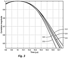
- Figure 3 shows the right hand side of each of a set of curves which are all centred around a particular moment in time (shown as 10.0 on the abscissa or x-axis which shows time in microseconds), corresponding to the drop in correlation value as two (identical) signals are moved further apart in time, for various signals 310, 330, 320, 340 and 350 which have different amounts of "transitioning" being high and low.
- the falloff of correlation steeper for some signals than others but the shape of the curve can also vary.
- FIG 4 shows an apparatus 400 for estimating a time-of-arrival of a packet received by a receiver (which may be, in the present context, either an initiator or a reflector).
- a receiver which may be, in the present context, either an initiator or a reflector.
- a plurality (or stream) of samples are received in a samples-buffer 410.
- the samples in the sample-buffer are FM demodulated samples, which are stored, for example, as 8-bit precision digital values.
- a bit-pattern detector which may be a relatively low-precision bit-pattern detector, 420 compares groups of samples to the reference bit-pattern and identifies a group of samples which matches the reference bit-pattern.
- This group of samples is further processed in a relatively high-precision correlator 430, to identify a set of three correlation values, comprising a local maximum correlation value, P0, 432, an immediately succeeding correlation value (or “plus 1"), Pp 434, and an immediately preceding (or “minus 1") correlation value Pm 436.
- the set of data comprising P0, Pm, Pp and the timing 438 of the packet detection, is post-processed in a postprocessor 440, using a function f( ⁇ ) of the difference, ⁇ , between Pm and Pp.
- the post-processing estimates, in an estimation unit, a timing offset T frac , between the local maximum correlation value P0, and a correlation peak using Pm and Pp, as will be described in more detail hereinbelow.
- the real and imaginary parts of the "exp (lj * ( ⁇ k-i - ref k ))" factors are 6-bit encoded for this low resolution correlator.
- bit-pattern detector Since the bit-pattern detector has relatively low precision (for instance, it might be 6-bit, as mention above), it does not require substantial computing power, and can be continuously operated.
- this information (in particular the value k max ) is transferred as shown at 425 to the relatively high precision correlator 430.
- the high precision correlator 130 then reuses the relevant group of samples, which as mentioned above may be 32 in number, from the sample buffer to find, with greater accuracy, the three correlation magnitudes, P0, Pm. and Pp, corresponding to values of k being k max , k max -1, and k max +1.
- the estimate of the position of the max (k max ) provided by the bit pattern detector may not have been correct.
- the increased accuracy provided by the high resolution correlator may result in the maximum correlation being for a different value of k.
- k max identified by the high precision correlator will be within +/-1 of that identified by the bit pattern detector.
- the correlator 430 provides accurate values for P0, Pm and Pp, and these are then used, along with the timing of the local maximum correlation value P0, to find the timing of the true peak of the correlation curve. This is illustrated in figure 5 .
- a simulated correlation magnitude 510 on the y-axis or coordinate is plotted against time, in ⁇ s, on the x-axis or abscissa.
- the correlation curve is symmetrical about a local true maximum tmax 520, which in this illustrative case is set at a notional time of 10 ⁇ s.
- a local maximum correlation value P0 is shown on the curve. In this illustrative example, P0 is close to the maximum, but offset in time by approximately 0.05 ⁇ s (that is to say, 50 ns).
- the bit rate is 1 MHz and this is sampling is at four times over-sampling, resulting in a sample being taken every 250 ns. So, also shown on the figure are 5 additional discrete time correlation sampling moments and the value of P resulting at each of these. Naturally they fall on the simulated continuous correlation curve 510. In particular the immediately preceding sample point Pm and immediately following sample point Pp are also shown.
- the value of k max identified by the low precision bit pattern detector 420 may not have been correct.
- the bit detector 420 identified the point 540 (shown in figure 5 is Pm) as being the local maximum.
- the high resolution correlator identifies that this original estimate is "off by one", and that the highest correlation value is found in the next sample.
- the timing of P0 provides a first estimate of the true moment of local maximum tmax; however, this moment may be adjusted, to determine the correct tmax using curve fitting.
- the values of Pm and Pm are used along with P0 to estimate tmax.
- tmax is earlier than - that is, to the left of - P0
- Pm is greater than Pp
- tmax is later than- that is, to the left of - P0.
- f( ⁇ ) may be approximated through a polynomial expansion.
- a proxy is used for the curve fitting.
- the correlation curve may be classified according to a parameter which we may define as its "bumpiness”: that is to say the frequency with which adjacent bits transition from high to low or vice versa.
- a bit-pattern with a high bumpiness would have many transitions across adjacent bits, and one with low bumpiness would have relatively few transitions - and thus extended sequences of "1s" or "0s".
- the inventors have appreciated that the bumpiness of the bit-pattern is directly related to the shape of the correlation curve: as a thought experiment only, consider a bit-pattern for which all the bits are the same (thus with zero bumpiness).
- the correlation would remain very high - and in the theoretical limit, for an infinite length bit-pattern the correlation would remain completely flat with a value 1. This is the limit for an extremely shallow correlation curve.
- the bit-pattern consists entirely of alternating ones "1s" "0s"
- the correlation would fall to 0 as the offset between the bit-pattern and its copy reaches one half-bit and would be completely anti-correlated (with a correlation magnitude back at 1) for an offset of a single bit - this is the limit for a steep fall-off of the correlation curve.
- cnt 010 , cnt 011 , cnt 111 relate to the bumpiness of the bit-pattern, and are defined as follows:
- Figure 6 shows an illustrative example of a 32-bit bit-pattern both in binary (“1s” and “0s”) form and in graphical ("high” and “low”) form.
- This particular bit-pattern has been chosen arbitrarily in order to illustrate the principle.
- the same bit-pattern is replicated, along with the ordinal number of each bit, along the top two rows of figure 7 .
- the bit-pattern has been extended with both a prior bit and a posterior bit, each of which have been assigned a preselected value ("1") in this instance.
- the lower three rows of the table in figure 7 show the contribution that each bit makes to the value of one, and only one, of the three components of C, that is cnt 010 , cnt 011 , or cnt 111 .
- C [14, 15, 3]
- the three values do not have to be calculated independently, but rather, only two need to be counted and the third can be computed from the above equation.
- Figure 8 illustrates performance simulations for a 32-bit bit-pattern, under a BLE round-trip time use case in which the bit rate is Gaussian FSK modulated having a 1 Mpbs transmission rate, modulation depth h of 0.5 and an impulse response with a BT of 0.5.
- the transformation matrix which depends both on the modulation parameters (BT and h), and on the response of the receiver front-end, has been pre-calculated.
- Bit-patterns were randomly generated and applied to a fixed-point implementation of the high accuracy correlator 430.
- "Fixed-point" here, applies both in terms of fixed-point data representation and fixed-point arithmetic computations. The skilled person will appreciate that such a fixed-point architecture introduces digital - quantisation - noise into the data.
- An analogue SNR of 25 dB was also introduced.
- the figure shows many individual (simulated) local maximum value correlations 810, 820, obtained in the following manner: a fractional delay (true ⁇ ) is imposed onto the received signal, with respect to the local sampling clock.
- the fractional delay is expressed in sample units (so the range is [-0.5*1 sample, +0.5*1 sample]). In the case of BLE-1Mbps the sampling period is 250 nanoseconds, so the fractional delay is a fraction of this value.
- the continuous line 830 represents the average of the "x" points for each imposed fractional delay, that is to say, an average distant measurement error, in dependence on the actual fractional delay.
- Figure 9 shows a cumulative distribution curve for instantaneous distance measurement error for the multiple simulations made and shown in figure 8 . It can be seen that a measurement accuracy of 109 cm of vector is achieved with a probability of 90%.
Applications Claiming Priority (1)
| Application Number | Priority Date | Filing Date | Title |
|---|---|---|---|
| RO202000576 | 2020-09-11 |
Publications (1)
| Publication Number | Publication Date |
|---|---|
| EP3968049A1 true EP3968049A1 (de) | 2022-03-16 |
Family
ID=75904797
Family Applications (1)
| Application Number | Title | Priority Date | Filing Date |
|---|---|---|---|
| EP21173225.0A Pending EP3968049A1 (de) | 2020-09-11 | 2021-05-11 | Verfahren und einrichtung zur schätzung einer ankunftszeit oder eines abstands zwischen zwei vorrichtungen |
Country Status (2)
| Country | Link |
|---|---|
| US (1) | US11621898B2 (de) |
| EP (1) | EP3968049A1 (de) |
Citations (4)
| Publication number | Priority date | Publication date | Assignee | Title |
|---|---|---|---|---|
| US20100317358A1 (en) * | 2009-06-16 | 2010-12-16 | Fujitsu Limited | Receiving apparatus, base station apparatus, and synchronization timing detection method |
| US7899085B2 (en) * | 2009-04-09 | 2011-03-01 | Itt Manufacturing Enterprises, Inc. | Ranging between radios using pseudo time of arrival sequence |
| US9635515B1 (en) * | 2015-06-22 | 2017-04-25 | Marvell International Ltd. | Apparatus and methods for generating an accurate estimate of a time of receipt of a packet |
| EP3315991A1 (de) * | 2016-10-28 | 2018-05-02 | Fraunhofer Gesellschaft zur Förderung der Angewand | Ankunftszeitmessungen |
Family Cites Families (8)
| Publication number | Priority date | Publication date | Assignee | Title |
|---|---|---|---|---|
| DE4318368C1 (de) * | 1993-05-28 | 1994-07-14 | Siemens Ag | Verfahren zum Gewinnen eines einen Ausfall der Synchronisation zwischen einer Pseudozufallssignalfolge eines Senders und einer Referenz-Pseudozufallssignalfolge eines Empfängers anzeigenden Signals |
| US6128331A (en) * | 1994-11-07 | 2000-10-03 | Cisco Systems, Inc. | Correlation system for use in wireless direct sequence spread spectrum systems |
| US7298806B1 (en) | 2004-01-15 | 2007-11-20 | Hellosoft Inc. | Method and system for data-aided timing offset estimation for frequency selective fading channels |
| US7492828B2 (en) | 2004-06-18 | 2009-02-17 | Qualcomm Incorporated | Time synchronization using spectral estimation in a communication system |
| US7916797B2 (en) | 2004-12-11 | 2011-03-29 | Electronics And Telecommunications Research Institute | Residual frequency, phase, timing offset and signal amplitude variation tracking apparatus and methods for OFDM systems |
| EP2405586B1 (de) | 2010-07-06 | 2018-08-22 | Keysight Technologies Singapore (Holdings) Pte.Ltd | Vorrichtung und Verfahren zur Piloterkennung |
| US9853787B2 (en) | 2015-06-24 | 2017-12-26 | Nxp Usa, Inc. | Carrier frequency offset estimation for wireless communication |
| US9729195B2 (en) | 2015-10-05 | 2017-08-08 | Nxp Usa, Inc. | Configurable correlator for joint timing and frequency synchronization and demodulation |
-
2021
- 2021-05-11 EP EP21173225.0A patent/EP3968049A1/de active Pending
- 2021-07-27 US US17/443,572 patent/US11621898B2/en active Active
Patent Citations (4)
| Publication number | Priority date | Publication date | Assignee | Title |
|---|---|---|---|---|
| US7899085B2 (en) * | 2009-04-09 | 2011-03-01 | Itt Manufacturing Enterprises, Inc. | Ranging between radios using pseudo time of arrival sequence |
| US20100317358A1 (en) * | 2009-06-16 | 2010-12-16 | Fujitsu Limited | Receiving apparatus, base station apparatus, and synchronization timing detection method |
| US9635515B1 (en) * | 2015-06-22 | 2017-04-25 | Marvell International Ltd. | Apparatus and methods for generating an accurate estimate of a time of receipt of a packet |
| EP3315991A1 (de) * | 2016-10-28 | 2018-05-02 | Fraunhofer Gesellschaft zur Förderung der Angewand | Ankunftszeitmessungen |
Also Published As
| Publication number | Publication date |
|---|---|
| US11621898B2 (en) | 2023-04-04 |
| US20220086068A1 (en) | 2022-03-17 |
Similar Documents
| Publication | Publication Date | Title |
|---|---|---|
| US10771288B2 (en) | Processing module for a communication device and method therefor | |
| JP4783481B1 (ja) | 超音波測定方法および超音波測定装置 | |
| EP1145084B1 (de) | Determination der zeitverzögerung und determination der signalverschiebung | |
| EP3321712A1 (de) | Verarbeitungsmodul und zugehöriges verfahren | |
| EP1913747B1 (de) | Algorithmus zur Fehlerschätzung schneller Trägerfrequenzen mittels Synchronisierungssequenzen | |
| WO2021003500A1 (en) | Interference suppression for multi-radar coexistence | |
| CN101902288B (zh) | 一种直序扩频二元相移键控调制器时延的测量方法 | |
| EP0933882B1 (de) | Schaltung zur Erkennung von Spitzenwerten eines zeitdiskreten Signals durch eine appoximierte Funktion | |
| CN101534159A (zh) | 一种用于td-scdma设备测试的矢量幅度误差测量方法和装置 | |
| CN102571676B (zh) | 正交频分复用系统中帧同步和频偏精确估计的方法 | |
| CN104735713A (zh) | 一种适应于宽带无线定位系统中的精确信号传播时延估计方法及实现装置 | |
| CN104641610A (zh) | 用于估计频率误差的方法和装置 | |
| RU2507536C1 (ru) | Обнаружитель-измеритель когерентно-импульсных сигналов | |
| EP3968049A1 (de) | Verfahren und einrichtung zur schätzung einer ankunftszeit oder eines abstands zwischen zwei vorrichtungen | |
| JP2010200319A (ja) | 特にモバイル装置の通信信号受信機の搬送波周波数シフトを推定するための方法 | |
| JP2009512869A (ja) | 相関及び微分相関の合成に基づく信号処理及び時間遅延測定 | |
| JP2001510566A (ja) | 所定の着信データ系列用の位相検出器 | |
| JP2009512868A (ja) | 物体検出 | |
| US7346098B2 (en) | Communication receiver | |
| CN115643139A (zh) | 一种抗频偏的突发信号检测系统及检测方法 | |
| EP1793546B1 (de) | Pilotdatengestützte Doppler-Frequenzschätzung | |
| KR100780195B1 (ko) | 펄스 신호의 오버랩 검출 장치, 방법 및 이를 포함하는거리 측정 장치 | |
| JP2009002943A (ja) | 測距システムおよび方法 | |
| RU2165627C1 (ru) | Доплеровский фазометр многочастотных сигналов | |
| US7630447B2 (en) | System of communication between synchronized submarine devices |
Legal Events
| Date | Code | Title | Description |
|---|---|---|---|
| PUAI | Public reference made under article 153(3) epc to a published international application that has entered the european phase |
Free format text: ORIGINAL CODE: 0009012 |
|
| STAA | Information on the status of an ep patent application or granted ep patent |
Free format text: STATUS: THE APPLICATION HAS BEEN PUBLISHED |
|
| AK | Designated contracting states |
Kind code of ref document: A1 Designated state(s): AL AT BE BG CH CY CZ DE DK EE ES FI FR GB GR HR HU IE IS IT LI LT LU LV MC MK MT NL NO PL PT RO RS SE SI SK SM TR |
|
| STAA | Information on the status of an ep patent application or granted ep patent |
Free format text: STATUS: REQUEST FOR EXAMINATION WAS MADE |
|
| 17P | Request for examination filed |
Effective date: 20220916 |
|
| RBV | Designated contracting states (corrected) |
Designated state(s): AL AT BE BG CH CY CZ DE DK EE ES FI FR GB GR HR HU IE IS IT LI LT LU LV MC MK MT NL NO PL PT RO RS SE SI SK SM TR |