EP3967647A1 - Station de remplissage de réservoirs de gaz - Google Patents
Station de remplissage de réservoirs de gaz Download PDFInfo
- Publication number
- EP3967647A1 EP3967647A1 EP21189276.5A EP21189276A EP3967647A1 EP 3967647 A1 EP3967647 A1 EP 3967647A1 EP 21189276 A EP21189276 A EP 21189276A EP 3967647 A1 EP3967647 A1 EP 3967647A1
- Authority
- EP
- European Patent Office
- Prior art keywords
- safety
- flexible portion
- circuit
- working axis
- wall
- Prior art date
- Legal status (The legal status is an assumption and is not a legal conclusion. Google has not performed a legal analysis and makes no representation as to the accuracy of the status listed.)
- Granted
Links
Images


Classifications
-
- F—MECHANICAL ENGINEERING; LIGHTING; HEATING; WEAPONS; BLASTING
- F17—STORING OR DISTRIBUTING GASES OR LIQUIDS
- F17C—VESSELS FOR CONTAINING OR STORING COMPRESSED, LIQUEFIED OR SOLIDIFIED GASES; FIXED-CAPACITY GAS-HOLDERS; FILLING VESSELS WITH, OR DISCHARGING FROM VESSELS, COMPRESSED, LIQUEFIED, OR SOLIDIFIED GASES
- F17C5/00—Methods or apparatus for filling containers with liquefied, solidified, or compressed gases under pressures
- F17C5/06—Methods or apparatus for filling containers with liquefied, solidified, or compressed gases under pressures for filling with compressed gases
-
- B—PERFORMING OPERATIONS; TRANSPORTING
- B67—OPENING, CLOSING OR CLEANING BOTTLES, JARS OR SIMILAR CONTAINERS; LIQUID HANDLING
- B67D—DISPENSING, DELIVERING OR TRANSFERRING LIQUIDS, NOT OTHERWISE PROVIDED FOR
- B67D7/00—Apparatus or devices for transferring liquids from bulk storage containers or reservoirs into vehicles or into portable containers, e.g. for retail sale purposes
- B67D7/06—Details or accessories
- B67D7/38—Arrangements of hoses, e.g. operative connection with pump motor
-
- F—MECHANICAL ENGINEERING; LIGHTING; HEATING; WEAPONS; BLASTING
- F17—STORING OR DISTRIBUTING GASES OR LIQUIDS
- F17C—VESSELS FOR CONTAINING OR STORING COMPRESSED, LIQUEFIED OR SOLIDIFIED GASES; FIXED-CAPACITY GAS-HOLDERS; FILLING VESSELS WITH, OR DISCHARGING FROM VESSELS, COMPRESSED, LIQUEFIED, OR SOLIDIFIED GASES
- F17C5/00—Methods or apparatus for filling containers with liquefied, solidified, or compressed gases under pressures
-
- B—PERFORMING OPERATIONS; TRANSPORTING
- B67—OPENING, CLOSING OR CLEANING BOTTLES, JARS OR SIMILAR CONTAINERS; LIQUID HANDLING
- B67D—DISPENSING, DELIVERING OR TRANSFERRING LIQUIDS, NOT OTHERWISE PROVIDED FOR
- B67D7/00—Apparatus or devices for transferring liquids from bulk storage containers or reservoirs into vehicles or into portable containers, e.g. for retail sale purposes
- B67D7/06—Details or accessories
- B67D7/32—Arrangements of safety or warning devices; Means for preventing unauthorised delivery of liquid
- B67D7/3218—Arrangements of safety or warning devices; Means for preventing unauthorised delivery of liquid relating to emergency shut-off means
-
- F—MECHANICAL ENGINEERING; LIGHTING; HEATING; WEAPONS; BLASTING
- F17—STORING OR DISTRIBUTING GASES OR LIQUIDS
- F17C—VESSELS FOR CONTAINING OR STORING COMPRESSED, LIQUEFIED OR SOLIDIFIED GASES; FIXED-CAPACITY GAS-HOLDERS; FILLING VESSELS WITH, OR DISCHARGING FROM VESSELS, COMPRESSED, LIQUEFIED, OR SOLIDIFIED GASES
- F17C13/00—Details of vessels or of the filling or discharging of vessels
- F17C13/12—Arrangements or mounting of devices for preventing or minimising the effect of explosion ; Other safety measures
-
- F—MECHANICAL ENGINEERING; LIGHTING; HEATING; WEAPONS; BLASTING
- F17—STORING OR DISTRIBUTING GASES OR LIQUIDS
- F17C—VESSELS FOR CONTAINING OR STORING COMPRESSED, LIQUEFIED OR SOLIDIFIED GASES; FIXED-CAPACITY GAS-HOLDERS; FILLING VESSELS WITH, OR DISCHARGING FROM VESSELS, COMPRESSED, LIQUEFIED, OR SOLIDIFIED GASES
- F17C5/00—Methods or apparatus for filling containers with liquefied, solidified, or compressed gases under pressures
- F17C5/002—Automated filling apparatus
- F17C5/007—Automated filling apparatus for individual gas tanks or containers, e.g. in vehicles
-
- F—MECHANICAL ENGINEERING; LIGHTING; HEATING; WEAPONS; BLASTING
- F17—STORING OR DISTRIBUTING GASES OR LIQUIDS
- F17C—VESSELS FOR CONTAINING OR STORING COMPRESSED, LIQUEFIED OR SOLIDIFIED GASES; FIXED-CAPACITY GAS-HOLDERS; FILLING VESSELS WITH, OR DISCHARGING FROM VESSELS, COMPRESSED, LIQUEFIED, OR SOLIDIFIED GASES
- F17C5/00—Methods or apparatus for filling containers with liquefied, solidified, or compressed gases under pressures
- F17C5/02—Methods or apparatus for filling containers with liquefied, solidified, or compressed gases under pressures for filling with liquefied gases
-
- B—PERFORMING OPERATIONS; TRANSPORTING
- B67—OPENING, CLOSING OR CLEANING BOTTLES, JARS OR SIMILAR CONTAINERS; LIQUID HANDLING
- B67D—DISPENSING, DELIVERING OR TRANSFERRING LIQUIDS, NOT OTHERWISE PROVIDED FOR
- B67D7/00—Apparatus or devices for transferring liquids from bulk storage containers or reservoirs into vehicles or into portable containers, e.g. for retail sale purposes
- B67D7/06—Details or accessories
- B67D7/84—Casings, cabinets or frameworks; Trolleys or like movable supports
-
- F—MECHANICAL ENGINEERING; LIGHTING; HEATING; WEAPONS; BLASTING
- F17—STORING OR DISTRIBUTING GASES OR LIQUIDS
- F17C—VESSELS FOR CONTAINING OR STORING COMPRESSED, LIQUEFIED OR SOLIDIFIED GASES; FIXED-CAPACITY GAS-HOLDERS; FILLING VESSELS WITH, OR DISCHARGING FROM VESSELS, COMPRESSED, LIQUEFIED, OR SOLIDIFIED GASES
- F17C2205/00—Vessel construction, in particular mounting arrangements, attachments or identifications means
- F17C2205/03—Fluid connections, filters, valves, closure means or other attachments
- F17C2205/0302—Fittings, valves, filters, or components in connection with the gas storage device
-
- F—MECHANICAL ENGINEERING; LIGHTING; HEATING; WEAPONS; BLASTING
- F17—STORING OR DISTRIBUTING GASES OR LIQUIDS
- F17C—VESSELS FOR CONTAINING OR STORING COMPRESSED, LIQUEFIED OR SOLIDIFIED GASES; FIXED-CAPACITY GAS-HOLDERS; FILLING VESSELS WITH, OR DISCHARGING FROM VESSELS, COMPRESSED, LIQUEFIED, OR SOLIDIFIED GASES
- F17C2205/00—Vessel construction, in particular mounting arrangements, attachments or identifications means
- F17C2205/03—Fluid connections, filters, valves, closure means or other attachments
- F17C2205/0302—Fittings, valves, filters, or components in connection with the gas storage device
- F17C2205/0352—Pipes
- F17C2205/0364—Pipes flexible or articulated, e.g. a hose
-
- F—MECHANICAL ENGINEERING; LIGHTING; HEATING; WEAPONS; BLASTING
- F17—STORING OR DISTRIBUTING GASES OR LIQUIDS
- F17C—VESSELS FOR CONTAINING OR STORING COMPRESSED, LIQUEFIED OR SOLIDIFIED GASES; FIXED-CAPACITY GAS-HOLDERS; FILLING VESSELS WITH, OR DISCHARGING FROM VESSELS, COMPRESSED, LIQUEFIED, OR SOLIDIFIED GASES
- F17C2205/00—Vessel construction, in particular mounting arrangements, attachments or identifications means
- F17C2205/03—Fluid connections, filters, valves, closure means or other attachments
- F17C2205/0302—Fittings, valves, filters, or components in connection with the gas storage device
- F17C2205/0376—Dispensing pistols
-
- F—MECHANICAL ENGINEERING; LIGHTING; HEATING; WEAPONS; BLASTING
- F17—STORING OR DISTRIBUTING GASES OR LIQUIDS
- F17C—VESSELS FOR CONTAINING OR STORING COMPRESSED, LIQUEFIED OR SOLIDIFIED GASES; FIXED-CAPACITY GAS-HOLDERS; FILLING VESSELS WITH, OR DISCHARGING FROM VESSELS, COMPRESSED, LIQUEFIED, OR SOLIDIFIED GASES
- F17C2221/00—Handled fluid, in particular type of fluid
- F17C2221/01—Pure fluids
- F17C2221/012—Hydrogen
-
- F—MECHANICAL ENGINEERING; LIGHTING; HEATING; WEAPONS; BLASTING
- F17—STORING OR DISTRIBUTING GASES OR LIQUIDS
- F17C—VESSELS FOR CONTAINING OR STORING COMPRESSED, LIQUEFIED OR SOLIDIFIED GASES; FIXED-CAPACITY GAS-HOLDERS; FILLING VESSELS WITH, OR DISCHARGING FROM VESSELS, COMPRESSED, LIQUEFIED, OR SOLIDIFIED GASES
- F17C2223/00—Handled fluid before transfer, i.e. state of fluid when stored in the vessel or before transfer from the vessel
- F17C2223/01—Handled fluid before transfer, i.e. state of fluid when stored in the vessel or before transfer from the vessel characterised by the phase
- F17C2223/0107—Single phase
- F17C2223/0123—Single phase gaseous, e.g. CNG, GNC
-
- F—MECHANICAL ENGINEERING; LIGHTING; HEATING; WEAPONS; BLASTING
- F17—STORING OR DISTRIBUTING GASES OR LIQUIDS
- F17C—VESSELS FOR CONTAINING OR STORING COMPRESSED, LIQUEFIED OR SOLIDIFIED GASES; FIXED-CAPACITY GAS-HOLDERS; FILLING VESSELS WITH, OR DISCHARGING FROM VESSELS, COMPRESSED, LIQUEFIED, OR SOLIDIFIED GASES
- F17C2223/00—Handled fluid before transfer, i.e. state of fluid when stored in the vessel or before transfer from the vessel
- F17C2223/01—Handled fluid before transfer, i.e. state of fluid when stored in the vessel or before transfer from the vessel characterised by the phase
- F17C2223/0146—Two-phase
- F17C2223/0153—Liquefied gas, e.g. LPG, GPL
- F17C2223/0161—Liquefied gas, e.g. LPG, GPL cryogenic, e.g. LNG, GNL, PLNG
-
- F—MECHANICAL ENGINEERING; LIGHTING; HEATING; WEAPONS; BLASTING
- F17—STORING OR DISTRIBUTING GASES OR LIQUIDS
- F17C—VESSELS FOR CONTAINING OR STORING COMPRESSED, LIQUEFIED OR SOLIDIFIED GASES; FIXED-CAPACITY GAS-HOLDERS; FILLING VESSELS WITH, OR DISCHARGING FROM VESSELS, COMPRESSED, LIQUEFIED, OR SOLIDIFIED GASES
- F17C2223/00—Handled fluid before transfer, i.e. state of fluid when stored in the vessel or before transfer from the vessel
- F17C2223/03—Handled fluid before transfer, i.e. state of fluid when stored in the vessel or before transfer from the vessel characterised by the pressure level
- F17C2223/033—Small pressure, e.g. for liquefied gas
-
- F—MECHANICAL ENGINEERING; LIGHTING; HEATING; WEAPONS; BLASTING
- F17—STORING OR DISTRIBUTING GASES OR LIQUIDS
- F17C—VESSELS FOR CONTAINING OR STORING COMPRESSED, LIQUEFIED OR SOLIDIFIED GASES; FIXED-CAPACITY GAS-HOLDERS; FILLING VESSELS WITH, OR DISCHARGING FROM VESSELS, COMPRESSED, LIQUEFIED, OR SOLIDIFIED GASES
- F17C2223/00—Handled fluid before transfer, i.e. state of fluid when stored in the vessel or before transfer from the vessel
- F17C2223/03—Handled fluid before transfer, i.e. state of fluid when stored in the vessel or before transfer from the vessel characterised by the pressure level
- F17C2223/036—Very high pressure (>80 bar)
-
- F—MECHANICAL ENGINEERING; LIGHTING; HEATING; WEAPONS; BLASTING
- F17—STORING OR DISTRIBUTING GASES OR LIQUIDS
- F17C—VESSELS FOR CONTAINING OR STORING COMPRESSED, LIQUEFIED OR SOLIDIFIED GASES; FIXED-CAPACITY GAS-HOLDERS; FILLING VESSELS WITH, OR DISCHARGING FROM VESSELS, COMPRESSED, LIQUEFIED, OR SOLIDIFIED GASES
- F17C2260/00—Purposes of gas storage and gas handling
- F17C2260/03—Dealing with losses
- F17C2260/035—Dealing with losses of fluid
-
- F—MECHANICAL ENGINEERING; LIGHTING; HEATING; WEAPONS; BLASTING
- F17—STORING OR DISTRIBUTING GASES OR LIQUIDS
- F17C—VESSELS FOR CONTAINING OR STORING COMPRESSED, LIQUEFIED OR SOLIDIFIED GASES; FIXED-CAPACITY GAS-HOLDERS; FILLING VESSELS WITH, OR DISCHARGING FROM VESSELS, COMPRESSED, LIQUEFIED, OR SOLIDIFIED GASES
- F17C2265/00—Effects achieved by gas storage or gas handling
- F17C2265/06—Fluid distribution
- F17C2265/061—Fluid distribution for supply of supplying vehicles
-
- F—MECHANICAL ENGINEERING; LIGHTING; HEATING; WEAPONS; BLASTING
- F17—STORING OR DISTRIBUTING GASES OR LIQUIDS
- F17C—VESSELS FOR CONTAINING OR STORING COMPRESSED, LIQUEFIED OR SOLIDIFIED GASES; FIXED-CAPACITY GAS-HOLDERS; FILLING VESSELS WITH, OR DISCHARGING FROM VESSELS, COMPRESSED, LIQUEFIED, OR SOLIDIFIED GASES
- F17C2265/00—Effects achieved by gas storage or gas handling
- F17C2265/06—Fluid distribution
- F17C2265/065—Fluid distribution for refuelling vehicle fuel tanks
-
- F—MECHANICAL ENGINEERING; LIGHTING; HEATING; WEAPONS; BLASTING
- F17—STORING OR DISTRIBUTING GASES OR LIQUIDS
- F17C—VESSELS FOR CONTAINING OR STORING COMPRESSED, LIQUEFIED OR SOLIDIFIED GASES; FIXED-CAPACITY GAS-HOLDERS; FILLING VESSELS WITH, OR DISCHARGING FROM VESSELS, COMPRESSED, LIQUEFIED, OR SOLIDIFIED GASES
- F17C2270/00—Applications
- F17C2270/01—Applications for fluid transport or storage
- F17C2270/0134—Applications for fluid transport or storage placed above the ground
- F17C2270/0139—Fuel stations
-
- F—MECHANICAL ENGINEERING; LIGHTING; HEATING; WEAPONS; BLASTING
- F17—STORING OR DISTRIBUTING GASES OR LIQUIDS
- F17C—VESSELS FOR CONTAINING OR STORING COMPRESSED, LIQUEFIED OR SOLIDIFIED GASES; FIXED-CAPACITY GAS-HOLDERS; FILLING VESSELS WITH, OR DISCHARGING FROM VESSELS, COMPRESSED, LIQUEFIED, OR SOLIDIFIED GASES
- F17C2270/00—Applications
- F17C2270/01—Applications for fluid transport or storage
- F17C2270/0165—Applications for fluid transport or storage on the road
- F17C2270/0168—Applications for fluid transport or storage on the road by vehicles
-
- Y—GENERAL TAGGING OF NEW TECHNOLOGICAL DEVELOPMENTS; GENERAL TAGGING OF CROSS-SECTIONAL TECHNOLOGIES SPANNING OVER SEVERAL SECTIONS OF THE IPC; TECHNICAL SUBJECTS COVERED BY FORMER USPC CROSS-REFERENCE ART COLLECTIONS [XRACs] AND DIGESTS
- Y02—TECHNOLOGIES OR APPLICATIONS FOR MITIGATION OR ADAPTATION AGAINST CLIMATE CHANGE
- Y02E—REDUCTION OF GREENHOUSE GAS [GHG] EMISSIONS, RELATED TO ENERGY GENERATION, TRANSMISSION OR DISTRIBUTION
- Y02E60/00—Enabling technologies; Technologies with a potential or indirect contribution to GHG emissions mitigation
- Y02E60/30—Hydrogen technology
- Y02E60/32—Hydrogen storage
Definitions
- the invention relates to a filling station for gas tanks.
- the invention relates more particularly to a gas tank filling station comprising a gas source, a circuit comprising an upstream end connected to the source and a downstream end comprising a flexible portion whose termination is intended to be connected to the tank(s). ) to be filled, the circuit comprising between the source and the downstream end, an automatic closing safety coupling arranged along a working axis, said safety coupling ensuring automatic closing of the circuit in the event of determined traction of said safety coupling according to its working axis, the station comprising a distribution casing, the safety coupling being arranged in the distribution casing with a determined orientation of the working axis, at least part of the flexible portion of the downstream end of the circuit forming projecting out of the timing case, the timing case comprising a member for guiding a zone of the flexible portion.
- the terminal nozzle When filling the gaseous (or liquid) hydrogen tank of a vehicle, the terminal nozzle (or nozzle) is connected to the vehicle. It is up to the user to remember to disconnect the gun at the end of filling. If he forgets and leaves with his vehicle with the gun connected, tearing of the hose and damage to the distributor is possible.
- Known systems require the tensile force exerted to be in the working axis of the safety coupling system (or with a small angle, that is to say between zero and thirty degrees).
- the safety coupling is integrated into the gun.
- the safety coupling is generally fixed in a vertical position at a height of 2-3 meters from the ground with a connection of the hose downwards.
- a large angle with respect to the vertical is possible and therefore a large angle with respect to the axis of the safety coupling. This angle is generally greater than 45 degrees. This is outside the optimal operating conditions of the uncoupling system and malfunctions could occur leading to a dangerous situation.
- the safety coupling is arranged in line between two hoses: the hose which connects it to the distributor and the hose which connects it to the vehicle.
- This system has the advantage of being in the axis when the hose is under tension and therefore the tearing system works correctly.
- the hose connecting the safety coupling to the distributor is always in motion when the user handles the gun. This leads to wear of a second hose.
- An object of the present invention is to overcome all or part of the drawbacks of the prior art noted above.
- the station according to the invention is essentially characterized in that the guide member comprises a set of deflecting wall(s) ) converging(s) towards a central passage zone ensuring the localized maintenance of the flexible portion, the portion of the circuit located between the safety coupling and the guide member being oriented at least approximately along the working axis of the coupling of security, the set of deflecting wall(s) of the guide member being configured to also ensure a transfer, along the working axis of the safety coupling, of at least part of the tensile forces on the flexible portion oriented transversely to the working axis of the safety coupling.
- the invention may also relate to any alternative device or method comprising any combination of the characteristics above or below within the scope of the claims.
- the illustrated gas tank filling station 1 comprises a source 2 of gas, a circuit 3 comprising an upstream end 4 connected to the source 2 and a downstream end 5 comprising a flexible portion whose termination is intended to be connected to the ) reservoir(s) 6 to be filled (for example via a nozzle or a gun).
- Circuit 3 further comprises, between source 2 and downstream end 5, a self-closing safety connector 7 mounted along a line of work.
- This safety connector 7 is configured to ensure automatic closing of the circuit 3 (and a separation of the circuit into two parts if necessary) in the event of determined traction of said safety connector 7 along its working axis.
- the station 1 comprises a casing 8 of distribution, the connector 7 of security being arranged (fixed for example) in the casing 8 of distribution with a determined orientation of the axis of work, for example horizontal in the example represented.
- the casing 8 of distribution comprises a member 9 for guiding a zone of the flexible portion.
- the guide member 9 comprises a set of deflecting wall(s) 10 converging towards a central passage zone of the flexible hose and ensuring the localized maintenance of the flexible portion.
- the guide member 9 maintains the portion of the circuit 3 located between the safety connector 7 and the guide member 9 at least substantially along the working axis of the safety connector 7 (that is to say substantially horizontal in this embodiment, the term "substantially” meaning for example that a slight angle of zero to thirty degrees and preferably zero to ten degrees with respect to the working axis may be possible).
- the assembly of wall(s) 10 deflecting(s) of the guide member 9 is further configured to ensure a transfer, along the working axis of the safety connector 7, of at least part of the forces of traction exerted on the flexible portion oriented transversely relative to the working axis of the connector 7 of security. That is to say that, in the event of traction on the downstream end of the circuit (vehicle which leaves without disconnecting), even if the hose makes a significant angle A with the working axis of the safety connector 7, the guide member 9 forms a deflection system, preferably multidirectional, which transfers the efforts in the working axis of the connection 7 of safety and in particular allows the hose to escape the corners of the housing 8 distributor.
- the flexible portion rests solely on the set of wall(s) of the guide member 9 regardless of the orientation of the downstream part of the flexible portion.
- the guide member 9 may project relative to the face of the distributor housing 8 on which the guide member 9 opens.
- Station 1 security is improved. Indeed, when the vehicle goes forwards or backwards, the deflection system makes it possible to retransmit the forces in the working axis of the connection 7 of safety. Station 1 is also more flexible, as the system allows two-way vehicle access, which is not currently possible safely on existing installations.
- the assembly of deflecting wall(s) 10 comprises one or more curved walls having a radius of curvature of between 5 mm and 300 mm, for example (without this range being limiting).
- the assembly of deflecting wall(s) 10 forms a convergent tube or part of a tube (radius of curvature which decreases towards the upstream end).
- the set of wall(s) 10 deflecting(s) can comprise a torus section (or an entire torus).
- the set of deflecting wall(s) 10 comprises for example at least one fixed wall.
- the set of deflector wall(s) may comprise at least one movable wall, for example a roller mounted on an axis (movable or fixed) and in rotation about this axis.
- the guide member 9 may comprise two lateral deflecting wall(s) 10 oriented vertically and forming lateral abutments on either side of the flexible portion, the two side walls 10 can each be formed by a roller rotating around a vertical axis.
- the assembly of deflecting wall(s) may comprise an upper wall oriented horizontally (in particular a roller rotating around a horizontal axis) and forming a vertical abutment above the flexible portion and/or a lower wall oriented horizontally (in particular a roller rotating around a horizontal axis) and forming a vertical stop below the flexible portion.
- This configuration makes it possible to transfer to the working axis of the safety coupling 7 both the horizontal pulls of the hose on the two opposite sides and the pulls on the hose upwards or downwards. This allows the transfer of the vertical and horizontal components of the tensile forces.
- the working axis of the safety connector 7 is not necessarily horizontal.
- this safety connector 7 and the guide member 9 could be arranged at any height.
- this safety connector 7 and the guide member 9 are fixed at the usual height of connection of the terminal end of the hose to the tanks (at the average height of the inlet/outlet of the tank, for example around 'one meter).
- the walls 10 or horizontal rollers carrying the vertical components of the forces are optional.
- the guidance system can therefore be further simplified.
- the height of the system in relation to the average height of the tanks can vary by several tens of centimeters without compromising operation.
- the maximum angle of inclination of the hose at the outlet of the deflection system thus remaining lower than the value recommended by the manufacturer of the safety connector 7 and within the useful height of the guide member 9.
- the invention allows a reduction in the number of parts required (a single guide/deflection direction if necessary or, in the case of the torus, a single guide element). Such a structure therefore allows a simplification of the structure and of the assembly as well as an improvement in the efficiency of the security system while being less expensive.
- the guide member 9 comprises a torus or half-torus, this gives flexibility on the shape of the distributor housing 8 and the location of the safety connector 7 and guide member 9 assembly.
Landscapes
- Engineering & Computer Science (AREA)
- Mechanical Engineering (AREA)
- General Engineering & Computer Science (AREA)
- Filling Or Discharging Of Gas Storage Vessels (AREA)
- Loading And Unloading Of Fuel Tanks Or Ships (AREA)
Abstract
Description
- L'invention concerne une station de remplissage de réservoirs de gaz.
- L'invention concerne plus particulièrement une station de remplissage de réservoirs de gaz comprenant une source de gaz, un circuit comprenant une extrémité amont reliée à la source et une extrémité aval comprenant une portion flexible dont la terminaison est destinée à être raccordée au réservoir(s) à remplir, le circuit comprenant entre la source et l'extrémité aval, un raccord de sécurité à fermeture automatique agencé selon un axe de travail, ledit raccord de sécurité assurant une fermeture automatique du circuit en cas de traction déterminée dudit raccord de sécurité selon son axe de travail, la station comprenant un carter de distribution, le raccord de sécurité étant disposé dans le carter de distribution avec orientation déterminée de l'axe de travail, au moins une partie de la portion flexible de l'extrémité aval du circuit faisant saillie hors du carter de distribution, le carter de distribution comprenant un organe de guidage d'une zone de la portion flexible.
- Lors d'un remplissage du réservoir d'hydrogène gazeux (ou liquide) d'un véhicule, le pistolet (ou buse) terminal est raccordé au véhicule. C'est à l'utilisateur de penser à déconnecter le pistolet en fin de remplissage. S'il oublie et repart avec son véhicule avec le pistolet raccordé, l'arrachement du flexible et l'endommagement du distributeur est possible.
- Afin d'éviter des dommages au flexible et au distributeur, un système de désaccouplement est nécessaire. De nombreux systèmes existent utilisant des raccords de sécurité (« breakaway » en anglais) qui assurent la fermeture du circuit en cas de démarrage de la voiture alors que le pistolet est toujours connecté. La déconnexion est alors automatique, que le système soit sous pression ou non. Les raccords de sécurité sont réutilisables et peuvent être reconnectés en toute sécurité.
- Les système connus imposent que l'effort de traction exercé soit dans l'axe de travail du système du raccord de sécurité (ou avec un angle faible c'est-à-dire compris entre zéro et trente degrés). Dans des systèmes de sécurité connus, le raccord de sécurité est intégré au pistolet.
- Selon une autre configuration connue dite de « montage fixe », le raccord de sécurité est fixé en général en position verticale à une hauteur de 2-3 mètres du sol avec une connexion du flexible vers le bas. Cependant, lors de l'arrachement, un angle important par rapport à la verticale est possible et donc un angle important par rapport à l'axe du raccord de sécurité. Cet angle est en général supérieur à 45 degrés. Cela est en dehors des conditions de fonctionnement optimales du système de désaccouplement et des dysfonctionnements pourraient apparaître entraînant une situation dangereuse.
- Dans une autre configuration connue, le raccord de sécurité est disposé en ligne entre deux flexibles: le flexible qui le relie au distributeur et le flexible qui le relie au véhicule. Ce système a l'avantage de se mettre dans l'axe lorsque le flexible est mis sous tension et donc le système d'arrachement fonctionne correctement. Néanmoins, le flexible reliant le raccord de sécurité au distributeur est toujours en mouvement lorsque l'utilisateur manipule le pistolet. Cela entraine une usure d'un deuxième flexible.
- Un but de la présente invention est de pallier tout ou partie des inconvénients de l'art antérieur relevés ci-dessus.
- A cette fin, la station selon l'invention, par ailleurs conforme à la définition générique qu'en donne le préambule ci-dessus, est essentiellement caractérisé en ce que l'organe de guidage comprend un ensemble de paroi(s) déflectrice(s) convergentes(s) vers une zone centrale de passage assurant le maintien localisé de la portion flexible, la portion du circuit située entre le raccord de sécurité et l'organe de guidage étant orientée au moins sensiblement selon l'axe de travail du raccord de sécurité, l'ensemble de paroi(s) déflectrice(s) de l'organe de guidage étant configurés pour assurer en outre un report, selon l'axe de travail du raccord de sécurité, d'au moins un partie des efforts de traction sur la portion flexible orientés transversalement par rapport à l'axe de travail du raccord de sécurité.
- Ceci permet de disposer d'un raccord de sécurité qui peut être logé de façon rigide et fixe dans un distributeur de station 1. De plus, l'arrachement éventuel du flexible est ainsi réalisé tout le temps dans l'axe de travail du raccord de sécurité, quel que soit le sens du départ d'un véhicule (vers l'avant et l'arrière) qui partirait sans se déconnecter et quel que soit le côté du remplissage (gauche ou droite) d'un véhicule.
- Par ailleurs, des modes de réalisation de l'invention peuvent comporter l'une ou plusieurs des caractéristiques suivantes :
- l'ensemble de paroi(s) déflectrice(s) comprend une ou des parois courbes ayant un rayon de courbure compris entre 5mm et 300mm,
- l'ensemble de paroi(s) déflectrice(s) comprend au moins une paroi fixe,
- l'ensemble de paroi(s) déflectrice(s) comprend au moins une paroi mobile, notamment un rouleau monté sur un axe mobile en rotation sur lui-même,
- l'ensemble de paroi(s) déflectrice(s) comprend au moins deux parois latérales orientée verticalement et formant des butées latérales de part et d'autre de la portion flexible,
- l'ensemble de paroi(s) déflectrice(s) comprend au moins l'un parmi : une paroi supérieure orientée horizontalement et formant une butée verticale au-dessus de la portion flexible, une paroi inférieure orientée horizontalement et formant une butée verticale en-dessous de la portion flexible,
- le raccord de sécurité est disposé dans le carter avec orientation parallèle ou sensiblement parallèle à l'axe de travail,
- le raccord de sécurité est disposé dans le carter à une hauteur comprise entre 5cm et 3m et de préférence entre 50cm et 1m par rapport au sol,
- la source de gaz contient un gaz carburant comprenant ou constitué d'hydrogène sous forme liquide et/ou sous forme gazeuse.
- L'invention peut concerner également tout dispositif ou procédé alternatif comprenant toute combinaison des caractéristiques ci-dessus ou ci-dessous dans le cadre des revendications.
- D'autres particularités et avantages apparaîtront à la lecture de la description ci-après, faite en référence aux figures dans lesquelles :
- [
Fig. 1 ] représente une vue de côté, schématique et partielle, illustrant un exemple de structure de station selon l'invention, - [
Fig. 2 ] représente une vue en coupe verticale, schématique et partielle, illustrant un exemple de réalisation d'un détail de la station selon l'invention, - [
Fig. 3 ] représente une vue en perspective, schématique et partielle, illustrant un exemple de réalisation d'un détail d'un organe de guidage de la [Fig. 2 ], - [
Fig. 4 ] représente une vue en perspective, schématique et partielle, illustrant un exemple de structure de station selon l'invention, - [
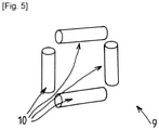
Fig. 5 ] représente une vue en perspective, schématique et partielle, illustrant un autre exemple de réalisation d'une partie d'une station selon l'invention. - La station 1 de remplissage de réservoirs de gaz illustrée comprend une source 2 de gaz, un circuit 3 comprenant une extrémité amont 4 reliée à la source 2 et une extrémité aval 5 comprenant une portion flexible dont la terminaison est destinée à être raccordée au(x) réservoir(s) 6 à remplir (par exemple via une buse ou un pistolet).
- Le circuit 3 comprend en outre, entre la source 2 et l'extrémité aval 5, un raccord 7 de sécurité à fermeture automatique monté selon un axe de travail. Ce raccord 7 de sécurité est configuré pour assurer une fermeture automatique du circuit 3 (et une séparation du circuit en deux parties le cas échéant) en cas de traction déterminée dudit raccord 7 de sécurité selon son axe de travail.
- La station 1 comprend un carter 8 de distribution, le raccord 7 de sécurité étant disposé (fixé par exemple) dans le carter 8 de distribution avec une orientation déterminée de l'axe de travail par exemple horizontale dans l'exemple représenté.
- Au moins une partie de la portion flexible de l'extrémité 5 aval du circuit fait saillie hors du carter 8 de distribution. De plus, le carter 8 de distribution comprend un organe 9 de guidage d'une zone de la portion flexible.
- L'organe 9 de guidage comprend un ensemble de paroi(s) 10 déflectrice(s) convergente(s) vers une zone centrale de passage du flexible et assurant le maintien localisé de la portion flexible. L'organe 9 de guidage maintient la portion du circuit 3 située entre le raccord 7 de sécurité et l'organe 9 de guidage au moins sensiblement selon l'axe de travail du raccord 7 de sécurité (c'est-dire sensiblement horizontale dans cet exemple de réalisation, le terme « sensiblement » signifiant par exemple qu'un léger angle de zéro à trente degrés et de préférence de zéro à dix degrés par rapport à l'axe de travail peut être possible).
- L'ensemble de paroi(s) 10 déflectrice(s) de l'organe 9 de guidage est en outre configuré pour assurer un report, selon l'axe de travail du raccord 7 de sécurité, d'au moins une partie des efforts de traction exercés sur la portion flexible orientés transversalement par rapport à l'axe de travail du raccord 7 de sécurité. C'est-à-dire que, en cas de traction sur l'extrémité aval du circuit (véhicule qui part sans se déconnecter), même si le flexible fait un angle A important avec l'axe de travail du raccord 7 de sécurité, l'organe 9 de guidage forme un système de déflexion, de préférence multidirectionnel, qui reporte les efforts dans l'axe de travail du raccord 7 de sécurité et notamment permet au flexible d'échapper les angles du carter 8 distributeur. C'est-à-dire que, de préférence, la portion flexible repose uniquement sur l'ensemble de paroi(s) de l'organe 9 de guidage quelle que soit l'orientation de la partie aval de la portion flexible. Par exemple, l'organe 9 de guidage peut faire saillie par rapport à la face du carter 8 distributeur sur laquelle l'organe 9 de guidage débouche.
- La sécurité de la station 1 est améliorée. En effet, lorsque le véhicule part vers l'avant ou vers l'arrière, le système de déflexion permet de retransmettre les efforts dans l'axe de travail du raccord 7 de sécurité. La station 1 est également plus flexible, car le système permet un accès aux véhicules dans les deux sens, ce qui n'est aujourd'hui pas possible en toute sécurité sur les installations existantes.
- Par exemple, l'ensemble de paroi(s) 10 déflectrice(s) comprend une ou des parois courbes ayant un rayon de courbure compris entre 5mm et 300mm_par exemple (sans que cette gamme soit limitative). Par exemple, l'ensemble de paroi(s) 10 déflectrice(s) forme un tube ou une partie de tube convergent (rayon de courbure qui diminue vers l'extrémité amont).
- Comme illustré aux [
Fig. 2 ] et [Fig. 3 ], l'ensemble de paroi(s) 10 déflectrice(s) peut comporter une section de tore (ou un tore entier). - L'ensemble de paroi(s) 10 déflectrices comprend par exemple au moins une paroi fixe.
- Alternativement ou en combinaison l'ensemble de paroi(s) 10 déflectrice(s) peut comprendre au moins une paroi mobile par exemple un rouleau monté sur un axe (mobile ou fixe) et en rotation autour de cet axe. Comme illustré à la [
Fig. 4 ], l'organe 9 de guidage peut comprendre deux paroi(s) 10 déflectrices latérales orientées verticalement et formant des butées latérales de part et d'autre de la portion flexible, les deux parois 10 latérales peuvent être formées chacune par un rouleau rotatif autour d'un axe vertical. - Comme illustré à la [
Fig. 5 ], l'ensemble de paroi(s) 10 déflectrice(s) peut comprendre une paroi supérieure orientée horizontalement (notamment un rouleau rotatif autour d'un axe horizontal) et formant une butée verticale au-dessus de la portion flexible et/ou une paroi inférieure orientée horizontalement (notamment un rouleau rotatif autour d'un axe horizontal) et formant une butée verticale en-dessous de la portion flexible. - Cette configuration permet de reporter dans l'axe de travail du raccord 7 de sécurité aussi bien les tractions horizontales du flexible des deux côtés opposés que les tractions sur le flexible vers le haut ou vers le bas. Ceci permet le report des composantes verticales et horizontales des efforts de traction. Bien entendu, l'axe de travail du raccord 7 de sécurité n'est pas nécessairement horizontal.
- De plus, ce raccord 7 de sécurité et l'organe 9 de guidage pourrait être disposés à une hauteur quelconque.
- De préférence, ce raccord 7 de sécurité et l'organe 9 de guidage sont fixés à la hauteur usuelle de raccordement de l'extrémité terminale du flexible aux réservoirs (à la hauteur moyenne de l'entrée/sortie du réservoir, par exemple autour d'un mètre).
- Dans le cas où le raccord 7 de sécurité est fixé à la hauteur de l'entrée du réservoir à remplir, les parois 10 ou rouleaux horizontaux reportant les composantes verticales des efforts sont facultatifs. Le système de guidage peut donc être encore simplifié.
- La longueur du flexible étant généralement de plusieurs mètres, la hauteur du système par rapport à la hauteur moyenne des réservoirs peut varier de plusieurs dizaines de centimètres sans compromettre le fonctionnement. L'angle maximale d'inclinaison du flexible en sortie du système de déflexion restant ainsi inférieur à la valeur préconisée par le fabricant du raccord 7 de sécurité et dans la hauteur utile de l'organe 9 de guidage.
- L'invention permet une réduction du nombre de pièces nécessaires (une seule direction de guidage/déflexion si besoin ou, dans le cas du tore, un seul élément de guidage). Une telle structure permet donc une simplification de la structure et de l'assemblage ainsi qu'une amélioration de l'efficacité du système de sécurité tout en étant moins coûteux.
- Dans le cas notamment où l'organe 9 de guidage comprend un tore ou demi-tore, cela donne une flexibilité sur la forme du carter 8 distributeur et l'emplacement de l'ensemble raccord 7 de sécurité et organe 9 de guidage.
Claims (9)
- Station de remplissage de réservoirs de gaz comprenant une source (2) de gaz, un circuit (3) comprenant une extrémité amont (4) reliée à la source (2) et une extrémité aval (5) comprenant une portion flexible dont la terminaison est destinée à être raccordée au réservoir(s) (6) à remplir, le circuit (3) comprenant entre la source (2) et l'extrémité aval (5), un raccord (7) de sécurité à fermeture automatique agencé selon un axe de travail, ledit raccord (7) de sécurité assurant une fermeture automatique du circuit (3) en cas de traction déterminée dudit raccord (7) de sécurité selon son axe de travail, la station (1) comprenant un carter (8) de distribution, le raccord (7) de sécurité étant disposé dans le carter (8) de distribution avec orientation déterminée de l'axe de travail, au moins une partie de la portion flexible de l'extrémité (5) aval du circuit faisant saillie hors du carter (8) de distribution, le carter (8) de distribution comprenant un organe (9) de guidage d'une zone de la portion flexible, caractérisée en ce que l'organe (9) de guidage comprend un ensemble de paroi(s) (10) déflectrice(s) convergentes(s) vers une zone centrale de passage assurant le maintien localisé de la portion flexible, la portion du circuit (3) située entre le raccord (7) de sécurité et l'organe (9) de guidage étant orientée au moins sensiblement selon l'axe de travail du raccord (7) de sécurité, l'ensemble de paroi(s) (10) déflectrice(s) de l'organe (9) de guidage étant configurés pour assurer en outre un report, selon l'axe de travail du raccord (7) de sécurité, d'au moins un partie des efforts de traction sur la portion flexible orientés transversalement par rapport à l'axe de travail du raccord (7) de sécurité.
- Station selon la revendication 1, caractérisée en ce que l'ensemble de paroi(s) (10) déflectrice(s) comprend une ou des parois courbes ayant un rayon de courbure compris entre 5mm et 300mm.
- Station selon la revendication 1 ou 2, caractérisée en ce que l'ensemble de paroi(s) (10) déflectrice(s) comprend au moins une paroi fixe.
- Station selon l'une quelconque des revendications 1 à 3, caractérisée en ce que l'ensemble de paroi(s) (10) déflectrice(s) comprend au moins une paroi mobile, notamment un rouleau monté sur un axe mobile en rotation sur lui-même.
- Station selon l'une quelconque des revendications 1 à 4, caractérisée en ce que l'ensemble de paroi(s) (10) déflectrice(s) comprend au moins deux parois latérales orientée verticalement et formant des butées latérales de part et d'autre de la portion flexible.
- Station selon l'une quelconque des revendications 1 à 5, caractérisée en ce que l'ensemble de paroi(s) (10) déflectrice(s) comprend au moins l'un parmi : une paroi supérieure orientée horizontalement et formant une butée verticale au-dessus de la portion flexible, une paroi inférieure orientée horizontalement et formant une butée verticale en-dessous de la portion flexible.
- Station selon l'une quelconque des revendications 1 à 6, caractérisée en ce que le raccord (7) de sécurité est disposé dans le carter (8) avec orientation parallèle ou sensiblement parallèle à l'axe de travail.
- Station selon l'une quelconque des revendications 1 à 7, caractérisée en ce que le raccord (7) de sécurité est disposé dans le carter (8) à une hauteur comprise entre 5cm et 3m et de préférence entre 50cm et 1m par rapport au sol.
- Station selon l'une quelconque des revendications 1 à 8, caractérisée en ce que la source (2) de gaz contient un gaz carburant comprenant ou constitué d'hydrogène sous forme liquide et/ou sous forme gazeuse.
Applications Claiming Priority (1)
| Application Number | Priority Date | Filing Date | Title |
|---|---|---|---|
| FR2009149A FR3113900B1 (fr) | 2020-09-10 | 2020-09-10 | Station de remplissage de réservoirs de gaz |
Publications (2)
| Publication Number | Publication Date |
|---|---|
| EP3967647A1 true EP3967647A1 (fr) | 2022-03-16 |
| EP3967647B1 EP3967647B1 (fr) | 2023-07-19 |
Family
ID=73497963
Family Applications (1)
| Application Number | Title | Priority Date | Filing Date |
|---|---|---|---|
| EP21189276.5A Active EP3967647B1 (fr) | 2020-09-10 | 2021-08-03 | Station de remplissage de réservoirs de gaz |
Country Status (7)
| Country | Link |
|---|---|
| US (1) | US20220074551A1 (fr) |
| EP (1) | EP3967647B1 (fr) |
| JP (1) | JP7731742B2 (fr) |
| KR (1) | KR20220034000A (fr) |
| CN (1) | CN114165724B (fr) |
| DK (1) | DK3967647T3 (fr) |
| FR (1) | FR3113900B1 (fr) |
Families Citing this family (4)
| Publication number | Priority date | Publication date | Assignee | Title |
|---|---|---|---|---|
| JP7459896B2 (ja) | 2022-05-31 | 2024-04-02 | 株式会社タツノ | 安全継手用収容装置 |
| JP7526392B2 (ja) * | 2022-06-14 | 2024-08-01 | 株式会社タツノ | 安全継手用収容装置 |
| JP7544104B2 (ja) * | 2022-09-05 | 2024-09-03 | 株式会社タツノ | 充填ホース案内装置 |
| JP7571772B2 (ja) * | 2022-09-21 | 2024-10-23 | 株式会社タツノ | 安全継手用収容装置 |
Citations (4)
| Publication number | Priority date | Publication date | Assignee | Title |
|---|---|---|---|---|
| US2225271A (en) * | 1939-05-12 | 1940-12-17 | Gilber & Barker Mfg Company | Fluid dispensing apparatus |
| US2776093A (en) * | 1953-07-20 | 1957-01-01 | James H Cox | Hose retriever |
| BE554752A (fr) * | 1957-02-05 | 1957-02-28 | Installation a enrouleur automatique de tuyau pour garages et stations de graissage | |
| WO2000061490A1 (fr) * | 1999-04-14 | 2000-10-19 | Dresser, Inc. | Dispositif et procede de manipulation d'un tube flexible |
Family Cites Families (9)
| Publication number | Priority date | Publication date | Assignee | Title |
|---|---|---|---|---|
| US2242749A (en) * | 1940-10-23 | 1941-05-20 | Gilbert & Barker Mfg Co | Gasoline hose and hose handling apparatus |
| JPH10252992A (ja) * | 1997-03-17 | 1998-09-22 | Sanyo Electric Co Ltd | 天然ガス昇圧供給装置 |
| US6050297A (en) * | 1998-11-17 | 2000-04-18 | Dresser Industries, Inc. | Breakaway hose coupling for fuel dispensers |
| US6123123A (en) * | 1999-08-03 | 2000-09-26 | M. Carder Industries, Incorporated | Non-stretch breakaway hose particularly for fuel dispenser |
| US6354464B1 (en) * | 2000-07-19 | 2002-03-12 | Dresser, Inc | Gasoline dispensing system and method with automatic dispensing shutoff |
| US8104641B2 (en) * | 2009-04-03 | 2012-01-31 | Dresser, Inc. | Fluid dispensing apparatus and method |
| US11878774B2 (en) * | 2017-09-06 | 2024-01-23 | Econnect Energy As | Tie-in system and fluid transfer system comprising such a tie-in system |
| US11313514B2 (en) * | 2018-12-04 | 2022-04-26 | Honda Motor Co., Ltd. | Method and system for tank refueling using dispenser and nozzle readings |
| JP7237642B2 (ja) | 2019-02-22 | 2023-03-13 | トキコシステムソリューションズ株式会社 | 燃料ガス充填装置 |
-
2020
- 2020-09-10 FR FR2009149A patent/FR3113900B1/fr not_active Expired - Fee Related
-
2021
- 2021-08-03 EP EP21189276.5A patent/EP3967647B1/fr active Active
- 2021-08-03 DK DK21189276.5T patent/DK3967647T3/da active
- 2021-09-07 KR KR1020210118889A patent/KR20220034000A/ko active Pending
- 2021-09-08 CN CN202111048581.2A patent/CN114165724B/zh active Active
- 2021-09-09 US US17/470,850 patent/US20220074551A1/en not_active Abandoned
- 2021-09-09 JP JP2021146741A patent/JP7731742B2/ja active Active
Patent Citations (4)
| Publication number | Priority date | Publication date | Assignee | Title |
|---|---|---|---|---|
| US2225271A (en) * | 1939-05-12 | 1940-12-17 | Gilber & Barker Mfg Company | Fluid dispensing apparatus |
| US2776093A (en) * | 1953-07-20 | 1957-01-01 | James H Cox | Hose retriever |
| BE554752A (fr) * | 1957-02-05 | 1957-02-28 | Installation a enrouleur automatique de tuyau pour garages et stations de graissage | |
| WO2000061490A1 (fr) * | 1999-04-14 | 2000-10-19 | Dresser, Inc. | Dispositif et procede de manipulation d'un tube flexible |
Also Published As
| Publication number | Publication date |
|---|---|
| FR3113900B1 (fr) | 2022-07-29 |
| CN114165724A (zh) | 2022-03-11 |
| JP2022046453A (ja) | 2022-03-23 |
| JP7731742B2 (ja) | 2025-09-01 |
| DK3967647T3 (da) | 2023-10-09 |
| FR3113900A1 (fr) | 2022-03-11 |
| US20220074551A1 (en) | 2022-03-10 |
| KR20220034000A (ko) | 2022-03-17 |
| EP3967647B1 (fr) | 2023-07-19 |
| CN114165724B (zh) | 2025-09-09 |
Similar Documents
| Publication | Publication Date | Title |
|---|---|---|
| EP3967647B1 (fr) | Station de remplissage de réservoirs de gaz | |
| CA1055006A (fr) | Robinet perfectionne | |
| EP1387977B1 (fr) | Robinet-detendeur muni d'un raccord adapte a la connexion d'une prise utilisateur | |
| AU683546B2 (en) | Safety coupler locking means | |
| CA2845060A1 (fr) | Element femelle de raccord rapide et raccord rapide incluant un tel element femelle | |
| CN101952627A (zh) | 带有整体回流防止功能的干式断流燃油接收器 | |
| FR2916511A1 (fr) | Dispositif de securite compact a declenchement automatique pour controler le debit d'un fluide. | |
| EP2044478B1 (fr) | Dispositf d'installation d'un cable dans un conduit | |
| EP1678435A1 (fr) | Tube de guidage pour conduite flexible de transport des hydrocarbures | |
| FR2735085A1 (fr) | Systeme de tuyauterie pour le remplissage en carburant liquide d'une cuve enterree et pour le transfert de ce carburant vers un poste de distribution | |
| FR2912488A1 (fr) | Raccord a verrouillage automatique pour fluides medicaux, utilisation dans un reseau de distribution et reseau correspondant. | |
| FR2922349A1 (fr) | Dispositif de protection d'un appareil destine a etre place a proximite du sol, notamment de protection d'une buse d'arrosage automatique. | |
| EP3329176A1 (fr) | Robinet, réservoir de fluide sous pression, ensemble de réservoirs et un outil de remplissage | |
| US6161872A (en) | Breakaway connector for compressed natural gas hoses | |
| FR2772455A1 (fr) | Dispositif adaptable en amont d'une vanne ou analogue de dechargement de liquides, a fonctions multiples notamment de verrouillage et controle | |
| EP1333220B1 (fr) | Raccord rapide commandée par un levier à genouillère | |
| FR2916389A1 (fr) | Dispositif de securite pour conduit de remplissage de carburant pour vehicule automobile. | |
| EP0759133A1 (fr) | Ensemble vanne-clapet d'isolement et application notamment a un poste de comptage d'eau | |
| FR2524173A1 (fr) | Systeme de remplissage d'un reservoir a liquide | |
| EP3855058B1 (fr) | Dispositif de raccord tubulaire | |
| FR2885400A1 (fr) | Dispositif de coupure a commande deportee pour reseau d'eau | |
| FR2947539A1 (fr) | Dispositif de securite pour une installation de distribution de gaz de petrole liquefie (gpl) | |
| FR3121728A3 (fr) | Dispositif de curage de canalisation | |
| CA2495995C (fr) | Element male ou femelle de raccord rapide et raccord rapide comprenant un tel element | |
| FR2816025A1 (fr) | Clapet d'entree d'air |
Legal Events
| Date | Code | Title | Description |
|---|---|---|---|
| PUAI | Public reference made under article 153(3) epc to a published international application that has entered the european phase |
Free format text: ORIGINAL CODE: 0009012 |
|
| STAA | Information on the status of an ep patent application or granted ep patent |
Free format text: STATUS: THE APPLICATION HAS BEEN PUBLISHED |
|
| AK | Designated contracting states |
Kind code of ref document: A1 Designated state(s): AL AT BE BG CH CY CZ DE DK EE ES FI FR GB GR HR HU IE IS IT LI LT LU LV MC MK MT NL NO PL PT RO RS SE SI SK SM TR |
|
| RAP3 | Party data changed (applicant data changed or rights of an application transferred) |
Owner name: L'AIR LIQUIDE, SOCIETE ANONYME POUR L'ETUDE ET L'EXPLOITATION DES PROCEDES GEORGES CLAUDE |
|
| STAA | Information on the status of an ep patent application or granted ep patent |
Free format text: STATUS: REQUEST FOR EXAMINATION WAS MADE |
|
| 17P | Request for examination filed |
Effective date: 20220916 |
|
| RBV | Designated contracting states (corrected) |
Designated state(s): AL AT BE BG CH CY CZ DE DK EE ES FI FR GB GR HR HU IE IS IT LI LT LU LV MC MK MT NL NO PL PT RO RS SE SI SK SM TR |
|
| GRAP | Despatch of communication of intention to grant a patent |
Free format text: ORIGINAL CODE: EPIDOSNIGR1 |
|
| STAA | Information on the status of an ep patent application or granted ep patent |
Free format text: STATUS: GRANT OF PATENT IS INTENDED |
|
| INTG | Intention to grant announced |
Effective date: 20230301 |
|
| GRAS | Grant fee paid |
Free format text: ORIGINAL CODE: EPIDOSNIGR3 |
|
| GRAA | (expected) grant |
Free format text: ORIGINAL CODE: 0009210 |
|
| STAA | Information on the status of an ep patent application or granted ep patent |
Free format text: STATUS: THE PATENT HAS BEEN GRANTED |
|
| AK | Designated contracting states |
Kind code of ref document: B1 Designated state(s): AL AT BE BG CH CY CZ DE DK EE ES FI FR GB GR HR HU IE IS IT LI LT LU LV MC MK MT NL NO PL PT RO RS SE SI SK SM TR |
|
| REG | Reference to a national code |
Ref country code: GB Ref legal event code: FG4D Free format text: NOT ENGLISH |
|
| REG | Reference to a national code |
Ref country code: CH Ref legal event code: EP |
|
| REG | Reference to a national code |
Ref country code: DE Ref legal event code: R096 Ref document number: 602021003560 Country of ref document: DE |
|
| REG | Reference to a national code |
Ref country code: IE Ref legal event code: FG4D Free format text: LANGUAGE OF EP DOCUMENT: FRENCH |
|
| REG | Reference to a national code |
Ref country code: DK Ref legal event code: T3 Effective date: 20231002 Ref country code: NO Ref legal event code: T2 Effective date: 20230719 |
|
| REG | Reference to a national code |
Ref country code: NL Ref legal event code: FP |
|
| REG | Reference to a national code |
Ref country code: LT Ref legal event code: MG9D |
|
| REG | Reference to a national code |
Ref country code: AT Ref legal event code: MK05 Ref document number: 1589302 Country of ref document: AT Kind code of ref document: T Effective date: 20230719 |
|
| PG25 | Lapsed in a contracting state [announced via postgrant information from national office to epo] |
Ref country code: GR Free format text: LAPSE BECAUSE OF FAILURE TO SUBMIT A TRANSLATION OF THE DESCRIPTION OR TO PAY THE FEE WITHIN THE PRESCRIBED TIME-LIMIT Effective date: 20231020 |
|
| PG25 | Lapsed in a contracting state [announced via postgrant information from national office to epo] |
Ref country code: IS Free format text: LAPSE BECAUSE OF FAILURE TO SUBMIT A TRANSLATION OF THE DESCRIPTION OR TO PAY THE FEE WITHIN THE PRESCRIBED TIME-LIMIT Effective date: 20231119 |
|
| PG25 | Lapsed in a contracting state [announced via postgrant information from national office to epo] |
Ref country code: SE Free format text: LAPSE BECAUSE OF FAILURE TO SUBMIT A TRANSLATION OF THE DESCRIPTION OR TO PAY THE FEE WITHIN THE PRESCRIBED TIME-LIMIT Effective date: 20230719 Ref country code: RS Free format text: LAPSE BECAUSE OF FAILURE TO SUBMIT A TRANSLATION OF THE DESCRIPTION OR TO PAY THE FEE WITHIN THE PRESCRIBED TIME-LIMIT Effective date: 20230719 Ref country code: PT Free format text: LAPSE BECAUSE OF FAILURE TO SUBMIT A TRANSLATION OF THE DESCRIPTION OR TO PAY THE FEE WITHIN THE PRESCRIBED TIME-LIMIT Effective date: 20231120 Ref country code: LV Free format text: LAPSE BECAUSE OF FAILURE TO SUBMIT A TRANSLATION OF THE DESCRIPTION OR TO PAY THE FEE WITHIN THE PRESCRIBED TIME-LIMIT Effective date: 20230719 Ref country code: LT Free format text: LAPSE BECAUSE OF FAILURE TO SUBMIT A TRANSLATION OF THE DESCRIPTION OR TO PAY THE FEE WITHIN THE PRESCRIBED TIME-LIMIT Effective date: 20230719 Ref country code: IS Free format text: LAPSE BECAUSE OF FAILURE TO SUBMIT A TRANSLATION OF THE DESCRIPTION OR TO PAY THE FEE WITHIN THE PRESCRIBED TIME-LIMIT Effective date: 20231119 Ref country code: HR Free format text: LAPSE BECAUSE OF FAILURE TO SUBMIT A TRANSLATION OF THE DESCRIPTION OR TO PAY THE FEE WITHIN THE PRESCRIBED TIME-LIMIT Effective date: 20230719 Ref country code: GR Free format text: LAPSE BECAUSE OF FAILURE TO SUBMIT A TRANSLATION OF THE DESCRIPTION OR TO PAY THE FEE WITHIN THE PRESCRIBED TIME-LIMIT Effective date: 20231020 Ref country code: FI Free format text: LAPSE BECAUSE OF FAILURE TO SUBMIT A TRANSLATION OF THE DESCRIPTION OR TO PAY THE FEE WITHIN THE PRESCRIBED TIME-LIMIT Effective date: 20230719 Ref country code: AT Free format text: LAPSE BECAUSE OF FAILURE TO SUBMIT A TRANSLATION OF THE DESCRIPTION OR TO PAY THE FEE WITHIN THE PRESCRIBED TIME-LIMIT Effective date: 20230719 |
|
| PG25 | Lapsed in a contracting state [announced via postgrant information from national office to epo] |
Ref country code: PL Free format text: LAPSE BECAUSE OF FAILURE TO SUBMIT A TRANSLATION OF THE DESCRIPTION OR TO PAY THE FEE WITHIN THE PRESCRIBED TIME-LIMIT Effective date: 20230719 |
|
| PG25 | Lapsed in a contracting state [announced via postgrant information from national office to epo] |
Ref country code: LU Free format text: LAPSE BECAUSE OF NON-PAYMENT OF DUE FEES Effective date: 20230803 |
|
| REG | Reference to a national code |
Ref country code: DE Ref legal event code: R097 Ref document number: 602021003560 Country of ref document: DE |
|
| PG25 | Lapsed in a contracting state [announced via postgrant information from national office to epo] |
Ref country code: ES Free format text: LAPSE BECAUSE OF FAILURE TO SUBMIT A TRANSLATION OF THE DESCRIPTION OR TO PAY THE FEE WITHIN THE PRESCRIBED TIME-LIMIT Effective date: 20230719 |
|
| PG25 | Lapsed in a contracting state [announced via postgrant information from national office to epo] |
Ref country code: SM Free format text: LAPSE BECAUSE OF FAILURE TO SUBMIT A TRANSLATION OF THE DESCRIPTION OR TO PAY THE FEE WITHIN THE PRESCRIBED TIME-LIMIT Effective date: 20230719 Ref country code: RO Free format text: LAPSE BECAUSE OF FAILURE TO SUBMIT A TRANSLATION OF THE DESCRIPTION OR TO PAY THE FEE WITHIN THE PRESCRIBED TIME-LIMIT Effective date: 20230719 Ref country code: LU Free format text: LAPSE BECAUSE OF NON-PAYMENT OF DUE FEES Effective date: 20230803 Ref country code: ES Free format text: LAPSE BECAUSE OF FAILURE TO SUBMIT A TRANSLATION OF THE DESCRIPTION OR TO PAY THE FEE WITHIN THE PRESCRIBED TIME-LIMIT Effective date: 20230719 Ref country code: EE Free format text: LAPSE BECAUSE OF FAILURE TO SUBMIT A TRANSLATION OF THE DESCRIPTION OR TO PAY THE FEE WITHIN THE PRESCRIBED TIME-LIMIT Effective date: 20230719 Ref country code: CZ Free format text: LAPSE BECAUSE OF FAILURE TO SUBMIT A TRANSLATION OF THE DESCRIPTION OR TO PAY THE FEE WITHIN THE PRESCRIBED TIME-LIMIT Effective date: 20230719 Ref country code: SK Free format text: LAPSE BECAUSE OF FAILURE TO SUBMIT A TRANSLATION OF THE DESCRIPTION OR TO PAY THE FEE WITHIN THE PRESCRIBED TIME-LIMIT Effective date: 20230719 Ref country code: MC Free format text: LAPSE BECAUSE OF FAILURE TO SUBMIT A TRANSLATION OF THE DESCRIPTION OR TO PAY THE FEE WITHIN THE PRESCRIBED TIME-LIMIT Effective date: 20230719 |
|
| REG | Reference to a national code |
Ref country code: BE Ref legal event code: MM Effective date: 20230831 |
|
| REG | Reference to a national code |
Ref country code: IE Ref legal event code: MM4A |
|
| PLBE | No opposition filed within time limit |
Free format text: ORIGINAL CODE: 0009261 |
|
| STAA | Information on the status of an ep patent application or granted ep patent |
Free format text: STATUS: NO OPPOSITION FILED WITHIN TIME LIMIT |
|
| PG25 | Lapsed in a contracting state [announced via postgrant information from national office to epo] |
Ref country code: IT Free format text: LAPSE BECAUSE OF FAILURE TO SUBMIT A TRANSLATION OF THE DESCRIPTION OR TO PAY THE FEE WITHIN THE PRESCRIBED TIME-LIMIT Effective date: 20230719 |
|
| 26N | No opposition filed |
Effective date: 20240422 |
|
| PG25 | Lapsed in a contracting state [announced via postgrant information from national office to epo] |
Ref country code: IE Free format text: LAPSE BECAUSE OF NON-PAYMENT OF DUE FEES Effective date: 20230803 |
|
| PG25 | Lapsed in a contracting state [announced via postgrant information from national office to epo] |
Ref country code: IE Free format text: LAPSE BECAUSE OF NON-PAYMENT OF DUE FEES Effective date: 20230803 Ref country code: SI Free format text: LAPSE BECAUSE OF FAILURE TO SUBMIT A TRANSLATION OF THE DESCRIPTION OR TO PAY THE FEE WITHIN THE PRESCRIBED TIME-LIMIT Effective date: 20230719 |
|
| PG25 | Lapsed in a contracting state [announced via postgrant information from national office to epo] |
Ref country code: BE Free format text: LAPSE BECAUSE OF NON-PAYMENT OF DUE FEES Effective date: 20230831 |
|
| PGFP | Annual fee paid to national office [announced via postgrant information from national office to epo] |
Ref country code: NO Payment date: 20240829 Year of fee payment: 4 |
|
| PG25 | Lapsed in a contracting state [announced via postgrant information from national office to epo] |
Ref country code: BG Free format text: LAPSE BECAUSE OF FAILURE TO SUBMIT A TRANSLATION OF THE DESCRIPTION OR TO PAY THE FEE WITHIN THE PRESCRIBED TIME-LIMIT Effective date: 20230719 |
|
| PG25 | Lapsed in a contracting state [announced via postgrant information from national office to epo] |
Ref country code: BG Free format text: LAPSE BECAUSE OF FAILURE TO SUBMIT A TRANSLATION OF THE DESCRIPTION OR TO PAY THE FEE WITHIN THE PRESCRIBED TIME-LIMIT Effective date: 20230719 |
|
| REG | Reference to a national code |
Ref country code: CH Ref legal event code: PL |
|
| PG25 | Lapsed in a contracting state [announced via postgrant information from national office to epo] |
Ref country code: CH Free format text: LAPSE BECAUSE OF NON-PAYMENT OF DUE FEES Effective date: 20240831 |
|
| PG25 | Lapsed in a contracting state [announced via postgrant information from national office to epo] |
Ref country code: CY Free format text: LAPSE BECAUSE OF FAILURE TO SUBMIT A TRANSLATION OF THE DESCRIPTION OR TO PAY THE FEE WITHIN THE PRESCRIBED TIME-LIMIT; INVALID AB INITIO Effective date: 20210803 |
|
| PG25 | Lapsed in a contracting state [announced via postgrant information from national office to epo] |
Ref country code: HU Free format text: LAPSE BECAUSE OF FAILURE TO SUBMIT A TRANSLATION OF THE DESCRIPTION OR TO PAY THE FEE WITHIN THE PRESCRIBED TIME-LIMIT; INVALID AB INITIO Effective date: 20210803 |
|
| PGFP | Annual fee paid to national office [announced via postgrant information from national office to epo] |
Ref country code: NL Payment date: 20250821 Year of fee payment: 5 |
|
| PGFP | Annual fee paid to national office [announced via postgrant information from national office to epo] |
Ref country code: DK Payment date: 20250825 Year of fee payment: 5 Ref country code: DE Payment date: 20250820 Year of fee payment: 5 |
|
| PGFP | Annual fee paid to national office [announced via postgrant information from national office to epo] |
Ref country code: FR Payment date: 20250828 Year of fee payment: 5 |
|
| PG25 | Lapsed in a contracting state [announced via postgrant information from national office to epo] |
Ref country code: TR Free format text: LAPSE BECAUSE OF FAILURE TO SUBMIT A TRANSLATION OF THE DESCRIPTION OR TO PAY THE FEE WITHIN THE PRESCRIBED TIME-LIMIT Effective date: 20230719 |
|
| PG25 | Lapsed in a contracting state [announced via postgrant information from national office to epo] |
Ref country code: NO Free format text: LAPSE BECAUSE OF NON-PAYMENT OF DUE FEES Effective date: 20250831 |
|
| GBPC | Gb: european patent ceased through non-payment of renewal fee |
Effective date: 20250803 |