EP3967544A1 - Drive assembly for a rail vehicle - Google Patents
Drive assembly for a rail vehicle Download PDFInfo
- Publication number
- EP3967544A1 EP3967544A1 EP21194551.4A EP21194551A EP3967544A1 EP 3967544 A1 EP3967544 A1 EP 3967544A1 EP 21194551 A EP21194551 A EP 21194551A EP 3967544 A1 EP3967544 A1 EP 3967544A1
- Authority
- EP
- European Patent Office
- Prior art keywords
- voltage
- converter
- intermediate circuit
- arrangement
- controller
- Prior art date
- Legal status (The legal status is an assumption and is not a legal conclusion. Google has not performed a legal analysis and makes no representation as to the accuracy of the status listed.)
- Pending
Links
Images


Classifications
-
- B—PERFORMING OPERATIONS; TRANSPORTING
- B60—VEHICLES IN GENERAL
- B60L—PROPULSION OF ELECTRICALLY-PROPELLED VEHICLES; SUPPLYING ELECTRIC POWER FOR AUXILIARY EQUIPMENT OF ELECTRICALLY-PROPELLED VEHICLES; ELECTRODYNAMIC BRAKE SYSTEMS FOR VEHICLES IN GENERAL; MAGNETIC SUSPENSION OR LEVITATION FOR VEHICLES; MONITORING OPERATING VARIABLES OF ELECTRICALLY-PROPELLED VEHICLES; ELECTRIC SAFETY DEVICES FOR ELECTRICALLY-PROPELLED VEHICLES
- B60L50/00—Electric propulsion with power supplied within the vehicle
- B60L50/50—Electric propulsion with power supplied within the vehicle using propulsion power supplied by batteries or fuel cells
- B60L50/53—Electric propulsion with power supplied within the vehicle using propulsion power supplied by batteries or fuel cells in combination with an external power supply, e.g. from overhead contact lines
-
- B—PERFORMING OPERATIONS; TRANSPORTING
- B60—VEHICLES IN GENERAL
- B60L—PROPULSION OF ELECTRICALLY-PROPELLED VEHICLES; SUPPLYING ELECTRIC POWER FOR AUXILIARY EQUIPMENT OF ELECTRICALLY-PROPELLED VEHICLES; ELECTRODYNAMIC BRAKE SYSTEMS FOR VEHICLES IN GENERAL; MAGNETIC SUSPENSION OR LEVITATION FOR VEHICLES; MONITORING OPERATING VARIABLES OF ELECTRICALLY-PROPELLED VEHICLES; ELECTRIC SAFETY DEVICES FOR ELECTRICALLY-PROPELLED VEHICLES
- B60L2200/00—Type of vehicles
- B60L2200/26—Rail vehicles
-
- Y—GENERAL TAGGING OF NEW TECHNOLOGICAL DEVELOPMENTS; GENERAL TAGGING OF CROSS-SECTIONAL TECHNOLOGIES SPANNING OVER SEVERAL SECTIONS OF THE IPC; TECHNICAL SUBJECTS COVERED BY FORMER USPC CROSS-REFERENCE ART COLLECTIONS [XRACs] AND DIGESTS
- Y02—TECHNOLOGIES OR APPLICATIONS FOR MITIGATION OR ADAPTATION AGAINST CLIMATE CHANGE
- Y02T—CLIMATE CHANGE MITIGATION TECHNOLOGIES RELATED TO TRANSPORTATION
- Y02T10/00—Road transport of goods or passengers
- Y02T10/60—Other road transportation technologies with climate change mitigation effect
- Y02T10/70—Energy storage systems for electromobility, e.g. batteries
Definitions
- the invention relates to a drive arrangement of a rail vehicle, the DC voltage intermediate circuit of which can be connected to an energy supply network via a converter and is connected to an energy supply device of the arrangement itself via a DC voltage regulator.
- Such drive arrangements make it possible to operate the rail vehicle both in battery operation and in overhead line operation. If electrified route sections are traveled on, the rail vehicle is preferably operated using the energy provided by the overhead line, while the rail vehicle is operated when driving on non-electrified route sections using its own energy supply device or one or more batteries arranged on the rail vehicle.
- the invention is based on the object of specifying an arrangement that enables short switchover times when switching between operating modes of the drive arrangement.
- the drive arrangement of a rail vehicle has at least one converter, which can be connected to a power supply network with a first connection side and is connected to a DC voltage intermediate circuit with a second connection side, a DC voltage controller, which is connected with a first connection side to the DC voltage intermediate circuit and with a second connection side to an arrangement-specific Energy supply device is connected, and a control device that is designed is, in normal operation, to operate either the converter or the DC voltage controller as a voltage source for the DC voltage intermediate circuit and to specify a setpoint intermediate circuit voltage as the target voltage for the DC voltage intermediate circuit.
- the control device is also designed to operate the converter and the DC voltage controller simultaneously in a switchover mode, specifying different target voltages for the DC voltage intermediate circuit for the converter and the DC voltage controller.
- An advantage of the arrangement according to the invention can be seen in the fact that the energy supply of the DC voltage intermediate circuit can be switched from the external energy supply to the arrangement's own or internal energy supply and vice versa without delay, since during the switching, which can last up to a few seconds, the DC voltage intermediate circuit is fed permanently, namely at least briefly both from the DC voltage controller as a voltage source and from the converter as a voltage source.
- the converter and the DC voltage controller different target voltages for the DC link can be specified.
- This different specification of target voltages means that both components, i.e. the converter and the DC voltage controller, can always be operated stably and a sufficient supply of the DC voltage intermediate circuit is guaranteed without there being any control problems with regard to the converter operation or the DC voltage controller operation.
- a further advantage of the arrangement according to the invention is that when changing from an external energy supply to a vehicle-internal energy supply in the area of a charging station or a charging section, a rail vehicle equipped with the arrangement can still be accelerated in the area of the mains-side energy supply and the acceleration can be maintained without jerks when leaving the area, because the on-board energy supply device seamlessly or .Compensated without interruption.
- the target voltages during switching differ from one another by at least 10%, based on the larger target voltage.
- the deviation in the target voltages can preferably be in the range between 50 V and 200 V and can be 100 V ⁇ 10 V, for example.
- the control device preferably specifies the setpoint intermediate circuit voltage as the target voltage for the converter and an auxiliary voltage that is lower than the setpoint intermediate circuit voltage for the DC voltage controller as the target voltage.
- the control device can preferably operate the DC voltage regulator in at least three operating modes, namely in a first operating mode, in which the DC voltage regulator operates as a charger for the arrangement's own energy supply device, in a second operating mode, in which the DC voltage regulator sets the auxiliary voltage as the target voltage, and in a third operating mode , in which the DC voltage controller works as a voltage source and sets the target intermediate circuit voltage as the target voltage.
- the control device is preferably also configured such that during the simultaneous operation of the converter and the DC voltage controller, during a switching process from the converter as the voltage source to the DC voltage controller as the voltage source, it operates the DC voltage controller in the second operating mode and monitors a current through the DC voltage controller in the direction of the arrangement's own energy supply device and deactivates the converter and switches the DC voltage controller to the third operating mode as soon as the current through the DC voltage controller reaches a predetermined switching current value, in particular a maximum current value.
- the control device is preferably designed in such a way that during the simultaneous operation of the converter and the DC voltage controller, during a switching process from the DC voltage controller as the voltage source to the converter as the voltage source, it operates the DC voltage controller in the second operating mode and monitors the intermediate circuit voltage and switches the DC voltage controller to the first operating mode , as soon as the intermediate circuit voltage reaches a predetermined switching voltage, in particular the desired intermediate circuit voltage.
- control device operates the DC voltage controller in the second operating mode and monitors the current flow between the converter and the DC voltage intermediate circuit during the simultaneous operation of the converter and the DC voltage controller, during a switching process from the DC voltage controller as the voltage source to the converter as the voltage source and the DC voltage regulator in the first mode switches as soon as a current flows from the converter into the DC link or such a current exceeds a predetermined current threshold.
- the electrical energy fed in is preferably fed via the converter into the energy supply network and via the DC voltage controller into the arrangement's own energy supply device, and in the case of a deactivated converter it is preferably fed fed via the DC voltage controller into the arrangement's own energy supply device.
- the at least one feeding component is preferably a traction motor connected to the DC link via an inverter and/or an auxiliary converter.
- the control device preferably has a converter control module for controlling the converter, a DC converter module for controlling the DC voltage converter and a monitoring module for monitoring the current and/or voltage.
- the converter control module is integrated in the converter and the DC voltage controller module is integrated in the DC voltage controller.
- the arrangement's own power supply device can include one or more batteries or be formed by one or more batteries.
- the energy supply device When used in a rail vehicle, the energy supply device preferably also includes at least one battery, in particular a traction battery.
- the energy supply device can also include one or more fuel cells.
- the invention also relates to a rail vehicle. According to the invention, it is provided that this has at least one drive arrangement according to the invention.
- the rail vehicle when changing from an external energy supply to an internal vehicle energy supply in the area of a charging station or charging section, the rail vehicle can still be accelerated in the area of the network-side energy supply, with the acceleration being able to be maintained smoothly when leaving the network-side energy supply area, because the vehicle's own energy supply device can compensate for the loss of the mains-side energy supply seamlessly or without interruption.
- the invention also relates to a method for operating a drive arrangement, wherein the drive arrangement has at least one converter, which can be connected to a power supply network with a first connection side and is connected to a DC voltage intermediate circuit with a second connection side, a DC voltage controller, which has a first connection side is connected to the DC voltage intermediate circuit and with a second connection side to an on-board energy supply device, and a control device which, in normal operation, optionally operates either the converter or the DC voltage controller as a voltage source for the DC voltage intermediate circuit and in each case specifies a desired intermediate circuit voltage as a target voltage for the DC voltage intermediate circuit. Characteristically, the converter and the DC voltage controller are operated simultaneously by the control device in a switchover mode, it specifying different target voltages for the DC voltage intermediate circuit for the converter and the DC voltage controller.
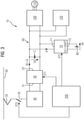
- FIG. 1 shows an exemplary embodiment of an arrangement 10, which can form part of a rail vehicle, in particular a rail vehicle, which is not shown in more detail for reasons of clarity.
- the arrangement 10 comprises a pantograph 20 or pantograph, which can be connected to a trackside contact wire or overhead line or a trackside conductor rail of a trackside, ie external, energy supply network 30 .
- the pantograph 20 is connected via a main switch 35 to a transformer 40 which is connected to a first connection side 51 of a converter 50 .
- a converter 50 is preferably a four-quadrant converter, which converts the alternating current of the energy supply network 30, which has been stepped down by the transformer 40, into a direct current with a voltage level that is as constant as possible for the direct voltage intermediate circuit.
- a second connection side 52 of the converter 50 is connected to a DC voltage intermediate circuit 60 .
- An intermediate circuit voltage Uz is present at the DC voltage intermediate circuit 60 .
- a DC voltage converter (DC/DC converter) 70 is also connected to the DC voltage intermediate circuit 60 with its first connection side 71 .
- a second connection side 72 of the DC voltage regulator 70 is connected to an energy store 80, for example a traction battery, as the arrangement's own energy supply device.
- converter 50 and DC voltage controller 70 can each be operated as a voltage source for DC voltage intermediate circuit 60, and during their voltage source operation they each try to set a predefined setpoint intermediate circuit voltage Usoll as the target voltage for DC voltage intermediate circuit 60.
- DC voltage intermediate circuit 60 is used to operate various components of the rail vehicle, for example to operate a pulse-controlled inverter 100 and a drive motor 110 connected to it and, for example, an auxiliary converter 120, which is connected to an on-board electrical system (not shown) of the rail vehicle and can feed it with energy.
- control device 200 which by means of a first control signal ST1 controls the converter 50 and controls the DC voltage controller 70 by means of a second control signal ST2.
- the control device 20 can initiate the opening and closing of the main switch 35 by means of a third control signal ST3.
- the control device 200 allows the following four operating modes: First operating mode of the arrangement 10: external energy supply operation when connected to the external energy supply network 30 ( figure 2 ).
- the DC link 60 is operated by the converter 50 as a voltage source.
- the control device 200 will use the first control signal ST1 to control the converter 50 in such a way that it sets the specified setpoint intermediate circuit voltage Usoll as the target voltage for the DC voltage intermediate circuit 60 .
- the DC voltage converter 70 is operated by the control device 200 using the second control signal ST2 as a charging device for the energy store 80 .
- the DC voltage controller 70 charges the energy storage device 80 by drawing energy from the DC voltage intermediate circuit 60 if the energy storage device 80 is not yet sufficiently charged, or leaves it disconnected from the DC voltage intermediate circuit 60 if the energy storage device 80 is sufficiently charged.
- the DC voltage controller 70 can compare the voltage Ub at the energy store 80 with a maximum storage voltage Umax and control the charging process according to the comparison result. If the maximum storage voltage Umax is less than the setpoint intermediate circuit voltage Usoll, then the DC voltage converter 70 operates in the charging mode, preferably in a current-controlled manner as a step-down converter.
- Second operating mode of the arrangement 10 energy storage operation without an external energy supply network 30 ( figure 3 ).
- the control device 200 will operate the DC voltage regulator 70 in its third operating mode, i.e. as a voltage source for the DC voltage intermediate circuit 60, specifically in such a way that the DC voltage controller 70 now attempts to generate the specified setpoint intermediate circuit voltage Usetpoint as the target voltage for the DC voltage intermediate circuit 60 .
- the converter 50 is preferably deactivated by means of the first control signal ST1, and the main switch 35 is also preferably opened by means of the third control signal ST3.
- DC voltage controller 70 As soon as DC voltage controller 70 is operating as a voltage source for DC voltage link 60, energy is fed from energy store 80 into DC voltage link 60 when the components connected to it, such as pulse-controlled inverter 100, drive motor 110, or auxiliary converter 120, require more energy from the DC voltage intermediate circuit 60 is removed than is fed. Otherwise, energy is taken from intermediate DC circuit 60 and fed into energy store 80, i.e. when the components mentioned feed energy in total or in total, for example when drive motor 110 feeds sufficient braking energy into intermediate DC circuit 60 during braking operation of the rail vehicle.
- Third operating mode of the arrangement 10 switching from the first operating mode to the second operating mode, ie from the external Energy supply mode in the energy storage mode ( Figure 4).
- the control device 200 will first switch to its third operating mode.
- the control device 200 will operate the converter 50 and the DC voltage controller 70 simultaneously or in parallel as a voltage source for the DC voltage intermediate circuit 60 .
- the control device 200 transmits target voltages of different levels to the converter 50 using the first control signal ST1 and to the DC voltage controller 70 using the second control signal ST2 specify for the DC link 60.
- the control device 200 specifies the setpoint intermediate circuit voltage Usoll as the target voltage for the DC voltage intermediate circuit 60 for the converter 50, whereas the DC voltage controller 70 specifies a smaller auxiliary voltage Uh.
- the auxiliary voltage Uh specified for the DC voltage controller 70 can only be 1,500 V.
- the auxiliary voltage Uh is preferably dimensioned so high that the components connected to the DC link 60, such as the pulse-controlled inverter 100, the drive motor 110 or the auxiliary converter 120, can continue to be operated with this voltage.
- the DC voltage controller 70 Since the DC voltage controller 70 is now switched from its first operating mode, in which it works as a charging device for the energy store 80, to its second operating mode, in which it works as a voltage source for generating the auxiliary voltage Uh, a certain delay in the Operation of the DC voltage controller 70 occur. In other words, the DC voltage controller 70 will not be able to switch abruptly from its first operating mode to its second operating mode. The control device 200 will monitor this delay in the transition from the first operating mode to the second operating mode by monitoring the current I1 flowing through the DC voltage converter 70 .
- the DC voltage controller 70 determines that it has reached a specified switching current value Is, it concludes that the DC voltage controller 70 has reached its second operating mode or is exercising it and - as desired - is attempting to use the auxiliary voltage Uh as the target voltage for the DC intermediate circuit 60 set. Since the auxiliary voltage Uh is less than the setpoint intermediate circuit voltage Usoll, when the DC voltage controller 70 is operated in its second operating mode, the DC voltage controller 70 conducts current from the DC voltage intermediate circuit 60 into the energy store 80, around the capacitor C of the DC voltage intermediate circuit 60 - outgoing from the setpoint intermediate circuit voltage Usoll set by the converter 50 and to lower the intermediate circuit voltage Uz to the value of the auxiliary voltage Uh.
- control device 200 As soon as the control device 200 has recognized that the current I1 through the DC voltage regulator 70 has reached the switching current value Is, it will deactivate the converter 50 so that the DC voltage intermediate circuit 60 is decoupled from the transformer 40 and from the main switch 35 . The control device 200 will then open the main switch 35, preferably by means of the third control signal ST3, in order to bring about a separation from the pantograph 20.
- the current I1 through the DC voltage converter 70 in the second operating mode and when switching over from the first operating mode to the second operating mode is limited by the control device 200 to a predetermined maximum current value in order to prevent damage to the DC voltage converter 70 and damage to the energy store 80 to avoid.
- the control device 200 can increase the target voltage for the DC voltage regulator 70 from the auxiliary voltage Uh to the setpoint intermediate circuit voltage Usoll, as a result of which the DC voltage regulator 70 is transferred to its third operating mode.
- Fourth operating mode of the arrangement 10 switching from the second operating mode to the first operating mode, ie from the energy storage mode to the external energy supply mode ( figure 5 ).
- a changeover from the energy supply mode to the converter mode preferably takes place as follows: First, the control device 200 will switch the DC voltage controller 70 from the third operating mode, in which it sets the target intermediate circuit voltage Usoll as the voltage source, to the second operating mode, in which the DC voltage controller 70 is to set a lower voltage as the target voltage, namely the auxiliary voltage Uh again . In other words, for the DC voltage controller 70, only the target voltage is lowered from the setpoint intermediate circuit voltage Usoll to the auxiliary voltage Uh.
- the converter 50 is activated. Since, after the converter 50 has been switched on, there is a certain switch-on delay before the converter is operating correctly will occur, the control device 200 will, for example, monitor the operation of the converter 50 after the converter 50 has been activated.
- the intermediate circuit voltage Uz is rising and exceeds the auxiliary voltage Uh, which is to be set by the DC voltage controller 70, then it concludes that the converter 50 has started its correct voltage source operation. As soon as the intermediate circuit voltage Uz corresponds to the specified setpoint intermediate circuit voltage Usetpoint, it will regard the converter 50 as being fully operational, so that the DC voltage controller 70 can be switched over from its second operating mode to its first operating mode, in which it works as a charging device.
- control device 200 can monitor the current I2 between the converter 50 and the DC link 60 and switch the DC voltage controller 70 to the first operating mode as soon as the current I2 flowing from the converter 50 into the DC link 60 exceeds a predetermined threshold value I2s .
- FIG. 1 shows an exemplary embodiment of an arrangement 10 in which the control device 200 has a converter control module 201 for controlling the converter 50 and a DC voltage converter module 202 for controlling the DC voltage converter 70. There is also a monitoring module 203, namely for monitoring the current I1 that flows into the DC voltage controller 70, for monitoring the current I2 that flows from the converter 50 into the DC voltage intermediate circuit 60, and/or for monitoring the intermediate circuit voltage Uz on the DC voltage intermediate circuit 60.
- control device 200 has a central module 204 which, on the basis of the monitoring results ERG from the monitoring module 203, controls the converter control module 201 and the DC voltage converter module 202 in such a way that converter 50 and DC voltage converter 70 operate in such a way like this above in connection with the Figures 1 to 5 has been explained. In this regard, the above explanations apply accordingly.
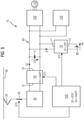
- the figure 7 shows an embodiment of an arrangement 10, in which the connection with the figure 6 shown modules of the control device 200 are arranged decentrally. It can thus be seen that the converter control module 201 is arranged in the converter 50 and the DC voltage converter module 202 in the DC voltage converter 70 or forms components of the converter 50 and the DC voltage converter 70 .
- the central module 204 and the monitoring module 203 are arranged separately.
Abstract
Eine Antriebsanordnung eines Schienenfahrzeugs weist zumindest einen Umrichter, der mit einer ersten Anschlussseite mit einem Energieversorgungsnetz verbindbar ist und mit einer zweiten Anschlussseite an einen Gleichspannungszwischenkreis angeschlossen ist, einen Gleichspannungssteller, der mit einer ersten Anschlussseite an den Gleichspannungszwischenkreis und mit einer zweiten Anschlussseite an eine anordnungseigene Energiebereitstellungseinrichtung angeschlossen ist, und eine Steuereinrichtung, die ausgestaltet ist, in einem Normalbetrieb wahlweise entweder den Umrichter oder den Gleichspannungssteller als Spannungsquelle für den Gleichspannungszwischenkreis zu betreiben und jeweils eine Sollzwischenkreisspannung als Zielspannung für den Gleichspannungszwischenkreis vorzugeben, auf. Ferner ist die Steuereinrichtung ausgestaltet, in einem Umschaltbetrieb den Umrichter und den Gleichspannungssteller gleichzeitig zu betreiben, wobei sie dem Umrichter und dem Gleichspannungssteller unterschiedliche Zielspannungen für den Gleichspannungszwischenkreis vorgibt.A drive arrangement of a rail vehicle has at least one converter, which can be connected to a power supply network with a first connection side and is connected to a DC voltage intermediate circuit with a second connection side, a DC voltage controller, which is connected with a first connection side to the DC voltage intermediate circuit and with a second connection side to an energy supply device belonging to the arrangement is connected, and a control device which is designed, in normal operation, to operate either the converter or the DC voltage controller as a voltage source for the DC voltage intermediate circuit and to specify a desired intermediate circuit voltage as the target voltage for the DC voltage intermediate circuit. Furthermore, the control device is designed to operate the converter and the DC voltage controller simultaneously in a switchover mode, specifying different target voltages for the DC voltage intermediate circuit for the converter and the DC voltage controller.
Description
Die Erfindung betrifft eine Antriebsanordnung eines Schienenfahrzeugs, deren Gleichspannungszwischenkreis über einen Umrichter mit einem Energieversorgungsnetz verbindbar ist und über einen Gleichspannungssteller mit einer anordnungseigene Energiebereitstellungseinrichtung verbunden ist.The invention relates to a drive arrangement of a rail vehicle, the DC voltage intermediate circuit of which can be connected to an energy supply network via a converter and is connected to an energy supply device of the arrangement itself via a DC voltage regulator.
Derartige Antriebsanordnungen ermöglichen, das Schienenfahrzeug sowohl in einem Batteriebetrieb als auch in einem Oberleitungsbetrieb betreiben zu können. Werden elektrifizierte Streckenabschnitte befahren, so wird das Schienenfahrzeug vorzugsweise mittels der von der Oberleitung bereitgestellten Energie betrieben, während ein Betrieb des Schienenfahrzeugs bei Befahren nicht elektrifizierter Streckenabschnitte mittels der eigenen Energiebereitstellungseinrichtung bzw. einer oder mehrerer auf dem Schienenfahrzeug angeordneter Batterie erfolgt.Such drive arrangements make it possible to operate the rail vehicle both in battery operation and in overhead line operation. If electrified route sections are traveled on, the rail vehicle is preferably operated using the energy provided by the overhead line, while the rail vehicle is operated when driving on non-electrified route sections using its own energy supply device or one or more batteries arranged on the rail vehicle.
Der Erfindung liegt die Aufgabe zugrunde, eine Anordnung anzugeben, die geringe Umschaltzeiten bei einem Umschalten zwischen Betriebsmodi der Antriebsanordnung ermöglicht.The invention is based on the object of specifying an arrangement that enables short switchover times when switching between operating modes of the drive arrangement.
Diese Aufgabe wird erfindungsgemäß durch eine Antriebsanordnung mit den Merkmalen gemäß Patentanspruch 1 gelöst. Vorteilhafte Ausgestaltungen sind in abhängigen Patentansprüchen angegeben.According to the invention, this object is achieved by a drive arrangement having the features according to patent claim 1 . Advantageous configurations are specified in the dependent patent claims.
Erfindungsgemäß weist die Antriebsanordnung eines Schienenfahrzeugs zumindest einen Umrichter, der mit einer ersten Anschlussseite mit einem Energieversorgungsnetz verbindbar ist und mit einer zweiten Anschlussseite an einen Gleichspannungszwischenkreis angeschlossen ist, einen Gleichspannungssteller, der mit einer ersten Anschlussseite an den Gleichspannungszwischenkreis und mit einer zweiten Anschlussseite an eine anordnungseigene Energiebereitstellungseinrichtung angeschlossen ist, und eine Steuereinrichtung, die ausgestaltet ist, in einem Normalbetrieb wahlweise entweder den Umrichter oder den Gleichspannungssteller als Spannungsquelle für den Gleichspannungszwischenkreis zu betreiben und jeweils eine Sollzwischenkreisspannung als Zielspannung für den Gleichspannungszwischenkreis vorzugeben, auf. Kennzeichnend ist die Steuereinrichtung ferner ausgestaltet, in einem Umschaltbetrieb den Umrichter und den Gleichspannungssteller gleichzeitig zu betreiben, wobei sie dem Umrichter und dem Gleichspannungssteller unterschiedliche Zielspannungen für den Gleichspannungszwischenkreis vorgibt.According to the invention, the drive arrangement of a rail vehicle has at least one converter, which can be connected to a power supply network with a first connection side and is connected to a DC voltage intermediate circuit with a second connection side, a DC voltage controller, which is connected with a first connection side to the DC voltage intermediate circuit and with a second connection side to an arrangement-specific Energy supply device is connected, and a control device that is designed is, in normal operation, to operate either the converter or the DC voltage controller as a voltage source for the DC voltage intermediate circuit and to specify a setpoint intermediate circuit voltage as the target voltage for the DC voltage intermediate circuit. Characteristically, the control device is also designed to operate the converter and the DC voltage controller simultaneously in a switchover mode, specifying different target voltages for the DC voltage intermediate circuit for the converter and the DC voltage controller.
Ein Vorteil der erfindungsgemäßen Anordnung ist darin zu sehen, dass bei dieser ein Umschalten der Energieversorgung des Gleichspannungszwischenkreises von der externen Energieversorgung zur anordnungseigenen bzw. internen Energieversorgung und umgekehrt verzögerungsfrei erfolgen kann, da während des Umschaltens, das bis zu einige Sekunden dauern kann, der Gleichspannungszwischenkreis dauerhaft gespeist wird, nämlich zumindest kurzzeitig sowohl von dem Gleichspannungssteller als Spannungsquelle als auch von dem Umrichter als Spannungsquelle. Um dabei zu vermeiden, dass der Betrieb zweier Spannungsquellen zu einer Instabilität des Gleichspannungszwischenkreises bzw. einer Instabilität des Umrichters und/oder Gleichspannungsstellers führt, ist erfindungsgemäß vorgesehen, dass während der Zeitspanne des Umschaltens bzw. des parallelen Betriebs von Umrichter und Gleichspannungssteller dem Umrichter und dem Gleichspannungssteller unterschiedliche Zielspannungen für den Gleichspannungszwischenkreis vorgegeben werden. Diese unterschiedliche Vorgabe an Zielspannungen ermöglicht es, dass beide Komponenten, also der Umrichter und der Gleichspannungssteller, stets stabil betrieben werden können und jeweils eine ausreichende Versorgung des Gleichspannungszwischenkreises gewährleistet wird, ohne dass es Regelprobleme bezüglich des Umrichterbetriebs oder des Gleichspannungsstellerbetriebs geben kann.An advantage of the arrangement according to the invention can be seen in the fact that the energy supply of the DC voltage intermediate circuit can be switched from the external energy supply to the arrangement's own or internal energy supply and vice versa without delay, since during the switching, which can last up to a few seconds, the DC voltage intermediate circuit is fed permanently, namely at least briefly both from the DC voltage controller as a voltage source and from the converter as a voltage source. In order to avoid that the operation of two voltage sources leads to an instability of the DC voltage intermediate circuit or an instability of the converter and/or DC voltage controller, it is provided according to the invention that during the period of switching or parallel operation of the converter and DC voltage controller, the converter and the DC voltage controller different target voltages for the DC link can be specified. This different specification of target voltages means that both components, i.e. the converter and the DC voltage controller, can always be operated stably and a sufficient supply of the DC voltage intermediate circuit is guaranteed without there being any control problems with regard to the converter operation or the DC voltage controller operation.
Ein weiterer Vorteil der erfindungsgemäßen Anordnung besteht darin, dass bei einem Wechsel von einer externen Energieversorgung auf eine fahrzeuginterne Energieversorgung im Bereich einer Ladestation bzw. einer Ladestrecke ein mit der Anordnung versehenes Schienenfahrzeug noch im Bereich der netzseitigen Energieversorgung beschleunigt werden kann und die Beschleunigung beim Verlassen des Bereichs ruckfrei aufrechterhalten bleiben kann, weil die fahrzeugeigene Energiebereitstellungseinrichtung den Wegfall der netzseitigen Energieversorgung nahtlos bzw. unterbrechungsfrei kompensiert.A further advantage of the arrangement according to the invention is that when changing from an external energy supply to a vehicle-internal energy supply in the area of a charging station or a charging section, a rail vehicle equipped with the arrangement can still be accelerated in the area of the mains-side energy supply and the acceleration can be maintained without jerks when leaving the area, because the on-board energy supply device seamlessly or .Compensated without interruption.
Mit Blick auf die Steuerung des Umrichters und des Gleichspannungsstellers wird es als vorteilhaft angesehen, wenn die Zielspannungen während des Umschaltens um zumindest 10% - bezogen auf die größere Zielspannung - voneinander abweichen. Schienenfahrzeugen kann die Abweichung der Zielspannungen vorzugsweise im Bereich zwischen 50 V und 200 V liegen und beispielsweise 100 V ± 10 V betragen.With regard to the control of the converter and the DC voltage controller, it is considered advantageous if the target voltages during switching differ from one another by at least 10%, based on the larger target voltage. In rail vehicles, the deviation in the target voltages can preferably be in the range between 50 V and 200 V and can be 100 V±10 V, for example.
Die Steuereinrichtung gibt während des gleichzeitigen Betriebs des Umrichters und des Gleichspannungsstellers dem Umrichter vorzugsweise als Zielspannung die Sollzwischenkreisspannung und dem Gleichspannungssteller als Zielspannung eine Hilfsspannung, die niedriger als die Sollzwischenkreisspannung ist, vor.During the simultaneous operation of the converter and the DC voltage controller, the control device preferably specifies the setpoint intermediate circuit voltage as the target voltage for the converter and an auxiliary voltage that is lower than the setpoint intermediate circuit voltage for the DC voltage controller as the target voltage.
Die Steuereinrichtung kann den Gleichspannungssteller vorzugsweise in zumindest drei Betriebsarten betreiben, nämlich in einer ersten Betriebsart, bei der der Gleichspannungssteller als Ladegerät für die anordnungseigene Energiebereitstellungseinrichtung arbeitet, in einer zweiten Betriebsart, bei der der Gleichspannungssteller als Zielspannung die Hilfsspannung einstellt, und in einer dritten Betriebsart, bei der der Gleichspannungssteller als Spannungsquelle arbeitet und als Zielspannung die Sollzwischenkreisspannung einstellt.The control device can preferably operate the DC voltage regulator in at least three operating modes, namely in a first operating mode, in which the DC voltage regulator operates as a charger for the arrangement's own energy supply device, in a second operating mode, in which the DC voltage regulator sets the auxiliary voltage as the target voltage, and in a third operating mode , in which the DC voltage controller works as a voltage source and sets the target intermediate circuit voltage as the target voltage.
Um bei einer Speisung des Gleichspannungszwischenkreises durch den Umrichter und einem parallelen Betrieb des Gleichspannungsstellers als Spannungsquelle eine Überlastung des Gleichspannungsstellers, der in der zweiten Betriebsart die Speisung durch den Umrichter zu kompensieren versucht, zu vermeiden, wird es als vorteilhaft angesehen, wenn insbesondere in der zweiten Betriebsart ein Stromfluss durch den Gleichspannungssteller auf einen vorgegebenen Maximalstromwert begrenzt wird.In order to avoid overloading of the DC voltage controller, which in the second mode of operation, when the DC voltage intermediate circuit is fed by the converter and the DC voltage controller is operated in parallel as a voltage source If attempts are made to compensate for feeding through the converter, it is considered advantageous if, in particular in the second operating mode, a current flow through the DC voltage controller is limited to a predetermined maximum current value.
Die Steuereinrichtung ist vorzugsweise ferner ausgestaltet, dass sie während des gleichzeitigen Betriebs des Umrichters und des Gleichspannungsstellers, bei einem Umschaltvorgang vom Umrichter als Spannungsquelle zum Gleichspannungssteller als Spannungsquelle, den Gleichspannungssteller in der zweiten Betriebsart betreibt und einen Strom durch den Gleichspannungssteller in Richtung der anordnungseigenen Energiebereitstellungseinrichtung überwacht und den Umrichter deaktiviert und den Gleichspannungssteller in die dritte Betriebsart schaltet, sobald der Strom durch den Gleichspannungssteller einen vorgegebenen Umschaltstromwert, insbesondere einen Maximalstromwert, erreicht.The control device is preferably also configured such that during the simultaneous operation of the converter and the DC voltage controller, during a switching process from the converter as the voltage source to the DC voltage controller as the voltage source, it operates the DC voltage controller in the second operating mode and monitors a current through the DC voltage controller in the direction of the arrangement's own energy supply device and deactivates the converter and switches the DC voltage controller to the third operating mode as soon as the current through the DC voltage controller reaches a predetermined switching current value, in particular a maximum current value.
Die Steuereinrichtung ist vorzugsweise derart ausgestaltet, dass sie während des gleichzeitigen Betriebs des Umrichters und des Gleichspannungsstellers, bei einem Umschaltvorgang vom Gleichspannungssteller als Spannungsquelle zum Umrichter als Spannungsquelle, den Gleichspannungssteller in der zweiten Betriebsart betreibt und die Zwischenkreisspannung überwacht und den Gleichspannungssteller in die erste Betriebsart schaltet, sobald die Zwischenkreisspannung eine vorgegebene Umschaltspannung, insbesondere die Sollzwischenkreisspannung, erreicht.The control device is preferably designed in such a way that during the simultaneous operation of the converter and the DC voltage controller, during a switching process from the DC voltage controller as the voltage source to the converter as the voltage source, it operates the DC voltage controller in the second operating mode and monitors the intermediate circuit voltage and switches the DC voltage controller to the first operating mode , as soon as the intermediate circuit voltage reaches a predetermined switching voltage, in particular the desired intermediate circuit voltage.
Alternativ oder zusätzlich kann in vorteilhafter Weise vorgesehen sein, dass die Steuereinrichtung während des gleichzeitigen Betriebs des Umrichters und des Gleichspannungsstellers, bei einem Umschaltvorgang vom Gleichspannungssteller als Spannungsquelle zum Umrichter als Spannungsquelle, den Gleichspannungssteller in der zweiten Betriebsart betreibt und den Stromfluss zwischen Umrichter und Gleichspannungszwischenkreis überwacht und den Gleichspannungssteller in die erste Betriebsart schaltet, sobald ein Strom von dem Umrichter in den Gleichspannungszwischenkreis fließt oder ein solcher Strom eine vorgegebene Stromschwelle überschreitet.Alternatively or additionally, it can advantageously be provided that the control device operates the DC voltage controller in the second operating mode and monitors the current flow between the converter and the DC voltage intermediate circuit during the simultaneous operation of the converter and the DC voltage controller, during a switching process from the DC voltage controller as the voltage source to the converter as the voltage source and the DC voltage regulator in the first mode switches as soon as a current flows from the converter into the DC link or such a current exceeds a predetermined current threshold.
Im Falle einer Energieeinspeisung durch zumindest eine an den Gleichspannungszwischenkreis angeschlossene elektrische Komponente und im Falle eines aktiven Umrichters wird die eingespeiste elektrische Energie vorzugsweise über den Umrichter in das Energieversorgungsnetz und über den Gleichspannungssteller in die anordnungseigene Energiebereitstellungseinrichtung gespeist, und im Falle eines deaktivierten Umrichters wird sie vorzugsweise über den Gleichspannungssteller in die anordnungseigene Energiebereitstellungseinrichtung eingespeist.In the case of energy being fed in by at least one electrical component connected to the intermediate DC voltage circuit and in the case of an active converter, the electrical energy fed in is preferably fed via the converter into the energy supply network and via the DC voltage controller into the arrangement's own energy supply device, and in the case of a deactivated converter it is preferably fed fed via the DC voltage controller into the arrangement's own energy supply device.
Die speisende zumindest eine Komponente ist vorzugsweise ein über einen Wechselrichter mit dem Gleichspannungszwischenkreis verbundener Traktionsmotor und/oder ein Hilfsbetriebeumrichter.The at least one feeding component is preferably a traction motor connected to the DC link via an inverter and/or an auxiliary converter.
Die Steuereinrichtung weist zur Ansteuerung des Umrichters vorzugsweise ein Umrichtersteuermodul, zur Ansteuerung des Gleichspannungsstellers ein Gleichspannungsstellermodul und zur Überwachung von Strom und/oder Spannung ein Überwachungsmodul auf.The control device preferably has a converter control module for controlling the converter, a DC converter module for controlling the DC voltage converter and a monitoring module for monitoring the current and/or voltage.
Vorteilhaft ist es dabei, wenn das Umrichtersteuermodul in dem Umrichter und das Gleichspannungsstellermodul in dem Gleichspannungssteller integriert ist.It is advantageous if the converter control module is integrated in the converter and the DC voltage controller module is integrated in the DC voltage controller.
Die anordnungseigene Energiebereitstellungseinrichtung kann eine oder mehrere Batterien umfassen bzw. durch eine oder mehrere Batterien gebildet sein ist. Bei einem Einsatz in einem Schienenfahrzeug umfasst die Energiebereitstellungseinrichtung vorzugsweise zumindest auch eine Batterie, insbesondere eine Traktionsbatterie. Die Energiebereitstellungseinrichtung kann ferner eine oder mehrere Brennstoffzellen umfassen.The arrangement's own power supply device can include one or more batteries or be formed by one or more batteries. When used in a rail vehicle, the energy supply device preferably also includes at least one battery, in particular a traction battery. The energy supply device can also include one or more fuel cells.
Die Erfindung bezieht sich darüber hinaus auf ein Schienenfahrzeug. Erfindungsgemäß ist vorgesehen, dass dieses zumindest eine erfindungsgemäße Antriebsanordnung aufweist.The invention also relates to a rail vehicle. According to the invention, it is provided that this has at least one drive arrangement according to the invention.
Bezüglich der Vorteile des erfindungsgemäßen Schienenfahrzeugs und vorteilhaften Ausgestaltungen sei auf die vorstehenden Ausführungen verwiesen. Erwähnt sei lediglich nochmals der Vorteil, dass bei einem Wechsel von einer externen Energieversorgung auf eine fahrzeuginterne Energieversorgung im Bereich einer Ladestation oder Ladestrecke das Schienenfahrzeug noch im Bereich der netzseitigen Energieversorgung beschleunigt werden kann, wobei beim Verlassen des netzseitigen Energieversorgungsbereichs die Beschleunigung ruckfrei aufrechterhalten bleiben kann, weil die fahrzeugeigene Energiebereitstellungseinrichtung den Wegfall der netzseitigen Energieversorgung nahtlos bzw. unterbrechungsfrei kompensieren kann.With regard to the advantages of the rail vehicle according to the invention and advantageous refinements, reference is made to the above statements. The advantage that should only be mentioned once again is that when changing from an external energy supply to an internal vehicle energy supply in the area of a charging station or charging section, the rail vehicle can still be accelerated in the area of the network-side energy supply, with the acceleration being able to be maintained smoothly when leaving the network-side energy supply area, because the vehicle's own energy supply device can compensate for the loss of the mains-side energy supply seamlessly or without interruption.
Die Erfindung bezieht sich darüber hinaus auf ein Verfahren zum Betreiben einer Antriebsanordnung, wobei die Antriebsanordnung zumindest einen Umrichter, der mit einer ersten Anschlussseite mit einem Energieversorgungsnetz verbindbar ist und mit einer zweiten Anschlussseite an einen Gleichspannungszwischenkreis angeschlossen ist, einen Gleichspannungssteller, der mit einer ersten Anschlussseite an den Gleichspannungszwischenkreis und mit einer zweiten Anschlussseite an eine anordnungseigene Energiebereitstellungseinrichtung angeschlossen ist, und eine Steuereinrichtung, welche in einem Normalbetrieb wahlweise entweder den Umrichter oder den Gleichspannungssteller als Spannungsquelle für den Gleichspannungszwischenkreis betreibt und jeweils eine Sollzwischenkreisspannung als Zielspannung für den Gleichspannungszwischenkreis vorgibt, aufweist. Kennzeichnend werden von der Steuereinrichtung in einem Umschaltbetrieb der Umrichter und der Gleichspannungssteller gleichzeitig betrieben, wobei sie dem Umrichter und dem Gleichspannungssteller unterschiedliche Zielspannungen für den Gleichspannungszwischenkreis vorgibt.The invention also relates to a method for operating a drive arrangement, wherein the drive arrangement has at least one converter, which can be connected to a power supply network with a first connection side and is connected to a DC voltage intermediate circuit with a second connection side, a DC voltage controller, which has a first connection side is connected to the DC voltage intermediate circuit and with a second connection side to an on-board energy supply device, and a control device which, in normal operation, optionally operates either the converter or the DC voltage controller as a voltage source for the DC voltage intermediate circuit and in each case specifies a desired intermediate circuit voltage as a target voltage for the DC voltage intermediate circuit. Characteristically, the converter and the DC voltage controller are operated simultaneously by the control device in a switchover mode, it specifying different target voltages for the DC voltage intermediate circuit for the converter and the DC voltage controller.
Bezüglich der Vorteile des erfindungsgemäßen Verfahrens sei wiederum auf die obigen Ausführungen im Zusammenhang mit der erfindungsgemäßen Antriebsanordnung verwiesen.With regard to the advantages of the method according to the invention, reference is again made to the above statements in connection with the drive arrangement according to the invention.
Die Erfindung wird nachfolgend anhand von Ausführungsbeispielen näher erläutert. Dabei zeigen beispielhaft
- Fig. 1-5
- ein erstes Ausführungsbeispiel für eine Anordnung, die einen Bestandteil eines Schienenfahrzeugs bildet, wobei die
Figuren 2 bis 4 unterschiedliche Betriebsmodi der Anordnung darstellen, - Fig. 6
- ein zweites Ausführungsbeispiel für eine Anordnung, die einen Bestandteil eines Schienenfahrzeugs bildet, und
- Fig. 7
- ein drittes Ausführungsbeispiel für eine Anordnung, die einen Bestandteil eines Schienenfahrzeugs bildet.
- Figures 1-5
- a first embodiment of an arrangement which forms part of a rail vehicle, wherein the
Figures 2 to 4 represent different operating modes of the arrangement, - 6
- a second exemplary embodiment of an arrangement which forms part of a rail vehicle, and
- Figure 7
- a third exemplary embodiment of an arrangement which forms part of a rail vehicle.
In den Figuren werden für identische oder vergleichbare Komponenten stets dieselben Bezugszeichen verwendet.In the figures, the same reference numbers are always used for identical or comparable components.
Die
Der Pantograph 20 steht über einen Hauptschalter 35 mit einem Transformator 40 in Verbindung, der an eine erste Anschlussseite 51 eines Umrichters 50 angeschlossen ist. Bei dem Umrichter 50 handelt es sich vorzugsweise um einen Vierquadrantensteller, welcher den von dem Transformator 40 heruntertransformierten Wechselstrom des Energieversorgungsnetzes 30 in einen Gleichstrom mit einem möglichst konstanten Spannungsniveau für den Gleichspannungszwischenkreis wandelt.The
Eine zweite Anschlussseite 52 des Umrichters 50 steht mit einem Gleichspannungszwischenkreis 60 in Verbindung. An dem Gleichspannungszwischenkreis 60 liegt eine Zwischenkreisspannung Uz an.A
An den Gleichspannungszwischenkreis 60 ist außerdem ein Gleichspannungssteller (DC/DC-Steller) 70 mit seiner ersten Anschlussseite 71 angeschlossen. Eine zweite Anschlussseite 72 des Gleichspannungsstellers 70 steht mit einem Energiespeicher 80, beispielsweise einer Traktionsbatterie, als anordnungseigener Energiebereitstellungseinrichtung in Verbindung.A DC voltage converter (DC/DC converter) 70 is also connected to the DC voltage
Der Umrichter 50 und der Gleichspannungssteller 70 können jeweils, wie weiter unten noch im Detail erläutert werden wird, als Spannungsquelle für den Gleichspannungszwischenkreis 60 betrieben werden, wobei sie während ihres Spannungsquellenbetriebs jeweils versuchen, eine vorgegebene Sollzwischenkreisspannung Usoll als Zielspannung für den Gleichspannungszwischenkreis 60 einzustellen.As will be explained in detail further below,
Der Gleichspannungszwischenkreis 60 dient zum Betrieb verschiedener Komponenten des Schienenfahrzeugs, beispielsweise für den Betrieb eines Pulswechselrichters 100 und eines daran angeschlossenen Antriebsmotors 110 sowie beispielweise eines Hilfsbetriebeumrichters 120, der an ein nicht weiter dargestelltes Bordnetz des Schienenfahrzeugs angeschlossen ist und dieses mit Energie speisen kann.DC voltage
Zur Ansteuerung des Umrichters 50 und des Gleichspannungsstellers 70 weist die Anordnung 10 gemäß
Die Steuereinrichtung 200 gemäß
Erster Betriebsmodus der Anordnung 10: Externer Energieversorgungsbetrieb bei Anschluss an das externe Energieversorgungsnetz 30 (
First operating mode of the arrangement 10: external energy supply operation when connected to the external energy supply network 30 (
Ist das externe Energieversorgungsnetz 30 verfügbar bzw. befindet sich das mit der Anordnung 10 ausgestattete Schienenfahrzeug im Bereich eines Fahrdrahts oder einer Fahrschiene des externen Energieversorgungsnetzes 30, so wird der Gleichspannungszwischenkreis 60 von dem Umrichter 50 als Spannungsquelle betrieben. Zu diesem Zweck wird die Steuereinrichtung 200 mittels des ersten Steuersignals ST1 den Umrichter 50 derart ansteuern, dass dieser die vorgegebene Sollzwischenkreisspannung Usoll als Zielspannung für den Gleichspannungszwischenkreis 60 einstellt.If the external
Der Gleichspannungssteller 70 wird von der Steuereinrichtung 200 mittels des zweiten Steuersignals ST2 als Ladegerät für den Energiespeicher 80 betrieben. Dies bedeutet, dass der Gleichspannungssteller 70 den Energiespeicher 80 durch Energieentnahme aus dem Gleichspannungszwischenkreis 60 lädt, wenn der Energiespeicher 80 noch nicht ausreichend geladen ist, oder von dem Gleichspannungszwischenkreis 60 getrennt lässt, wenn der Energiespeicher 80 ausreichend geladen ist. Beispielsweise kann der Gleichspannungssteller 70 die Spannung Ub am Energiespeicher 80 mit einer maximalen Speicherspannung Umax vergleichen und den Ladevorgang entsprechend dem Vergleichsergebnis steuern. Ist die maximale Speicherspannung Umax kleiner als die Sollzwischenkreisspannung Usoll, so arbeitet der Gleichspannungssteller 70 im Ladebetrieb vorzugsweise stromgeregelt als Tiefsetzsteller.The
Zweiter Betriebsmodus der Anordnung 10: Energiespeicherbetrieb ohne externes Energieversorgungsnetz 30 (
Ist kein Anschluss an das externe Energieversorgungsnetz 30 möglich, beispielsweise weil der von dem Schienenfahrzeug befahrene Streckenabschnitt keinen entsprechenden Fahrdraht oder Stromschiene aufweist, so wird die Steuereinrichtung 200 den Gleichspannungssteller 70 in dessen dritter Betriebsart, also als Spannungsquelle für den Gleichspannungszwischenkreis 60, betreiben, und zwar derart, dass nun der Gleichspannungssteller 70 versucht, die vorgegebene Sollzwischenkreisspannung Usoll als Zielspannung für den Gleichspannungszwischenkreis 60 zu erzeugen.If no connection to the external
Mittels des ersten Steuersignals ST1 wird der Umrichter 50 vorzugsweise deaktiviert, außerdem wird vorzugsweise der Hauptschalter 35 mittels des dritten Steuersignals ST3 geöffnet.The
Sobald der Gleichspannungssteller 70 als Spannungsquelle für den Gleichspannungszwischenkreis 60 arbeitet, wird Energie aus dem Energiespeicher 80 in den Gleichspannungszwischenkreis 60 eingespeist, wenn seitens der daran angeschlossenen Komponenten wie beispielsweise seitens des Pulswechselrichters 100, seitens des Antriebsmotors 110 oder seitens des Hilfsbetriebeumrichters 120 mehr Energie aus dem Gleichspannungszwischenkreis 60 entnommen wird als eingespeist wird. Andernfalls wird Energie aus dem Gleichspannungszwischenkreis 60 entnommen und in den Energiespeicher 80 eingespeist, also wenn die genannten Komponenten insgesamt bzw. in Summe Energie einspeisen, wenn beispielweise im Bremsbetrieb des Schienenfahrzeugs der Antriebsmotor 110 ausreichend viel Bremsenergie in den Gleichspannungszwischenkreis 60 einspeist.As soon as
Dritter Betriebsmodus der Anordnung 10: Umschalten vom ersten Betriebsmodus in den zweiten Betriebsmodus, also vom externen Energieversorgungsbetrieb in den Energiespeicherbetrieb (Figur 4) .Third operating mode of the arrangement 10: switching from the first operating mode to the second operating mode, ie from the external Energy supply mode in the energy storage mode (Figure 4).
Soll von dem ersten Betriebsmodus, bei dem der Umrichter 50 als Spannungsquelle arbeitet, in den zweiten Betriebsmodus, bei dem der Gleichspannungssteller 70 in seiner dritten Betriebsart bzw. als alleinige Spannungsquelle arbeitet, umgeschaltet werden, weil beispielsweise der noch befahrene elektrifizierte Streckenabschnitt in Kürze verlassen wird, so wird die Steuereinrichtung 200 zunächst in ihren dritten Betriebsmodus schalten.If the first operating mode, in which the
Im dritten Betriebsmodus wird die Steuereinrichtung 200 den Umrichter 50 und den Gleichspannungssteller 70 gleichzeitig bzw. parallel als Spannungsquelle für den Gleichspannungszwischenkreis 60 betreiben. Um dabei eine Instabilität bezüglich der Regelung des Umrichters 50 und der Regelung des Gleichspannungsstellers 70 zu vermeiden, wird zur Entkopplung des Umrichterbetriebs und des Gleichspannungsstellerbetriebs die Steuereinrichtung 200 mittels des ersten Steuersignals ST1 dem Umrichter 50 und mittels des zweiten Steuersignals ST2 dem Gleichspannungssteller 70 unterschiedlich hohe Zielspannungen für den Gleichspannungszwischenkreis 60 vorgeben. Beispielsweise kann vorgesehen sein, dass die Steuereinrichtung 200 dem Umrichter 50 die Sollzwischenkreisspannung Usoll als Zielspannung für den Gleichspannungszwischenkreis 60 vorgibt, wohingegen dem Gleichspannungssteller 70 eine kleinere Hilfsspannung Uh vorgegeben wird. Beträgt die Sollzwischenkreisspannung beispielsweise 1.600 V, so kann die dem Gleichspannungssteller 70 vorgegebene Hilfsspannung Uh nur 1.500 V betragen. Die Hilfsspannung Uh ist vorzugsweise derart hoch bemessen, dass die an den Gleichspannungszwischenkreis 60 angeschlossenen Komponenten wie beispielsweise der Pulswechselrichter 100, der Antriebsmotor 110 oder der Hilfsbetriebeumrichter 120 mit dieser Spannung weiter betrieben werden können.In the third operating mode, the
Da der Gleichspannungssteller 70 von seiner ersten Betriebsart, bei der er als Ladegerät für den Energiespeicher 80 arbeitet, nun in seine zweite Betriebsart, bei der er als Spannungsquelle zur Erzeugung der Hilfsspannung Uh arbeitet, umgestellt wird, kann bzw. wird eine gewisse Verzögerung in der Arbeitsweise des Gleichspannungsstellers 70 auftreten. Mit anderen Worten wird der Gleichspannungssteller 70 nicht abrupt von seiner ersten Betriebsart in seine zweite Betriebsart wechseln können. Diese Verzögerung des Übergangs von der ersten Betriebsart in die zweite Betriebsart wird die Steuereinrichtung 200 überwachen, indem sie den Strom I1, der durch den Gleichspannungssteller 70 fließt, überwacht.Since the
Stellt sie bei der Überwachung des Stromes I1 fest, dass dieser einen vorgegebenen Umschaltstromwert Is erreicht, so schließt sie daraus, dass der Gleichspannungssteller 70 seine zweite Betriebsart erreicht hat bzw. diese ausübt und - wie gewünscht - versucht, die Hilfsspannung Uh als Zielspannung für den Gleichspannungszwischenkreis 60 einzustellen. Da die Hilfsspannung Uh kleiner als die Sollzwischenkreisspannung Usoll ist, wird es nämlich beim Betrieb des Gleichspannungsstellers 70 in dessen zweiter Betriebsart dazu kommen, dass der Gleichspannungssteller 70 Strom aus dem Gleichspannungszwischenkreis 60 in den Energiespeicher 80 leitet, um den Kondensator C des Gleichspannungszwischenkreises 60 - ausgehend von der von dem Umrichter 50 eingestellten Sollzwischenkreisspannung Usoll - zu entladen und die Zwischenkreisspannung Uz auf den Wert der Hilfsspannung Uh abzusenken.If, when monitoring the current I1, it determines that it has reached a specified switching current value Is, it concludes that the
Sobald die Steuereinrichtung 200 erkannt hat, dass der Strom I1 durch den Gleichspannungssteller 70 den Umschaltstromwert Is erreicht hat, wird sie den Umrichter 50 deaktivieren, sodass der Gleichspannungszwischenkreis 60 vom Transformator 40 und vom Hauptschalter 35 entkoppelt wird. Anschließend wird die Steuereinrichtung 200 vorzugsweise mittels des dritten Steuersignals ST3 den Hauptschalter 35 öffnen, um eine Trennung vom Pantographen 20 herbeizuführen.As soon as the
Vorteilhaft ist es, wenn der Strom I1 durch den Gleichspannungssteller 70 in der zweiten Betriebsart sowie beim Umschalten von der ersten Betriebsart in die zweite Betriebsart von der Steuereinrichtung 200 auf einen vorgegebenen Maximalstromwert begrenzt wird, um eine Beschädigung des Gleichspannungsstellers 70 und eine Beschädigung des Energiespeichers 80 zu vermeiden.It is advantageous if the current I1 through the
Nachdem der Umrichter 50 abgeschaltet worden ist, kann die Steuereinrichtung 200 die Zielspannung für den Gleichspannungssteller 70 von der Hilfsspannung Uh auf die Sollzwischenkreisspannung Usoll erhöhen, wodurch der Gleichspannungssteller 70 in seine dritte Betriebsart überführt wird.After the
Vierter Betriebsmodus der Anordnung 10: Umschalten vom zweiten Betriebsmodus in den ersten Betriebsmodus, also vom Energiespeicherbetrieb in den externen Energieversorgungsbetrieb (
Wird die Anordnung 10 mit dem Gleichspannungssteller 70 als Spannungsquelle für den Gleichspannungszwischenkreis 60 betrieben und ist der Umrichter 50 deaktiviert, so erfolgt ein Umstellen vom Energieversorgungsbetrieb in den Umrichterbetrieb vorzugsweise wie folgt:
Zunächst wird die Steuereinrichtung 200 den Gleichspannungssteller 70 von der dritten Betriebsart, bei der dieser als Spannungsquelle die Sollzwischenkreisspannung Usoll als Zielspannung einstellt, in die zweite Betriebsart umschalten, bei der der Gleichspannungssteller 70 als Zielspannung eine kleinere Spannung, nämlich wieder die Hilfsspannung Uh, einstellen soll. Mit anderen Worten wird für den Gleichspannungssteller 70 lediglich die Zielspannung von der Sollzwischenkreisspannung Usoll auf die Hilfsspannung Uh abgesenkt.If the
First, the
Gleichzeitig oder danach wird der Umrichter 50 aktiviert. Da nach dem Einschalten des Umrichters 50 eine gewisse Einschaltverzögerung bis zu einem korrekten Umrichterbetrieb auftreten wird, wird die Steuereinrichtung 200 nach dem Aktivieren des Umrichters 50 beispielsweise den Betrieb des Umrichters 50 überwachen.At the same time or thereafter, the
Stellt sie dabei fest, dass die Zwischenkreisspannung Uz ansteigt und die Hilfsspannung Uh, die vom Gleichspannungssteller 70 eingestellt werden soll, überschreitet, so schließt sie daraus, dass der Umrichter 50 seinen korrekten Spannungsquellenbetrieb aufgenommen hat. Sobald die Zwischenkreisspannung Uz der vorgegebenen Sollzwischenkreisspannung Usoll entspricht, wird sie den Umrichter 50 als vollständig im Betrieb befindlich ansehen, sodass der Gleichspannungssteller 70 von seiner zweiten Betriebsart in seine erste Betriebsart, bei der er als Ladegerät arbeitet, umgeschaltet werden kann.If it establishes that the intermediate circuit voltage Uz is rising and exceeds the auxiliary voltage Uh, which is to be set by the
Alternativ oder zusätzlich kann die Steuereinrichtung 200 den Strom I2 zwischen dem Umrichter 50 und dem Gleichspannungszwischenkreis 60 überwachen und den Gleichspannungssteller 70 in die erste Betriebsart schalten, sobald der Strom I2, der von dem Umrichter 50 in den Gleichspannungszwischenkreis 60 fließt, einen vorgegebenen Schwellenwert I2s überschreitet.Alternatively or additionally, the
Die
Darüber hinaus weist die Steuereinrichtung 200 ein Zentralmodul 204 auf, das auf der Basis der Überwachungsergebnisse ERG des Überwachungsmoduls 203 das Umrichtersteuermodul 201 und das Gleichspannungsstellermodul 202 ansteuert, und zwar derart, dass Umrichter 50 und Gleichspannungssteller 70 so arbeiten, wie dies oben im Zusammenhang mit den
Die
Im Übrigen gelten die obigen Erläuterungen im Zusammenhang mit den
- 1010
- Anordnungarrangement
- 2020
- Pantographpantograph
- 3030
- externes Energieversorgungsnetzexternal power supply network
- 3535
- Hauptschaltermain switch
- 4040
- Transformatortransformer
- 5050
- Umrichterconverter
- 5151
- erste Anschlussseitefirst connection side
- 5252
- zweite Anschlussseitesecond connection side
- 6060
- GleichspannungszwischenkreisDC intermediate circuit
- 7070
- Gleichspannungssteller / DC/DC-StellerDC voltage regulator / DC/DC regulator
- 7171
- erste Anschlussseitefirst connection side
- 7272
- zweite Anschlussseitesecond connection side
- 8080
- Energiebereitstellungseinrichtung / EnergiespeicherEnergy supply device / energy storage
- 100100
- Pulswechselrichterpulse inverter
- 110110
- Antriebsmotordrive motor
- 120120
- Hilfsbetriebeumrichterauxiliary converter
- 200200
- Steuereinrichtungcontrol device
- 201201
- Umrichtersteuermodulinverter control module
- 202202
- GleichspannungsstellermodulDC voltage regulator module
- 203203
- Überwachungsmodulmonitoring module
- 204204
- Zentralmodulcentral module
- CC
- Kondensatorcapacitor
- ERGERG
- Überwachungsergebnismonitoring result
- I1I1
- Stromcurrent
- I2I2
- Stromcurrent
- I2sI2s
- Stromschwellecurrent threshold
- Isis
- Umschaltstromwertswitching current value
- ST1ST1
- erstes Steuersignalfirst control signal
- ST2ST2
- zweites Steuersignalsecond control signal
- ST3ST3
- drittes Steuersignalthird control signal
- UbUb
- Spannungvoltage
- Uhuh
- Hilfsspannungauxiliary voltage
- Umaxmax
- maximale Speicherspannungmaximum memory voltage
- Usollusol
- Sollzwischenkreisspannungtarget intermediate circuit voltage
- UzUz
- Zwischenkreisspannungintermediate circuit voltage
Claims (15)
Applications Claiming Priority (1)
| Application Number | Priority Date | Filing Date | Title |
|---|---|---|---|
| DE102020211315.7A DE102020211315A1 (en) | 2020-09-09 | 2020-09-09 | Arrangement with converter and DC voltage controller |
Publications (1)
| Publication Number | Publication Date |
|---|---|
| EP3967544A1 true EP3967544A1 (en) | 2022-03-16 |
Family
ID=77627011
Family Applications (1)
| Application Number | Title | Priority Date | Filing Date |
|---|---|---|---|
| EP21194551.4A Pending EP3967544A1 (en) | 2020-09-09 | 2021-09-02 | Drive assembly for a rail vehicle |
Country Status (2)
| Country | Link |
|---|---|
| EP (1) | EP3967544A1 (en) |
| DE (1) | DE102020211315A1 (en) |
Cited By (1)
| Publication number | Priority date | Publication date | Assignee | Title |
|---|---|---|---|---|
| WO2024046734A1 (en) * | 2022-08-30 | 2024-03-07 | Siemens Mobility GmbH | Arrangement for driving a rail vehicle |
Citations (2)
| Publication number | Priority date | Publication date | Assignee | Title |
|---|---|---|---|---|
| CN106042957A (en) * | 2016-06-01 | 2016-10-26 | 北京交通大学 | Excessive phase control strategy for traction converter of hybrid power motor train unit |
| DE102018203015B3 (en) * | 2018-02-28 | 2019-05-09 | Siemens Aktiengesellschaft | Method for controlling a battery current of a traction battery |
Family Cites Families (4)
| Publication number | Priority date | Publication date | Assignee | Title |
|---|---|---|---|---|
| JP3900822B2 (en) | 2000-11-16 | 2007-04-04 | 株式会社豊田自動織機 | A power supply circuit for a mobile unit that is powered without contact |
| KR101003657B1 (en) | 2006-08-09 | 2010-12-23 | 미쓰비시덴키 가부시키가이샤 | Power converter and controller using such power converter for electric rolling stock |
| JP4958846B2 (en) | 2008-06-03 | 2012-06-20 | 株式会社日立製作所 | Vehicle control device for intermittent power reception |
| DE102017213306A1 (en) | 2017-08-01 | 2019-02-07 | Siemens Aktiengesellschaft | Energy supply device for a rail vehicle |
-
2020
- 2020-09-09 DE DE102020211315.7A patent/DE102020211315A1/en active Pending
-
2021
- 2021-09-02 EP EP21194551.4A patent/EP3967544A1/en active Pending
Patent Citations (2)
| Publication number | Priority date | Publication date | Assignee | Title |
|---|---|---|---|---|
| CN106042957A (en) * | 2016-06-01 | 2016-10-26 | 北京交通大学 | Excessive phase control strategy for traction converter of hybrid power motor train unit |
| DE102018203015B3 (en) * | 2018-02-28 | 2019-05-09 | Siemens Aktiengesellschaft | Method for controlling a battery current of a traction battery |
Cited By (1)
| Publication number | Priority date | Publication date | Assignee | Title |
|---|---|---|---|---|
| WO2024046734A1 (en) * | 2022-08-30 | 2024-03-07 | Siemens Mobility GmbH | Arrangement for driving a rail vehicle |
Also Published As
| Publication number | Publication date |
|---|---|
| DE102020211315A1 (en) | 2022-03-10 |
Similar Documents
| Publication | Publication Date | Title |
|---|---|---|
| DE102011109709B4 (en) | Method and system for supplying voltage to an on-board network of a vehicle | |
| EP3137335B1 (en) | Control for electrically driven vehicle, electrically driven vehicle having control, and method | |
| DE102014006028B4 (en) | Multi-battery system to increase the electric range | |
| DE102015206259A1 (en) | ACTIVE INSULATED CIRCUIT FOR PRE-LOADING AND UNLOADING A HIGH VOLTAGE BUSH | |
| EP3634803B1 (en) | Power supply for a rail vehicle | |
| EP3556594B1 (en) | Vehicle and method for operating a vehicle | |
| DE112021002720T5 (en) | power supply system | |
| EP3544844A1 (en) | Operating method for a dual-voltage battery | |
| DE102018131363A1 (en) | Method for operating a high-voltage network in an electric or hybrid vehicle, high-voltage network for an electric or hybrid vehicle and electric or hybrid vehicle | |
| WO2014079603A2 (en) | Electrical circuit arrangement for an electrically driven vehicle, vehicle and corresponding method | |
| WO2018219643A1 (en) | Discharge circuit and method for discharging a high-voltage dc link of a vehicle | |
| EP3967544A1 (en) | Drive assembly for a rail vehicle | |
| DE102011118716A1 (en) | Storage system for e.g. supplying electrical energy for electric drive of electric car, has semiconductor switch connected in series with contactors and accumulator, and blocking in opened bidirectional manner | |
| DE102018218312A1 (en) | Energy supply arrangement for supplying an electrical consumer of a low-voltage electrical system of a motor vehicle, electrical system and method for operating an energy supply arrangement | |
| DE102020204336B4 (en) | Vehicle-side high-voltage charging circuit and vehicle electrical system | |
| WO2020254470A1 (en) | Circuit assembly for a motor vehicle, and method for adapting the voltage of a high-voltage dc intermediate circuit in a motor vehicle | |
| WO2020020612A1 (en) | Electrical energy system comprising fuel cells | |
| WO2018108495A1 (en) | Electrical machine arrangement | |
| WO2024068113A1 (en) | Dc-dc converter device, power supply system and method for discharging a dc link capacitor | |
| WO2004080747A1 (en) | Hybrid driving system and an method for adjusting said hybrid driving system | |
| DE102021116525A1 (en) | Device and method for the electrical supply of a low-voltage on-board network of a motor vehicle, in particular an electric motor vehicle | |
| WO2023036495A1 (en) | Method and device for operating an electrically driven vehicle | |
| EP4344424A1 (en) | Method and energy transfer circuit for transferring electrical energy between a vehicle-side high-voltage battery and a vehicle-external high-voltage device | |
| DE102015012677A1 (en) | Method and device for energy management in a motor vehicle with at least two driven vehicle axles | |
| DE102019128424A1 (en) | Method for operating a motor vehicle and motor vehicle |
Legal Events
| Date | Code | Title | Description |
|---|---|---|---|
| PUAI | Public reference made under article 153(3) epc to a published international application that has entered the european phase |
Free format text: ORIGINAL CODE: 0009012 |
|
| STAA | Information on the status of an ep patent application or granted ep patent |
Free format text: STATUS: THE APPLICATION HAS BEEN PUBLISHED |
|
| AK | Designated contracting states |
Kind code of ref document: A1 Designated state(s): AL AT BE BG CH CY CZ DE DK EE ES FI FR GB GR HR HU IE IS IT LI LT LU LV MC MK MT NL NO PL PT RO RS SE SI SK SM TR |
|
| STAA | Information on the status of an ep patent application or granted ep patent |
Free format text: STATUS: REQUEST FOR EXAMINATION WAS MADE |
|
| 17P | Request for examination filed |
Effective date: 20220916 |
|
| RBV | Designated contracting states (corrected) |
Designated state(s): AL AT BE BG CH CY CZ DE DK EE ES FI FR GB GR HR HU IE IS IT LI LT LU LV MC MK MT NL NO PL PT RO RS SE SI SK SM TR |