EP3967544A1 - Agencement d'entraînement d'un véhicule ferroviaire - Google Patents
Agencement d'entraînement d'un véhicule ferroviaire Download PDFInfo
- Publication number
- EP3967544A1 EP3967544A1 EP21194551.4A EP21194551A EP3967544A1 EP 3967544 A1 EP3967544 A1 EP 3967544A1 EP 21194551 A EP21194551 A EP 21194551A EP 3967544 A1 EP3967544 A1 EP 3967544A1
- Authority
- EP
- European Patent Office
- Prior art keywords
- voltage
- converter
- intermediate circuit
- arrangement
- controller
- Prior art date
- Legal status (The legal status is an assumption and is not a legal conclusion. Google has not performed a legal analysis and makes no representation as to the accuracy of the status listed.)
- Pending
Links
Images


Classifications
-
- B—PERFORMING OPERATIONS; TRANSPORTING
- B60—VEHICLES IN GENERAL
- B60L—PROPULSION OF ELECTRICALLY-PROPELLED VEHICLES; SUPPLYING ELECTRIC POWER FOR AUXILIARY EQUIPMENT OF ELECTRICALLY-PROPELLED VEHICLES; ELECTRODYNAMIC BRAKE SYSTEMS FOR VEHICLES IN GENERAL; MAGNETIC SUSPENSION OR LEVITATION FOR VEHICLES; MONITORING OPERATING VARIABLES OF ELECTRICALLY-PROPELLED VEHICLES; ELECTRIC SAFETY DEVICES FOR ELECTRICALLY-PROPELLED VEHICLES
- B60L50/00—Electric propulsion with power supplied within the vehicle
- B60L50/50—Electric propulsion with power supplied within the vehicle using propulsion power supplied by batteries or fuel cells
- B60L50/53—Electric propulsion with power supplied within the vehicle using propulsion power supplied by batteries or fuel cells in combination with an external power supply, e.g. from overhead contact lines
-
- B—PERFORMING OPERATIONS; TRANSPORTING
- B60—VEHICLES IN GENERAL
- B60L—PROPULSION OF ELECTRICALLY-PROPELLED VEHICLES; SUPPLYING ELECTRIC POWER FOR AUXILIARY EQUIPMENT OF ELECTRICALLY-PROPELLED VEHICLES; ELECTRODYNAMIC BRAKE SYSTEMS FOR VEHICLES IN GENERAL; MAGNETIC SUSPENSION OR LEVITATION FOR VEHICLES; MONITORING OPERATING VARIABLES OF ELECTRICALLY-PROPELLED VEHICLES; ELECTRIC SAFETY DEVICES FOR ELECTRICALLY-PROPELLED VEHICLES
- B60L2200/00—Type of vehicles
- B60L2200/26—Rail vehicles
-
- Y—GENERAL TAGGING OF NEW TECHNOLOGICAL DEVELOPMENTS; GENERAL TAGGING OF CROSS-SECTIONAL TECHNOLOGIES SPANNING OVER SEVERAL SECTIONS OF THE IPC; TECHNICAL SUBJECTS COVERED BY FORMER USPC CROSS-REFERENCE ART COLLECTIONS [XRACs] AND DIGESTS
- Y02—TECHNOLOGIES OR APPLICATIONS FOR MITIGATION OR ADAPTATION AGAINST CLIMATE CHANGE
- Y02T—CLIMATE CHANGE MITIGATION TECHNOLOGIES RELATED TO TRANSPORTATION
- Y02T10/00—Road transport of goods or passengers
- Y02T10/60—Other road transportation technologies with climate change mitigation effect
- Y02T10/70—Energy storage systems for electromobility, e.g. batteries
Definitions
- the invention relates to a drive arrangement of a rail vehicle, the DC voltage intermediate circuit of which can be connected to an energy supply network via a converter and is connected to an energy supply device of the arrangement itself via a DC voltage regulator.
- Such drive arrangements make it possible to operate the rail vehicle both in battery operation and in overhead line operation. If electrified route sections are traveled on, the rail vehicle is preferably operated using the energy provided by the overhead line, while the rail vehicle is operated when driving on non-electrified route sections using its own energy supply device or one or more batteries arranged on the rail vehicle.
- the invention is based on the object of specifying an arrangement that enables short switchover times when switching between operating modes of the drive arrangement.
- the drive arrangement of a rail vehicle has at least one converter, which can be connected to a power supply network with a first connection side and is connected to a DC voltage intermediate circuit with a second connection side, a DC voltage controller, which is connected with a first connection side to the DC voltage intermediate circuit and with a second connection side to an arrangement-specific Energy supply device is connected, and a control device that is designed is, in normal operation, to operate either the converter or the DC voltage controller as a voltage source for the DC voltage intermediate circuit and to specify a setpoint intermediate circuit voltage as the target voltage for the DC voltage intermediate circuit.
- the control device is also designed to operate the converter and the DC voltage controller simultaneously in a switchover mode, specifying different target voltages for the DC voltage intermediate circuit for the converter and the DC voltage controller.
- An advantage of the arrangement according to the invention can be seen in the fact that the energy supply of the DC voltage intermediate circuit can be switched from the external energy supply to the arrangement's own or internal energy supply and vice versa without delay, since during the switching, which can last up to a few seconds, the DC voltage intermediate circuit is fed permanently, namely at least briefly both from the DC voltage controller as a voltage source and from the converter as a voltage source.
- the converter and the DC voltage controller different target voltages for the DC link can be specified.
- This different specification of target voltages means that both components, i.e. the converter and the DC voltage controller, can always be operated stably and a sufficient supply of the DC voltage intermediate circuit is guaranteed without there being any control problems with regard to the converter operation or the DC voltage controller operation.
- a further advantage of the arrangement according to the invention is that when changing from an external energy supply to a vehicle-internal energy supply in the area of a charging station or a charging section, a rail vehicle equipped with the arrangement can still be accelerated in the area of the mains-side energy supply and the acceleration can be maintained without jerks when leaving the area, because the on-board energy supply device seamlessly or .Compensated without interruption.
- the target voltages during switching differ from one another by at least 10%, based on the larger target voltage.
- the deviation in the target voltages can preferably be in the range between 50 V and 200 V and can be 100 V ⁇ 10 V, for example.
- the control device preferably specifies the setpoint intermediate circuit voltage as the target voltage for the converter and an auxiliary voltage that is lower than the setpoint intermediate circuit voltage for the DC voltage controller as the target voltage.
- the control device can preferably operate the DC voltage regulator in at least three operating modes, namely in a first operating mode, in which the DC voltage regulator operates as a charger for the arrangement's own energy supply device, in a second operating mode, in which the DC voltage regulator sets the auxiliary voltage as the target voltage, and in a third operating mode , in which the DC voltage controller works as a voltage source and sets the target intermediate circuit voltage as the target voltage.
- the control device is preferably also configured such that during the simultaneous operation of the converter and the DC voltage controller, during a switching process from the converter as the voltage source to the DC voltage controller as the voltage source, it operates the DC voltage controller in the second operating mode and monitors a current through the DC voltage controller in the direction of the arrangement's own energy supply device and deactivates the converter and switches the DC voltage controller to the third operating mode as soon as the current through the DC voltage controller reaches a predetermined switching current value, in particular a maximum current value.
- the control device is preferably designed in such a way that during the simultaneous operation of the converter and the DC voltage controller, during a switching process from the DC voltage controller as the voltage source to the converter as the voltage source, it operates the DC voltage controller in the second operating mode and monitors the intermediate circuit voltage and switches the DC voltage controller to the first operating mode , as soon as the intermediate circuit voltage reaches a predetermined switching voltage, in particular the desired intermediate circuit voltage.
- control device operates the DC voltage controller in the second operating mode and monitors the current flow between the converter and the DC voltage intermediate circuit during the simultaneous operation of the converter and the DC voltage controller, during a switching process from the DC voltage controller as the voltage source to the converter as the voltage source and the DC voltage regulator in the first mode switches as soon as a current flows from the converter into the DC link or such a current exceeds a predetermined current threshold.
- the electrical energy fed in is preferably fed via the converter into the energy supply network and via the DC voltage controller into the arrangement's own energy supply device, and in the case of a deactivated converter it is preferably fed fed via the DC voltage controller into the arrangement's own energy supply device.
- the at least one feeding component is preferably a traction motor connected to the DC link via an inverter and/or an auxiliary converter.
- the control device preferably has a converter control module for controlling the converter, a DC converter module for controlling the DC voltage converter and a monitoring module for monitoring the current and/or voltage.
- the converter control module is integrated in the converter and the DC voltage controller module is integrated in the DC voltage controller.
- the arrangement's own power supply device can include one or more batteries or be formed by one or more batteries.
- the energy supply device When used in a rail vehicle, the energy supply device preferably also includes at least one battery, in particular a traction battery.
- the energy supply device can also include one or more fuel cells.
- the invention also relates to a rail vehicle. According to the invention, it is provided that this has at least one drive arrangement according to the invention.
- the rail vehicle when changing from an external energy supply to an internal vehicle energy supply in the area of a charging station or charging section, the rail vehicle can still be accelerated in the area of the network-side energy supply, with the acceleration being able to be maintained smoothly when leaving the network-side energy supply area, because the vehicle's own energy supply device can compensate for the loss of the mains-side energy supply seamlessly or without interruption.
- the invention also relates to a method for operating a drive arrangement, wherein the drive arrangement has at least one converter, which can be connected to a power supply network with a first connection side and is connected to a DC voltage intermediate circuit with a second connection side, a DC voltage controller, which has a first connection side is connected to the DC voltage intermediate circuit and with a second connection side to an on-board energy supply device, and a control device which, in normal operation, optionally operates either the converter or the DC voltage controller as a voltage source for the DC voltage intermediate circuit and in each case specifies a desired intermediate circuit voltage as a target voltage for the DC voltage intermediate circuit. Characteristically, the converter and the DC voltage controller are operated simultaneously by the control device in a switchover mode, it specifying different target voltages for the DC voltage intermediate circuit for the converter and the DC voltage controller.
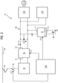
- FIG. 1 shows an exemplary embodiment of an arrangement 10, which can form part of a rail vehicle, in particular a rail vehicle, which is not shown in more detail for reasons of clarity.
- the arrangement 10 comprises a pantograph 20 or pantograph, which can be connected to a trackside contact wire or overhead line or a trackside conductor rail of a trackside, ie external, energy supply network 30 .
- the pantograph 20 is connected via a main switch 35 to a transformer 40 which is connected to a first connection side 51 of a converter 50 .
- a converter 50 is preferably a four-quadrant converter, which converts the alternating current of the energy supply network 30, which has been stepped down by the transformer 40, into a direct current with a voltage level that is as constant as possible for the direct voltage intermediate circuit.
- a second connection side 52 of the converter 50 is connected to a DC voltage intermediate circuit 60 .
- An intermediate circuit voltage Uz is present at the DC voltage intermediate circuit 60 .
- a DC voltage converter (DC/DC converter) 70 is also connected to the DC voltage intermediate circuit 60 with its first connection side 71 .
- a second connection side 72 of the DC voltage regulator 70 is connected to an energy store 80, for example a traction battery, as the arrangement's own energy supply device.
- converter 50 and DC voltage controller 70 can each be operated as a voltage source for DC voltage intermediate circuit 60, and during their voltage source operation they each try to set a predefined setpoint intermediate circuit voltage Usoll as the target voltage for DC voltage intermediate circuit 60.
- DC voltage intermediate circuit 60 is used to operate various components of the rail vehicle, for example to operate a pulse-controlled inverter 100 and a drive motor 110 connected to it and, for example, an auxiliary converter 120, which is connected to an on-board electrical system (not shown) of the rail vehicle and can feed it with energy.
- control device 200 which by means of a first control signal ST1 controls the converter 50 and controls the DC voltage controller 70 by means of a second control signal ST2.
- the control device 20 can initiate the opening and closing of the main switch 35 by means of a third control signal ST3.
- the control device 200 allows the following four operating modes: First operating mode of the arrangement 10: external energy supply operation when connected to the external energy supply network 30 ( figure 2 ).
- the DC link 60 is operated by the converter 50 as a voltage source.
- the control device 200 will use the first control signal ST1 to control the converter 50 in such a way that it sets the specified setpoint intermediate circuit voltage Usoll as the target voltage for the DC voltage intermediate circuit 60 .
- the DC voltage converter 70 is operated by the control device 200 using the second control signal ST2 as a charging device for the energy store 80 .
- the DC voltage controller 70 charges the energy storage device 80 by drawing energy from the DC voltage intermediate circuit 60 if the energy storage device 80 is not yet sufficiently charged, or leaves it disconnected from the DC voltage intermediate circuit 60 if the energy storage device 80 is sufficiently charged.
- the DC voltage controller 70 can compare the voltage Ub at the energy store 80 with a maximum storage voltage Umax and control the charging process according to the comparison result. If the maximum storage voltage Umax is less than the setpoint intermediate circuit voltage Usoll, then the DC voltage converter 70 operates in the charging mode, preferably in a current-controlled manner as a step-down converter.
- Second operating mode of the arrangement 10 energy storage operation without an external energy supply network 30 ( figure 3 ).
- the control device 200 will operate the DC voltage regulator 70 in its third operating mode, i.e. as a voltage source for the DC voltage intermediate circuit 60, specifically in such a way that the DC voltage controller 70 now attempts to generate the specified setpoint intermediate circuit voltage Usetpoint as the target voltage for the DC voltage intermediate circuit 60 .
- the converter 50 is preferably deactivated by means of the first control signal ST1, and the main switch 35 is also preferably opened by means of the third control signal ST3.
- DC voltage controller 70 As soon as DC voltage controller 70 is operating as a voltage source for DC voltage link 60, energy is fed from energy store 80 into DC voltage link 60 when the components connected to it, such as pulse-controlled inverter 100, drive motor 110, or auxiliary converter 120, require more energy from the DC voltage intermediate circuit 60 is removed than is fed. Otherwise, energy is taken from intermediate DC circuit 60 and fed into energy store 80, i.e. when the components mentioned feed energy in total or in total, for example when drive motor 110 feeds sufficient braking energy into intermediate DC circuit 60 during braking operation of the rail vehicle.
- Third operating mode of the arrangement 10 switching from the first operating mode to the second operating mode, ie from the external Energy supply mode in the energy storage mode ( Figure 4).
- the control device 200 will first switch to its third operating mode.
- the control device 200 will operate the converter 50 and the DC voltage controller 70 simultaneously or in parallel as a voltage source for the DC voltage intermediate circuit 60 .
- the control device 200 transmits target voltages of different levels to the converter 50 using the first control signal ST1 and to the DC voltage controller 70 using the second control signal ST2 specify for the DC link 60.
- the control device 200 specifies the setpoint intermediate circuit voltage Usoll as the target voltage for the DC voltage intermediate circuit 60 for the converter 50, whereas the DC voltage controller 70 specifies a smaller auxiliary voltage Uh.
- the auxiliary voltage Uh specified for the DC voltage controller 70 can only be 1,500 V.
- the auxiliary voltage Uh is preferably dimensioned so high that the components connected to the DC link 60, such as the pulse-controlled inverter 100, the drive motor 110 or the auxiliary converter 120, can continue to be operated with this voltage.
- the DC voltage controller 70 Since the DC voltage controller 70 is now switched from its first operating mode, in which it works as a charging device for the energy store 80, to its second operating mode, in which it works as a voltage source for generating the auxiliary voltage Uh, a certain delay in the Operation of the DC voltage controller 70 occur. In other words, the DC voltage controller 70 will not be able to switch abruptly from its first operating mode to its second operating mode. The control device 200 will monitor this delay in the transition from the first operating mode to the second operating mode by monitoring the current I1 flowing through the DC voltage converter 70 .
- the DC voltage controller 70 determines that it has reached a specified switching current value Is, it concludes that the DC voltage controller 70 has reached its second operating mode or is exercising it and - as desired - is attempting to use the auxiliary voltage Uh as the target voltage for the DC intermediate circuit 60 set. Since the auxiliary voltage Uh is less than the setpoint intermediate circuit voltage Usoll, when the DC voltage controller 70 is operated in its second operating mode, the DC voltage controller 70 conducts current from the DC voltage intermediate circuit 60 into the energy store 80, around the capacitor C of the DC voltage intermediate circuit 60 - outgoing from the setpoint intermediate circuit voltage Usoll set by the converter 50 and to lower the intermediate circuit voltage Uz to the value of the auxiliary voltage Uh.
- control device 200 As soon as the control device 200 has recognized that the current I1 through the DC voltage regulator 70 has reached the switching current value Is, it will deactivate the converter 50 so that the DC voltage intermediate circuit 60 is decoupled from the transformer 40 and from the main switch 35 . The control device 200 will then open the main switch 35, preferably by means of the third control signal ST3, in order to bring about a separation from the pantograph 20.
- the current I1 through the DC voltage converter 70 in the second operating mode and when switching over from the first operating mode to the second operating mode is limited by the control device 200 to a predetermined maximum current value in order to prevent damage to the DC voltage converter 70 and damage to the energy store 80 to avoid.
- the control device 200 can increase the target voltage for the DC voltage regulator 70 from the auxiliary voltage Uh to the setpoint intermediate circuit voltage Usoll, as a result of which the DC voltage regulator 70 is transferred to its third operating mode.
- Fourth operating mode of the arrangement 10 switching from the second operating mode to the first operating mode, ie from the energy storage mode to the external energy supply mode ( figure 5 ).
- a changeover from the energy supply mode to the converter mode preferably takes place as follows: First, the control device 200 will switch the DC voltage controller 70 from the third operating mode, in which it sets the target intermediate circuit voltage Usoll as the voltage source, to the second operating mode, in which the DC voltage controller 70 is to set a lower voltage as the target voltage, namely the auxiliary voltage Uh again . In other words, for the DC voltage controller 70, only the target voltage is lowered from the setpoint intermediate circuit voltage Usoll to the auxiliary voltage Uh.
- the converter 50 is activated. Since, after the converter 50 has been switched on, there is a certain switch-on delay before the converter is operating correctly will occur, the control device 200 will, for example, monitor the operation of the converter 50 after the converter 50 has been activated.
- the intermediate circuit voltage Uz is rising and exceeds the auxiliary voltage Uh, which is to be set by the DC voltage controller 70, then it concludes that the converter 50 has started its correct voltage source operation. As soon as the intermediate circuit voltage Uz corresponds to the specified setpoint intermediate circuit voltage Usetpoint, it will regard the converter 50 as being fully operational, so that the DC voltage controller 70 can be switched over from its second operating mode to its first operating mode, in which it works as a charging device.
- control device 200 can monitor the current I2 between the converter 50 and the DC link 60 and switch the DC voltage controller 70 to the first operating mode as soon as the current I2 flowing from the converter 50 into the DC link 60 exceeds a predetermined threshold value I2s .
- FIG. 1 shows an exemplary embodiment of an arrangement 10 in which the control device 200 has a converter control module 201 for controlling the converter 50 and a DC voltage converter module 202 for controlling the DC voltage converter 70. There is also a monitoring module 203, namely for monitoring the current I1 that flows into the DC voltage controller 70, for monitoring the current I2 that flows from the converter 50 into the DC voltage intermediate circuit 60, and/or for monitoring the intermediate circuit voltage Uz on the DC voltage intermediate circuit 60.
- control device 200 has a central module 204 which, on the basis of the monitoring results ERG from the monitoring module 203, controls the converter control module 201 and the DC voltage converter module 202 in such a way that converter 50 and DC voltage converter 70 operate in such a way like this above in connection with the Figures 1 to 5 has been explained. In this regard, the above explanations apply accordingly.
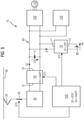
- the figure 7 shows an embodiment of an arrangement 10, in which the connection with the figure 6 shown modules of the control device 200 are arranged decentrally. It can thus be seen that the converter control module 201 is arranged in the converter 50 and the DC voltage converter module 202 in the DC voltage converter 70 or forms components of the converter 50 and the DC voltage converter 70 .
- the central module 204 and the monitoring module 203 are arranged separately.
Landscapes
- Engineering & Computer Science (AREA)
- Life Sciences & Earth Sciences (AREA)
- Sustainable Development (AREA)
- Sustainable Energy (AREA)
- Power Engineering (AREA)
- Transportation (AREA)
- Mechanical Engineering (AREA)
- Electric Propulsion And Braking For Vehicles (AREA)
- Dc-Dc Converters (AREA)
Applications Claiming Priority (1)
| Application Number | Priority Date | Filing Date | Title |
|---|---|---|---|
| DE102020211315.7A DE102020211315A1 (de) | 2020-09-09 | 2020-09-09 | Anordnung mit Umrichter und Gleichspannungssteller |
Publications (1)
| Publication Number | Publication Date |
|---|---|
| EP3967544A1 true EP3967544A1 (fr) | 2022-03-16 |
Family
ID=77627011
Family Applications (1)
| Application Number | Title | Priority Date | Filing Date |
|---|---|---|---|
| EP21194551.4A Pending EP3967544A1 (fr) | 2020-09-09 | 2021-09-02 | Agencement d'entraînement d'un véhicule ferroviaire |
Country Status (2)
| Country | Link |
|---|---|
| EP (1) | EP3967544A1 (fr) |
| DE (1) | DE102020211315A1 (fr) |
Cited By (1)
| Publication number | Priority date | Publication date | Assignee | Title |
|---|---|---|---|---|
| WO2024046734A1 (fr) * | 2022-08-30 | 2024-03-07 | Siemens Mobility GmbH | Agencement d'entraînement d'un véhicule ferroviaire |
Citations (2)
| Publication number | Priority date | Publication date | Assignee | Title |
|---|---|---|---|---|
| CN106042957A (zh) * | 2016-06-01 | 2016-10-26 | 北京交通大学 | 一种混合动力动车组牵引变流器过分相控制策略 |
| DE102018203015B3 (de) * | 2018-02-28 | 2019-05-09 | Siemens Aktiengesellschaft | Verfahren zur Regelung eines Batteriestroms einer Traktionsbatterie |
Family Cites Families (4)
| Publication number | Priority date | Publication date | Assignee | Title |
|---|---|---|---|---|
| JP3900822B2 (ja) | 2000-11-16 | 2007-04-04 | 株式会社豊田自動織機 | 非接触で給電される移動体の電源回路 |
| CA2657758C (fr) | 2006-08-09 | 2013-03-26 | Mitsubishi Electric Corporation | Convertisseur d'alimentation et controleur y faisant appel pour materiel roulant a moteur electrique |
| JP4958846B2 (ja) | 2008-06-03 | 2012-06-20 | 株式会社日立製作所 | 間歇受電を行う車両用制御装置 |
| DE102017213306A1 (de) | 2017-08-01 | 2019-02-07 | Siemens Aktiengesellschaft | Energieversorgungseinrichtung für ein Schienenfahrzeug |
-
2020
- 2020-09-09 DE DE102020211315.7A patent/DE102020211315A1/de active Pending
-
2021
- 2021-09-02 EP EP21194551.4A patent/EP3967544A1/fr active Pending
Patent Citations (2)
| Publication number | Priority date | Publication date | Assignee | Title |
|---|---|---|---|---|
| CN106042957A (zh) * | 2016-06-01 | 2016-10-26 | 北京交通大学 | 一种混合动力动车组牵引变流器过分相控制策略 |
| DE102018203015B3 (de) * | 2018-02-28 | 2019-05-09 | Siemens Aktiengesellschaft | Verfahren zur Regelung eines Batteriestroms einer Traktionsbatterie |
Cited By (1)
| Publication number | Priority date | Publication date | Assignee | Title |
|---|---|---|---|---|
| WO2024046734A1 (fr) * | 2022-08-30 | 2024-03-07 | Siemens Mobility GmbH | Agencement d'entraînement d'un véhicule ferroviaire |
Also Published As
| Publication number | Publication date |
|---|---|
| DE102020211315A1 (de) | 2022-03-10 |
Similar Documents
| Publication | Publication Date | Title |
|---|---|---|
| DE102011109709B4 (de) | Verfahren und System zur Spannungsversorgung eines Bordnetzes eines Fahrzeugs | |
| EP3137335B1 (fr) | Commande pour véhicule à entraînement électrique, véhicule à entraînement électrique comportant une commande et procédé | |
| DE102014006028B4 (de) | Multibatteriesystem zur Erhöhung der elektrischen Reichweite | |
| DE102015206259A1 (de) | Aktive isolierte schaltung zum vorladen und entladen eines hochspannungsbusses | |
| EP3634803B1 (fr) | Source de puissance pour un vehicule ferroviare | |
| EP3556594B1 (fr) | Procédé de fonctionnement d'un véhicule ainsi que véhicule | |
| DE112021002720T5 (de) | Leistungsversorgungssystem | |
| EP3544844A1 (fr) | Procédé permettant de faire fonctionner une batterie bi-tension | |
| DE102018131363A1 (de) | Verfahren zum Betrieb eines Hochvoltnetzes in einem Elektro- oder Hybridfahrzeug, Hochvoltnetz für ein Elektro- oder Hybridfahrzeug und Elektro- oder Hybridfahrzeug | |
| WO2014079603A2 (fr) | Ensemble circuit électrique pour un véhicule électrique, véhicule et procédé correspondant | |
| WO2018219643A1 (fr) | Circuit de décharge et procédé de décharge d'un circuit intermédiaire haute tension d'un véhicule | |
| EP3967544A1 (fr) | Agencement d'entraînement d'un véhicule ferroviaire | |
| DE102011118716A1 (de) | Speichersystem für elektrische Energie und Verfahren zum Entladen und Laden eines derartigen Speichersystems | |
| DE102018218312A1 (de) | Energieversorgungsanordnung zur Versorgung eines elektrischen Verbrauchers eines Niedervolt-Bordnetzes eines Kraftfahrzeugs, Bordnetz und Verfahren zum Betreiben einer Energieversorgungsanordnung | |
| DE102020204336B4 (de) | Fahrzeugseitige Hochvolt-Ladeschaltung und Fahrzeugbordnetz | |
| WO2020254470A1 (fr) | Ensemble circuit pour un véhicule à moteur et procédé pour adapter une tension d'un circuit intermédiaire à courant continu haute tension dans un véhicule à moteur | |
| WO2020020612A1 (fr) | Système d'énergie électrique comprenant des piles à combustible | |
| WO2018108495A1 (fr) | Système de machines électriques | |
| EP4371801A1 (fr) | Véhicule électrique et son procédé de fonctionnement | |
| WO2024068113A1 (fr) | Dispositif convertisseur cc-cc, système d'alimentation électrique et procédé de décharge d'un condensateur de liaison cc | |
| WO2004080747A1 (fr) | Systeme d'entrainement hybride et procede pour regler un systeme d'entrainement hybride | |
| DE102021116525A1 (de) | Vorrichtung und Verfahren zur elektrischen Versorgung eines Niederspannungs-Bordnetzes eines Kraftfahrzeugs, insbesondere Elektrokraftfahrzeugs | |
| WO2023036495A1 (fr) | Procédé et dispositif permettant de faire fonctionner un véhicule à propulsion électrique | |
| EP4344424A1 (fr) | Procédé et circuit de transfert d'énergie pour le transfert d'énergie électrique entre une batterie haute tension côté véhicule et un dispositif haute tension externe de véhicule | |
| DE102015012677A1 (de) | Verfahren und Vorrichtung zum Energiemanagement in einem Kraftfahrzeug mit mindestens zwei angetriebenen Fahrzeugachsen |
Legal Events
| Date | Code | Title | Description |
|---|---|---|---|
| PUAI | Public reference made under article 153(3) epc to a published international application that has entered the european phase |
Free format text: ORIGINAL CODE: 0009012 |
|
| STAA | Information on the status of an ep patent application or granted ep patent |
Free format text: STATUS: THE APPLICATION HAS BEEN PUBLISHED |
|
| AK | Designated contracting states |
Kind code of ref document: A1 Designated state(s): AL AT BE BG CH CY CZ DE DK EE ES FI FR GB GR HR HU IE IS IT LI LT LU LV MC MK MT NL NO PL PT RO RS SE SI SK SM TR |
|
| STAA | Information on the status of an ep patent application or granted ep patent |
Free format text: STATUS: REQUEST FOR EXAMINATION WAS MADE |
|
| 17P | Request for examination filed |
Effective date: 20220916 |
|
| RBV | Designated contracting states (corrected) |
Designated state(s): AL AT BE BG CH CY CZ DE DK EE ES FI FR GB GR HR HU IE IS IT LI LT LU LV MC MK MT NL NO PL PT RO RS SE SI SK SM TR |