EP3967503A1 - Label printer - Google Patents
Label printer Download PDFInfo
- Publication number
- EP3967503A1 EP3967503A1 EP20195723.0A EP20195723A EP3967503A1 EP 3967503 A1 EP3967503 A1 EP 3967503A1 EP 20195723 A EP20195723 A EP 20195723A EP 3967503 A1 EP3967503 A1 EP 3967503A1
- Authority
- EP
- European Patent Office
- Prior art keywords
- pressure roller
- label printer
- roller
- stripping element
- stripping
- Prior art date
- Legal status (The legal status is an assumption and is not a legal conclusion. Google has not performed a legal analysis and makes no representation as to the accuracy of the status listed.)
- Pending
Links
Images


Classifications
-
- B—PERFORMING OPERATIONS; TRANSPORTING
- B41—PRINTING; LINING MACHINES; TYPEWRITERS; STAMPS
- B41J—TYPEWRITERS; SELECTIVE PRINTING MECHANISMS, i.e. MECHANISMS PRINTING OTHERWISE THAN FROM A FORME; CORRECTION OF TYPOGRAPHICAL ERRORS
- B41J11/00—Devices or arrangements of selective printing mechanisms, e.g. ink-jet printers or thermal printers, for supporting or handling copy material in sheet or web form
- B41J11/66—Applications of cutting devices
- B41J11/70—Applications of cutting devices cutting perpendicular to the direction of paper feed
-
- B—PERFORMING OPERATIONS; TRANSPORTING
- B41—PRINTING; LINING MACHINES; TYPEWRITERS; STAMPS
- B41J—TYPEWRITERS; SELECTIVE PRINTING MECHANISMS, i.e. MECHANISMS PRINTING OTHERWISE THAN FROM A FORME; CORRECTION OF TYPOGRAPHICAL ERRORS
- B41J11/00—Devices or arrangements of selective printing mechanisms, e.g. ink-jet printers or thermal printers, for supporting or handling copy material in sheet or web form
- B41J11/02—Platens
- B41J11/04—Roller platens
-
- B—PERFORMING OPERATIONS; TRANSPORTING
- B41—PRINTING; LINING MACHINES; TYPEWRITERS; STAMPS
- B41J—TYPEWRITERS; SELECTIVE PRINTING MECHANISMS, i.e. MECHANISMS PRINTING OTHERWISE THAN FROM A FORME; CORRECTION OF TYPOGRAPHICAL ERRORS
- B41J3/00—Typewriters or selective printing or marking mechanisms characterised by the purpose for which they are constructed
- B41J3/407—Typewriters or selective printing or marking mechanisms characterised by the purpose for which they are constructed for marking on special material
- B41J3/4075—Tape printers; Label printers
-
- B—PERFORMING OPERATIONS; TRANSPORTING
- B65—CONVEYING; PACKING; STORING; HANDLING THIN OR FILAMENTARY MATERIAL
- B65C—LABELLING OR TAGGING MACHINES, APPARATUS, OR PROCESSES
- B65C11/00—Manually-controlled or manually-operable label dispensers, e.g. modified for the application of labels to articles
- B65C11/02—Manually-controlled or manually-operable label dispensers, e.g. modified for the application of labels to articles having printing equipment
- B65C11/0289—Manually-controlled or manually-operable label dispensers, e.g. modified for the application of labels to articles having printing equipment using electrical or electro-mechanical means
Definitions
- the invention relates to a label printer for printing self-adhesive, carrier-free endless tape labels with a print head and a driven print roller, the endless tape labels being able to be guided along a label web between the print head and the print roller, and a stripping element downstream of the print roller in the transport direction of the endless tape labels for stripping the labels from the print roller.
- Such a label printer is from the document DE 10 2009 014 992 A1 famous.
- the stripping element Seen in the direction of transport of the endless strip labels, the stripping element is arranged behind the pressure roller and immediately adjacent to the pressure roller.
- the stripping element is intended for stripping the self-adhesive, carrier-free endless strip labels, also known as linerless labels, from the printing roller or for ensuring that the labels do not stick to the printing roller with their adhesive-coated underside.
- the respective printed label is then cut off by means of a cutter, such as is found in the document, for example DE 199 58 274 A1 is known, or separated from the endless tape labels by a tear-off edge.
- the stripping element is required in particular when the respective next label has already partially passed through the printing area between the print head and the printing roller and the labels are also to be printed in the partial area that has already passed through.
- the endless band labels are then pulled back (reversing) at least approximately to the label beginning of the next label at which the previous label was severed, with the stripping element being able to prevent the beginning of the endless band from sticking to the pressure roller.
- the platen roller is a consumable part that may need to be replaced one or more times during the life of the label printer.
- replacing the print roller is time-consuming and can often only be carried out by a service technician.
- the invention is based on the object of specifying a label printer of the type mentioned at the outset, which enables the print roller to be replaced in a simple manner.
- a label printer having the features of independent claim 1, and in particular in that the print roller is inserted into a print roller mount of the label printer and is captively held in the print roll mount by the stripping element.
- the print roller is not installed in a complicated manner in the label printer, but it is only necessary to insert the print roller into a print roller receptacle and then to keep it captive in the inserted position by the stripping element that is present anyway.
- the pressure roller can then also be replaced by an untrained operator.
- the label printer comprises a cutter downstream of the stripping element in the transport direction of the endless strip labels for separating the endless strip labels, which cutter comprises a transport roller and a knife unit that can be moved linearly parallel to the axis of rotation of the transport roller, with the endless strip labels between the Transport roller and the knife unit can be passed through, and wherein the transport roller of the cutter is mounted on the stripping element.
- the transport roller serves as a counter-holder for a cutting knife of the knife unit.
- the stripping element can comprise an elongated stripping section, the longitudinal extent of which runs parallel to the axis of rotation of the pressure roller and which, at its two ends lying in the direction of the axis of rotation of the pressure roller, has a respective receiving section, in particular with a respective peripheral recess, for the both axial ends of the transport roller of the cutter.
- the transport roller can then simply be inserted into the two receiving sections, in particular the two recesses on the edge.
- the respective axial end of the transport roller is secured by a respective axially inserted bearing sleeve in the respective recess of the respective receiving section of the stripping element.
- the respective axial end of the transport roller is inserted into the respective recess of the respective receiving section of the stripping element, forming a respective snap connection.
- the transport roller can be mounted on the stripping element in a particularly simple manner.
- the label printer comprises a housing and a housing element attached to an open side of the housing and which can be folded between a closed position and an open position about a pivot axis, in particular a door, with the print head and in particular the aforementioned blade unit , mounted in the housing box, in particular, and the pressure roller and the scraper element, and in particular the aforesaid transport roller, are attached to the foldable housing element.
- the pressure roller with the hinged housing element is pivoted out of the housing box and is therefore particularly easily accessible for replacement.
- the printing roller when the hinged housing element is in the closed position, the printing roller can be firmly fixed in the label printer by a safety device which is arranged in the housing box and becomes effective when the hinged housing element is closed.
- a safety device which is arranged in the housing box and becomes effective when the hinged housing element is closed.
- the foldable housing element can comprise two opposite side walls, which are articulated with their respective first end to a respective side wall of the housing, which extend into the housing box in the closed position of the foldable housing element and on which, in particular at their respective second end, the pressure roller receptacle, in particular in the form of a respective marginal recess for the two axial ends of the pressure roller.
- the pressure roller can be easily inserted into the two edge recesses.
- the aforementioned safety device can comprise, for example, two stops which, at the end of the closing of the foldable housing element, press against the two axial ends of the pressure roller pivoting into the housing box.
- the pressure roller is preferably mounted indirectly via a bearing element, in particular a bearing sleeve, at each of its two axial ends in the pressure roller receptacle.
- the bearing surface for the two axial ends of the pressure roller can be increased by the two bearing elements.
- the technical Flexibility in the storage of the pressure roller can be increased.
- the respective bearing element can be subjected to a spring force, for example as explained below, without influencing the rotational movement of the pressure roller.
- the two side walls can be connected to one another via a cross brace.
- the stripping element is attached to the cross brace of the foldable housing element.
- the pressure roller can be removed from the pressure roller seat and inserted into the pressure roller seat at an angle in the range of 60° to 120° to the label web. In this angular range, the captive holding of the pressure roller in the pressure roller receptacle can be implemented particularly easily by the stripping element.
- the stripping element and the pressure roller can have an overlap in the range of 0.3 mm to 3 mm, preferably 0.3 mm to 2 mm, in a projection onto the label web.
- the direct or closest distance between the stripping element and the pressure roller can be in the range of 0.5 mm to 3 mm, for example.
- the diameter of the pressure roller can have a value in the range from 10 mm to 35 mm, for example.
- the pressure roller is made of an elastically deformable material, in particular silicone, and, with the application of a correspondingly large force, can be forced out of the pressure roller receptacle and into the pressure roller receptacle non-destructively, with the formation of an elastic deformation past the stripping element.
- the one required for this Effort can be adjusted via the aforementioned overlap.
- This construction is particularly inexpensive. No further holding means are required to hold the printing roller in the printing roller mount.
- the pressure roller in particular by means of a slot arrangement and/or transversely to a removal direction of the pressure roller, is between an operating position in which the pressure roller is held captively in the pressure roller receptacle by the stripping element and in which the pressure roller is prestressed by means of a spring device is, and a removal position in which the pressure roller can be removed without resistance by the stripping element from the pressure roller holder, slidably mounted.
- the stripping element is releasably fastened in the label printer, the pressure roller being removable by the stripping element from the pressure roller receptacle without resistance after the stripping element has been loosened, in particular unscrewed, in particular by means of a knurled screw.
- the pressure roller can preferably be removed from the pressure roller receptacle and inserted into the pressure roller receptacle without tools, in particular as is described in the above embodiments.
- the replacement of the pressure roller can thus be carried out particularly easily and conveniently.
- the invention also relates to scales, in particular retail scales, with a label printer as described above.
- the exemplary retail scale 11 shown comprises a load plate 13 which determines the weight of an article lying on it, which is displayed both on a display 15 for the customer and on a display 17 for the seller.
- the display 17 is designed as a touch screen, so that the retail scales 11 can also be operated via this.
- An identification number (PLU) assigned to the respective article can be entered via the touchscreen 17 so that, taking the weight into account, a price can be calculated for the article, which is then also displayed on the two displays 15 , 17 .
- the retail scale includes a label printer 19 for printing a label with the weight, the name of the item and the price charged.
- the label printer 19 has a housing 21 which is open towards the front, this open side of the housing 21 being closable by a housing element 23 which is attached to the housing 21 and can be folded about a pivot axis D, with in 1 the closed position and thus the operating position of the hinged housing element 23 is shown.
- the label printer 19 is operated with self-adhesive, carrier-free endless tape labels.
- inside the label printer 19 there is a holder (not shown in the figures) for a corresponding label roll, on which the endless strip labels are wound, the label roll being able to be inserted into the holder when the hinged housing element 23 is in the open position.
- the Endless labels are guided in the label printer 19 along a predetermined transport path. After each label has been printed, it is separated from the endless belt and output at a label output 25 of the label printer 19 .
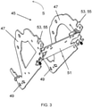
- the 2 shows the label printer 19 in the area of label output 25, with a front cover plate 27 of the foldable housing element 23 and a front cover section 29 of the housing box 21 (cf. 1 ) have been omitted so that the interior of the label printer 19 can be seen in this area.
- the label printer 19 has a cutter 31 with which the labels can be separated from the endless belt.
- the cutter 31 is seen in the direction of transport of the endless tape labels a print head 41, which is only in 6 and is shown only schematically there, and a pressure roller 43 driven about an axis of rotation T (cf Figures 4-6 , 9 and 10 ) of the label printer 19, between which the endless tape labels are passed, downstream.
- the print head 41 and the platen roller 43 are in 2 arranged behind or below the cutter 31 and thus in 2 not visible.
- the cutter 31 comprises according to 2 a driven transport roller 33, rotatable about an axis of rotation R, for the endless band labels. Furthermore, a knife unit 35 is provided, which can be moved linearly parallel to the axis of rotation R of the transport roller 33 .
- the blade unit 35 is designed as a spindle nut which is driven by an electric motor 39 to be movable in both axial directions of the threaded rod 37 via a threaded rod 37 with which it forms a threaded spindle.
- the self-adhesive tape labels without a carrier are guided between the transport roller 33 and the cutter unit 35, with the transport roller 33 acting as a counter-holder for the cutter unit 35.
- the blade unit 35 is shown only schematically.
- the label printer 19 is constructed in such a way that the print head 41 and the cutter unit 35 are mounted in the housing case 21, and that the pressure roller 43 and the transport roller 33 are mounted on the foldable housing element 23, as can be seen in particular from FIGS figure 5 and 6 can be seen, in which a frame construction 45 of the foldable housing element 23 (cf. 3 ) is shown together with the pressure roller 43 and the transport roller 33, each of which is supported on the frame structure 45.
- the pressure roller 43 and the transport roller 33 are thus pivoted into the housing case 21 when the hinged housing element 23 is closed (cf. the closing direction S in 3 ) and thus only assume their operating position when the hinged housing element 23 is in the closed position.
- the frame structure 45 of the foldable housing element 23 comprises according to 3 two opposite side panels 47 which are each articulated at one end to a side wall of the housing case 21 , the two articulation points 49 forming the pivot axis D of the foldable housing element 23 .
- the two side walls 47 extend into the housing box 21 when the housing element 23 is in the closed position.
- the frame structure 45 includes a cross brace 51 which connects the two side panels 47 to one another.
- the two side walls 47 have a respective peripheral recess 53, into which the two axial ends of the pressure roller 43 are inserted, as in particular in 4 is shown.
- the two edge recesses 53 thus together form a receptacle 55 for the pressure roller 43.
- the two axial ends of the pressure roller 43 are inserted indirectly into the two edge recesses 53 via a respective bearing element 57 in the form of a bearing sleeve, as can be seen from 9 results.
- a stripping element 61 is provided which, seen in the transport direction of the endless strip labels, is located immediately downstream of the pressure roller 43 and immediately upstream of the cutter 31, i.e. it is arranged between the pressure roller 43 and the transport roller 33 of the cutter 31, as in particular in FIGS figure 5 and 6 is shown.
- the stripping element 61 is used to strip the self-adhesive, carrier-less endless strip labels from the pressure roller 43 or to prevent the beginning of the endless strip from sticking to the pressure roller 43, in particular after a label has been separated and, if necessary, a possible reversal of the endless strip labels.
- the stripping element 61 is also attached to the foldable housing element 23 and is pivoted into the housing box 21 when the foldable housing element 23 is closed. Specifically, the stripping element 61 is attached to the outside of the cross brace 51 of the frame construction 45 of the foldable housing element 23 by means of two screws 59, viewed in the closing direction S of the foldable housing element 23 (cf 2 and 6 ).
- the stripping element 61 also serves as a holder and bearing for the transport roller 33 of the cutter 31 (cf. 7 ).
- the stripping element 61 in addition to an elongated stripping section 63, the longitudinal extension of which is oriented parallel to the axis of rotation T of the pressure roller 43 and which fulfills the aforementioned stripping function, the stripping element 61 also has two receiving sections 65 for the transport roller 33 of the cutter 31.
- the two receiving sections 65 each have a peripheral recess 67 into which the two axial ends of the transport roller 33 are inserted (cf. 8 ).
- the two recesses 67 are delimited by two respective legs 69 into which the two axial ends of the transport roller 33 are inserted. Then the inserted into the two recesses 67 axial ends of the transport roller 33 by a respective not shown, axially insertable bearing sleeve secured in the receiving sections 65.
- the stripping element 61 is arranged so close to the pressure roller 43 and the removal direction of the pressure roller 43 from the pressure roller receptacle 55 is oriented such that the pressure roller 43 is captively held in the pressure roller receptacle 55 by the stripping element 61.
- the stripping element 61 seen in a projection onto the label web 73—has an overlap d of 0.3 mm to 3 mm with the pressure roller 43 (cf. 6 ) and the removal direction of the pressure roller 43 from the pressure roller receptacle 55 is oriented at about 70° to the label web 73.
- the pressure roller 43 can nevertheless easily be removed from the pressure roller mount 55 and replaced.
- the pressure roller 43 is made of an elastically deformable material such as silicone and can therefore be forced out of the pressure roller receptacle 55 past the stripping element 61 .
- the pressure roller 43 deforms elastically and thus non-destructively.
- the new pressure roller 43 can be forced into the pressure roller mount 55 .
- the pressure roller 43 can therefore be replaced without tools.
- the stripping element 61 it is also possible for the stripping element 61 to be unscrewed from the cross brace 51 first and then the pressure roller 43—without being held by the stripping element 61—to be removed from the pressure roller receptacle 55 .
- a further embodiment of the invention in which the pressure roller 43 via bearing elements 57, in particular bearing sleeves, in a pressure roller receptacle 55, in particular peripheral recesses 53, of the side walls 47 of the foldable housing element 23 is mounted.
- the two bearing elements 57 there is a slot 71 running perpendicularly to the removal direction of the pressure roller 43, in which the two axial ends of the pressure roller 43 can be displaced between the operating position shown and a removal position.
- the pressure roller 43 In the operating position, in which the pressure roller 43 is prestressed by means of a spring device (not shown), the pressure roller 43 is 10 not shown stripping element 61 held captive in the pressure roller receptacle 55.
- the removal position the pressure roller 43 can be removed from the pressure roller receptacle 55 past the stripping element 61 without coming into contact with the stripping element 61 .
Abstract
Die Erfindung betrifft einen Etikettendrucker zum Bedrucken von selbstklebenden trägerlosen Endlosband-Etiketten mit einem Druckkopf (41) und einer angetriebenen Druckwalze (43), wobei die Endlosband-Etiketten entlang einer Etikettenbahn (73) zwischen dem Druckkopf und der Druckwalze hindurchführbar sind, und einem der Druckwalze in Transportrichtung der Endlosband-Etiketten nachgeschalteten Abstreifelement (61) zum Abstreifen der Etiketten von der Druckwalze, wobei die Druckwalze (43) in eine Druckwalzenaufnahme (55) des Etikettendruckers (19) austauschbar eingesetzt ist und durch das Abstreifelement (61) verliersicher in der Druckwalzenaufnahme (55) gehalten ist.The invention relates to a label printer for printing self-adhesive, carrier-free endless tape labels, having a print head (41) and a driven print roller (43), the endless tape labels being able to be guided along a label web (73) between the print head and the print roller, and one of the Pressure roller in the direction of transport of the endless strip labels downstream stripping element (61) for stripping the labels from the pressure roller, the pressure roller (43) being replaceably inserted into a pressure roller mount (55) of the label printer (19) and captively secured by the stripping element (61) in the Pressure roller mount (55) is held.
Description
Die Erfindung betrifft einen Etikettendrucker zum Bedrucken von selbstklebenden trägerlosen Endlosband-Etiketten mit einem Druckkopf und einer angetriebenen Druckwalze, wobei die Endlosband-Etiketten entlang einer Etikettenbahn zwischen dem Druckkopf und der Druckwalze hindurchführbar sind, und einem der Druckwalze in Transportrichtung der Endlosband-Etiketten nachgeschalteten Abstreifelement zum Abstreifen der Etiketten von der Druckwalze.The invention relates to a label printer for printing self-adhesive, carrier-free endless tape labels with a print head and a driven print roller, the endless tape labels being able to be guided along a label web between the print head and the print roller, and a stripping element downstream of the print roller in the transport direction of the endless tape labels for stripping the labels from the print roller.
Ein derartiger Etikettendrucker ist aus dem Dokument
Bei der Druckwalze handelt es sich um ein Verschleißteil, das während der Lebensdauer des Etikettendruckers unter Umständen ein- oder mehrfach ausgetauscht werden muss. Der Austausch der Druckwalze ist jedoch aufwändig und kann oft nur durch einen Service-Techniker vorgenommen werden.The platen roller is a consumable part that may need to be replaced one or more times during the life of the label printer. However, replacing the print roller is time-consuming and can often only be carried out by a service technician.
Der Erfindung liegt die Aufgabe zugrunde, einen Etikettendrucker der eingangs genannten Art anzugeben, der einen einfachen Austausch der Druckwalze ermöglicht.The invention is based on the object of specifying a label printer of the type mentioned at the outset, which enables the print roller to be replaced in a simple manner.
Diese Aufgabe wird durch einen Etikettendrucker mit den Merkmalen des unabhängigen Anspruchs 1 gelöst, und insbesondere dadurch, dass die Druckwalze in eine Druckwalzenaufnahme des Etikettendruckers eingesetzt ist und durch das Abstreifelement verliersicher in der Druckwalzenaufnahme gehalten ist.This object is achieved by a label printer having the features of independent claim 1, and in particular in that the print roller is inserted into a print roller mount of the label printer and is captively held in the print roll mount by the stripping element.
Erfindungsgemäß ist die Druckwalze also nicht kompliziert in dem Etikettendrucker verbaut, sondern es ist lediglich erforderlich, die Druckwalze in eine Druckwalzenaufnahme einzusetzen und durch das ohnehin vorhandene Abstreifelement dann in der eingesetzten Position verliersicher zu halten. Der Austausch der Druckwalze kann dann auch durch einen ungeschulten Bediener erfolgen.According to the invention, the print roller is not installed in a complicated manner in the label printer, but it is only necessary to insert the print roller into a print roller receptacle and then to keep it captive in the inserted position by the stripping element that is present anyway. The pressure roller can then also be replaced by an untrained operator.
Nach einer bevorzugten Ausbildung der Erfindung umfasst der Etikettendrucker einen dem Abstreifelement in Transportrichtung der Endlosband-Etiketten nachgeschalteten Abschneider zum Vereinzeln der Endlosband-Etiketten, der eine Transportrolle und eine parallel zu der Drehachse der Transportrolle linear verfahrbare Messereinheit umfasst, wobei die Endlosband-Etiketten zwischen der Transportrolle und der Messereinheit hindurchführbar sind, und wobei die Transportrolle des Abschneiders an dem Abstreifelement gelagert ist. Die Transportrolle dient dabei als Gegenhalter für ein Schneidmesser der Messereinheit. Durch die Lagerung der Transportrolle des Abschneiders direkt an dem Abstreifelement kann eine kompakte Ausbildung erreicht werden. Insbesondere kann der Abstand zwischen der Druckwalze und der Transportrolle des Abschneiders gering gehalten werden, so dass ein etwaiges Reversieren der Endlosband-Etiketten auf ein Minimum begrenzt, unter Umständen vollständig vermieden, werden kann, wodurch die Druckgeschwindigkeit des Etikettendruckers erhöht werden kann.According to a preferred embodiment of the invention, the label printer comprises a cutter downstream of the stripping element in the transport direction of the endless strip labels for separating the endless strip labels, which cutter comprises a transport roller and a knife unit that can be moved linearly parallel to the axis of rotation of the transport roller, with the endless strip labels between the Transport roller and the knife unit can be passed through, and wherein the transport roller of the cutter is mounted on the stripping element. The transport roller serves as a counter-holder for a cutting knife of the knife unit. By mounting the transport roller of the cutter directly on the stripping element a compact training can be achieved. In particular, the distance between the pressure roller and the transport roller of the cutter can be kept small, so that any reversing of the endless tape labels can be limited to a minimum, or even completely avoided, whereby the printing speed of the label printer can be increased.
Zur Lagerung des Abschneiders an dem Abstreifelement kann das Abstreifelement einen langgestreckten Abstreifabschnitt umfassen, dessen Längserstreckung parallel zu der Drehachse der Druckwalze verläuft und der an seinen beiden in Richtung der Drehachse der Druckwalze liegenden Enden einen jeweiligen Aufnahmeabschnitt, insbesondere mit einer jeweiligen randseitigen Ausnehmung, für die beiden axialen Enden der Transportrolle des Abschneiders aufweist. Die Transportrolle kann dann einfach in die beiden Aufnahmeabschnitte, insbesondere die beiden randseitigen Ausnehmungen, eingesetzt werden.To mount the cutter on the stripping element, the stripping element can comprise an elongated stripping section, the longitudinal extent of which runs parallel to the axis of rotation of the pressure roller and which, at its two ends lying in the direction of the axis of rotation of the pressure roller, has a respective receiving section, in particular with a respective peripheral recess, for the both axial ends of the transport roller of the cutter. The transport roller can then simply be inserted into the two receiving sections, in particular the two recesses on the edge.
Dabei kann vorgesehen sein, dass das jeweilige axiale Ende der Transportrolle durch eine jeweilige axial eingesetzte Lagerhülse in der jeweiligen Ausnehmung des jeweiligen Aufnahmeabschnitts des Abstreifelements gesichert ist. Alternativ kann auch vorgesehen sein, dass das jeweilige axiale Ende der Transportrolle unter Ausbildung einer jeweiligen Schnappverbindung in die jeweilige Ausnehmung des jeweiligen Aufnahmeabschnitts des Abstreifelements eingesetzt ist. In beiden Fällen kann die Transportrolle auf besonders einfache Weise an dem Abstreifelement gelagert werden.It can be provided that the respective axial end of the transport roller is secured by a respective axially inserted bearing sleeve in the respective recess of the respective receiving section of the stripping element. Alternatively, it can also be provided that the respective axial end of the transport roller is inserted into the respective recess of the respective receiving section of the stripping element, forming a respective snap connection. In both cases, the transport roller can be mounted on the stripping element in a particularly simple manner.
Nach einer bevorzugten Ausbildung der Erfindung umfasst der Etikettendrucker einen Gehäusekasten und ein an einer offenen Seite des Gehäusekastens angebrachtes, zwischen einer Geschlossen-Stellung und einer Offen-Stellung um eine Schwenkachse klappbares Gehäuseelement, insbesondere eine Tür, wobei der Druckkopf, und insbesondere die vorgenannte Messereinheit, in dem Gehäusekasten angebracht ist, insbesondere sind, und die Druckwalze und das Abstreifelement, und insbesondere die vorgenannte Transportrolle, an dem klappbaren Gehäuseelement angebracht sind. In der Offen-Stellung ist die Druckwalze mit dem klappbaren Gehäuseelement aus dem Gehäusekasten herausgeschwenkt und damit für einen Austausch besonders gut zugänglich.According to a preferred embodiment of the invention, the label printer comprises a housing and a housing element attached to an open side of the housing and which can be folded between a closed position and an open position about a pivot axis, in particular a door, with the print head and in particular the aforementioned blade unit , mounted in the housing box, in particular, and the pressure roller and the scraper element, and in particular the aforesaid transport roller, are attached to the foldable housing element. In the open position, the pressure roller with the hinged housing element is pivoted out of the housing box and is therefore particularly easily accessible for replacement.
Insbesondere kann die Druckwalze in der Geschlossen-Stellung des klappbaren Gehäuseelements durch eine in dem Gehäusekasten angeordnete Sicherungseinrichtung fest in dem Etikettendrucker fixiert werden, die beim Schließen des klappbaren Gehäuseelements wirksam wird. Dies ist insbesondere dann vorteilhaft, wenn die verliersichere Halterung der Druckwalze in der Druckwalzenaufnahme durch das Abstreifelement spielbehaftet ist.In particular, when the hinged housing element is in the closed position, the printing roller can be firmly fixed in the label printer by a safety device which is arranged in the housing box and becomes effective when the hinged housing element is closed. This is particularly advantageous when the captive mounting of the pressure roller in the pressure roller receptacle is subject to play due to the stripping element.
Insbesondere kann das klappbare Gehäuseelement zwei einander gegenüberliegende, mit ihrem jeweiligen ersten Ende an einer jeweiligen Seitenwand des Gehäuses angelenkte Seitenwangen umfassen, die sich in der Geschlossen-Stellung des klappbaren Gehäuseelements in den Gehäusekasten hinein erstrecken und an denen, insbesondere an ihrem jeweiligen zweiten Ende, die Druckwalzenaufnahme, insbesondere in Form einer jeweiligen randseitigen Ausnehmung für die beiden axialen Enden der Druckwalze ausgebildet ist. Hierdurch kann eine einfache und stabile Lagerung der Druckwalze erreicht werden. Insbesondere kann die Druckwalze einfach in die beiden randseitigen Ausnehmungen eingesetzt werden. Die vorgenannte Sicherungseinrichtung kann in diesem Fall beispielsweise zwei Anschläge umfassen, die am Ende des Schließens des klappbaren Gehäuseelements gegen die beiden axialen Enden der in den Gehäusekasten einschwenkenden Druckwalze drücken.In particular, the foldable housing element can comprise two opposite side walls, which are articulated with their respective first end to a respective side wall of the housing, which extend into the housing box in the closed position of the foldable housing element and on which, in particular at their respective second end, the pressure roller receptacle, in particular in the form of a respective marginal recess for the two axial ends of the pressure roller. In this way, a simple and stable mounting of the pressure roller can be achieved. In particular, the pressure roller can be easily inserted into the two edge recesses. In this case, the aforementioned safety device can comprise, for example, two stops which, at the end of the closing of the foldable housing element, press against the two axial ends of the pressure roller pivoting into the housing box.
Vorzugsweise ist die Druckwalze mittelbar über ein Lagerelement, insbesondere eine Lagerhülse, an jedem ihrer beiden axialen Enden in der Druckwalzenaufnahme gelagert. Durch die beiden Lagerelemente kann die Lagerfläche für die beiden axialen Enden der Druckwalze erhöht werden. Ferner kann die technische Flexibilität bei der Lagerung der Druckwalze erhöht werden. Beispielsweise kann das jeweilige Lagerelement mit einer Federkraft beaufschlagt werden, z.B. wie es nachfolgend erläutert ist, ohne dabei die Drehbewegung der Druckwalze zu beeinflussen.The pressure roller is preferably mounted indirectly via a bearing element, in particular a bearing sleeve, at each of its two axial ends in the pressure roller receptacle. The bearing surface for the two axial ends of the pressure roller can be increased by the two bearing elements. Furthermore, the technical Flexibility in the storage of the pressure roller can be increased. For example, the respective bearing element can be subjected to a spring force, for example as explained below, without influencing the rotational movement of the pressure roller.
Die beiden Seitenwangen können über eine Querstrebe miteinander verbunden sein. Dabei ist es bevorzugt, wenn das Abstreifelement an der Querstrebe des klappbaren Gehäuseelements angebracht ist. Hierdurch wird eine besonders einfache und gleichzeitig besonders stabile Konstruktion erreicht.The two side walls can be connected to one another via a cross brace. In this case, it is preferred if the stripping element is attached to the cross brace of the foldable housing element. As a result, a particularly simple and at the same time particularly stable construction is achieved.
Insbesondere kann die Druckwalze unter einem Winkel im Bereich von 60° bis 120° zu der Etikettenbahn aus der Druckwalzenaufnahme entnehmbar und in die Druckwalzenaufnahme einsetzbar sein. In diesem Winkelbereich kann die verliersichere Halterung der Druckwalze in der Druckwalzenaufnahme durch das Abstreifelement besonders einfach realisiert werden.In particular, the pressure roller can be removed from the pressure roller seat and inserted into the pressure roller seat at an angle in the range of 60° to 120° to the label web. In this angular range, the captive holding of the pressure roller in the pressure roller receptacle can be implemented particularly easily by the stripping element.
Das Abstreifelement und die Druckwalze können in einer Projektion auf die Etikettenbahn einen Überlapp im Bereich von 0,3 mm bis 3 mm, bevorzugt 0,3 mm bis 2 mm, aufweisen. Hierdurch kann die Abstreiffunktion des Abstreifelements auch bei dem vorgenannten Reversieren der Endlosband-Etiketten jederzeit gewährleistet werden. Der direkte bzw. näheste Abstand zwischen dem Abstreifelement und der Druckwalze kann beispielsweise im Bereich von 0,5 mm bis 3 mm liegen. Der Durchmesser der Druckwalze kann einen Wert beispielsweise im Bereich von 10 mm bis 35 mm betragen.The stripping element and the pressure roller can have an overlap in the range of 0.3 mm to 3 mm, preferably 0.3 mm to 2 mm, in a projection onto the label web. As a result, the stripping function of the stripping element can be guaranteed at all times, even during the aforementioned reversing of the endless strip labels. The direct or closest distance between the stripping element and the pressure roller can be in the range of 0.5 mm to 3 mm, for example. The diameter of the pressure roller can have a value in the range from 10 mm to 35 mm, for example.
Gemäß einer Ausführungsform der Erfindung ist die Druckwalze aus einem elastisch verformbaren Material, insbesondere Silikon, gefertigt und, bei entsprechend großer Krafteinwirkung, unter Ausbildung einer elastischen Verformung zerstörungsfrei an dem Abstreifelement vorbei aus der Druckwalzenaufnahme herauszwängbar und in die Druckwalzenaufnahme hineinzwängbar. Der hierfür erforderliche Kraftaufwand kann über den vorgenannten Überlapp eingestellt werden. Diese Konstruktion ist besonders kostengünstig. Es sind keine weiteren Haltemittel erforderlich, um die Druckwalze in der Druckwalzenaufnahme zu halten.According to one embodiment of the invention, the pressure roller is made of an elastically deformable material, in particular silicone, and, with the application of a correspondingly large force, can be forced out of the pressure roller receptacle and into the pressure roller receptacle non-destructively, with the formation of an elastic deformation past the stripping element. The one required for this Effort can be adjusted via the aforementioned overlap. This construction is particularly inexpensive. No further holding means are required to hold the printing roller in the printing roller mount.
Gemäß einer weiteren Ausführungsform der Erfindung ist die Druckwalze, insbesondere mittels einer Langlochanordnung und/oder quer zu einer Entnahmerichtung der Druckwalze, zwischen einer Betriebsposition, in der die Druckwalze durch das Abstreifelement verliersicher in der Druckwalzenaufnahme gehalten ist und in die die Druckwalze mittels einer Federeinrichtung vorgespannt ist, und einer Entnahmeposition, in der die Druckwalze ohne Widerstand durch das Abstreifelement aus der Druckwalzenaufnahme entnehmbar ist, verschiebbar gelagert. Bei dieser Konstruktion ist zur Überwindung der Vorspannung der Federeinrichtung, um die Druckwalze in die Entnahmeposition zu verschieben, lediglich ein geringer Kraftaufwand erforderlich.According to a further embodiment of the invention, the pressure roller, in particular by means of a slot arrangement and/or transversely to a removal direction of the pressure roller, is between an operating position in which the pressure roller is held captively in the pressure roller receptacle by the stripping element and in which the pressure roller is prestressed by means of a spring device is, and a removal position in which the pressure roller can be removed without resistance by the stripping element from the pressure roller holder, slidably mounted. With this construction, only a small amount of force is required to overcome the prestressing of the spring device in order to move the pressure roller into the removal position.
Gemäß einer anderen Ausführungsform der Erfindung ist das Abstreifelement lösbar in dem Etikettendrucker befestigt, wobei die Druckwalze nach Lösen, insbesondere Abschrauben, insbesondere mittels einer Rändelschraube, des Abstreifelements ohne Widerstand durch das Abstreifelement aus der Druckwalzenaufnahme entnehmbar ist. Diese Konstruktion ist für den Bediener zwar aufwändiger, aber intuitiv.According to another embodiment of the invention, the stripping element is releasably fastened in the label printer, the pressure roller being removable by the stripping element from the pressure roller receptacle without resistance after the stripping element has been loosened, in particular unscrewed, in particular by means of a knurled screw. Although this construction is more complex for the operator, it is intuitive.
Vorzugsweise ist die Druckwalze werkzeuglos aus der Druckwalzenaufnahme entnehmbar und in die Druckwalzenaufnahme einsetzbar, insbesondere wie es bei den vorstehenden Ausführungsformen beschrieben ist. Das Austauschen der Druckwalze kann damit besonders einfach und komfortabel erfolgen.The pressure roller can preferably be removed from the pressure roller receptacle and inserted into the pressure roller receptacle without tools, in particular as is described in the above embodiments. The replacement of the pressure roller can thus be carried out particularly easily and conveniently.
Die Erfindung betrifft ferner eine Waage, insbesondere Ladenwaage, mit einem Etikettendrucker, wie er vorstehend beschrieben ist.The invention also relates to scales, in particular retail scales, with a label printer as described above.
Weitere vorteilhafte Ausgestaltungen der Erfindung sind in den abhängigen Ansprüchen, der Figurenbeschreibung und der Zeichnung beschrieben.Further advantageous configurations of the invention are described in the dependent claims, the description of the figures and the drawing.
Die Erfindung wird nachfolgend beispielhaft unter Bezugnahme auf die Zeichnung beschrieben. Es zeigen,
- Fig. 1
- eine erfindungsgemäße Waage, insbesondere Ladenwaage, mit einem erfindungsgemäßen Etikettendrucker mit einem Gehäusekasten, der durch ein klappbares Gehäuseelement verschlossen ist,
- Fig. 2
- den Etikettendrucker gemäß
Fig. 1 in einer Vorderansicht im Bereich einer Etikettenausgabe, wobei eine vorderseitige Abdeckplatte des klappbaren Gehäuseelements und ein vorderseitiger Abdeckabschnitt des Gehäusekastens weggelassen sind, - Fig. 3
- eine perspektivische Ansicht einer Rahmenkonstruktion des klappbaren Gehäuseelements mit zwei Seitenwangen und einer Querstrebe gemäß einer Ausführungsform der Erfindung,
- Fig. 4
- die Rahmenkonstruktion gemäß
Fig. 3 mit einer Druckwalze, - Fig. 5
- die Rahmenkonstruktion gemäß
Fig. 4 mit der Druckwalze, einem Abstreifelement und einer Transportrolle eines Abschneiders, - Fig. 6
- die Rahmenkonstruktion gemäß
Fig. 5 mit der Druckwalze, dem Abstreif-element und der Transportrolle in einer Ansicht aus der Richtung A gemäßFig. 5 , wobei eine der beiden Seitenwangen weggelassen ist, - Fig. 7
- das Abstreifelement und die Transportrolle aus
Fig. 6 in einer Einzeldarstellung, - Fig. 8
- das Abstreifelement aus
Fig. 7 in einer Einzeldarstellung, - Fig. 9
- eine Darstellung der Lagerung der Druckwalze gemäß
Fig. 4 in einer der beiden Seitenwangen, und - Fig. 10
- eine weitere Ausführungsform der Erfindung.
- 1
- a scale according to the invention, in particular retail scales, with a label printer according to the invention with a housing box which is closed by a hinged housing element,
- 2
- according to the label printer
1 in a front view in the area of a label output, wherein a front cover plate of the foldable housing element and a front cover section of the housing case are omitted, - 3
- a perspective view of a frame construction of the foldable housing element with two side walls and a cross brace according to an embodiment of the invention,
- 4
- according to the frame construction
3 with a pressure roller, - figure 5
- according to the frame construction
4 with the pressure roller, a stripping element and a transport roller of a cutter, - 6
- according to the frame construction
figure 5 with the pressure roller, the scraper element and the transport roller in a view from direction A according tofigure 5 , where one of the two side panels is omitted, - 7
- the stripping element and the transport roller
6 in a single representation, - 8
- the stripping element
7 in a single representation, - 9
- a representation of the storage of the pressure roller according to FIG
4 in one of the two side panels, and - 10
- another embodiment of the invention.
Die in
Der Etikettendrucker 19 weist einen Gehäusekasten 21 auf, der nach vorne offen ist, wobei diese offene Seite des Gehäusekastens 21 durch ein an dem Gehäusekasten 21 angebrachtes, um eine Schwenkachse D klappbares Gehäuseelement 23 verschließbar ist, wobei in
Die
Der Abschneider 31 umfasst gemäß
Der Etikettendrucker 19 ist dabei derart aufgebaut, dass der Druckkopf 41 und die Messereinheit 35 in dem Gehäusekasten 21 angebracht sind, und dass die Druckwalze 43 und die Transportrolle 33 an dem klappbaren Gehäuseelement 23 angebracht sind, wie insbesondere aus den
Die Rahmenkonstruktion 45 des klappbaren Gehäuseelements 23 umfasst gemäß
An ihren zweiten Enden weisen die beiden Seitenwangen 47 eine jeweilige randseitige Ausnehmung 53 auf, in die die beiden axialen Enden der Druckwalze 43 eingesetzt sind, wie insbesondere in
Darüber hinaus ist ein Abstreifelement 61 vorgesehen, das in Transportrichtung der Endlosband-Etiketten gesehen der Druckwalze 43 unmittelbar nachgeschaltet und dem Abschneider 31 unmittelbar vorgeschaltet ist, d.h. zwischen der Druckwalze 43 und der Transportrolle 33 des Abschneiders 31 angeordnet ist, wie insbesondere in den
Das Abstreifelement 61 ist ebenfalls an dem klappbaren Gehäuseelement 23 angebracht und wird beim Schließen des klappbaren Gehäuseelements 23 in den Gehäusekasten 21 hineingeschwenkt. Konkret ist das Abstreifelement 61 über zwei Schrauben 59 in Schließrichtung S des klappbaren Gehäuseelements 23 gesehen außen an der Querstrebe 51 der Rahmenkonstruktion 45 des klappbaren Gehäuseelements 23 angebracht (vgl. die
Das Abstreifelement 61 dient dabei auch als Halterung und Lagerung der Transportrolle 33 des Abschneiders 31 (vgl.
Darüber hinaus ist das Abstreifelement 61 derart nahe an der Druckwalze 43 angeordnet und ist die Entnahmerichtung der Druckwalze 43 aus der Druckwalzenaufnahme 55 derart orientiert, dass die Druckwalze 43 durch das Abstreifelement 61 verliersicher in der Druckwalzenaufnahme 55 gehalten ist. Hierbei sind viele geometrisch voneinander verschiedene Varianten denkbar. Beispielsweise und bevorzugt besitzt das Abstreifelement 61 - in einer Projektion auf die Etikettenbahn 73 gesehen - mit der Druckwalze 43 einen Überlapp d von 0,3 mm bis 3 mm (vgl.
Trotz der verliersicheren Halterung kann die Druckwalze 43 gleichwohl ohne weiteres aus der Druckwalzenaufnahme 55 entnommen und ausgetauscht werden. Hierzu ist die Druckwalze 43 aus einem elastisch verformbaren Material wie Silikon gefertigt und kann deshalb an dem Abstreifelement 61 vorbei aus der Druckwalzenaufnahme 55 herausgezwängt werden. Hierbei verformt sich die Druckwalze 43 elastisch und damit zerstörungsfrei. Analog kann die neue Druckwalze 43 in die Druckwalzenaufnahme 55 hineingezwängt werden. Der Austausch der Druckwalze 43 kann daher werkzeuglos erfolgen.Despite the captive mounting, the
Natürlich ist es auch möglich, dass zunächst das Abstreifelement 61 von der Querstrebe 51 abgeschraubt wird und anschließend die Druckwalze 43 - ohne noch von dem Abstreifelement 61 gehalten zu werden - aus der Druckwalzenaufnahme 55 entnommen wird.Of course, it is also possible for the stripping
In
- 1111
- Ladenwaageshop scales
- 1313
- Lastplatteload plate
- 1515
- Kundenanzeigecustomer display
- 1717
- Bediener-TouchscreenOperator touch screen
- 1919
- Etikettendruckerlabel printer
- 2121
- Gehäusekastenhousing box
- 2323
- klappbares Gehäuseelementfoldable housing element
- 2525
- Etikettenausgabelabel output
- 2727
- vorderseitige Abdeckplattefront cover plate
- 2929
- vorderseitiger Abdeckabschnittfront cover section
- 3131
- Abschneidercutter
- 3333
- Transportrolletransport roller
- 3535
- Messereinheitknife unit
- 3737
- Gewindestangethreaded rod
- 3939
- Elektromotorelectric motor
- 4141
- Druckkopfprinthead
- 4343
- Druckwalzepressure roller
- 4545
- Rahmenkonstruktionframe construction
- 4747
- Seitenwangesidewall
- 4949
- Anlenkpunktpivot point
- 5151
- Querstrebecross brace
- 5353
- randseitige Ausnehmungmarginal recess
- 5555
- Druckwalzenaufnahmeprint roller mount
- 5757
- Lagerelementbearing element
- 5959
- Schraubescrew
- 6161
- Abstreifelementscraper element
- 6363
- Abstreifabschnittstripping section
- 6565
- Aufnahmeabschnittrecording section
- 6767
- randseitige Ausnehmungmarginal recess
- 6969
- Schenkelleg
- 7171
- LanglochLong hole
- 7373
- Etikettenbahnlabel web
- AA
- Richtungdirection
- DD
- Schwenkachsepivot axis
- di.e
- Überlappoverlap
- RR
- Drehachseaxis of rotation
- SS
- Schließrichtungclosing direction
- TT
- Drehachseaxis of rotation
Claims (15)
dass die Druckwalze (43) in eine Druckwalzenaufnahme (55) des Etikettendruckers (19) eingesetzt ist und durch das Abstreifelement (61) verliersicher in der Druckwalzenaufnahme (55) gehalten ist.Label printer for printing self-adhesive, linerless endless tape labels with
that the print roller (43) is inserted into a print roller mount (55) of the label printer (19) and is captively held in the print roll mount (55) by the stripping element (61).
dadurch gekennzeichnet,
dass der Etikettendrucker (19) einen dem Abstreifelement (61) in Transportrichtung der Endlosband-Etiketten nachgeschalteten Abschneider (31) zum Vereinzeln der Endlosband-Etiketten umfasst, der eine Transportrolle (33) und eine parallel zu der Drehachse (R) der Transportrolle (33) linear verfahrbare Messereinheit (35) umfasst, wobei die Endlosband-Etiketten zwischen der Transportrolle (33) und der Messereinheit (35) hindurchführbar sind, und wobei die Transportrolle (33) des Abschneiders (31) an dem Abstreifelement (61) gelagert ist.Label printer according to claim 1,
characterized,
that the label printer (19) comprises a cutter (31) downstream of the stripping element (61) in the direction of transport of the endless band labels for separating the endless band labels, which cutter (31) has a transport roller (33) and a roller parallel to the axis of rotation (R) of the transport roller (33 ) linearly movable knife unit (35), wherein the endless strip labels can be passed between the transport roller (33) and the knife unit (35), and wherein the transport roller (33) of the cutter (31) is mounted on the stripping element (61).
dadurch gekennzeichnet,
dass das Abstreifelement (61) einen langgestreckten Abstreifabschnitt (63) umfasst, dessen Längserstreckung parallel zu der Drehachse (T) der Druckwalze (43) verläuft und der an seinen beiden in Richtung der Drehachse (T) der Druckwalze (43) liegenden Enden einen jeweiligen Aufnahmeabschnitt (65), insbesondere mit einer jeweiligen randseitigen Ausnehmung (67), für die beiden axialen Enden der Transportrolle (33) des Abschneiders (31) aufweist.Label printer according to claim 2,
characterized,
that the stripping element (61) comprises an elongate stripping section (63), the longitudinal extension of which runs parallel to the axis of rotation (T) of the pressure roller (43) and which has a respective Receiving section (65), in particular with a respective peripheral recess (67), for the two axial ends of the transport roller (33) of the cutter (31).
dadurch gekennzeichnet,
dass das jeweilige axiale Ende der Transportrolle (33) durch eine jeweilige axial eingesetzte Lagerhülse in der jeweiligen Ausnehmung (67) des jeweiligen Aufnahmeabschnitts (65) des Abstreifelements (61) gesichert ist.Label printer according to claim 3,
characterized,
that the respective axial end of the transport roller (33) is secured by a respective axially inserted bearing sleeve in the respective recess (67) of the respective receiving section (65) of the stripping element (61).
dadurch gekennzeichnet,
dass der Etikettendrucker (19) einen Gehäusekasten (21) und ein an einer offenen Seite des Gehäusekasten (21) angebrachtes, zwischen einer Geschlossen-Stellung und einer Offen-Stellung um eine Schwenkachse (D) klappbares Gehäuseelement (23), insbesondere eine Tür, umfasst, wobei der Druckkopf (41) in dem Gehäusekasten (21) angebracht ist und die Druckwalze (43) und das Abstreifelement (61) an dem klappbaren Gehäuseelement (23) angebracht sind.Label printer according to one of the preceding claims,
characterized,
that the label printer (19) has a housing box (21) and a housing element (23), in particular a door, which is attached to an open side of the housing box (21) and can be folded between a closed position and an open position about a pivot axis (D), wherein the print head (41) is mounted in the body case (21) and the platen roller (43) and the squeegee member (61) are mounted on the foldable body member (23).
dadurch gekennzeichnet,
dass das klappbare Gehäuseelement (23) zwei einander gegenüberliegende, mit ihrem jeweiligen ersten Ende an einer jeweiligen Seitenwand des Gehäusekastens (21) angelenkte Seitenwangen (47) umfasst, die sich in der Geschlossen-Stellung des klappbaren Gehäuseelements (23) in den Gehäusekasten (21) hinein erstrecken und an denen, insbesondere an ihrem jeweiligen zweiten Ende, die Druckwalzenaufnahme (55), insbesondere in Form einer jeweiligen randseitigen Ausnehmung (53) für die beiden axialen Enden der Druckwalze (43) ausgebildet ist.Label printer according to claim 5,
characterized,
that the foldable housing element (23) has two opposite ones, with their respective first end on a respective side wall of the side walls (47) articulated to the housing box (21), which extend into the housing box (21) when the hinged housing element (23) is in the closed position and on which, in particular at their respective second end, the pressure roller mount (55), in particular in the form of a respective edge-side recess (53) for the two axial ends of the pressure roller (43).
dadurch gekennzeichnet,
dass die Druckwalze (43) mittelbar über ein Lagerelement (57), insbesondere eine Lagerhülse, an jedem ihrer beiden axialen Enden in der Druckwalzenaufnahme (55) gelagert ist.Label printer according to claim 6,
characterized,
that the pressure roller (43) is mounted indirectly via a bearing element (57), in particular a bearing sleeve, at each of its two axial ends in the pressure roller mount (55).
dadurch gekennzeichnet,
dass die beiden Seitenwangen (47) über eine Querstrebe (51) miteinander verbunden sind, wobei das Abstreifelement (61) an der Querstrebe (51) des klappbaren Gehäuseelements (23) angebracht ist.Label printer according to claim 6 or 7,
characterized,
that the two side walls (47) are connected to one another via a cross brace (51), the stripping element (61) being attached to the cross brace (51) of the foldable housing element (23).
dadurch gekennzeichnet,
dass die Druckwalze (43) unter einem Winkel im Bereich von 60° bis 120° zu der Etikettenbahn (73) aus der Druckwalzenaufnahme (55) entnehmbar und in die Druckwalzenaufnahme (55) einsetzbar ist.Label printer according to one of the preceding claims,
characterized,
that the pressure roller (43) can be removed from the pressure roller receptacle (55) and inserted into the pressure roller receptacle (55) at an angle in the range of 60° to 120° to the label web (73).
dadurch gekennzeichnet,
dass das Abstreifelement (61) und die Druckwalze (43) in einer Projektion auf die Etikettenbahn (73) einen Überlapp (d) im Bereich von 0,3 mm bis 3 mm, bevorzugt 0,3 mm bis 2 mm, aufweisen.Label printer according to one of the preceding claims,
characterized,
that the stripping element (61) and the pressure roller (43) in a projection onto the label web (73) have an overlap (d) in the range from 0.3 mm to 3 mm, preferably 0.3 mm to 2 mm.
dadurch gekennzeichnet,
dass die Druckwalze (43) aus einem elastisch verformbaren Material, insbesondere Silikon, gefertigt ist und unter Ausbildung einer elastischen Verformung zerstörungsfrei an dem Abstreifelement (61) vorbei aus der Druckwalzenaufnahme (55) herauszwängbar und in die Druckwalzenaufnahme (55) hineinzwängbar ist.Label printer according to one of the preceding claims,
characterized,
that the pressure roller (43) is made of an elastically deformable material, in particular silicone, and can be forced out of the pressure roller receptacle (55) past the stripping element (61) and into the pressure roller receptacle (55) without being destroyed, forming an elastic deformation.
dadurch gekennzeichnet,
dass die Druckwalze (43), insbesondere mittels einer Langlochanordnung (71) und/oder quer zu einer Entnahmerichtung der Druckwalze (43), zwischen einer Betriebsposition, in der die Druckwalze (43) durch das Abstreifelement (61) verliersicher in der Druckwalzenaufnahme (55) gehalten ist und in die die Druckwalze (43) mittels einer Federeinrichtung vorgespannt ist, und einer Entnahmeposition, in der die Druckwalze (43) ohne Widerstand durch das Abstreifelement (61) aus der Druckwalzenaufnahme (55) entnehmbar ist, verschiebbar gelagert ist.Label printer according to one of Claims 1 to 10,
characterized,
that the pressure roller (43), in particular by means of an arrangement of elongated holes (71) and/or transversely to a removal direction of the pressure roller (43), between an operating position in which the pressure roller (43) is held captively in the pressure roller receptacle (55 ) and in which the pressure roller (43) is prestressed by means of a spring device, and a removal position in which the pressure roller (43) can be removed from the pressure roller receptacle (55) without resistance by the stripping element (61), is displaceably mounted.
dadurch gekennzeichnet,
dass das Abstreifelement (61) lösbar in dem Etikettendrucker (19) befestigt ist, wobei die Druckwalze (43) nach Lösen, insbesondere Abschrauben, des Abstreifelements (61) ohne Widerstand durch das Abstreifelement (61) aus der Druckwalzenaufnahme (55) entnehmbar ist.Label printer according to one of Claims 1 to 10,
characterized,
that the stripping element (61) is detachably fastened in the label printer (19), wherein the pressure roller (43) can be removed from the pressure roller receptacle (55) without resistance by the stripping element (61) after the stripping element (61) has been loosened, in particular unscrewed.
dadurch gekennzeichnet,
dass die Druckwalze (43) werkzeuglos aus der Druckwalzenaufnahme (55) entnehmbar und in die Druckwalzenaufnahme (55) einsetzbar ist.Label printer according to one of the preceding claims,
characterized,
that the pressure roller (43) can be removed from the pressure roller mount (55) without tools can be removed and inserted into the pressure roller holder (55).
Priority Applications (3)
| Application Number | Priority Date | Filing Date | Title |
|---|---|---|---|
| EP20195723.0A EP3967503A1 (en) | 2020-09-11 | 2020-09-11 | Label printer |
| EP22189286.2A EP4105030B1 (en) | 2020-09-11 | 2020-09-11 | Label printer |
| US17/459,777 US11794497B2 (en) | 2020-09-11 | 2021-08-27 | Label printer |
Applications Claiming Priority (1)
| Application Number | Priority Date | Filing Date | Title |
|---|---|---|---|
| EP20195723.0A EP3967503A1 (en) | 2020-09-11 | 2020-09-11 | Label printer |
Related Child Applications (1)
| Application Number | Title | Priority Date | Filing Date |
|---|---|---|---|
| EP22189286.2A Division EP4105030B1 (en) | 2020-09-11 | 2020-09-11 | Label printer |
Publications (1)
| Publication Number | Publication Date |
|---|---|
| EP3967503A1 true EP3967503A1 (en) | 2022-03-16 |
Family
ID=72473464
Family Applications (2)
| Application Number | Title | Priority Date | Filing Date |
|---|---|---|---|
| EP20195723.0A Pending EP3967503A1 (en) | 2020-09-11 | 2020-09-11 | Label printer |
| EP22189286.2A Active EP4105030B1 (en) | 2020-09-11 | 2020-09-11 | Label printer |
Family Applications After (1)
| Application Number | Title | Priority Date | Filing Date |
|---|---|---|---|
| EP22189286.2A Active EP4105030B1 (en) | 2020-09-11 | 2020-09-11 | Label printer |
Country Status (2)
| Country | Link |
|---|---|
| US (1) | US11794497B2 (en) |
| EP (2) | EP3967503A1 (en) |
Citations (6)
| Publication number | Priority date | Publication date | Assignee | Title |
|---|---|---|---|---|
| DE19958274A1 (en) | 1999-12-03 | 2001-06-21 | Hengstler Gmbh | Cutter for self-adhesive labels of 'liner-less paper'-type has label transport roller with elastomer non-adhesive coating and cutter blade with tip penetrating partially into roller |
| US7186043B2 (en) * | 2004-04-08 | 2007-03-06 | Paxar Americas, Inc. | Linerless web utilizing apparatus and methods having dual function stripper element |
| US20080095565A1 (en) * | 2006-10-23 | 2008-04-24 | Zih Corp. | Printer With Platen Support Device for Linerless Media and Associated Method |
| DE102009014992A1 (en) | 2009-03-26 | 2010-09-30 | Bizerba Gmbh & Co Kg | Printing device i.e. label printer, for printing self-adhesive label, has conveying device provided with two deflectors that counteract concave curvature of label and are arranged on left and right sides in edge area of label web |
| US9604474B2 (en) * | 2014-09-02 | 2017-03-28 | Seiko Instruments Inc. | Printing unit and printer |
| EP3505355A1 (en) * | 2017-12-31 | 2019-07-03 | Bizerba SE & Co. KG | Cutting device for continuous labels |
Family Cites Families (3)
| Publication number | Priority date | Publication date | Assignee | Title |
|---|---|---|---|---|
| US5560293A (en) * | 1994-09-26 | 1996-10-01 | Moore Business Forms, Inc. | Linerless label printer and transport system |
| US8464771B2 (en) * | 2006-08-28 | 2013-06-18 | Sinclair Systems International Llc | Multi-layer, light markable media and method and automatic and manually operated apparatus for using same |
| WO2016057059A1 (en) * | 2014-10-06 | 2016-04-14 | Sinclair Systems International, Llc | Automatic thermal print on demand produce labeler |
-
2020
- 2020-09-11 EP EP20195723.0A patent/EP3967503A1/en active Pending
- 2020-09-11 EP EP22189286.2A patent/EP4105030B1/en active Active
-
2021
- 2021-08-27 US US17/459,777 patent/US11794497B2/en active Active
Patent Citations (6)
| Publication number | Priority date | Publication date | Assignee | Title |
|---|---|---|---|---|
| DE19958274A1 (en) | 1999-12-03 | 2001-06-21 | Hengstler Gmbh | Cutter for self-adhesive labels of 'liner-less paper'-type has label transport roller with elastomer non-adhesive coating and cutter blade with tip penetrating partially into roller |
| US7186043B2 (en) * | 2004-04-08 | 2007-03-06 | Paxar Americas, Inc. | Linerless web utilizing apparatus and methods having dual function stripper element |
| US20080095565A1 (en) * | 2006-10-23 | 2008-04-24 | Zih Corp. | Printer With Platen Support Device for Linerless Media and Associated Method |
| DE102009014992A1 (en) | 2009-03-26 | 2010-09-30 | Bizerba Gmbh & Co Kg | Printing device i.e. label printer, for printing self-adhesive label, has conveying device provided with two deflectors that counteract concave curvature of label and are arranged on left and right sides in edge area of label web |
| US9604474B2 (en) * | 2014-09-02 | 2017-03-28 | Seiko Instruments Inc. | Printing unit and printer |
| EP3505355A1 (en) * | 2017-12-31 | 2019-07-03 | Bizerba SE & Co. KG | Cutting device for continuous labels |
Also Published As
| Publication number | Publication date |
|---|---|
| EP4105030B1 (en) | 2023-11-01 |
| US11794497B2 (en) | 2023-10-24 |
| EP4105030A1 (en) | 2022-12-21 |
| US20220080755A1 (en) | 2022-03-17 |
Similar Documents
| Publication | Publication Date | Title |
|---|---|---|
| DE102005057213B3 (en) | Cutter for individual changeable steel strip blades has front end of housing round blade gap projecting and at obtuse angle to central longitudinal axis | |
| DE2811842C2 (en) | Covering machine | |
| EP0010681B1 (en) | Apparatus for cutting or shredding paper, cardboard, microfilms or the like | |
| DE2406230A1 (en) | ROTARY PRINTING MACHINE FOR LABELS, IN PARTICULAR SELF-ADHESIVE LABELS | |
| DE19958274A1 (en) | Cutter for self-adhesive labels of 'liner-less paper'-type has label transport roller with elastomer non-adhesive coating and cutter blade with tip penetrating partially into roller | |
| DE2265611C2 (en) | Device for the selectable setting of several type carriers of a stamp in a label dispenser | |
| DE2304092A1 (en) | DEVICE FOR LONGITUDINAL CUTTING NARROW STRIPS | |
| DE2645604B2 (en) | Dosing strip of a paint box on printing machines | |
| DE60206315T2 (en) | Apparatus for assembling and disassembling the cloths of a mating roll in a rotary punching machine | |
| DE2624255A1 (en) | CUTTING DEVICE | |
| CH498748A (en) | Labeling machine | |
| DE1230439B (en) | Device for feeding tape to be printed, in particular to printing machines | |
| EP4105030B1 (en) | Label printer | |
| DE3132278C2 (en) | Ink box for a printing press | |
| EP3505355A1 (en) | Cutting device for continuous labels | |
| DE60012294T2 (en) | Device for shaping and trimming equipped with circular knives and cross cutter | |
| DE2441225B2 (en) | Device for processing continuously running multilayer paper webs | |
| DE10218778A1 (en) | Scraper used in comminuting mill for cleaning roller is mounted on pivoted brackets and has hydraulic or pneumatic cylinders pressing blade onto roller | |
| DE19549432C2 (en) | Cutting device for a flat material web | |
| DE3043683C2 (en) | Printing device with a number of rotatably mounted wheels | |
| DE102007019864A1 (en) | Printed product page i.e. newspaper page, has pictogram overlaying perforated line, extending on sides of line and utilized to visualize portion of perforated line on page, where perforated line extends parallel to page height | |
| DE3137766C2 (en) | Device for cutting and simultaneously perforating printed strips of paper or the like | |
| EP0705762A1 (en) | Apparatus for printing and/or dispensing labels | |
| DE10017157B4 (en) | Disc tray device for a slicing machine | |
| EP3936446B1 (en) | Method for separating labels |
Legal Events
| Date | Code | Title | Description |
|---|---|---|---|
| PUAI | Public reference made under article 153(3) epc to a published international application that has entered the european phase |
Free format text: ORIGINAL CODE: 0009012 |
|
| STAA | Information on the status of an ep patent application or granted ep patent |
Free format text: STATUS: THE APPLICATION HAS BEEN PUBLISHED |
|
| AK | Designated contracting states |
Kind code of ref document: A1 Designated state(s): AL AT BE BG CH CY CZ DE DK EE ES FI FR GB GR HR HU IE IS IT LI LT LU LV MC MK MT NL NO PL PT RO RS SE SI SK SM TR |
|
| STAA | Information on the status of an ep patent application or granted ep patent |
Free format text: STATUS: REQUEST FOR EXAMINATION WAS MADE |
|
| 17P | Request for examination filed |
Effective date: 20220808 |
|
| RBV | Designated contracting states (corrected) |
Designated state(s): AL AT BE BG CH CY CZ DE DK EE ES FI FR GB GR HR HU IE IS IT LI LT LU LV MC MK MT NL NO PL PT RO RS SE SI SK SM TR |