EP3967417A1 - Press brake - Google Patents
Press brake Download PDFInfo
- Publication number
- EP3967417A1 EP3967417A1 EP20802239.2A EP20802239A EP3967417A1 EP 3967417 A1 EP3967417 A1 EP 3967417A1 EP 20802239 A EP20802239 A EP 20802239A EP 3967417 A1 EP3967417 A1 EP 3967417A1
- Authority
- EP
- European Patent Office
- Prior art keywords
- upper table
- right direction
- upper tool
- press brake
- tool holder
- Prior art date
- Legal status (The legal status is an assumption and is not a legal conclusion. Google has not performed a legal analysis and makes no representation as to the accuracy of the status listed.)
- Granted
Links
Images







Classifications
-
- B—PERFORMING OPERATIONS; TRANSPORTING
- B21—MECHANICAL METAL-WORKING WITHOUT ESSENTIALLY REMOVING MATERIAL; PUNCHING METAL
- B21D—WORKING OR PROCESSING OF SHEET METAL OR METAL TUBES, RODS OR PROFILES WITHOUT ESSENTIALLY REMOVING MATERIAL; PUNCHING METAL
- B21D5/00—Bending sheet metal along straight lines, e.g. to form simple curves
- B21D5/02—Bending sheet metal along straight lines, e.g. to form simple curves on press brakes without making use of clamping means
- B21D5/0209—Tools therefor
- B21D5/0236—Tool clamping
-
- B—PERFORMING OPERATIONS; TRANSPORTING
- B21—MECHANICAL METAL-WORKING WITHOUT ESSENTIALLY REMOVING MATERIAL; PUNCHING METAL
- B21D—WORKING OR PROCESSING OF SHEET METAL OR METAL TUBES, RODS OR PROFILES WITHOUT ESSENTIALLY REMOVING MATERIAL; PUNCHING METAL
- B21D5/00—Bending sheet metal along straight lines, e.g. to form simple curves
- B21D5/02—Bending sheet metal along straight lines, e.g. to form simple curves on press brakes without making use of clamping means
- B21D5/0209—Tools therefor
- B21D5/0254—Tool exchanging
-
- B—PERFORMING OPERATIONS; TRANSPORTING
- B21—MECHANICAL METAL-WORKING WITHOUT ESSENTIALLY REMOVING MATERIAL; PUNCHING METAL
- B21D—WORKING OR PROCESSING OF SHEET METAL OR METAL TUBES, RODS OR PROFILES WITHOUT ESSENTIALLY REMOVING MATERIAL; PUNCHING METAL
- B21D37/00—Tools as parts of machines covered by this subclass
- B21D37/14—Particular arrangements for handling and holding in place complete dies
Definitions
- the present invention relates to a press brake that bends a plate-shaped workpiece by cooperation of an upper tool and a lower tool.
- Patent Literature 1 discloses a press brake equipped with an auto tool changer (ATC).
- ATC auto tool changer
- an upper tool changing unit that automatically changes an upper tool is attached to a back side of an upper table.
- a modular type upper tool holder including the upper tool changing unit mounted thereto and extending in a left-right direction is often provided in a lower end portion (lower end side) of the upper table.
- a guide member supporting the upper tool changing unit movably in the left-right direction is provided on a back side of the upper table. The guide member extends in the left-right direction.
- the guide member is provided directly in the modular type upper tool holder, and hence parallelism of the guide member to the modular type upper tool holder can be kept with high accuracy.
- a plurality of fixture plates are arranged at intervals in the left-right direction on a front surface of the upper table.
- a plurality of general-purpose upper tool holder referred to as distance-piece type holders are arranged at intervals in the left-right direction.
- Each general-purpose upper tool holder includes an attachment plate to be pressed onto the front surface of the upper table with the fixture plates. That is, on the lower end side of the front surface (front lower end portion) of the upper table, general-purpose upper tool holders are arranged at intervals in the left-right direction via the fixture plates.
- Patent Literatures 2 to 6 As patent literatures related to background art, there are also Patent Literatures 2 to 6 as follows.
- an attachment reference surface of the upper tool holder in a front-rear direction is a machining-finished surface of the upper table on a front lower end side.
- An attachment surface of the guide member is a distal-end face of each connecting member, and an attachment reference surface of the guide member in the front-rear direction is a machining-finished surface of the upper table on a back lower end side to which each connecting member is attached. That is, the attachment reference surface of the upper tool holder is different from the attachment reference surface of the guide member. Consequently, in a case of equipping the stand-alone press brake with the upper tool changing unit, it is not easy to keep parallelism of the guide member to the upper tool holder with high accuracy.
- An object of the present invention is to provide a press brake in which an attachment reference surface of an upper tool holder and an attachment reference surface of a guide member can be the same.
- a press brake including an attachment base provided on a front surface of an upper table, extending in a left-right direction, and including a plurality of protruding tabs protruding downward and formed at intervals in the left-right direction, an upper tool holder disposed between protruding tabs adjacent to each other in the left-right direction in a front surface of the attachment base, and holding an upper tool, a plurality of connecting members attached to back surfaces of the plurality of protruding tabs, respectively, and including distal ends located on a back side of the upper table, and a guide member coupled to distal-end faces of the plurality of connecting members, extending in the left-right direction, and supporting a moving body movably in the left-right direction on the back side of the upper table.
- a press brake including a plurality of fixture plates (fastening plates) arranged at intervals in a left-right direction on a front surface of an upper table, a plurality of upper tool holders arranged at intervals in the left-right direction on a lower end side of the upper table, including an attachment plate to be pressed onto a front side of the upper table by each fixture plate, and holding an upper tool, and a regulating member disposed on each of opposite left and right sides of each upper tool holder in the upper table, and configured to regulate side misalignment (positional shift in the left-right direction) of the upper tool holder to the upper table.
- a lateral direction includes meanings of a lateral direction of an upper tool, a lateral direction of a lower tool, a lateral direction of an upper tool holder, and a lateral direction of a press brake unless otherwise noted.
- a left-right direction is one of horizontal directions, and is the same as the lateral direction of the press brake.
- a front-rear direction is one of the horizontal directions, and a direction orthogonal to the left-right direction.
- a pressurizing center position refers to a position of a virtual vertical plane passing through a distal end of a punch in the front-rear direction.
- L indicates a left direction
- R indicates a right direction
- FF indicates a front direction
- FR indicates a rear direction
- U indicates an up direction
- D indicates a down direction.
- a press brake 10 is a processing machine that performs bending of a plate-shaped workpiece (sheet metal) W by cooperation of an automatically changeable upper tool (punch) 12 and a lower tool (die) 14.
- An engagement hole 12h is formed through a center of the upper tool 12 in the left-right direction (lateral direction).
- an anti-drop groove 12g is formed along the left-right direction.
- An engagement hole 14h is formed through a center of the lower tool 14 in the left-right direction.
- the press brake 10 includes a main frame 16.
- the main frame 16 includes a pair of side plates 18 separated from and opposed to each other in the left-right direction, and a plurality of beam members 20 (only one is shown in the drawing) coupling the pair of side plates 18.
- a lower table 22 extending in the left-right direction is provided.
- an upper table 24 extending in the left-right direction is vertically movably provided.
- a hydraulic cylinder 26 is provided as a vertically-driving actuator that vertically moves the upper table 24 relative to the main frame 16.
- the lower table 22 may be configured to be vertically movable.
- a servo motor may be used in place of the hydraulic cylinder 26.
- a machining-finished surface 24f is formed along the left-right direction.
- a plate-shaped attachment base 28 extending in the left-right direction is attached to the machining-finished surface 24f of the upper table 24 with a plurality of attachment bolts 30.
- Each attachment bolt 30 penetrates a bolt hole 28h formed in the attachment base 28.
- the attachment base 28 has a front surface and a back surface that are finished by machining.
- a plurality of protruding tabs (protrusions) 32 protruding downward are formed at even intervals in the left-right direction. Note that the plurality of protruding tabs 32 may only be arranged at intervals in the left-right direction, and do not have to be arranged at even intervals.
- a plurality of fixture plates (fastening plates) 34 are attached to the front surface of the attachment base 28 at intervals in the left-right direction with attachment bolts 36. That is, on the front surface of the upper table 24, the fixture plates 34 are arranged at intervals in the left-right direction via the attachment base 28 and the attachment bolts 36. At a lower end of a back surface of each fixture plate 34, a pawl 34c is formed along the left-right direction. Each attachment bolt 36 penetrates a bolt hole 28v formed in the attachment base 28.
- each upper tool holder 38 includes an attachment plate 40 to be pressed onto the front surface of the upper table 24 with the fixture plate 34. That is, on the lower end side of the upper table 24, the upper tool holders 38 are arranged at intervals in the left-right direction via the fixture plates 34. Further, each upper tool holder 38 is disposed between the protruding tabs 32 adjacent to each other in the left-right direction in the front surface of the attachment base 28.
- the upper tool holder 38 includes, for example, a configuration disclosed in Patent Literature 2 described above. The configuration of the upper tool holder 38 will be briefly described hereinafter.
- an engagement groove 40g to be engaged with the pawl 34c of each fixture plate 34 is formed.
- a holder main body (intermediate plate) 42 is attached to a lower part of a rear surface of the attachment plate 40 with a plurality of attachment bolts (not shown).
- the holder main body 42 is located on a lower side of the upper table 24. That is, the holder main body 42 is disposed on the lower side of the upper table 24 with the attachment plate 40.
- An upper surface of the holder main body 42 is formed as a tilted surface 42f tilted in the front-rear direction.
- a wedge member 44 is disposed between the holder main body 42 and the upper table 24, and disposed at a position adjustable relative to the holder main body 42 in the front-rear direction.
- a lower surface of the wedge member 44 is formed as a tilted surface 44f tilted in the front-rear direction. The tilted surface 44f comes in sliding contact with the tilted surface 42f of the holder main body 42.
- a push bolt 46 for pushing the wedge member 44 rearward is disposed in a center of the attachment plate 40 in the left-right direction.
- pull bolts 48 for pulling the wedge member 44 forward are arranged, respectively.
- a clamp plate 50 configured to press the shank 12s of the upper tool 12 onto the holder main body 42 is swingably attached to a front surface of the holder main body 42 with a plurality of support shafts 52.
- a clamp plate 50 configured to press the shank 12s onto the holder main body 42 is also swingably attached to a back surface of the holder main body 42 with a plurality of support shafts 52.
- On a lower end side of each clamp plate 50 On a lower end side of each clamp plate 50, a hook member 54 engageable in the anti-drop groove 12g of the upper tool 12 is formed.
- a clamp plate cylinder (not shown) for a pressing operation of a pair of clamp plates 50 is disposed in the holder main body 42.
- a spring 56 that urges each clamp plate 50 in a release direction of the pressing operation is interposed between the holder main body 42 and each clamp plate 50.
- the attachment plate 40 in each upper tool holder 38 is interposed between the protruding tabs 32 adjacent to each other in the left-right direction.
- Each protruding tab 32 of the attachment base 28 is a first regulating member that comes in contact with a side surface of the attachment plate 40 to regulate side misalignment (positional shift in the left-right direction) of the upper tool holder 38. That is, the protruding tabs 32 (first regulating members) are arranged on opposite left and right sides of each attachment plate 40 in the front surface of the upper table 24, respectively.
- an escape space S for avoiding interference of a side flange Wf with a part (upper tool holder 38 or the like) of the press brake 10 due to folding-up of the workpiece W is formed between the upper tool holders 38 adjacent to each other.
- Figure 6 shows the upper tool holders 38 and connecting members 64 with dashed lines.
- a lower tool holder 58 removably holding the lower tool 14 is provided at an upper end of the lower table 22.
- the lower tool holder 58 extends in the left-right direction.
- the lower tool holder 58 includes, for example, a configuration disclosed in Patent Literature 1 described above.
- the press brake 10 is equipped with an auto tool changer (ATC) 60 for automatically changing the upper tool 12 and the lower tool 14.
- ATC auto tool changer
- the tool storage 62 includes, for example, a configuration disclosed in Patent Literatures 1, 3 and 4 described above.
- the tool storage 62 includes, in an upper part, a plurality of upper stockers (not shown) holding the plurality of upper tools 12.
- the selected upper stocker is positioned at an upper tool exchange position located on a side of the upper tool holder 38.
- the tool storage 62 includes, in a lower part, a plurality of lower stockers (not shown) holding a plurality of lower tools 14.
- the selected lower stocker is positioned at a lower tool exchange position located on a side of the lower tool holder 58.
- the rectangular plate-shaped connecting members 64 are attached to back surfaces of the respective protruding tabs 32 of the attachment base 28 with a plurality of attachment bolts 66.
- Each attachment bolt 66 penetrates a bolt hole 28b formed in the attachment base 28.
- Each connecting member 64 on a distal end side (rear end side) is located on a back side of the upper table 24.
- Each connecting member 64 has a base-end face (front end face) and a distal-end face (rear end face) finished by machining.
- the connecting members 64 are coupled to a lower end face of the upper table 24 with a plurality of coupling bolts 68.
- Each connecting member 64 is a second regulating member that comes in contact with a side surface of the holder main body 42 to regulate side misalignment of the upper tool holder 38. That is, the connecting members 64 (second regulating members) are arranged on opposite left and right sides of the upper tool holder 38 on the lower end side of the upper table 24, respectively.
- an upper guide member 70 extending in the left-right direction is integrally coupled to a rear end face of the connecting member 64 with a coupling bolt 72.
- the upper guide member 70 has a left end protruding leftward from the upper table 24.
- the upper guide member 70 has a right end protruding rightward from the upper table 24, and overlapping with the tool storage 62.
- the upper guide member 70 includes, on a back surface, a rail 70r extending in the left-right direction. Also, on the rail 70r, a pair of upper tool changing units 74 for automatically changing the upper tool 12 are provided movably in the left-right direction.
- the upper guide member 70 supports the pair of upper tool changing units 74 as moving bodies movably in the left-right direction on the back side of the upper table 24.
- Each upper tool changing unit 74 can remove the upper tool 12 from the upper tool holder 38 (or the upper stocker positioned at the upper tool exchange position) in the front-rear direction and left-right direction.
- the upper tool changing unit 74 can attach the upper tool 12 to the upper tool holder 38 (or the upper stocker positioned at the upper tool exchange position) in the front-rear direction and left-right direction.
- the upper tool changing unit 74 includes, for example, a configuration disclosed in Patent Literature 1 described above.
- the upper tool changing unit 74 includes an upper unit main body 76 provided movably in the left-right direction on the rail 70r of the upper guide member 70, and an upper tool retention member 78 provided in the upper unit main body 76.
- the upper tool retention member 78 is a rod-shaped or hook-shaped member engageable in the engagement hole 12h of the upper tool 12.
- the upper tool retention member 78 is configured to be movable in the front-rear direction and up-down direction relative to the upper unit main body 76. Note that the upper tool retention member 78 does not have to be movable vertically to the upper unit main body 76. A changing operation by the upper tool changing units 74 is not described.
- a lower guide member 80 extending in the left-right direction is attached to a back surface of the lower tool holder 58.
- the lower guide member 80 has a left end protruding leftward from the lower table 22.
- the lower guide member 80 has a right end protruding rightward from the lower table 22, and overlapping with a tool storage 62 side.
- a pair of lower tool changing units 82 for automatically changing the lower tool 14 are provided movably in the left-right direction.
- Each lower tool changing unit 82 can remove the lower tool 14 from the lower tool holder 58 (or the lower stocker positioned at the lower tool exchange position) in the front-rear direction and left-right direction.
- the lower tool changing unit 82 can attach the lower tool 14 to the lower tool holder 58 (or the lower stocker positioned at the lower tool exchange position) in the front-rear direction and left-right direction.
- the lower tool changing unit 82 includes, for example, a configuration disclosed in Patent Literature 1 described above.
- the lower tool changing unit 82 includes a lower unit main body 84 provided movably in the left-right direction in the lower guide member 80, and a lower tool retention member 86 provided in the lower unit main body 84.
- the lower tool retention member 86 is a rod-shaped or hook-shaped member engageable in the engagement hole 14h of the lower tool 14.
- the lower tool retention member 86 is configured to be movable in the front-rear direction and a direction relative to the lower unit main body 84. Note that a changing operation by the lower tool changing units 82 is not described.
- the attachment base 28 is provided on the lower end side of the front surface of the upper table 24, and the upper tool holder 38 is disposed between the protruding tabs 32 adjacent to each other in the left-right direction in the front surface of the attachment base 28. That is, the upper tool holder 38 is attached to the lower end side of the front surface of the upper table 24 via the attachment base 28.
- the attachment surface of the upper tool holder 38 is the front surface of the attachment base 28, and the attachment reference surface of the upper tool holder 38 in the front-rear direction is the machining-finished surface 24f of the upper table 24 on the lower end side of the front surface.
- the connecting member 64 is attached to the back surface of each protruding tab 32 of the attachment base 28, and the upper guide member 70 is integrally coupled to the distal-end face of each connecting member 64. That is, the upper guide member 70 is attached to the lower end side of the front surface of the upper table 24 via the connecting member 64 and the attachment base 28.
- the attachment surface of the upper guide member 70 is the distal-end face of the connecting member 64, and hence the attachment reference surface of the upper guide member 70 in the front-rear direction is the machining-finished surface 24f of the upper table 24 on the lower end side of the front surface via the connecting member 64.
- the attachment reference surface of the general-purpose upper tool holder and the attachment reference surface of the upper guide member can be the same. Also, according to the present embodiment, in the case of equipping the stand-alone press brake 10 with the upper tool changing unit 74 as the moving body, parallelism of the upper guide member 70 to the upper tool holders 38 can be kept with high accuracy, and reliability of the changing operation by the upper tool changing unit 74 can be sufficiently secured.
- the protruding tabs 32 are arranged on the opposite left and right sides of the attachment plate 40 in the front surface of the upper table 24, respectively.
- the connecting members 64 are arranged on the opposite left and right sides of each upper tool holder 38 on the lower end side of the upper table 24, respectively. Therefore, even when the deflections of the upper table 24 and the lower table 22 increase due to the bending load during the bending of the workpiece W, the protruding tabs 32 and the connecting members 64 can regulate (prevent) the side misalignment of the upper tool holder 38 to the upper table 24. As a result, the reliability of the changing operation by the upper tool changing unit 74 can be more sufficiently secured. Also, bending defect can be prevented, and the bending can be performed with high accuracy and stability, while avoiding the interference of the side flange Wf with the upper tool holder 38 or the like.
- a press brake 88 is a processing machine that performs bending of a plate-shaped workpiece (sheet metal) W by cooperation of an upper tool 12 and a lower tool 14.
- an engagement hole 12h (see Figure 2 ) is not formed in the upper tool 12, but the engagement hole 12h may be formed.
- An engagement hole 14h is not formed in the lower tool 14, but the engagement hole 14h may be formed.
- the press brake 88 includes a configuration similar to the configuration of the press brake 10 (see Figure 1 ) except that the press brake is not equipped with an ATC 60 (see Figure 1 ).
- description will be made only as to a configuration of the press brake 88 that is different from the configuration of the press brake 10. Note that components of the press brake 88 corresponding to the components of the press brake 10 are denoted with the same reference signs, and the components are not described in detail.
- each protruding tab (protrusion) 32 of an attachment base 28 is positioned higher than a lower end face of an upper table 24.
- a connecting member 64 (see Figure 5 ) is not provided on a back surface of the protruding tab 32.
- the protruding tab 32 is a regulating member that comes in contact with a side surface of an attachment plate 40 to regulate side misalignment (positional shift in a left-right direction) of each upper tool holder 38. That is, the protruding tabs 32 (regulating members) are arranged on opposite left and right sides of each attachment plate 40 in a front surface of the upper table 24, respectively. Note that the lower end face of the protruding tab 32 may be positioned as high as the lower end face of the upper table 24 instead of being positioned higher than the lower end face of the upper table 24.
- the upper tool holder 38 includes, for example, a mechanical type configuration disclosed in Patent Literature 5 described above.
- a lower tool holder 58 includes, for example, a mechanical type configuration disclosed in Patent Literature 6 described above.
- the protruding tabs 32 are arranged on the opposite left and right sides of each attachment plate 40 in the front surface of the upper table 24, respectively. Therefore, even when deflections of the upper table 24 and a lower table 22 increase due to bending load during the bending of the workpiece W, the protruding tabs 32 can regulate (prevent) side misalignment of the upper tool holder 38 to the upper table 24. As a result, bending defect can be prevented, and the bending of the workpiece W can be performed with high accuracy and stability, while avoiding interference of a side flange Wf with the upper tool holder 38 or the like.
- each protruding tab 32 is positioned higher than the lower end face of the upper table 24, a height of the side flange Wf is not restricted by the protruding tab 32 as the regulating member, and a degree of freedom in bending of the workpiece W can be sufficiently secured. That is, the degree of freedom in bending of the workpiece W can be sufficiently secured, and additionally, the bending of the workpiece W can be performed with high accuracy and stability. Even when the lower end face of the protruding tab 32 is positioned as high as the lower end face of the upper table 24, the degree of freedom in bending can be sufficiently secured. If the lower end face of the protruding tab 32 is positioned lower than the lower end face of the upper table 24, the degree of freedom in bending cannot be secured.
- a press brake 88A according to a first modification of the second embodiment includes a configuration similar to the press brake 88 (see Figure 8 ).
- description will be made only as to a configuration of the press brake 88A that is different from the configuration of the press brake 88.
- components of the press brake 88A corresponding to the components of the press brake 88 are denoted with the same reference signs, and the components are not described in detail.
- the attachment base 28 (see Figure 8 ) is omitted.
- a plurality of fixture plates 34 are attached to a lower end side of a front surface of an upper table 24 at intervals in a left-right direction with attachment bolts 36.
- the fixture plates 34 are fixed directly to the front surface of the upper table 24. (An upper part of each fixture plate 34 is thicker only as much as a thickness of the attachment base 28.)
- Rectangular plate-shaped regulating members 90 are attached to opposite left and right sides of each upper tool holder 38 in the front surface of the upper table 24 with attachment bolts 92. Each regulating member 90 comes in contact with a side surface of an attachment plate 40 to regulate side misalignment (positional shift in a left-right direction) of the upper tool holder 38.
- a lower end face of the regulating member 90 is positioned higher than a lower end face of the upper table 24. Note that the lower end face of the regulating member 90 may be positioned as high as the lower end face of the upper table 24 instead of being positioned higher than the lower end face of the upper table 24.
- the regulating members 90 are arranged on the opposite left and right sides of each upper tool holder 38 in the front surface of the upper table 24, respectively. Therefore, even when deflections of the upper table 24 and a lower table 22 increase due to bending load during the bending of a workpiece W, the regulating members 90 can regulate side misalignment of the upper tool holder 38 to the upper table 24. As a result, bending defect can be prevented, and the bending of the workpiece W can be performed with high accuracy and stability, while avoiding interference of a side flange Wf with the upper tool holder 38 or the like.
- each regulating member 90 since the lower end face of each regulating member 90 is positioned higher than the lower end face of the upper table 24, a height of the side flange Wf is not restricted by the regulating member 90, and a degree of freedom in bending of the workpiece W can be sufficiently secured. That is, the degree of freedom in bending of the workpiece W can be sufficiently secured, and additionally, the bending of the workpiece W can be performed with high accuracy and stability in the same manner as in the aforementioned second embodiment. Even when the lower end face of the regulating member 90 is positioned as high as the lower end face of the upper table 24, the degree of freedom in bending can be sufficiently secured. If the lower end face of the regulating member 90 is positioned lower than the lower end face of the upper table 24, the degree of freedom in bending cannot be secured.
- a press brake 88B according to a second modification of the second embodiment includes a configuration similar to the press brake 88 (see Figure 8 ).
- description will be made only as to a configuration of the press brake 88B that is different from the configuration of the press brake 88.
- components of the press brake 88B corresponding to the components of the press brake 88 are denoted with the same reference signs, and the components are not described in detail.
- the attachment base 28 (see Figure 8 ) is omitted.
- a plurality of fixture plates 34 are attached to a lower end side of a front surface of an upper table 24 at intervals in a left-right direction with attachment bolts 36.
- the fixture plates 34 are fixed directly to the front surface of the upper table 24. (An upper part of each fixture plate 34 is thicker only as much as a thickness of the attachment base 28.)
- L-shaped regulating members 94 are attached on opposite left and right sides of each upper tool holder 38 on a lower end side of a back surface of the upper table 24 with attachment bolts 96.
- Each regulating member 94 comes in contact with a side surface of a wedge member 44 to regulate side misalignment (positional shift in the left-right direction) of each upper tool holder 38.
- the regulating member 94 includes a vertical part 94a fixed to the back surface of the upper table 24 with the attachment bolt 96, and a horizontal part 94b protruding forward from a lower end of the vertical part 94a.
- a front (front surface) of the horizontal part 94b of the regulating member 94 is located behind a pressurizing center position BL.
- the regulating members 94 are arranged on the opposite left and right sides of each upper tool holder 38 on the lower end side of the back surface of the upper table 24, respectively. Therefore, even when deflections of the upper table 24 and a lower table 22 increase due to bending load during bending of a workpiece W, the regulating members 94 can regulate side misalignment of the upper tool holder 38 to the upper table 24. As a result, bending defect can be prevented, and the bending of the workpiece W can be performed with high accuracy and stability, while avoiding interference of a side flange Wf with the upper tool holder 38 or the like.
- the front of the horizontal part 94b of the regulating member 94 is located behind the pressurizing center position BL, a height of the side flange Wf is not restricted by the regulating member 94, and a degree of freedom in bending of the workpiece W can be sufficiently secured. That is, the degree of freedom in bending of the workpiece W can be sufficiently secured, and additionally, the bending of the workpiece W can be performed with high accuracy and stability in the same manner as in the aforementioned second embodiment.
Landscapes
- Engineering & Computer Science (AREA)
- Mechanical Engineering (AREA)
- Bending Of Plates, Rods, And Pipes (AREA)
- Workshop Equipment, Work Benches, Supports, Or Storage Means (AREA)
Abstract
Description
- The present invention relates to a press brake that bends a plate-shaped workpiece by cooperation of an upper tool and a lower tool.
- Patent Literature 1 discloses a press brake equipped with an auto tool changer (ATC). In the press brake, an upper tool changing unit that automatically changes an upper tool is attached to a back side of an upper table. In this case, a modular type upper tool holder including the upper tool changing unit mounted thereto and extending in a left-right direction is often provided in a lower end portion (lower end side) of the upper table. In the modular type upper tool holder, a guide member supporting the upper tool changing unit movably in the left-right direction is provided on a back side of the upper table. The guide member extends in the left-right direction. The guide member is provided directly in the modular type upper tool holder, and hence parallelism of the guide member to the modular type upper tool holder can be kept with high accuracy.
- On the other hand, in many of stand-alone press brakes each of which is not equipped with the ATC, a plurality of fixture plates are arranged at intervals in the left-right direction on a front surface of the upper table. On the lower end side of the upper table, a plurality of general-purpose upper tool holder referred to as distance-piece type holders are arranged at intervals in the left-right direction. Each general-purpose upper tool holder includes an attachment plate to be pressed onto the front surface of the upper table with the fixture plates. That is, on the lower end side of the front surface (front lower end portion) of the upper table, general-purpose upper tool holders are arranged at intervals in the left-right direction via the fixture plates.
- To avoid interference of a side flange with a part (upper tool holder or the like) of the press brake due to folding-up of a workpiece during bending of the workpiece, an escape space is formed between the upper tool holders adjacent to each other. The side flange is a flange of the workpiece that is bent on one side or both sides in the left-right direction. Further, the general-purpose upper tool holder is usually disposed at a position adjustable in the left-right direction relative to the upper table so that the interference of the side flange with the part of the press brake can be avoided even when the side flange is disposed at an arbitrary position in the left-right direction relative to the upper table. As patent literatures related to background art, there are also Patent Literatures 2 to 6 as follows.
-
- Patent Literature 1:
Japanese Patent Publication No. 4672868 - Patent Literature 2:
Japanese Patent Publication No. 5841800 - Patent Literature 3:
Japanese Patent Publication No. 5947861 - Patent Literature 4:
Japanese Patent Application Laid-Open Publication No. 2003-71519 - Patent Literature 5:
Japanese Patent Application Laid-Open Publication No. 2015-120185 - Patent Literature 6:
Japanese Patent Application Laid-Open Publication No. 2004-344918 - In recent years, it has been desired that a stand-alone press brake is equipped with ATC. In a case where an upper tool changing unit is to be disposed on a back side of an upper table in the stand-alone press brake, a guide member cannot be attached directly to an upper tool holder due to space constraints. Also, there is a concern that the upper tool holder interferes with the upper tool changing unit, and hence it is also difficult to attach the guide member directly to a back surface of the upper table. Consequently, it is presumed that a plurality of connecting members are arranged at intervals in a left-right direction on a lower end side of the back surface of the upper table, and that guide members extending in the left-right direction are integrally coupled to distal-end faces of the plurality of connecting members.
- In this case, an attachment reference surface of the upper tool holder in a front-rear direction is a machining-finished surface of the upper table on a front lower end side. An attachment surface of the guide member is a distal-end face of each connecting member, and an attachment reference surface of the guide member in the front-rear direction is a machining-finished surface of the upper table on a back lower end side to which each connecting member is attached. That is, the attachment reference surface of the upper tool holder is different from the attachment reference surface of the guide member. Consequently, in a case of equipping the stand-alone press brake with the upper tool changing unit, it is not easy to keep parallelism of the guide member to the upper tool holder with high accuracy. As a result, it is difficult to sufficiently secure reliability of a changing operation by the upper tool changing unit. This occurs similarly also in a case where a moving body other than the upper tool changing unit is supported movably in the left-right direction by the guide member on a back side of the upper table in the stand-alone press brake.
- An object of the present invention is to provide a press brake in which an attachment reference surface of an upper tool holder and an attachment reference surface of a guide member can be the same.
- As a first feature of the present invention, provided is a press brake including an attachment base provided on a front surface of an upper table, extending in a left-right direction, and including a plurality of protruding tabs protruding downward and formed at intervals in the left-right direction, an upper tool holder disposed between protruding tabs adjacent to each other in the left-right direction in a front surface of the attachment base, and holding an upper tool, a plurality of connecting members attached to back surfaces of the plurality of protruding tabs, respectively, and including distal ends located on a back side of the upper table, and a guide member coupled to distal-end faces of the plurality of connecting members, extending in the left-right direction, and supporting a moving body movably in the left-right direction on the back side of the upper table.
- Also, due to bending load (bend pressurizing force) during bending of a workpiece, a lower surface of the upper table tends to be deflected in a concave shape, and an upper surface of a lower table tends to be deflected in a concave shape. If the deflections of the upper table and the lower table are large, side misalignment (positional shift in the left-right direction) of a general-purpose upper tool holder to the upper table is likely to occur. If the misalignment occurs, interference of a side flange with a part of the press brake and bending defect occur, and highly accurate bending cannot be stably performed. This similarly occurs not only in a press brake equipped with an ATC but also in a stand-alone press brake that is not equipped with the ATC. That is, it is required to regulate the side misalignment of the upper tool holder to the upper table.
- As a second feature of the present invention, provided is a press brake including a plurality of fixture plates (fastening plates) arranged at intervals in a left-right direction on a front surface of an upper table, a plurality of upper tool holders arranged at intervals in the left-right direction on a lower end side of the upper table, including an attachment plate to be pressed onto a front side of the upper table by each fixture plate, and holding an upper tool, and a regulating member disposed on each of opposite left and right sides of each upper tool holder in the upper table, and configured to regulate side misalignment (positional shift in the left-right direction) of the upper tool holder to the upper table.
-
- [
Figure 1] Figure 1 is a schematic front view showing a press brake according to a first embodiment. - [
Figure 2] Figure 2 is an enlarged view of part II inFigure 1 . - [
Figure 3] Figure 3 is an enlarged view of part III inFigure 2 . - [
Figure 4] Figure 4 is a cross-sectional view along the IV-IV line inFigure 2 . - [
Figure 5] Figure 5 is a cross-sectional view along the V-V line inFigure 2 . - [
Figure 6] Figure 6 is a partial front view showing an attachment base. - [
Figure 7] Figure 7 is a schematic front view showing a press brake according to a second embodiment. - [
Figure 8] Figure 8 is an enlarged view of part VIII inFigure 7 . - [
Figure 9] Figure 9 is an enlarged cross-sectional view along the IX-IX line inFigure 8 . - [
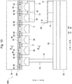
Figure 10] Figure 10 is a partial front view showing a press brake according to a first modification of the second embodiment. - [
Figure 11] Figure 11 is an enlarged cross-sectional view along the XI-XI line inFigure 10 . - [
Figure 12] Figure 12 is a partial front view showing a press brake according to a second modification of the second embodiment. - [
Figure 13] Figure 13 is an enlarged cross-sectional view along the XIII-XIII line inFigure 12 . - Embodiments (including modifications) of the present invention will be described with reference to
Figure 1 to Figure 6 . - Note that "a lateral direction" includes meanings of a lateral direction of an upper tool, a lateral direction of a lower tool, a lateral direction of an upper tool holder, and a lateral direction of a press brake unless otherwise noted. "A left-right direction" is one of horizontal directions, and is the same as the lateral direction of the press brake. "A front-rear direction" is one of the horizontal directions, and a direction orthogonal to the left-right direction. "A pressurizing center position" refers to a position of a virtual vertical plane passing through a distal end of a punch in the front-rear direction. In the drawings, "L" indicates a left direction, "R" indicates a right direction, "FF" indicates a front direction, "FR" indicates a rear direction, "U" indicates an up direction, and "D" indicates a down direction.
- As shown in
Figure 1 andFigure 2 , apress brake 10 according to a first embodiment is a processing machine that performs bending of a plate-shaped workpiece (sheet metal) W by cooperation of an automatically changeable upper tool (punch) 12 and a lower tool (die) 14. Anengagement hole 12h is formed through a center of theupper tool 12 in the left-right direction (lateral direction). In ashank 12s (seeFigure 4 ) of theupper tool 12, ananti-drop groove 12g (seeFigure 4 ) is formed along the left-right direction. Anengagement hole 14h is formed through a center of thelower tool 14 in the left-right direction. - The
press brake 10 includes amain frame 16. Themain frame 16 includes a pair ofside plates 18 separated from and opposed to each other in the left-right direction, and a plurality of beam members 20 (only one is shown in the drawing) coupling the pair ofside plates 18. In a lower part of themain frame 16, a lower table 22 extending in the left-right direction is provided. In an upper part of themain frame 16, an upper table 24 extending in the left-right direction is vertically movably provided. In each of upper parts of theside plates 18, ahydraulic cylinder 26 is provided as a vertically-driving actuator that vertically moves the upper table 24 relative to themain frame 16. Note that instead of configuring the upper table 24 to be vertically movable, the lower table 22 may be configured to be vertically movable. As the vertically-driving actuator, a servo motor may be used in place of thehydraulic cylinder 26. - As shown in
Figure 2 to Figure 6 , on a lower end side of a front surface of the upper table 24, a machining-finishedsurface 24f is formed along the left-right direction. A plate-shapedattachment base 28 extending in the left-right direction is attached to the machining-finishedsurface 24f of the upper table 24 with a plurality ofattachment bolts 30. Eachattachment bolt 30 penetrates abolt hole 28h formed in theattachment base 28. Theattachment base 28 has a front surface and a back surface that are finished by machining. On a lower end side of theattachment base 28, a plurality of protruding tabs (protrusions) 32 protruding downward are formed at even intervals in the left-right direction. Note that the plurality of protrudingtabs 32 may only be arranged at intervals in the left-right direction, and do not have to be arranged at even intervals. - A plurality of fixture plates (fastening plates) 34 are attached to the front surface of the
attachment base 28 at intervals in the left-right direction withattachment bolts 36. That is, on the front surface of the upper table 24, thefixture plates 34 are arranged at intervals in the left-right direction via theattachment base 28 and theattachment bolts 36. At a lower end of a back surface of eachfixture plate 34, apawl 34c is formed along the left-right direction. Eachattachment bolt 36 penetrates abolt hole 28v formed in theattachment base 28. - On a lower end side of the upper table 24,
upper tool holders 38 removably holding theupper tool 12 are arranged at intervals in the left-right direction. Eachupper tool holder 38 includes anattachment plate 40 to be pressed onto the front surface of the upper table 24 with thefixture plate 34. That is, on the lower end side of the upper table 24, theupper tool holders 38 are arranged at intervals in the left-right direction via thefixture plates 34. Further, eachupper tool holder 38 is disposed between the protrudingtabs 32 adjacent to each other in the left-right direction in the front surface of theattachment base 28. Theupper tool holder 38 includes, for example, a configuration disclosed in Patent Literature 2 described above. The configuration of theupper tool holder 38 will be briefly described hereinafter. - As shown in
Figure 2 to Figure 5 , in an upper part of a front surface of theattachment plate 40, anengagement groove 40g to be engaged with thepawl 34c of eachfixture plate 34 is formed. A holder main body (intermediate plate) 42 is attached to a lower part of a rear surface of theattachment plate 40 with a plurality of attachment bolts (not shown). The holdermain body 42 is located on a lower side of the upper table 24. That is, the holdermain body 42 is disposed on the lower side of the upper table 24 with theattachment plate 40. An upper surface of the holdermain body 42 is formed as a tiltedsurface 42f tilted in the front-rear direction. - A
wedge member 44 is disposed between the holdermain body 42 and the upper table 24, and disposed at a position adjustable relative to the holdermain body 42 in the front-rear direction. A lower surface of thewedge member 44 is formed as a tiltedsurface 44f tilted in the front-rear direction. The tiltedsurface 44f comes in sliding contact with the tiltedsurface 42f of the holdermain body 42. In a center of theattachment plate 40 in the left-right direction, apush bolt 46 for pushing thewedge member 44 rearward is disposed. On right and left sides of thepush bolt 46 of theattachment plate 40, pullbolts 48 for pulling thewedge member 44 forward are arranged, respectively. - A
clamp plate 50 configured to press theshank 12s of theupper tool 12 onto the holdermain body 42 is swingably attached to a front surface of the holdermain body 42 with a plurality ofsupport shafts 52. Aclamp plate 50 configured to press theshank 12s onto the holdermain body 42 is also swingably attached to a back surface of the holdermain body 42 with a plurality ofsupport shafts 52. On a lower end side of eachclamp plate 50, ahook member 54 engageable in theanti-drop groove 12g of theupper tool 12 is formed. Also, in the holdermain body 42, a clamp plate cylinder (not shown) for a pressing operation of a pair ofclamp plates 50 is disposed. Aspring 56 that urges eachclamp plate 50 in a release direction of the pressing operation is interposed between the holdermain body 42 and eachclamp plate 50. - As shown in
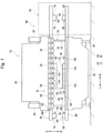
Figure 2 ,Figure 3 andFigure 6 , in the present embodiment, theattachment plate 40 in eachupper tool holder 38 is interposed between the protrudingtabs 32 adjacent to each other in the left-right direction. Each protrudingtab 32 of theattachment base 28 is a first regulating member that comes in contact with a side surface of theattachment plate 40 to regulate side misalignment (positional shift in the left-right direction) of theupper tool holder 38. That is, the protruding tabs 32 (first regulating members) are arranged on opposite left and right sides of eachattachment plate 40 in the front surface of the upper table 24, respectively. Also, an escape space S for avoiding interference of a side flange Wf with a part (upper tool holder 38 or the like) of thepress brake 10 due to folding-up of the workpiece W is formed between theupper tool holders 38 adjacent to each other. Note thatFigure 6 shows theupper tool holders 38 and connectingmembers 64 with dashed lines. - As shown in
Figure 1 andFigure 2 , alower tool holder 58 removably holding thelower tool 14 is provided at an upper end of the lower table 22. Thelower tool holder 58 extends in the left-right direction. Thelower tool holder 58 includes, for example, a configuration disclosed in Patent Literature 1 described above. - As shown in
Figure 1 , thepress brake 10 is equipped with an auto tool changer (ATC) 60 for automatically changing theupper tool 12 and thelower tool 14. On one side (right side) of themain frame 16 of theATC 60 in the left-right direction, atool storage 62 that stores a plurality ofupper tools 12 and a plurality oflower tools 14 is disposed. Thetool storage 62 includes, for example, a configuration disclosed in Patent Literatures 1, 3 and 4 described above. Thetool storage 62 includes, in an upper part, a plurality of upper stockers (not shown) holding the plurality ofupper tools 12. The selected upper stocker is positioned at an upper tool exchange position located on a side of theupper tool holder 38. Also, thetool storage 62 includes, in a lower part, a plurality of lower stockers (not shown) holding a plurality oflower tools 14. The selected lower stocker is positioned at a lower tool exchange position located on a side of thelower tool holder 58. - As shown in
Figure 2 to Figure 6 , the rectangular plate-shaped connectingmembers 64 are attached to back surfaces of the respective protrudingtabs 32 of theattachment base 28 with a plurality ofattachment bolts 66. Eachattachment bolt 66 penetrates abolt hole 28b formed in theattachment base 28. Each connectingmember 64 on a distal end side (rear end side) is located on a back side of the upper table 24. Each connectingmember 64 has a base-end face (front end face) and a distal-end face (rear end face) finished by machining. To prevent deflection of the connectingmembers 64, the connectingmembers 64 are coupled to a lower end face of the upper table 24 with a plurality ofcoupling bolts 68. Each connectingmember 64 is a second regulating member that comes in contact with a side surface of the holdermain body 42 to regulate side misalignment of theupper tool holder 38. That is, the connecting members 64 (second regulating members) are arranged on opposite left and right sides of theupper tool holder 38 on the lower end side of the upper table 24, respectively. - As shown in
Figure 1 ,Figure 4 andFigure 5 , anupper guide member 70 extending in the left-right direction is integrally coupled to a rear end face of the connectingmember 64 with acoupling bolt 72. Theupper guide member 70 has a left end protruding leftward from the upper table 24. Theupper guide member 70 has a right end protruding rightward from the upper table 24, and overlapping with thetool storage 62. Theupper guide member 70 includes, on a back surface, arail 70r extending in the left-right direction. Also, on therail 70r, a pair of uppertool changing units 74 for automatically changing theupper tool 12 are provided movably in the left-right direction. That is, theupper guide member 70 supports the pair of uppertool changing units 74 as moving bodies movably in the left-right direction on the back side of the upper table 24. Each uppertool changing unit 74 can remove theupper tool 12 from the upper tool holder 38 (or the upper stocker positioned at the upper tool exchange position) in the front-rear direction and left-right direction. Also, the uppertool changing unit 74 can attach theupper tool 12 to the upper tool holder 38 (or the upper stocker positioned at the upper tool exchange position) in the front-rear direction and left-right direction. - The upper
tool changing unit 74 includes, for example, a configuration disclosed in Patent Literature 1 described above. The uppertool changing unit 74 includes an upper unitmain body 76 provided movably in the left-right direction on therail 70r of theupper guide member 70, and an uppertool retention member 78 provided in the upper unitmain body 76. The uppertool retention member 78 is a rod-shaped or hook-shaped member engageable in theengagement hole 12h of theupper tool 12. The uppertool retention member 78 is configured to be movable in the front-rear direction and up-down direction relative to the upper unitmain body 76. Note that the uppertool retention member 78 does not have to be movable vertically to the upper unitmain body 76. A changing operation by the uppertool changing units 74 is not described. - As shown in
Figure 1 , alower guide member 80 extending in the left-right direction is attached to a back surface of thelower tool holder 58. Thelower guide member 80 has a left end protruding leftward from the lower table 22. Thelower guide member 80 has a right end protruding rightward from the lower table 22, and overlapping with atool storage 62 side. In thelower guide member 80, a pair of lowertool changing units 82 for automatically changing thelower tool 14 are provided movably in the left-right direction. Each lowertool changing unit 82 can remove thelower tool 14 from the lower tool holder 58 (or the lower stocker positioned at the lower tool exchange position) in the front-rear direction and left-right direction. Also, the lowertool changing unit 82 can attach thelower tool 14 to the lower tool holder 58 (or the lower stocker positioned at the lower tool exchange position) in the front-rear direction and left-right direction. - The lower
tool changing unit 82 includes, for example, a configuration disclosed in Patent Literature 1 described above. The lowertool changing unit 82 includes a lower unitmain body 84 provided movably in the left-right direction in thelower guide member 80, and a lowertool retention member 86 provided in the lower unitmain body 84. The lowertool retention member 86 is a rod-shaped or hook-shaped member engageable in theengagement hole 14h of thelower tool 14. The lowertool retention member 86 is configured to be movable in the front-rear direction and a direction relative to the lower unitmain body 84. Note that a changing operation by the lowertool changing units 82 is not described. - Subsequently, description will be made as to effects of the present embodiment.
- In the present embodiment, the
attachment base 28 is provided on the lower end side of the front surface of the upper table 24, and theupper tool holder 38 is disposed between the protrudingtabs 32 adjacent to each other in the left-right direction in the front surface of theattachment base 28. That is, theupper tool holder 38 is attached to the lower end side of the front surface of the upper table 24 via theattachment base 28. The attachment surface of theupper tool holder 38 is the front surface of theattachment base 28, and the attachment reference surface of theupper tool holder 38 in the front-rear direction is the machining-finishedsurface 24f of the upper table 24 on the lower end side of the front surface. - Further, in the present embodiment, the connecting
member 64 is attached to the back surface of each protrudingtab 32 of theattachment base 28, and theupper guide member 70 is integrally coupled to the distal-end face of each connectingmember 64. That is, theupper guide member 70 is attached to the lower end side of the front surface of the upper table 24 via the connectingmember 64 and theattachment base 28. The attachment surface of theupper guide member 70 is the distal-end face of the connectingmember 64, and hence the attachment reference surface of theupper guide member 70 in the front-rear direction is the machining-finishedsurface 24f of the upper table 24 on the lower end side of the front surface via the connectingmember 64. - Therefore, according to the present embodiment, the attachment reference surface of the general-purpose upper tool holder and the attachment reference surface of the upper guide member can be the same. Also, according to the present embodiment, in the case of equipping the stand-
alone press brake 10 with the uppertool changing unit 74 as the moving body, parallelism of theupper guide member 70 to theupper tool holders 38 can be kept with high accuracy, and reliability of the changing operation by the uppertool changing unit 74 can be sufficiently secured. - Further, in the present embodiment, the protruding tabs 32 (first regulating members) are arranged on the opposite left and right sides of the
attachment plate 40 in the front surface of the upper table 24, respectively. The connecting members 64 (second regulating members) are arranged on the opposite left and right sides of eachupper tool holder 38 on the lower end side of the upper table 24, respectively. Therefore, even when the deflections of the upper table 24 and the lower table 22 increase due to the bending load during the bending of the workpiece W, the protrudingtabs 32 and the connectingmembers 64 can regulate (prevent) the side misalignment of theupper tool holder 38 to the upper table 24. As a result, the reliability of the changing operation by the uppertool changing unit 74 can be more sufficiently secured. Also, bending defect can be prevented, and the bending can be performed with high accuracy and stability, while avoiding the interference of the side flange Wf with theupper tool holder 38 or the like. - As shown in
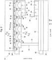
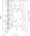
Figure 7 to Figure 9 , apress brake 88 according to a second embodiment is a processing machine that performs bending of a plate-shaped workpiece (sheet metal) W by cooperation of anupper tool 12 and alower tool 14. In the present embodiment, anengagement hole 12h (seeFigure 2 ) is not formed in theupper tool 12, but theengagement hole 12h may be formed. Anengagement hole 14h (seeFigure 2 ) is not formed in thelower tool 14, but theengagement hole 14h may be formed. - The
press brake 88 includes a configuration similar to the configuration of the press brake 10 (seeFigure 1 ) except that the press brake is not equipped with an ATC 60 (seeFigure 1 ). Hereinafter, description will be made only as to a configuration of thepress brake 88 that is different from the configuration of thepress brake 10. Note that components of thepress brake 88 corresponding to the components of thepress brake 10 are denoted with the same reference signs, and the components are not described in detail. - A lower end face of each protruding tab (protrusion) 32 of an
attachment base 28 is positioned higher than a lower end face of an upper table 24. A connecting member 64 (seeFigure 5 ) is not provided on a back surface of the protrudingtab 32. The protrudingtab 32 is a regulating member that comes in contact with a side surface of anattachment plate 40 to regulate side misalignment (positional shift in a left-right direction) of eachupper tool holder 38. That is, the protruding tabs 32 (regulating members) are arranged on opposite left and right sides of eachattachment plate 40 in a front surface of the upper table 24, respectively. Note that the lower end face of the protrudingtab 32 may be positioned as high as the lower end face of the upper table 24 instead of being positioned higher than the lower end face of the upper table 24. - The
upper tool holder 38 includes, for example, a mechanical type configuration disclosed in Patent Literature 5 described above. Alower tool holder 58 includes, for example, a mechanical type configuration disclosed in Patent Literature 6 described above. - Subsequently, description will be made as to effects of the present embodiment.
- The protruding tabs 32 (regulating members) are arranged on the opposite left and right sides of each
attachment plate 40 in the front surface of the upper table 24, respectively. Therefore, even when deflections of the upper table 24 and a lower table 22 increase due to bending load during the bending of the workpiece W, the protrudingtabs 32 can regulate (prevent) side misalignment of theupper tool holder 38 to the upper table 24. As a result, bending defect can be prevented, and the bending of the workpiece W can be performed with high accuracy and stability, while avoiding interference of a side flange Wf with theupper tool holder 38 or the like. - Also, since the lower end face of each protruding
tab 32 is positioned higher than the lower end face of the upper table 24, a height of the side flange Wf is not restricted by the protrudingtab 32 as the regulating member, and a degree of freedom in bending of the workpiece W can be sufficiently secured. That is, the degree of freedom in bending of the workpiece W can be sufficiently secured, and additionally, the bending of the workpiece W can be performed with high accuracy and stability. Even when the lower end face of the protrudingtab 32 is positioned as high as the lower end face of the upper table 24, the degree of freedom in bending can be sufficiently secured. If the lower end face of the protrudingtab 32 is positioned lower than the lower end face of the upper table 24, the degree of freedom in bending cannot be secured. - As shown in
Figure 10 andFigure 11 , apress brake 88A according to a first modification of the second embodiment includes a configuration similar to the press brake 88 (seeFigure 8 ). Hereinafter, description will be made only as to a configuration of thepress brake 88A that is different from the configuration of thepress brake 88. Note that components of thepress brake 88A corresponding to the components of thepress brake 88 are denoted with the same reference signs, and the components are not described in detail. - In the configuration of the
press brake 88A, the attachment base 28 (seeFigure 8 ) is omitted. A plurality offixture plates 34 are attached to a lower end side of a front surface of an upper table 24 at intervals in a left-right direction withattachment bolts 36. Thefixture plates 34 are fixed directly to the front surface of the upper table 24. (An upper part of eachfixture plate 34 is thicker only as much as a thickness of theattachment base 28.) - Rectangular plate-shaped
regulating members 90 are attached to opposite left and right sides of eachupper tool holder 38 in the front surface of the upper table 24 withattachment bolts 92. Each regulatingmember 90 comes in contact with a side surface of anattachment plate 40 to regulate side misalignment (positional shift in a left-right direction) of theupper tool holder 38. A lower end face of the regulatingmember 90 is positioned higher than a lower end face of the upper table 24. Note that the lower end face of the regulatingmember 90 may be positioned as high as the lower end face of the upper table 24 instead of being positioned higher than the lower end face of the upper table 24. - Subsequently, description will be made as to effects of the present modification.
- The regulating
members 90 are arranged on the opposite left and right sides of eachupper tool holder 38 in the front surface of the upper table 24, respectively. Therefore, even when deflections of the upper table 24 and a lower table 22 increase due to bending load during the bending of a workpiece W, the regulatingmembers 90 can regulate side misalignment of theupper tool holder 38 to the upper table 24. As a result, bending defect can be prevented, and the bending of the workpiece W can be performed with high accuracy and stability, while avoiding interference of a side flange Wf with theupper tool holder 38 or the like. - Also, since the lower end face of each regulating
member 90 is positioned higher than the lower end face of the upper table 24, a height of the side flange Wf is not restricted by the regulatingmember 90, and a degree of freedom in bending of the workpiece W can be sufficiently secured. That is, the degree of freedom in bending of the workpiece W can be sufficiently secured, and additionally, the bending of the workpiece W can be performed with high accuracy and stability in the same manner as in the aforementioned second embodiment. Even when the lower end face of the regulatingmember 90 is positioned as high as the lower end face of the upper table 24, the degree of freedom in bending can be sufficiently secured. If the lower end face of the regulatingmember 90 is positioned lower than the lower end face of the upper table 24, the degree of freedom in bending cannot be secured. - As shown in
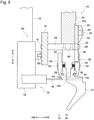
Figure 12 andFigure 13 , apress brake 88B according to a second modification of the second embodiment includes a configuration similar to the press brake 88 (seeFigure 8 ). Hereinafter, description will be made only as to a configuration of thepress brake 88B that is different from the configuration of thepress brake 88. Note that components of thepress brake 88B corresponding to the components of thepress brake 88 are denoted with the same reference signs, and the components are not described in detail. - In the configuration of the
press brake 88B, the attachment base 28 (seeFigure 8 ) is omitted. A plurality offixture plates 34 are attached to a lower end side of a front surface of an upper table 24 at intervals in a left-right direction withattachment bolts 36. Thefixture plates 34 are fixed directly to the front surface of the upper table 24. (An upper part of eachfixture plate 34 is thicker only as much as a thickness of theattachment base 28.) - Further, L-shaped
regulating members 94 are attached on opposite left and right sides of eachupper tool holder 38 on a lower end side of a back surface of the upper table 24 withattachment bolts 96. Each regulatingmember 94 comes in contact with a side surface of awedge member 44 to regulate side misalignment (positional shift in the left-right direction) of eachupper tool holder 38. The regulatingmember 94 includes avertical part 94a fixed to the back surface of the upper table 24 with theattachment bolt 96, and ahorizontal part 94b protruding forward from a lower end of thevertical part 94a. A front (front surface) of thehorizontal part 94b of the regulatingmember 94 is located behind a pressurizing center position BL. - Subsequently, description will be made as to operations and effects of the present modification.
- The regulating
members 94 are arranged on the opposite left and right sides of eachupper tool holder 38 on the lower end side of the back surface of the upper table 24, respectively. Therefore, even when deflections of the upper table 24 and a lower table 22 increase due to bending load during bending of a workpiece W, the regulatingmembers 94 can regulate side misalignment of theupper tool holder 38 to the upper table 24. As a result, bending defect can be prevented, and the bending of the workpiece W can be performed with high accuracy and stability, while avoiding interference of a side flange Wf with theupper tool holder 38 or the like. - Also, since the front of the
horizontal part 94b of the regulatingmember 94 is located behind the pressurizing center position BL, a height of the side flange Wf is not restricted by the regulatingmember 94, and a degree of freedom in bending of the workpiece W can be sufficiently secured. That is, the degree of freedom in bending of the workpiece W can be sufficiently secured, and additionally, the bending of the workpiece W can be performed with high accuracy and stability in the same manner as in the aforementioned second embodiment. - Entire contents of
Japanese Patent Application No. 2019-87437 (filed on May 7, 2019 Japanese Patent Application No. 2020-71715 (filed on April 13, 2020
Claims (7)
- A press brake comprising:an attachment base provided on a front surface of an upper table, extending in a left-right direction, and including a plurality of protruding tabs protruding downward and formed at intervals in the left-right direction;an upper tool holder disposed between protruding tabs adjacent to each other in the left-right direction in a front surface of the attachment base, and holding an upper tool;a plurality of connecting members attached to back surfaces of the plurality of protruding tabs, respectively, and comprising distal ends located on a back side of the upper table; anda guide member coupled to distal-end faces of the plurality of connecting members, extending in the left-right direction, and supporting a moving body movably in the left-right direction on the back side of the upper table.
- The press brake according to claim 1, wherein each of the protruding tabs is a first regulating member configured to regulate side misalignment of the upper tool holder to the upper table.
- The press brake according to claim 1 or 2, wherein each of the connecting members is a second regulating member configured to regulate side misalignment of the upper tool holder to the upper table.
- The press brake according to any one of claims 1 to 3, wherein the moving body is an upper tool changing unit configured to automatically change the upper tool relative to the upper tool holder.
- A press brake comprising:a plurality of fixture plates arranged at intervals in a left-right direction on a front surface of an upper table;a plurality of upper tool holders arranged at intervals in the left-right direction on a lower end side of the upper table, including an attachment plate to be pressed onto a front side of the upper table by each fixture plate, and holding an upper tool; anda regulating member disposed on each of opposite left and right sides of each upper tool holder in the upper table, and configured to regulate side misalignment of the upper tool holder to the upper table.
- The press brake according to claim 5, wherein each of the regulating members is provided on the front surface of the upper table, and
each lower end face of the regulating member is positioned higher than a lower end face of the upper table or as high as the lower end face of the upper table. - The press brake according to claim 5, wherein each of the regulating members is provided on a lower end side of a back surface of the upper table, and
a front surface of each regulating member is located behind a pressurizing center position.
Priority Applications (1)
| Application Number | Priority Date | Filing Date | Title |
|---|---|---|---|
| EP25187528.2A EP4603204B1 (en) | 2019-05-07 | 2020-04-27 | Press brake |
Applications Claiming Priority (3)
| Application Number | Priority Date | Filing Date | Title |
|---|---|---|---|
| JP2019087437 | 2019-05-07 | ||
| JP2020071715A JP6785392B1 (en) | 2019-05-07 | 2020-04-13 | Press brake |
| PCT/JP2020/017895 WO2020226084A1 (en) | 2019-05-07 | 2020-04-27 | Press brake |
Related Child Applications (2)
| Application Number | Title | Priority Date | Filing Date |
|---|---|---|---|
| EP25187528.2A Division EP4603204B1 (en) | 2019-05-07 | 2020-04-27 | Press brake |
| EP25187528.2A Division-Into EP4603204B1 (en) | 2019-05-07 | 2020-04-27 | Press brake |
Publications (3)
| Publication Number | Publication Date |
|---|---|
| EP3967417A1 true EP3967417A1 (en) | 2022-03-16 |
| EP3967417A4 EP3967417A4 (en) | 2022-06-22 |
| EP3967417B1 EP3967417B1 (en) | 2025-10-01 |
Family
ID=73050602
Family Applications (2)
| Application Number | Title | Priority Date | Filing Date |
|---|---|---|---|
| EP25187528.2A Active EP4603204B1 (en) | 2019-05-07 | 2020-04-27 | Press brake |
| EP20802239.2A Active EP3967417B1 (en) | 2019-05-07 | 2020-04-27 | Press brake |
Family Applications Before (1)
| Application Number | Title | Priority Date | Filing Date |
|---|---|---|---|
| EP25187528.2A Active EP4603204B1 (en) | 2019-05-07 | 2020-04-27 | Press brake |
Country Status (4)
| Country | Link |
|---|---|
| US (1) | US12036599B2 (en) |
| EP (2) | EP4603204B1 (en) |
| CN (1) | CN113784807B (en) |
| WO (1) | WO2020226084A1 (en) |
Families Citing this family (4)
| Publication number | Priority date | Publication date | Assignee | Title |
|---|---|---|---|---|
| CN112423907A (en) * | 2018-07-17 | 2021-02-26 | 株式会社天田集团 | Metal die for bending machine |
| JP6741824B1 (en) * | 2019-05-16 | 2020-08-19 | 株式会社アマダ | Bending system and die transfer method |
| CN114888136B (en) * | 2022-07-14 | 2022-09-23 | 瑞铁机床(苏州)股份有限公司 | Automatic change quick retooling center of bending |
| CN116116945A (en) * | 2022-11-23 | 2023-05-16 | 南通腾中机械有限公司 | A sheet metal bending machine for bending sheets of different thicknesses |
Family Cites Families (47)
| Publication number | Priority date | Publication date | Assignee | Title |
|---|---|---|---|---|
| JPS5947861B2 (en) | 1976-12-28 | 1984-11-21 | 日本電気株式会社 | Plasma display panel with alarm display |
| JPS5841800B2 (en) | 1980-08-29 | 1983-09-14 | 富士通株式会社 | Method of forming ceramic multilayer substrate |
| JPS6041292Y2 (en) | 1981-11-19 | 1985-12-16 | 丸機械工業株式会社 | folding machine |
| CH655874A5 (en) * | 1982-06-07 | 1986-05-30 | Haemmerle Ag Maschf | TOOL DEVICE ON A BENDING PRESS. |
| JPH06234018A (en) | 1993-02-09 | 1994-08-23 | Komatsu Ltd | Automatic die changing device of press brake |
| JPH09220618A (en) | 1996-02-13 | 1997-08-26 | Toupure Kk | Upper mold device for V-shaped bending machine |
| JPH10211521A (en) * | 1997-01-24 | 1998-08-11 | Murata Mach Ltd | Mold width adjusting device for sheet bending machine |
| JPH10263708A (en) | 1997-03-24 | 1998-10-06 | Murata Mach Ltd | Mold width adjustment device for folding machine |
| JP3841923B2 (en) | 1997-06-20 | 2006-11-08 | 株式会社アマダ | Mold changing method, mold storage device and bending system in bending machine |
| JP4558852B2 (en) | 1998-08-28 | 2010-10-06 | 株式会社アマダ | Mold and mold changer |
| EP2143506B1 (en) | 1999-01-13 | 2013-02-27 | Amada Company, Limited | A divided tool exchange and mounting method and device for a press brake |
| JP2001001048A (en) * | 1999-06-23 | 2001-01-09 | Amada Co Ltd | Sheet metal bending machine and its bending system |
| IT1317545B1 (en) * | 2000-05-16 | 2003-07-09 | Abiemme Srl | PNEUMATIC CONTROL SYSTEM FOR RAPID CLAMPING OF TOOLS IN BENDING PRESSES |
| DE10060405B4 (en) | 2000-12-05 | 2007-03-15 | Bayerische Motoren Werke Ag | Inner gripper for pipes and bores |
| JP2003071519A (en) | 2001-09-03 | 2003-03-11 | Amada Co Ltd | Mold changer |
| JP4242204B2 (en) * | 2003-05-19 | 2009-03-25 | 株式会社アマダ | Bending machine |
| JP4233921B2 (en) | 2003-05-21 | 2009-03-04 | 株式会社アマダ | Mold fixing device |
| JP4582621B2 (en) | 2003-06-23 | 2010-11-17 | 株式会社アマダ | Bending machine |
| JP4883668B2 (en) | 2005-06-15 | 2012-02-22 | 株式会社アマダ | Bending apparatus, mold arrangement method and mold stocker selection method |
| US7168286B1 (en) | 2005-10-29 | 2007-01-30 | Pelech Bruno J | Device and method for securing a punch tool to a ram portion of a press brake |
| ATE501810T1 (en) | 2006-06-01 | 2011-04-15 | Wila Bv | INTERCHANGEABLE TOOL/MANIPULATOR COMBINATION |
| WO2008050458A1 (en) | 2006-10-27 | 2008-05-02 | Komatsu Industries Corporation | Punch, handle usable therefor, and punch with handle |
| JP2010284705A (en) * | 2009-06-15 | 2010-12-24 | Shinjo Mfg Co Ltd | Nut supply apparatus to bonding machine |
| JP5531878B2 (en) * | 2010-09-15 | 2014-06-25 | 村田機械株式会社 | Press machine |
| JP5662183B2 (en) * | 2011-02-01 | 2015-01-28 | 株式会社アマダ | Upper holder for press brake |
| JP5841800B2 (en) | 2011-10-20 | 2016-01-13 | 株式会社アマダホールディングス | Upper mold holder |
| JP2013111610A (en) * | 2011-11-29 | 2013-06-10 | Amada Co Ltd | Device for bending plate material |
| JP2014004604A (en) | 2012-06-25 | 2014-01-16 | Amada Co Ltd | Mold mounting stocker, mold storage device, mold and hand storage device, mold exchange method by robot and control device for the same |
| JP5970339B2 (en) | 2012-11-01 | 2016-08-17 | 株式会社アマダホールディングス | Mold changer |
| JP6148883B2 (en) * | 2013-03-14 | 2017-06-14 | 株式会社アマダホールディングス | Press brake |
| JP2015120185A (en) | 2013-12-24 | 2015-07-02 | 株式会社アマダホールディングス | Press brake intermediate plate mounting device |
| JP3190141U (en) * | 2014-02-06 | 2014-04-17 | 東海シヤリング株式会社 | Mold for bending machine |
| JP6364497B2 (en) | 2014-02-10 | 2018-07-25 | サルヴァニーニ イタリア エッセ.ピ.ア.SALVAGNINI ITALIA S.p.A. | Bending machine for sheet metal |
| AT515526B1 (en) | 2014-08-12 | 2015-10-15 | Trumpf Maschinen Austria Gmbh | Bending tool and gripping device for manipulating the bending tool |
| AT515781B1 (en) | 2014-10-08 | 2015-12-15 | Trumpf Maschinen Austria Gmbh | Handling system for bending tools |
| JP5947861B2 (en) | 2014-10-24 | 2016-07-06 | 株式会社アマダホールディングス | Method of attaching / detaching mold of press brake and mold storage device |
| ITUA20164119A1 (en) | 2016-06-06 | 2017-12-06 | Dalma Srl | Tool magazine for bending press |
| IT201600100916A1 (en) | 2016-10-07 | 2018-04-07 | Andrea Argentin | Improved press brake |
| CN106734644A (en) | 2016-12-22 | 2017-05-31 | 上海机床厂有限公司 | The automatic mounting mechanism of mould on numerical control bender |
| CN107052095A (en) * | 2017-01-03 | 2017-08-18 | 广州市婵昕生物科技有限责任公司 | A kind of power equipment part bending apparatus |
| CN206689300U (en) * | 2017-04-24 | 2017-12-01 | 东莞市技新运动用品有限公司 | A high-precision bending forming stamping die |
| IT201700052500A1 (en) * | 2017-05-15 | 2018-11-15 | Salvagnini Italia Spa | BENDING MACHINE FOR METAL SHEETS |
| JP2019087437A (en) | 2017-11-08 | 2019-06-06 | パナソニックIpマネジメント株式会社 | Display unit |
| CN207629060U (en) * | 2017-12-28 | 2018-07-20 | 九江昌华模具科技有限公司 | A kind of contractile hardware dies of red needle |
| CN108405671A (en) * | 2018-05-09 | 2018-08-17 | 郑州宸通机械设备有限公司 | A kind of dog-ear device for hardware processing |
| JP6947861B2 (en) | 2018-08-06 | 2021-10-13 | 株式会社ユニバーサルエンターテインメント | Pachinko machine |
| JP6511682B1 (en) | 2018-10-31 | 2019-05-15 | オムロン株式会社 | INFORMATION PROCESSING APPARATUS, INFORMATION PROCESSING METHOD, INFORMATION PROCESSING PROGRAM, AND RECORDING MEDIUM |
-
2020
- 2020-04-27 EP EP25187528.2A patent/EP4603204B1/en active Active
- 2020-04-27 WO PCT/JP2020/017895 patent/WO2020226084A1/en not_active Ceased
- 2020-04-27 US US17/608,624 patent/US12036599B2/en active Active
- 2020-04-27 CN CN202080033758.9A patent/CN113784807B/en active Active
- 2020-04-27 EP EP20802239.2A patent/EP3967417B1/en active Active
Also Published As
| Publication number | Publication date |
|---|---|
| CN113784807B (en) | 2023-08-15 |
| US20220226876A1 (en) | 2022-07-21 |
| EP4603204B1 (en) | 2026-08-19 |
| EP3967417B1 (en) | 2025-10-01 |
| EP4603204A2 (en) | 2025-08-20 |
| EP4603204A3 (en) | 2025-11-26 |
| US12036599B2 (en) | 2024-07-16 |
| WO2020226084A1 (en) | 2020-11-12 |
| CN113784807A (en) | 2021-12-10 |
| EP3967417A4 (en) | 2022-06-22 |
Similar Documents
| Publication | Publication Date | Title |
|---|---|---|
| EP3967417B1 (en) | Press brake | |
| US20250289046A1 (en) | Bending system and correcting method for tool misalignment | |
| US20140283576A1 (en) | Sheet material processing apparatus, press die, and die setting body | |
| EP3825028B1 (en) | Upper tool stocker | |
| EP0890396A1 (en) | A device for the automatic replacement of the tools in a bending machine | |
| KR102481088B1 (en) | Hand for exchanging chuck's claws, automatic method for exchanging chuck's claws, and automatic claw exchange system | |
| JP5054681B2 (en) | Tool fastening device for wedge drive | |
| JP2008546538A5 (en) | ||
| JP4076342B2 (en) | Workpiece, in particular sheet metal working machine, having at least one bending station and at least one joining device | |
| JP6785392B1 (en) | Press brake | |
| WO2019146447A1 (en) | Press brake | |
| CN113840672B (en) | Bending system and die conveying method | |
| US12440881B2 (en) | Method for installing divided upper tool to upper tool holder provided on upper table of press brake, tool changer, and tool stocker | |
| WO2019239883A1 (en) | Split die attachment method and press brake | |
| JP3783944B2 (en) | Presser die mounting structure for plate bending machine | |
| JP7787620B1 (en) | press brake equipment | |
| KR20260015127A (en) | Bending device and bending method using the same | |
| WO2005120740A1 (en) | Hemming die and hemming die apparatus | |
| JP4824977B2 (en) | Press brake | |
| JP2023089640A (en) | Inserting die device, press brake, and bending method for press brake |
Legal Events
| Date | Code | Title | Description |
|---|---|---|---|
| STAA | Information on the status of an ep patent application or granted ep patent |
Free format text: STATUS: THE INTERNATIONAL PUBLICATION HAS BEEN MADE |
|
| PUAI | Public reference made under article 153(3) epc to a published international application that has entered the european phase |
Free format text: ORIGINAL CODE: 0009012 |
|
| STAA | Information on the status of an ep patent application or granted ep patent |
Free format text: STATUS: REQUEST FOR EXAMINATION WAS MADE |
|
| 17P | Request for examination filed |
Effective date: 20211102 |
|
| AK | Designated contracting states |
Kind code of ref document: A1 Designated state(s): AL AT BE BG CH CY CZ DE DK EE ES FI FR GB GR HR HU IE IS IT LI LT LU LV MC MK MT NL NO PL PT RO RS SE SI SK SM TR |
|
| A4 | Supplementary search report drawn up and despatched |
Effective date: 20220523 |
|
| RIC1 | Information provided on ipc code assigned before grant |
Ipc: B21D 37/04 20060101ALI20220518BHEP Ipc: B21D 5/02 20060101AFI20220518BHEP |
|
| DAV | Request for validation of the european patent (deleted) | ||
| DAX | Request for extension of the european patent (deleted) | ||
| P01 | Opt-out of the competence of the unified patent court (upc) registered |
Effective date: 20230527 |
|
| GRAP | Despatch of communication of intention to grant a patent |
Free format text: ORIGINAL CODE: EPIDOSNIGR1 |
|
| STAA | Information on the status of an ep patent application or granted ep patent |
Free format text: STATUS: GRANT OF PATENT IS INTENDED |
|
| INTG | Intention to grant announced |
Effective date: 20250507 |
|
| GRAS | Grant fee paid |
Free format text: ORIGINAL CODE: EPIDOSNIGR3 |
|
| GRAA | (expected) grant |
Free format text: ORIGINAL CODE: 0009210 |
|
| STAA | Information on the status of an ep patent application or granted ep patent |
Free format text: STATUS: THE PATENT HAS BEEN GRANTED |
|
| AK | Designated contracting states |
Kind code of ref document: B1 Designated state(s): AL AT BE BG CH CY CZ DE DK EE ES FI FR GB GR HR HU IE IS IT LI LT LU LV MC MK MT NL NO PL PT RO RS SE SI SK SM TR |
|
| REG | Reference to a national code |
Ref country code: GB Ref legal event code: FG4D Ref country code: CH Ref legal event code: F10 Free format text: ST27 STATUS EVENT CODE: U-0-0-F10-F00 (AS PROVIDED BY THE NATIONAL OFFICE) Effective date: 20251001 |
|
| REG | Reference to a national code |
Ref country code: IE Ref legal event code: FG4D |
|
| REG | Reference to a national code |
Ref country code: DE Ref legal event code: R096 Ref document number: 602020059811 Country of ref document: DE |
|
| REG | Reference to a national code |
Ref country code: NL Ref legal event code: MP Effective date: 20251001 |
|
| REG | Reference to a national code |
Ref country code: AT Ref legal event code: MK05 Ref document number: 1842029 Country of ref document: AT Kind code of ref document: T Effective date: 20251001 |
|
| PG25 | Lapsed in a contracting state [announced via postgrant information from national office to epo] |
Ref country code: NL Free format text: LAPSE BECAUSE OF FAILURE TO SUBMIT A TRANSLATION OF THE DESCRIPTION OR TO PAY THE FEE WITHIN THE PRESCRIBED TIME-LIMIT Effective date: 20251001 |
|
| PG25 | Lapsed in a contracting state [announced via postgrant information from national office to epo] |
Ref country code: ES Free format text: LAPSE BECAUSE OF FAILURE TO SUBMIT A TRANSLATION OF THE DESCRIPTION OR TO PAY THE FEE WITHIN THE PRESCRIBED TIME-LIMIT Effective date: 20251001 |
|
| REG | Reference to a national code |
Ref country code: LT Ref legal event code: MG9D |
|
| PG25 | Lapsed in a contracting state [announced via postgrant information from national office to epo] |
Ref country code: NO Free format text: LAPSE BECAUSE OF FAILURE TO SUBMIT A TRANSLATION OF THE DESCRIPTION OR TO PAY THE FEE WITHIN THE PRESCRIBED TIME-LIMIT Effective date: 20260101 |
|
| PG25 | Lapsed in a contracting state [announced via postgrant information from national office to epo] |
Ref country code: AT Free format text: LAPSE BECAUSE OF FAILURE TO SUBMIT A TRANSLATION OF THE DESCRIPTION OR TO PAY THE FEE WITHIN THE PRESCRIBED TIME-LIMIT Effective date: 20251001 Ref country code: FI Free format text: LAPSE BECAUSE OF FAILURE TO SUBMIT A TRANSLATION OF THE DESCRIPTION OR TO PAY THE FEE WITHIN THE PRESCRIBED TIME-LIMIT Effective date: 20251001 Ref country code: HR Free format text: LAPSE BECAUSE OF FAILURE TO SUBMIT A TRANSLATION OF THE DESCRIPTION OR TO PAY THE FEE WITHIN THE PRESCRIBED TIME-LIMIT Effective date: 20251001 |
|
| PG25 | Lapsed in a contracting state [announced via postgrant information from national office to epo] |
Ref country code: RS Free format text: LAPSE BECAUSE OF FAILURE TO SUBMIT A TRANSLATION OF THE DESCRIPTION OR TO PAY THE FEE WITHIN THE PRESCRIBED TIME-LIMIT Effective date: 20260101 |
|
| PG25 | Lapsed in a contracting state [announced via postgrant information from national office to epo] |
Ref country code: IS Free format text: LAPSE BECAUSE OF FAILURE TO SUBMIT A TRANSLATION OF THE DESCRIPTION OR TO PAY THE FEE WITHIN THE PRESCRIBED TIME-LIMIT Effective date: 20260201 |
|
| PG25 | Lapsed in a contracting state [announced via postgrant information from national office to epo] |
Ref country code: PT Free format text: LAPSE BECAUSE OF FAILURE TO SUBMIT A TRANSLATION OF THE DESCRIPTION OR TO PAY THE FEE WITHIN THE PRESCRIBED TIME-LIMIT Effective date: 20260202 Ref country code: CZ Free format text: LAPSE BECAUSE OF FAILURE TO SUBMIT A TRANSLATION OF THE DESCRIPTION OR TO PAY THE FEE WITHIN THE PRESCRIBED TIME-LIMIT Effective date: 20251001 |
|
| PG25 | Lapsed in a contracting state [announced via postgrant information from national office to epo] |
Ref country code: PL Free format text: LAPSE BECAUSE OF FAILURE TO SUBMIT A TRANSLATION OF THE DESCRIPTION OR TO PAY THE FEE WITHIN THE PRESCRIBED TIME-LIMIT Effective date: 20251001 |
|
| PG25 | Lapsed in a contracting state [announced via postgrant information from national office to epo] |
Ref country code: LV Free format text: LAPSE BECAUSE OF FAILURE TO SUBMIT A TRANSLATION OF THE DESCRIPTION OR TO PAY THE FEE WITHIN THE PRESCRIBED TIME-LIMIT Effective date: 20251001 |
|
| PG25 | Lapsed in a contracting state [announced via postgrant information from national office to epo] |
Ref country code: BG Free format text: LAPSE BECAUSE OF FAILURE TO SUBMIT A TRANSLATION OF THE DESCRIPTION OR TO PAY THE FEE WITHIN THE PRESCRIBED TIME-LIMIT Effective date: 20251001 |
|
| PG25 | Lapsed in a contracting state [announced via postgrant information from national office to epo] |
Ref country code: LT Free format text: LAPSE BECAUSE OF FAILURE TO SUBMIT A TRANSLATION OF THE DESCRIPTION OR TO PAY THE FEE WITHIN THE PRESCRIBED TIME-LIMIT Effective date: 20251001 |
|
| PG25 | Lapsed in a contracting state [announced via postgrant information from national office to epo] |
Ref country code: SM Free format text: LAPSE BECAUSE OF FAILURE TO SUBMIT A TRANSLATION OF THE DESCRIPTION OR TO PAY THE FEE WITHIN THE PRESCRIBED TIME-LIMIT Effective date: 20251001 |
|
| PG25 | Lapsed in a contracting state [announced via postgrant information from national office to epo] |
Ref country code: DK Free format text: LAPSE BECAUSE OF FAILURE TO SUBMIT A TRANSLATION OF THE DESCRIPTION OR TO PAY THE FEE WITHIN THE PRESCRIBED TIME-LIMIT Effective date: 20251001 |
|
| PGFP | Annual fee paid to national office [announced via postgrant information from national office to epo] |
Ref country code: IT Payment date: 20260427 Year of fee payment: 7 |
|
| PGFP | Annual fee paid to national office [announced via postgrant information from national office to epo] |
Ref country code: DE Payment date: 20260422 Year of fee payment: 7 |
|
| PG25 | Lapsed in a contracting state [announced via postgrant information from national office to epo] |
Ref country code: EE Free format text: LAPSE BECAUSE OF FAILURE TO SUBMIT A TRANSLATION OF THE DESCRIPTION OR TO PAY THE FEE WITHIN THE PRESCRIBED TIME-LIMIT Effective date: 20251001 |
|
| PGFP | Annual fee paid to national office [announced via postgrant information from national office to epo] |
Ref country code: FR Payment date: 20260420 Year of fee payment: 7 |
|
| PG25 | Lapsed in a contracting state [announced via postgrant information from national office to epo] |
Ref country code: SK Free format text: LAPSE BECAUSE OF FAILURE TO SUBMIT A TRANSLATION OF THE DESCRIPTION OR TO PAY THE FEE WITHIN THE PRESCRIBED TIME-LIMIT Effective date: 20251001 |
|
| PG25 | Lapsed in a contracting state [announced via postgrant information from national office to epo] |
Ref country code: SE Free format text: LAPSE BECAUSE OF FAILURE TO SUBMIT A TRANSLATION OF THE DESCRIPTION OR TO PAY THE FEE WITHIN THE PRESCRIBED TIME-LIMIT Effective date: 20251001 |
|
| PLBE | No opposition filed within time limit |
Free format text: ORIGINAL CODE: 0009261 |
|
| STAA | Information on the status of an ep patent application or granted ep patent |
Free format text: STATUS: NO OPPOSITION FILED WITHIN TIME LIMIT |
|
| REG | Reference to a national code |
Ref country code: CH Ref legal event code: L10 Free format text: ST27 STATUS EVENT CODE: U-0-0-L10-L00 (AS PROVIDED BY THE NATIONAL OFFICE) Effective date: 20260812 |