EP3966478B1 - Düsenrückschlagventil mit zwei scheiben - Google Patents
Düsenrückschlagventil mit zwei scheiben Download PDFInfo
- Publication number
- EP3966478B1 EP3966478B1 EP20801806.9A EP20801806A EP3966478B1 EP 3966478 B1 EP3966478 B1 EP 3966478B1 EP 20801806 A EP20801806 A EP 20801806A EP 3966478 B1 EP3966478 B1 EP 3966478B1
- Authority
- EP
- European Patent Office
- Prior art keywords
- disc
- primary
- valve body
- fluid
- valve
- Prior art date
- Legal status (The legal status is an assumption and is not a legal conclusion. Google has not performed a legal analysis and makes no representation as to the accuracy of the status listed.)
- Active
Links
Images



Classifications
-
- F—MECHANICAL ENGINEERING; LIGHTING; HEATING; WEAPONS; BLASTING
- F16—ENGINEERING ELEMENTS AND UNITS; GENERAL MEASURES FOR PRODUCING AND MAINTAINING EFFECTIVE FUNCTIONING OF MACHINES OR INSTALLATIONS; THERMAL INSULATION IN GENERAL
- F16K—VALVES; TAPS; COCKS; ACTUATING-FLOATS; DEVICES FOR VENTING OR AERATING
- F16K15/00—Check valves
- F16K15/02—Check valves with guided rigid valve members
- F16K15/06—Check valves with guided rigid valve members with guided stems
- F16K15/063—Check valves with guided rigid valve members with guided stems the valve being loaded by a spring
-
- F—MECHANICAL ENGINEERING; LIGHTING; HEATING; WEAPONS; BLASTING
- F16—ENGINEERING ELEMENTS AND UNITS; GENERAL MEASURES FOR PRODUCING AND MAINTAINING EFFECTIVE FUNCTIONING OF MACHINES OR INSTALLATIONS; THERMAL INSULATION IN GENERAL
- F16K—VALVES; TAPS; COCKS; ACTUATING-FLOATS; DEVICES FOR VENTING OR AERATING
- F16K15/00—Check valves
- F16K15/02—Check valves with guided rigid valve members
- F16K15/021—Check valves with guided rigid valve members the valve member being a movable body around which the medium flows when the valve is open
-
- F—MECHANICAL ENGINEERING; LIGHTING; HEATING; WEAPONS; BLASTING
- F16—ENGINEERING ELEMENTS AND UNITS; GENERAL MEASURES FOR PRODUCING AND MAINTAINING EFFECTIVE FUNCTIONING OF MACHINES OR INSTALLATIONS; THERMAL INSULATION IN GENERAL
- F16K—VALVES; TAPS; COCKS; ACTUATING-FLOATS; DEVICES FOR VENTING OR AERATING
- F16K15/00—Check valves
- F16K15/02—Check valves with guided rigid valve members
- F16K15/06—Check valves with guided rigid valve members with guided stems
- F16K15/063—Check valves with guided rigid valve members with guided stems the valve being loaded by a spring
- F16K15/066—Check valves with guided rigid valve members with guided stems the valve being loaded by a spring with a plurality of valve members
-
- F—MECHANICAL ENGINEERING; LIGHTING; HEATING; WEAPONS; BLASTING
- F16—ENGINEERING ELEMENTS AND UNITS; GENERAL MEASURES FOR PRODUCING AND MAINTAINING EFFECTIVE FUNCTIONING OF MACHINES OR INSTALLATIONS; THERMAL INSULATION IN GENERAL
- F16K—VALVES; TAPS; COCKS; ACTUATING-FLOATS; DEVICES FOR VENTING OR AERATING
- F16K15/00—Check valves
- F16K15/02—Check valves with guided rigid valve members
- F16K15/08—Check valves with guided rigid valve members shaped as rings
- F16K15/12—Springs for ring valves
-
- F—MECHANICAL ENGINEERING; LIGHTING; HEATING; WEAPONS; BLASTING
- F16—ENGINEERING ELEMENTS AND UNITS; GENERAL MEASURES FOR PRODUCING AND MAINTAINING EFFECTIVE FUNCTIONING OF MACHINES OR INSTALLATIONS; THERMAL INSULATION IN GENERAL
- F16K—VALVES; TAPS; COCKS; ACTUATING-FLOATS; DEVICES FOR VENTING OR AERATING
- F16K17/00—Safety valves; Equalising valves, e.g. pressure relief valves
- F16K17/02—Safety valves; Equalising valves, e.g. pressure relief valves opening on surplus pressure on one side; closing on insufficient pressure on one side
- F16K17/04—Safety valves; Equalising valves, e.g. pressure relief valves opening on surplus pressure on one side; closing on insufficient pressure on one side spring-loaded
-
- F—MECHANICAL ENGINEERING; LIGHTING; HEATING; WEAPONS; BLASTING
- F16—ENGINEERING ELEMENTS AND UNITS; GENERAL MEASURES FOR PRODUCING AND MAINTAINING EFFECTIVE FUNCTIONING OF MACHINES OR INSTALLATIONS; THERMAL INSULATION IN GENERAL
- F16K—VALVES; TAPS; COCKS; ACTUATING-FLOATS; DEVICES FOR VENTING OR AERATING
- F16K39/00—Devices for relieving the pressure on the sealing faces
- F16K39/02—Devices for relieving the pressure on the sealing faces for lift valves
- F16K39/024—Devices for relieving the pressure on the sealing faces for lift valves using an auxiliary valve on the main valve
-
- F—MECHANICAL ENGINEERING; LIGHTING; HEATING; WEAPONS; BLASTING
- F16—ENGINEERING ELEMENTS AND UNITS; GENERAL MEASURES FOR PRODUCING AND MAINTAINING EFFECTIVE FUNCTIONING OF MACHINES OR INSTALLATIONS; THERMAL INSULATION IN GENERAL
- F16K—VALVES; TAPS; COCKS; ACTUATING-FLOATS; DEVICES FOR VENTING OR AERATING
- F16K2200/00—Details of valves
- F16K2200/30—Spring arrangements
- F16K2200/303—Means for protecting the spring in the fluid flow path
-
- F—MECHANICAL ENGINEERING; LIGHTING; HEATING; WEAPONS; BLASTING
- F16—ENGINEERING ELEMENTS AND UNITS; GENERAL MEASURES FOR PRODUCING AND MAINTAINING EFFECTIVE FUNCTIONING OF MACHINES OR INSTALLATIONS; THERMAL INSULATION IN GENERAL
- F16K—VALVES; TAPS; COCKS; ACTUATING-FLOATS; DEVICES FOR VENTING OR AERATING
- F16K47/00—Means in valves for absorbing fluid energy
- F16K47/08—Means in valves for absorbing fluid energy for decreasing pressure or noise level and having a throttling member separate from the closure member, e.g. screens, slots, labyrinths
-
- Y—GENERAL TAGGING OF NEW TECHNOLOGICAL DEVELOPMENTS; GENERAL TAGGING OF CROSS-SECTIONAL TECHNOLOGIES SPANNING OVER SEVERAL SECTIONS OF THE IPC; TECHNICAL SUBJECTS COVERED BY FORMER USPC CROSS-REFERENCE ART COLLECTIONS [XRACs] AND DIGESTS
- Y10—TECHNICAL SUBJECTS COVERED BY FORMER USPC
- Y10T—TECHNICAL SUBJECTS COVERED BY FORMER US CLASSIFICATION
- Y10T137/00—Fluid handling
- Y10T137/7722—Line condition change responsive valves
- Y10T137/7837—Direct response valves [i.e., check valve type]
- Y10T137/7838—Plural
- Y10T137/7841—One valve carries head and seat for second valve
Definitions
- Check valves are effectively only used for one purpose, to only allow fluid flow in one direction. Over the years a need has arisen to supply check valves that act as a relief valve as well (i.e., to only allow forward flow once a certain, typically higher, pressure is reached).
- Prior art document U.S. 2002/074042 A1 discloses a flow control valve wherein a housing defines a flow chamber with an inlet and an outlet. Disposed within the flow chamber is a poppet assembly comprising an inner poppet and an outer poppet. A first spring is selected to bias the outer poppet to seal closed the inlet below a predetermined fluid flow rate. Above the fluid flow rate, the force of the fluid against the outer poppet compresses the spring, breaking the seal and allowing fluid to flow into the fluid flow chamber. Inside the outer poppet is an inner poppet which extends from the outer poppet. A second spring biases the inner poppet predominantly within the outer poppet, but an increased pressure inside the outer poppet collapses the second spring and extends the inner poppet in a fully extended position.
- the inner poppet shuts the outlet of the fluid chamber thereby arresting the flow.
- the first spring shuts the valve below a predetermined flow rate guaranteeing zero flow until a minimum flow rate is present.
- the second spring is collapsed by an upstream/downstream pressure differential causing the inner poppet to seal the outlet.
- the valve operates only between a minimum and maximum flow rate and seals in the event of a downstream leak.
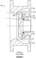
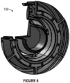
- ring disc nozzle check valve 100 comprises valve body 1 which defines valve body fluid passageways 20,22 therethrough; primary seat 2 disposed in valve body fluid passageways 20,22 proximate fluid inlet 30; primary disc 4 disposed in valve body fluid passageways 20,22 proximate fluid inlet 30 and in communication with primary seat 2; secondary disc 5 nested within valve body fluid passageways 20,22, where secondary disc 5 defines secondary seat 3 at a peripheral edge of primary disc 4; diffuser 8 disposed in the valve body fluid passageway 20 proximate fluid outlets 32a,32b; primary spring 10 disposed in valve body fluid passageways 20,22 and in communication with diffuser 8 and primary disc 4, where primary spring 10 is adapted to urge primary disc 4 to a closed position; primary shaft 6 disposed within valve body fluid passageway 22 intermediate diffuser 8 and secondary disc 5, where primary shaft 6 is in communication with diffuser 8 and adapted to support and guide primary disc 4 and allow fluid flow through primary shaft 6; secondary shaft 7 disposed within valve body fluid passageway 22 and configured
- Fluid inlet 32 is disposed axially opposite fluid outlets 32a,32b.
- Primary seat 2 typically comprises inner primary seat fluid passageway 22a in fluid communication with valve body fluid passageway 22.
- primary seat 2 comprises a first material and valve body 1 and/or secondary seat 3 comprises a second material.
- Primary disc 4 typically comprises primary disc inner diameter D1 and defines inner primary disc fluid passageway 20a in fluid communication with valve body fluid passageway 20; a closed position which typically prevents reverse fluid flow; and an open position which allows fluid flow through primary flow passage 20 when in the open position.
- primary disc 4 comprises a ring shape. In most embodiments, primary disc 4 is dimensioned to seat against valve body 1.
- Secondary disc 5 typically comprises substantially solid first end 5a comprising a diameter larger than primary disc inner diameter D 1; a closed position which typically prevents reverse fluid flow; and an open position which defines central flow passage 22 when in the open position.
- secondary disc 5 comprises a circular shape.
- secondary disc 5 is dimensioned to seat against inner diameter D2 of primary disc 4.
- inner body valve seat support 9 comprises one or more support vanes 40 which may be used to support diffuser 8 and other internal components.
- support vanes 40 are disposed proximate outlet 32a32b where they do not disrupt the flow as fluid passes over primary disc 4 and secondary disc 5.
- each of primary spring 10 and secondary spring 11 comprise a strength customized to obtain a desired opening/closing characteristic, by way of example and not limitation a customized strength that permits opening and closing of primary disc 4 and secondary disc 5 at the same time; permits primary disc 4 to open before secondary disc 5; permits secondary disc 5 to open before primary disc 4; increases a spring rate to increase dynamic performance; decreases a spring rate to decrease a minimum opening flow rate; allows operation with only one disc open of primary spring 10 and secondary spring 11; or the like; or a combination thereof.
- inner body valve seat support 9 may act as a retention ring disposed proximate fluid outlet (32a,32b) and configured to support diffuser 8.
- fluid flow may be controlled using ring disc nozzle check valve 100 by disposing ring disc nozzle check valve 100 in a fluid pathway.
- primary disc 4 and secondary disc 5 will be begin to move towards secondary seat 3 as the fluid flow rate decreases. Primary disc 4 and secondary disc 5 will continue to move towards closed position ( Fig. 1 ) as the fluid decelerates until primary disc 4 and secondary disc 5 contact seats 2 and 3, respectively.
- secondary disc 5 compresses secondary spring 11 and moves to an open position, thereby creating a low-pressure zone behind primary disc 4 which increases hydraulic force on primary disc 4 and decreases a minimum flow rate required to open ring disc nozzle valve 100.
- primary spring 10 is compressed to rest primary disc 4 in a predetermined open position. Ring disc nozzle valve 100 is maintained in the predetermined open position at fluid flow rates at or greater than the predetermined flow rate.
- primary disc 4 and secondary disc 5 move towards each disc's respective seat once the fluid reaches the full open flow rate during fluid deceleration and, if fluid flow decreases, primary disc 4 and secondary disc 5 move towards their respective closed position until primary disc 4 and secondary disc 5 contact their respective seats.
- Movement of primary disc 4 and secondary disc 5 made be via using primary spring 10 and secondary spring 11 by using secondary disc 5 to compress secondary spring 11 as secondary disc 5 moves to a fully open position and using primary disc 4 to compress primary spring 10 to rest in a predetermined fully open position once a full opening predetermined flow rate is reached.
- ring disc nozzle check valve 100 helps eliminate a need for an inner valve body seat while still maintaining a short disc stroke for fast dynamic response and allowing flow through a central passage to minimize the pressure loss across the valve.
Landscapes
- Engineering & Computer Science (AREA)
- General Engineering & Computer Science (AREA)
- Mechanical Engineering (AREA)
- Check Valves (AREA)
Claims (15)
- Ringscheiben-Düsenrückschlagventil (100), das aufweist:a. einen Ventilkörper (1), der einen Ventilkörper-Fluidkanal (20, 22) durch ihn hindurch definiert, wobei der Fluidkanal aufweist:i. einen Fluideinlass (30); undii. einen Fluidauslass (32a, 32b), der dem ersten Fluideinlass axial entgegengesetzt angeordnet ist;b. einen primären Sitz (2), der in dem Ventilkörper-Fluidkanal (20) nahe an dem Fluideinlass (30) angeordnet ist, wobei der primäre Sitz (2) einen mit dem Ventilkörper-Fluidkanal (20, 22) in Fluidverbindung stehenden inneren Fluidkanal (22a) im primären Sitz aufweist,c. eine primäre Scheibe (4), die in dem Ventilkörper-Fluidkanal nahe an dem Fluideinlass (30) und mit dem primären Sitz (2) in Verbindung angeordnet ist, wobei die primäre Scheibe aufweist:i. einen Innendurchmesser (D1) der primären Scheibe;ii. einen inneren Fluidkanal (20a) in der primären Scheibe in Fluidverbindung mit dem Ventilkörper-Fluidkanal (20, 22);iii. eine geschlossene Stellung; undiv. eine offene Stellung, die einen primären Strömungskanal (20) definiert, wenn in dem Ventilkörper-Fluidkanal (20, 22) in der offenen Stellung;d. eine sekundäre Scheibe (5), die in dem Ventilkörper-Fluidkanal (20, 22) liegend angeordnet ist, wobei die sekundäre Scheibe (5) einen sekundären Sitz (3) an einem Umfangsrand der primären Scheibe (4) definiert, wobei die sekundäre Scheibe (5) aufweist:i. ein im Wesentlichen volles erstes Ende (5a), das einen Durchmesser aufweist, der größer als der Innendurchmesser (D1) der primären Scheibe ist;ii. eine geschlossene Stellung; undiii. eine offene Stellung, die einen zentralen Strömungskanal in dem Ventilkörper-Fluidkanal definiert, wenn in der offenen Stellung;e. einen Diffusor (8), der nahe an dem Fluidauslass (32a, 32b) in dem Ventilkörper-Fluidkanal (20, 22) angeordnet ist;f. eine primäre Feder (10), die in dem Ventilkörper-Fluidkanal (20, 22) angeordnet ist und mit dem Diffusor (8) und der primären Scheibe (4) in Verbindung steht, wobei die primäre Feder zum Drängen der primären Scheibe in eine geschlossene Stellung ausgeführt ist;g. einen primären Schaft (6), der in dem Ventilkörper-Fluidkanal (20, 22) zwischen dem Diffusor (8) und der sekundären Scheibe (5) angeordnet ist, wobei der primäre Schaft mit dem Diffusor in Verbindung steht und zum Stützen und Führen der primären Scheibe und zum Ermöglichen von Fluiddurchfluss durch den primären Schaft ausgeführt ist;h. einen sekundären Schaft (7), der in dem Ventilkörper-Fluidkanal (20, 22) angeordnet ist und zum Stützen und Führen der sekundären Scheibe gestaltet ist;i. eine sekundäre Feder (11), die zwischen dem sekundären Schaft und der sekundären Scheibe angeordnet ist und zum Drängen der sekundären Scheibe in eine geschlossene Stellung gestaltet ist;j. einen Innenkörperventilsitzträger (9), der nahe an dem Fluidauslass des Ventils angeordnet ist und der gestaltet ist, um den Fluiddurchfluss im Ventilkörper (1) beim Strömen des Fluids über die primäre Scheibe, die sekundäre Scheibe oder sowohl die primäre Scheibe als auch die sekundäre Scheibe nicht zu stören; undk. ein Befestigungselement (12), das zum Befestigen des Innenkörperventilsitzträgers (9) am Ventilkörper (1) gestaltet ist.
- Ringscheiben-Düsenrückschlagventil nach Anspruch 1, wobei der Innenkörperventilsitzträger ein Unterstützungsleitelement (40) aufweist.
- Ringscheiben-Düsenrückschlagventil nach Anspruch 1, wobei:a. die primäre Scheibe eine Ringform aufweist; undb. die sekundäre Scheibe eine Kreisform aufweist.
- Ringscheiben-Düsenrückschlagventil nach Anspruch 1, wobei:a. die primäre Scheibe zum Anliegen am Ventilkörper dimensioniert ist; undb. die sekundäre Scheibe zum Anliegen am Innendurchmesser der primären Scheibe dimensioniert ist.
- Ringscheiben-Düsenrückschlagventil nach Anspruch 1, wobei der primäre Sitz (2) ein erstes Material aufweist und der Ventilkörper (1) ein zweites Material aufweist.
- Ringscheiben-Düsenrückschlagventil nach Anspruch 1, wobei die primäre Scheibe (4) ein erstes Material aufweist und der sekundäre Sitz (5) ein zweites Material aufweist.
- Ringscheiben-Düsenrückschlagventil nach Anspruch 1, wobei der Innenkörperventilsitzträger (9), der als Haltering wirkt, der nahe an dem Fluidauslass (32a, 32b) angeordnet ist, ferner zum Stützen des Diffusors (8) gestaltet ist.
- Ringscheiben-Düsenrückschlagventil nach Anspruch 1, wobei die primäre Scheibe in ihrer geschlossenen Stellung Fluidrückfluss verhindert.
- Ringscheiben-Düsenrückschlagventil nach Anspruch 1, wobei die sekundäre Scheibe in ihrer geschlossenen Stellung Fluidrückfluss verhindert.
- Ringscheiben-Düsenrückschlagventil nach Anspruch 1, wobei die primäre Feder und die sekundäre Feder jeweils eine Stärke aufweisen, die spezifisch zum Erhalten einer erwünschten Öffnungs-/Schließcharakteristik ausgeführt ist; und, wahlweise,
wobei die spezifisch ausgeführte Stärke eine Stärke aufweist, die:a. Öffnen und Schließen der primären Scheibe und gleichzeitig der sekundären Scheibe zulässt;b. das Öffnen der primären Scheibe vor der sekundären Scheibe zulässt;c. das Öffnen der sekundären Scheibe vor der primären Scheibe zulässt;d. eine Federkonstante zum Erhöhen der dynamischen Leistung erhöht;e. eine Federkonstante zum Verringern einer Mindestöffnungsdurchflussrate verringert; oderf. den Betrieb mit nur einer Scheibe in offener Stellung ermöglicht. - Verfahren zum Regeln von Fluiddurchfluss unter Verwendung eines Ringscheiben-Düsenrückschlagventils (100), das einen Ventilkörper (1) aufweist, der einen Ventilkörper-Fluidkanal (20, 22) durch ihn hindurch definiert, wobei der Fluidkanal aufweist: einen Fluideinlass (30) und einen Fluidauslass (32a, 32b), der dem ersten Fluideinlass axial entgegengesetzt angeordnet ist; einen primären Sitz (2), der in dem Ventilkörper-Fluidkanal (20) nahe an dem Fluideinlass (30) angeordnet ist, wobei der primäre Sitz (2) einen mit dem Ventilkörper-Fluidkanal (20, 22) in Fluidverbindung stehenden inneren Fluidkanal (22a) im primären Sitz aufweist; eine primäre Scheibe (4), die in dem Ventilkörper-Fluidkanal nahe an dem Fluideinlass (30) und mit dem primären Sitz (2) in Verbindung angeordnet ist, wobei die primäre Scheibe aufweist: einen Innendurchmesser (D1) der primären Scheibe; einen inneren Fluidkanal (20a) in der primären Scheibe in Fluidverbindung mit dem Ventilkörper-Fluidkanal (20, 22), eine geschlossene Stellung und eine offene Stellung, die einen primären Strömungskanal (20) definiert, wenn in dem Ventilkörper-Fluidkanal (20, 22) in der offenen Stellung; eine sekundäre Scheibe (5), die in dem Ventilkörper-Fluidkanal (20, 22) verschachtelt ist, wobei die sekundäre Scheibe (5) einen sekundären Sitz (3) an einem Umfangsrand der primären Scheibe (4) definiert, wobei die zweite Scheibe ein im Wesentlichen volles erstes Ende (5a), das einen Durchmesser aufweist, der größer als der Innendurchmesser (D1) der primären Scheibe ist, eine geschlossene Stellung und eine offene Stellung, die einen zentralen Strömungskanal in dem Ventilkörper-Fluidkanal definiert, wenn in der offenen Stellung; einen Diffusor (8), der nahe an dem Fluidauslass (32a, 32b) in dem Ventilkörper-Fluidkanal (20, 22) angeordnet ist; eine primäre Feder (10), die in dem Ventilkörper-Fluidkanal (20, 22) angeordnet ist und mit dem Diffusor (8) und der primären Scheibe (4) in Verbindung steht, wobei die primäre Feder zum Drängen der primären Scheibe in eine geschlossene Stellung ausgeführt ist; einen primären Schaft (6), der in dem Ventilkörper-Fluidkanal (20, 22) zwischen dem Diffusor (8) und der sekundären Scheibe (5) angeordnet ist, wobei der primäre Schaft mit dem Diffusor in Verbindung steht und zum Stützen und Führen der primären Scheibe und zum Ermöglichen von Fluiddurchfluss durch den primären Schaft ausgeführt ist; einen sekundären Schaft (7), der in dem Ventilkörper-Fluidkanal (20, 22) angeordnet ist und zum Stützen und Führen der sekundären Scheibe gestaltet ist; eine sekundäre Feder (11), die zwischen dem sekundären Schaft und der sekundären Scheibe angeordnet ist und zum Drängen der sekundären Scheibe in eine geschlossene Stellung gestaltet ist; einen Innenkörperventilsitzträger (9), der nahe an dem Fluidauslass des Ventils angeordnet ist und gestaltet ist, um den Fluiddurchfluss im Ventilkörper (1) beim Strömen des Fluids über die primäre Scheibe und/oder die sekundäre Scheibe nicht zu stören; und ein Befestigungselement (12), das zum Befestigen des Innenkörperventilsitzträgers (9) am Ventilkörper (1) gestaltet ist,
wobei das Verfahren aufweist:a. Anordnen des Ringscheiben-Düsenrückschlagventils (100) in einem Fluidkanal;b. beim Beschleunigen des Fluiddurchflusses in dem Fluidkanal Ermöglichen, dass die sekundäre Scheibe die sekundäre Feder zusammendrückt und sich in eine offene Stellung bewegt, wodurch hinter der primären Scheibe eine Niedrigdruckzone hergestellt wird, die die auf die primäre Scheibe wirkende hydraulische Kraft erhöht und eine Mindestdurchflussrate verringert, die zum Öffnen des Ringscheiben-Düsenventils erforderlich ist;c. sobald eine vorbestimmte Durchflussrate erreicht worden ist, Zusammendrücken der primären Feder, um die primäre Scheibe in einer vorbestimmten offenen Stellung ruhen zu lassen; undd. Halten des Ringscheiben-Düsenventils bei Fluiddurchflussraten, die so groß wie die vorbestimmte Durchflussrate oder größer sind, in der vorbestimmten offenen Stellung. - Verfahren zum Regeln von Fluiddurchfluss nach Anspruch 11, das ferner aufweist:a. wenn der Fluiddurchfluss verringert wird, Ermöglichen, dass sich die primäre Scheibe und die sekundäre Scheibe bei Verlangsamung der Fluiddurchflussrate in Richtung auf den jeweiligen Sitz jeder Scheibe bewegen; undb. Ermöglichen, dass sich die primäre Scheibe und die sekundäre Scheibe bei Verlangsamung des Fluids weiter in Richtung auf ihre jeweilige geschlossene Stellung bewegen, bis die primäre Scheibe und die sekundäre Scheibe mit ihrem jeweiligen Sitz in Kontakt kommen.
- Verfahren nach Anspruch 11, das ferner weiteres Regeln der Scheibenbewegung unter Verwendung der primären Feder und der sekundären Feder aufweist, wobei das Verfahren ferner aufweist:a. Verwenden der sekundären Scheibe zum Zusammendrücken der sekundären Feder beim Bewegen der sekundären Scheibe in eine ganz offene Stellung; undb. Verwenden der primären Scheibe zum Zusammendrücken der primären Feder zum Ruhen in einer vorbestimmten ganz offenen Stellung, sobald eine vorbestimmte Durchflussrate für die volle Öffnung erreicht worden ist.
- Verfahren nach Anspruch 11, wobei das Herstellen der Niedrigdruckzone hinter der primären Scheibe aufgrund einer Form des sekundären Strömungskanals stattfindet.
- Verfahren nach Anspruch 11, wobei das Ringscheiben-Düsenventil bei Durchflussraten, die so groß wie die vorbestimmte Durchflussrate oder größer sind, in einer ganz offenen Stellung gehalten wird.
Applications Claiming Priority (2)
| Application Number | Priority Date | Filing Date | Title |
|---|---|---|---|
| US201962845042P | 2019-05-08 | 2019-05-08 | |
| PCT/US2020/032094 WO2020227628A1 (en) | 2019-05-08 | 2020-05-08 | Dual disc non-slam nozzle check valve |
Publications (3)
| Publication Number | Publication Date |
|---|---|
| EP3966478A1 EP3966478A1 (de) | 2022-03-16 |
| EP3966478A4 EP3966478A4 (de) | 2023-01-18 |
| EP3966478B1 true EP3966478B1 (de) | 2024-10-16 |
Family
ID=73047015
Family Applications (1)
| Application Number | Title | Priority Date | Filing Date |
|---|---|---|---|
| EP20801806.9A Active EP3966478B1 (de) | 2019-05-08 | 2020-05-08 | Düsenrückschlagventil mit zwei scheiben |
Country Status (3)
| Country | Link |
|---|---|
| US (1) | US11236837B2 (de) |
| EP (1) | EP3966478B1 (de) |
| WO (1) | WO2020227628A1 (de) |
Families Citing this family (1)
| Publication number | Priority date | Publication date | Assignee | Title |
|---|---|---|---|---|
| CN117028626A (zh) * | 2023-08-22 | 2023-11-10 | 江苏神通核能装备有限公司 | 一种高温高压微压启闭升降式止回阀 |
Family Cites Families (17)
| Publication number | Priority date | Publication date | Assignee | Title |
|---|---|---|---|---|
| US2304991A (en) * | 1940-09-13 | 1942-12-15 | Emsco Derrick & Equip Co | Valve pot |
| US3856041A (en) * | 1973-11-28 | 1974-12-24 | Caterpillar Tractor Co | Combination relief and make-up valve |
| US4420010A (en) * | 1978-03-28 | 1983-12-13 | Amtrol Inc. | In-line back flow preventer |
| GB0004360D0 (en) * | 2000-02-25 | 2000-04-12 | Imi Norgren Ltd | Valve |
| US6443183B1 (en) * | 2000-06-07 | 2002-09-03 | Transcend Inc. | Valve and assembly for axially movable members |
| US6374852B1 (en) * | 2000-08-09 | 2002-04-23 | Brightvalve, Llc | Leak arresting valve |
| JP4035022B2 (ja) * | 2002-09-11 | 2008-01-16 | 本田技研工業株式会社 | 蒸発燃料処理装置 |
| US7114516B2 (en) * | 2002-10-15 | 2006-10-03 | Takasago Engineering Co., Ltd. | Leak-detecting check valve, and leak-detection alarm system that uses said check valve |
| US20100101668A1 (en) * | 2008-10-28 | 2010-04-29 | Oene Roorda | Check Valve |
| EP2405163B2 (de) * | 2010-07-08 | 2018-08-08 | Cameron International Corporation | Düsenrückschlagventil |
| US8701693B2 (en) * | 2010-12-23 | 2014-04-22 | Curtiss-Wright Flow Control Corp | Nozzle check valve |
| DE102011005106A1 (de) * | 2011-02-18 | 2012-08-23 | Hengst Gmbh & Co. Kg | Umgehungsventil, Einrichtung mit Umgehungsventil und Filtereinsatz der Einrichtung |
| GB2535715B (en) * | 2015-02-24 | 2017-02-15 | Goodwin Plc | Nozzle check valve |
| US20170108131A1 (en) * | 2015-10-20 | 2017-04-20 | Flomatic Corporation | Check valve |
| JP6760176B2 (ja) * | 2017-03-29 | 2020-09-23 | 株式会社豊田自動織機 | 圧縮機 |
| DE102017007458A1 (de) * | 2017-08-08 | 2019-02-14 | Honeywell Technologies Sarl | Sicherungsarmatur |
| US10844965B2 (en) * | 2018-10-22 | 2020-11-24 | Mueller International, Llc | Anti-shock check valve |
-
2020
- 2020-05-08 EP EP20801806.9A patent/EP3966478B1/de active Active
- 2020-05-08 WO PCT/US2020/032094 patent/WO2020227628A1/en not_active Ceased
- 2020-05-08 US US16/870,318 patent/US11236837B2/en active Active
Also Published As
| Publication number | Publication date |
|---|---|
| US20200355283A1 (en) | 2020-11-12 |
| WO2020227628A1 (en) | 2020-11-12 |
| US11236837B2 (en) | 2022-02-01 |
| EP3966478A4 (de) | 2023-01-18 |
| EP3966478A1 (de) | 2022-03-16 |
Similar Documents
| Publication | Publication Date | Title |
|---|---|---|
| EP3056739B1 (de) | Entlüftungsventil des hülsentyps, betätigt durch zwei steuerdrücke, die auf ein kolben wirken | |
| US4137933A (en) | Control valve | |
| US9611948B1 (en) | Valve assembly | |
| CN113661465B (zh) | 具有切断机构的减压阀 | |
| US4116212A (en) | Unidirectional flow control valve | |
| JP5966094B2 (ja) | ソレノイドバルブ | |
| US4537384A (en) | In-line check valve having combined downstream poppet support and flow control elements | |
| US3583431A (en) | Pressure relief valve | |
| US10731771B2 (en) | Flow limiter valve | |
| US20170108131A1 (en) | Check valve | |
| EP3748209B1 (de) | Strömungsmaximierung | |
| EP1509714B1 (de) | Druckregelventil | |
| CN205908824U (zh) | 调节阀和用于调节阀的平衡阀内件 | |
| US11236837B2 (en) | Dual disc non-slam nozzle check valve | |
| CN112648248B (zh) | 一种速控单向阀 | |
| EP2580504B1 (de) | Ringförmiges flächendichtungsventil für eine strömungsmaschine | |
| US4432389A (en) | Reseat relief valve | |
| CN110869657B (zh) | 可变流量提升阀 | |
| RU2660745C1 (ru) | Клапан обратный | |
| US4316478A (en) | Fluid control valve | |
| US9500171B2 (en) | Pressure regulating valve | |
| US4205696A (en) | Fluid control valve | |
| US3318326A (en) | Relief valve | |
| US3883265A (en) | Turbine | |
| JP2005307972A (ja) | 流体用レギュレータ |
Legal Events
| Date | Code | Title | Description |
|---|---|---|---|
| STAA | Information on the status of an ep patent application or granted ep patent |
Free format text: STATUS: THE INTERNATIONAL PUBLICATION HAS BEEN MADE |
|
| PUAI | Public reference made under article 153(3) epc to a published international application that has entered the european phase |
Free format text: ORIGINAL CODE: 0009012 |
|
| STAA | Information on the status of an ep patent application or granted ep patent |
Free format text: STATUS: REQUEST FOR EXAMINATION WAS MADE |
|
| 17P | Request for examination filed |
Effective date: 20210924 |
|
| AK | Designated contracting states |
Kind code of ref document: A1 Designated state(s): AL AT BE BG CH CY CZ DE DK EE ES FI FR GB GR HR HU IE IS IT LI LT LU LV MC MK MT NL NO PL PT RO RS SE SI SK SM TR |
|
| DAV | Request for validation of the european patent (deleted) | ||
| DAX | Request for extension of the european patent (deleted) | ||
| A4 | Supplementary search report drawn up and despatched |
Effective date: 20221216 |
|
| RIC1 | Information provided on ipc code assigned before grant |
Ipc: F16K 39/02 20060101ALI20221212BHEP Ipc: F16K 17/04 20060101ALI20221212BHEP Ipc: F16K 15/06 20060101ALI20221212BHEP Ipc: F16K 47/00 20060101ALI20221212BHEP Ipc: F16K 31/00 20060101ALI20221212BHEP Ipc: F16K 17/00 20060101ALI20221212BHEP Ipc: F16K 15/00 20060101ALI20221212BHEP Ipc: F16K 1/00 20060101AFI20221212BHEP |
|
| P01 | Opt-out of the competence of the unified patent court (upc) registered |
Effective date: 20230526 |
|
| GRAP | Despatch of communication of intention to grant a patent |
Free format text: ORIGINAL CODE: EPIDOSNIGR1 |
|
| STAA | Information on the status of an ep patent application or granted ep patent |
Free format text: STATUS: GRANT OF PATENT IS INTENDED |
|
| INTG | Intention to grant announced |
Effective date: 20240517 |
|
| GRAS | Grant fee paid |
Free format text: ORIGINAL CODE: EPIDOSNIGR3 |
|
| GRAA | (expected) grant |
Free format text: ORIGINAL CODE: 0009210 |
|
| STAA | Information on the status of an ep patent application or granted ep patent |
Free format text: STATUS: THE PATENT HAS BEEN GRANTED |
|
| RAP3 | Party data changed (applicant data changed or rights of an application transferred) |
Owner name: OCEANEERING INTERNATIONAL, INC. |
|
| AK | Designated contracting states |
Kind code of ref document: B1 Designated state(s): AL AT BE BG CH CY CZ DE DK EE ES FI FR GB GR HR HU IE IS IT LI LT LU LV MC MK MT NL NO PL PT RO RS SE SI SK SM TR |
|
| REG | Reference to a national code |
Ref country code: GB Ref legal event code: FG4D |
|
| REG | Reference to a national code |
Ref country code: CH Ref legal event code: EP Ref country code: DE Ref legal event code: R096 Ref document number: 602020039621 Country of ref document: DE |
|
| REG | Reference to a national code |
Ref country code: IE Ref legal event code: FG4D |
|
| REG | Reference to a national code |
Ref country code: LT Ref legal event code: MG9D |
|
| REG | Reference to a national code |
Ref country code: NL Ref legal event code: MP Effective date: 20241016 |
|
| REG | Reference to a national code |
Ref country code: AT Ref legal event code: MK05 Ref document number: 1733149 Country of ref document: AT Kind code of ref document: T Effective date: 20241016 |
|
| PG25 | Lapsed in a contracting state [announced via postgrant information from national office to epo] |
Ref country code: NL Free format text: LAPSE BECAUSE OF FAILURE TO SUBMIT A TRANSLATION OF THE DESCRIPTION OR TO PAY THE FEE WITHIN THE PRESCRIBED TIME-LIMIT Effective date: 20241016 |
|
| PG25 | Lapsed in a contracting state [announced via postgrant information from national office to epo] |
Ref country code: NL Free format text: LAPSE BECAUSE OF FAILURE TO SUBMIT A TRANSLATION OF THE DESCRIPTION OR TO PAY THE FEE WITHIN THE PRESCRIBED TIME-LIMIT Effective date: 20241016 |
|
| PG25 | Lapsed in a contracting state [announced via postgrant information from national office to epo] |
Ref country code: PT Free format text: LAPSE BECAUSE OF FAILURE TO SUBMIT A TRANSLATION OF THE DESCRIPTION OR TO PAY THE FEE WITHIN THE PRESCRIBED TIME-LIMIT Effective date: 20250217 Ref country code: HR Free format text: LAPSE BECAUSE OF FAILURE TO SUBMIT A TRANSLATION OF THE DESCRIPTION OR TO PAY THE FEE WITHIN THE PRESCRIBED TIME-LIMIT Effective date: 20241016 Ref country code: IS Free format text: LAPSE BECAUSE OF FAILURE TO SUBMIT A TRANSLATION OF THE DESCRIPTION OR TO PAY THE FEE WITHIN THE PRESCRIBED TIME-LIMIT Effective date: 20250216 |
|
| PG25 | Lapsed in a contracting state [announced via postgrant information from national office to epo] |
Ref country code: FI Free format text: LAPSE BECAUSE OF FAILURE TO SUBMIT A TRANSLATION OF THE DESCRIPTION OR TO PAY THE FEE WITHIN THE PRESCRIBED TIME-LIMIT Effective date: 20241016 |
|
| PG25 | Lapsed in a contracting state [announced via postgrant information from national office to epo] |
Ref country code: BG Free format text: LAPSE BECAUSE OF FAILURE TO SUBMIT A TRANSLATION OF THE DESCRIPTION OR TO PAY THE FEE WITHIN THE PRESCRIBED TIME-LIMIT Effective date: 20241016 |
|
| PG25 | Lapsed in a contracting state [announced via postgrant information from national office to epo] |
Ref country code: ES Free format text: LAPSE BECAUSE OF FAILURE TO SUBMIT A TRANSLATION OF THE DESCRIPTION OR TO PAY THE FEE WITHIN THE PRESCRIBED TIME-LIMIT Effective date: 20241016 |
|
| PG25 | Lapsed in a contracting state [announced via postgrant information from national office to epo] |
Ref country code: LV Free format text: LAPSE BECAUSE OF FAILURE TO SUBMIT A TRANSLATION OF THE DESCRIPTION OR TO PAY THE FEE WITHIN THE PRESCRIBED TIME-LIMIT Effective date: 20241016 Ref country code: AT Free format text: LAPSE BECAUSE OF FAILURE TO SUBMIT A TRANSLATION OF THE DESCRIPTION OR TO PAY THE FEE WITHIN THE PRESCRIBED TIME-LIMIT Effective date: 20241016 Ref country code: GR Free format text: LAPSE BECAUSE OF FAILURE TO SUBMIT A TRANSLATION OF THE DESCRIPTION OR TO PAY THE FEE WITHIN THE PRESCRIBED TIME-LIMIT Effective date: 20250117 |
|
| PG25 | Lapsed in a contracting state [announced via postgrant information from national office to epo] |
Ref country code: PL Free format text: LAPSE BECAUSE OF FAILURE TO SUBMIT A TRANSLATION OF THE DESCRIPTION OR TO PAY THE FEE WITHIN THE PRESCRIBED TIME-LIMIT Effective date: 20241016 |
|
| PG25 | Lapsed in a contracting state [announced via postgrant information from national office to epo] |
Ref country code: RS Free format text: LAPSE BECAUSE OF FAILURE TO SUBMIT A TRANSLATION OF THE DESCRIPTION OR TO PAY THE FEE WITHIN THE PRESCRIBED TIME-LIMIT Effective date: 20250116 |
|
| PG25 | Lapsed in a contracting state [announced via postgrant information from national office to epo] |
Ref country code: SM Free format text: LAPSE BECAUSE OF FAILURE TO SUBMIT A TRANSLATION OF THE DESCRIPTION OR TO PAY THE FEE WITHIN THE PRESCRIBED TIME-LIMIT Effective date: 20241016 |
|
| PG25 | Lapsed in a contracting state [announced via postgrant information from national office to epo] |
Ref country code: DK Free format text: LAPSE BECAUSE OF FAILURE TO SUBMIT A TRANSLATION OF THE DESCRIPTION OR TO PAY THE FEE WITHIN THE PRESCRIBED TIME-LIMIT Effective date: 20241016 |
|
| PGFP | Annual fee paid to national office [announced via postgrant information from national office to epo] |
Ref country code: GB Payment date: 20250522 Year of fee payment: 6 |
|
| PGFP | Annual fee paid to national office [announced via postgrant information from national office to epo] |
Ref country code: NO Payment date: 20250528 Year of fee payment: 6 |
|
| REG | Reference to a national code |
Ref country code: DE Ref legal event code: R097 Ref document number: 602020039621 Country of ref document: DE |
|
| PG25 | Lapsed in a contracting state [announced via postgrant information from national office to epo] |
Ref country code: EE Free format text: LAPSE BECAUSE OF FAILURE TO SUBMIT A TRANSLATION OF THE DESCRIPTION OR TO PAY THE FEE WITHIN THE PRESCRIBED TIME-LIMIT Effective date: 20241016 |
|
| PG25 | Lapsed in a contracting state [announced via postgrant information from national office to epo] |
Ref country code: RO Free format text: LAPSE BECAUSE OF FAILURE TO SUBMIT A TRANSLATION OF THE DESCRIPTION OR TO PAY THE FEE WITHIN THE PRESCRIBED TIME-LIMIT Effective date: 20241016 |
|
| PG25 | Lapsed in a contracting state [announced via postgrant information from national office to epo] |
Ref country code: SK Free format text: LAPSE BECAUSE OF FAILURE TO SUBMIT A TRANSLATION OF THE DESCRIPTION OR TO PAY THE FEE WITHIN THE PRESCRIBED TIME-LIMIT Effective date: 20241016 |
|
| PG25 | Lapsed in a contracting state [announced via postgrant information from national office to epo] |
Ref country code: CZ Free format text: LAPSE BECAUSE OF FAILURE TO SUBMIT A TRANSLATION OF THE DESCRIPTION OR TO PAY THE FEE WITHIN THE PRESCRIBED TIME-LIMIT Effective date: 20241016 |
|
| PG25 | Lapsed in a contracting state [announced via postgrant information from national office to epo] |
Ref country code: IT Free format text: LAPSE BECAUSE OF FAILURE TO SUBMIT A TRANSLATION OF THE DESCRIPTION OR TO PAY THE FEE WITHIN THE PRESCRIBED TIME-LIMIT Effective date: 20241016 |
|
| PLBE | No opposition filed within time limit |
Free format text: ORIGINAL CODE: 0009261 |
|
| STAA | Information on the status of an ep patent application or granted ep patent |
Free format text: STATUS: NO OPPOSITION FILED WITHIN TIME LIMIT |
|
| PG25 | Lapsed in a contracting state [announced via postgrant information from national office to epo] |
Ref country code: SE Free format text: LAPSE BECAUSE OF FAILURE TO SUBMIT A TRANSLATION OF THE DESCRIPTION OR TO PAY THE FEE WITHIN THE PRESCRIBED TIME-LIMIT Effective date: 20241016 |
|
| 26N | No opposition filed |
Effective date: 20250717 |
|
| REG | Reference to a national code |
Ref country code: DE Ref legal event code: R119 Ref document number: 602020039621 Country of ref document: DE |
|
| REG | Reference to a national code |
Ref country code: CH Ref legal event code: H13 Free format text: ST27 STATUS EVENT CODE: U-0-0-H10-H13 (AS PROVIDED BY THE NATIONAL OFFICE) Effective date: 20251223 |
|
| PG25 | Lapsed in a contracting state [announced via postgrant information from national office to epo] |
Ref country code: LU Free format text: LAPSE BECAUSE OF NON-PAYMENT OF DUE FEES Effective date: 20250508 |
|
| PG25 | Lapsed in a contracting state [announced via postgrant information from national office to epo] |
Ref country code: CH Free format text: LAPSE BECAUSE OF NON-PAYMENT OF DUE FEES Effective date: 20250531 |
|
| REG | Reference to a national code |
Ref country code: BE Ref legal event code: MM Effective date: 20250531 |
|
| PG25 | Lapsed in a contracting state [announced via postgrant information from national office to epo] |
Ref country code: MC Free format text: LAPSE BECAUSE OF FAILURE TO SUBMIT A TRANSLATION OF THE DESCRIPTION OR TO PAY THE FEE WITHIN THE PRESCRIBED TIME-LIMIT Effective date: 20241016 |
|
| PG25 | Lapsed in a contracting state [announced via postgrant information from national office to epo] |
Ref country code: IE Free format text: LAPSE BECAUSE OF NON-PAYMENT OF DUE FEES Effective date: 20250508 Ref country code: DE Free format text: LAPSE BECAUSE OF NON-PAYMENT OF DUE FEES Effective date: 20251202 |
|
| PG25 | Lapsed in a contracting state [announced via postgrant information from national office to epo] |
Ref country code: BE Free format text: LAPSE BECAUSE OF NON-PAYMENT OF DUE FEES Effective date: 20250531 |
|
| PG25 | Lapsed in a contracting state [announced via postgrant information from national office to epo] |
Ref country code: FR Free format text: LAPSE BECAUSE OF NON-PAYMENT OF DUE FEES Effective date: 20250531 |