EP3966090B1 - Sattelschlepperfahrzeug mit einer sattelkupplung - Google Patents
Sattelschlepperfahrzeug mit einer sattelkupplung Download PDFInfo
- Publication number
- EP3966090B1 EP3966090B1 EP20725964.9A EP20725964A EP3966090B1 EP 3966090 B1 EP3966090 B1 EP 3966090B1 EP 20725964 A EP20725964 A EP 20725964A EP 3966090 B1 EP3966090 B1 EP 3966090B1
- Authority
- EP
- European Patent Office
- Prior art keywords
- mounting plate
- bolts
- towing vehicle
- diameter
- holes
- Prior art date
- Legal status (The legal status is an assumption and is not a legal conclusion. Google has not performed a legal analysis and makes no representation as to the accuracy of the status listed.)
- Active
Links
Images


Classifications
-
- B—PERFORMING OPERATIONS; TRANSPORTING
- B62—LAND VEHICLES FOR TRAVELLING OTHERWISE THAN ON RAILS
- B62D—MOTOR VEHICLES; TRAILERS
- B62D53/00—Tractor-trailer combinations; Road trains
- B62D53/04—Tractor-trailer combinations; Road trains comprising a vehicle carrying an essential part of the other vehicle's load by having supporting means for the front or rear part of the other vehicle
- B62D53/08—Fifth wheel traction couplings
- B62D53/0807—Fifth wheel traction couplings adjustable coupling saddles mounted on sub-frames; Mounting plates therefor
Definitions
- the invention relates to a semitrailer towing vehicle comprising a fifth wheel assembly comprising bearing blocks and a fifth wheel plate which is mounted on the bearing blocks such that it can pivot about an axis extending transversely to the direction of travel, the bearing blocks being fastened to a corrugated mounting plate, said corrugated mounting plate being attached to a chassis of the semitrailer towing vehicle, said corrugated mounting plate having upper portions and lower portions, the distance between the upper and lower portions defining a height of the corrugated mounting plate, the upper portions being positioned closer to the fifth wheel plate than the lower portions, the bearing blocks being fastened to the corrugated mounting plate by bolts which pass through first holes provided in the bearing blocks and second holes provided in the corrugated mounting plate.
- Such a semitrailer towing vehicle comprising a fifth wheel assembly is e.g. known from EP0538893B1 .
- the semitrailer towing vehicle according to EP0538893B1 comprises a height adapter between the bearing blocks and the corrugated mounting plate.
- the first holes in the bearing blocks and the second holes in the mounting plate are oversized in comparison to the bolts.
- an object of the invention to provide a semitrailer towing vehicle comprising a fifth wheel assembly having a relatively small constructional height. It is another object of the invention to provide a semitrailer towing vehicle comprising a fifth wheel assembly having a relatively simple construction. It is a further object of the invention to provide an alternative semitrailer towing vehicle comprising a fifth wheel assembly.
- a semitrailer towing vehicle comprising a fifth wheel assembly comprising bearing blocks and a fifth wheel plate which is mounted on the bearing blocks such that it can pivot about an axis extending transversely to the direction of travel, the bearing blocks being fastened to a corrugated mounting plate, said corrugated mounting plate being attached to a chassis of the semitrailer towing vehicle, said corrugated mounting plate having upper portions and lower portions, the distance between the upper and lower portions defining a height of the corrugated mounting plate, the upper portions being positioned closer to the fifth wheel plate than the lower portions, the bearing blocks being fastened to the corrugated mounting plate by bolts which pass through first holes provided in the bearing blocks and second holes provided in the corrugated mounting plate, characterized in that the bolts have a head height of 0.25 - 0.4 times the shank diameter of the bolts, in that the head height of the bolts is smaller than the height of the corrugated mounting plate and in that the heads of the bolts engage a
- the constructional height measured from the lower surface of the lower portions of the corrugated mounting plate to the upper surface of the fifth wheel plate can be reduced in comparison to EP0538893B1 since amongst other things the height of the corrugated mounting plate can be reduced.
- the height of the corrugated mounting plate can be very small while it is still possible that the head of the bolts can be accommodated in the space defined by the height of the corrugated mounting plate.
- the first holes provided in the bearing blocks are elongated holes, each having a first short diameter in transverse direction and a first long diameter in longitudinal direction, said first long diameter being larger than the first short diameter, the second holes in the corrugated mounting plate being circular and having a uniform second diameter.
- the first short diameter of the first holes in the bearing blocks is equal to the second diameter of the second holes in the corrugated mounting plate.
- the first long diameter is larger than the first short diameter, i.e. the first holes in the bearing blocks are oversized in the longitudinal direction in comparison to the bolts it is prevented that shear forces in this direction act on the bolts.
- the first short diameter is 18 mm.
- the bolts have a uniform shank diameter.
- Bolts having a uniform shank diameter can be manufactured relatively easily, and in particular when the shank of the bolts have a diameter such that the shank of the bolts tightly fits in the transverse direction of the elongated holes provided in the bearing blocks of the fifth wheel assembly, i.e.
- the diameter of the shank matches the first short diameter, in contrast to the construction of EP0538893B1 in which the bolts loosely fit in the first holes of the bearing blocks, the shear forces generated in transverse direction during operation of the fifth wheel directly act on the bolts as a result of which it is possible to dispense of the thrust plates used in EP0538893B1 , thereby making the construction of the semitrailer towing vehicle comprising a fifth wheel assembly relatively simple.
- the construction of the fifth wheel has sufficient strength amongst other things as a result of the holes being circular and that the bolts are in engagement in transverse direction with the inner surface of the first holes in the bearing blocks as a result of the tight fit.
- the head of the bolt comprises a flange having a diameter larger than a diameter of the head.
- the bolts have a ribbed neck, the ribbed neck at least engaging an inside of a second hole in the corrugated mounting plate.
- the first short diameter of the first holes in the bearing blocks is smaller than the second diameter of the second holes in the corrugated mounting plate, .
- the bolts having a circular neck adjacent the head, the circular neck having a neck diameter such that the circular neck of the bolts fits in the second holes provided in the corrugated mounting plate, and that the height of the circular neck is smaller than a thickness of the corrugated mounting plate.
- the second diameter of the second holes is 23 mm and the neck diameter of the bolts is 21 mm.
- the shank of the bolts have a diameter such that the shank of the bolts tightly fits in the transverse direction of the elongated holes provided in the bearing blocks of the fifth wheel assembly.
- the shear forces generated during operation of the fifth wheel in the transverse direction now act on the bolts as a result of the tight fit, which makes it possible to dispense of the thrust plates used in EP0538893B1 , thereby making the construction of the semitrailer towing vehicle comprising a fifth wheel assembly relatively simple.
- the bolts are M16 bolts, in particular 10.9 grade bolts are sufficiently strong to withstand the shear forces generated during operation of the semitrailer towing vehicle.
- the corrugated mounting plate is made of S600MC and has a thickness of between 3 and 9 mm, preferably the corrugated mounting plate has a thickness of 6 mm.
- the corrugated mounting plate preferably has a weight of 30 kg or less.
- the total weight of the semitrailer towing vehicle comprising a fifth wheel assembly is reduced thereby providing a possibility to reduce the usage of fuel during operation of the semitrailer towing vehicle.
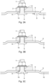
- FIG. 1 an embodiment of a semitrailer towing vehicle comprising a fifth wheel assembly 1 according to the invention is schematically shown in cross section.
- the fifth wheel assembly 1 comprises bearing blocks 2, 3 and a fifth wheel plate 4 mounted on the bearing blocks 2, 3.
- the fifth wheel plate 4 is mounted in such manner on the bearing blocks 2, 3 that it can pivot about an axis extending transversely to the direction of travel as is known in the art. Please note that throughout this description the same reference numerals are used for indicating identical parts.
- the bearing blocks 2, 3 are fastened to a corrugated mounting plate 5 by means of bolt and nut elements 6, 7.
- the corrugated mounting plate 4 is attached to a chassis 8 of the semitrailer towing vehicle.
- the corrugated mounting plate 5 has upper portions 9 and lower portions 10, which lower portions 10 are in contact with the chassis 8.
- the distance H (see Figure 3A ) between the upper portions 9 and lower portions 10 define the height H of the corrugated mounting plate 5.
- the upper portions 9 are positioned closer to the fifth wheel plate 4 than the lower portions 10.
- the bearing blocks 2, 3 are fastened to the corrugated mounting plate 5 by bolts 11, 12 which pass through first holes 13 (see Figures 3 ) provided in the bearing blocks 2 and second holes 14 provided in the corrugated mounting plate 5.
- the first holes 13 provided in the bearing blocks 2, 3 are elongated holes as shown in Figure 5 .
- Each first hole 13 has a first short diameter 13A in transverse direction and a first long diameter 13B in longitudinal direction of the elongated first hole 13.
- the first long diameter 13B is larger than the first short diameter 13A.
- the first short diameter 13A is 18 mm.
- the second holes 14 in the corrugated mounting plate 5 are circular and have a uniform second diameter.
- the second diameter of the second holes 14 can be identical to the first short diameter 13A of the first holes 13 (as shown in the embodiments of Figures 3A and 3B ) or can be larger (as shown in the embodiment of Figure 3C ) than the first short diameter 13A of the first holes 13. In this latter embodiment the second diameter of the second holes 14 is 23 mm.
- the diameter of the shanks 15 of the bolts 11 is such that the shanks 15 of the bolts 11 tightly fit in the transverse direction of the elongated first holes 13 provided in the bearing blocks 2, 3 as indicated in Figures 3A-C , that is the diameter of the shanks 15 of the bolts 11 matches the first short diameter 13A.
- the height of the heads 16 of the bolts 11 is 0.25 - 0.4 times the shank diameter of the bolts 11, and the bolts are therefore herein also called low head bolts.
- the head height of the bolts 11 is smaller than the height H of the corrugated mounting plate 5 and since the heads 16 of the bolts 11 engage a lower surface L (positioned opposite the fifth wheel plate 4) of an upper portion 9 of the corrugated mounting plate 5 the heads of the low head bolts 11 fit in the space S (see Figures 1 and 3 ) below the upper portion 9 of the corrugated mounting plate 5.
- the corrugated mounting plate 5 as used in the embodiments shown is made of S600MC and has a thickness of 6 mm. In other embodiments the thickness of the corrugated mounting plate 5 can be between 3 and 9 mm.
- the weight of the corrugated mounting plate 5 in the shown embodiments is 27 kg.
- the weight of the corrugated mounting plate 5 can in other embodiments have other values, however it is preferred that the weight is 30 kg or less.
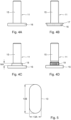
- FIGs 4A-4D some embodiments of low head bolts 11 which can be used in a semitrailer towing vehicle comprising a fifth wheel assembly according to the invention are schematically shown.
- the low heads bolts 11 have a shank 15 having a uniform diameter.
- the difference between the embodiment shown in Figure 4A (also shown in Figure 3A ) and the embodiment shown in Figure 4B is that in the embodiment shown in Figure 4B (also shown in Figure 3B ) the head 16 of the bolt 15 comprises a flange 17 having an extended diameter, i.e. having a diameter larger than a diameter of the head 16.
- the bolt 11 has a circular neck 18 adjacent the head 16.
- the diameter of the circular neck 18 is such that the circular neck 18 of the bolt 11 tightly fits in the larger second hole 14 provided in the corrugated mounting plate 5.
- the height NH of the circular neck 18 is smaller than a thickness of the corrugated mounting plate 5, so that the circular neck 18 can only engage the inside of the second hole 14 of the corrugated mounting plate 5.
- the circular neck 18 can have a smooth surface as indicated in Figure 4C .
- the neck 19 is ribbed as shown in the embodiment of Figure 4D , the ribbed neck 19 engaging an inside of a second hole 14 in the corrugated mounting plate 5. Such a bolt 11 with a ribbed neck 19 can be pressed into the second hole 14 of the corrugated mounting plate during assembly of the fifth wheel assembly.
- the bolts 11, 12 used in the shown embodiments of the semitrailer towing vehicle according to the invention are preferably 10.9 grade, M16 bolts.
- the inventive low head bolts 11, 12 of this material are sufficiently strong to withstand the shear forces generated during operation of the semitrailer towing vehicle.
Landscapes
- Engineering & Computer Science (AREA)
- Chemical & Material Sciences (AREA)
- Combustion & Propulsion (AREA)
- Transportation (AREA)
- Mechanical Engineering (AREA)
- Vehicle Cleaning, Maintenance, Repair, Refitting, And Outriggers (AREA)
- Handcart (AREA)
Claims (14)
- Sattelzugfahrzeug mit einer Sattelkupplungsbaugruppe (1), die Lagerböcke (2, 3) und eine Sattelkupplungsplatte (4), die um eine quer zur Fahrtrichtung verlaufende Achse schwenkbar an den Lagerböcken (2, 3) montiert ist, aufweist, wobei die Lagerböcke (2, 3) an einer gewellten Montageplatte (5) befestigt sind, wobei die gewellte Montageplatte (5) an einem Fahrgestell (8) des Sattelzugfahrzeugs angebracht ist, wobei die gewellte Montageplatte (5) obere Abschnitte (9) und untere Abschnitte (10) aufweist, wobei der Abstand (H) zwischen dem oberen und unteren Abschnitt (9, 10) eine Höhe der gewellten Montageplatte (5) definiert, wobei die oberen Abschnitte (9) näher an der Sattelkupplungsplatte (4) positioniert sind als die unteren Abschnitte (10), wobei die Lagerblöcke (2, 3) an der gewellten Montageplatte (5) durch Bolzen (11, 12) befestigt sind, die durch erste Löcher (13), die in den Lagerblöcken (2, 3) bereitgestellt sind, und zweite Löcher (14), die in der gewellten Montageplatte (5) bereitgestellt sind, hindurchgehen, dadurch gekennzeichnet, dass die Bolzen (11, 12) eine Kopfhöhe vom 0,25-bis 0,4-fachen des Schaftdurchmessers der Bolzen (11, 12) aufweisen, dass die Kopfhöhe der Bolzen (11, 12) kleiner als die Höhe der gewellten Montageplatte (5) ist und dass die Köpfe (16) der Bolzen (11, 12) in eine untere Fläche (L) eines oberen Abschnitts (9) der gewellten Montageplatte (5) eingreifen, wobei die untere Fläche (L) gegenüber der Sattelkupplungsplatte (4) positioniert ist.
- Sattelzugfahrzeug nach Anspruch 1, dadurch gekennzeichnet, dass die in den Lagerböcken (2, 3) bereitgestellten ersten Löcher (13) Langlöcher sind, die jeweils einen ersten kurzen Durchmesser (13A) in Querrichtung und einen ersten langen Durchmesser (13B) in Längsrichtung aufweisen, wobei der erste lange Durchmesser (13B) größer ist als der erste kurze Durchmesser (13A), und dass die zweiten Löcher (14) in der gewellten Montageplatte (5) kreisförmig sind und einen einheitlichen zweiten Durchmesser aufweisen.
- Sattelzugfahrzeug nach Anspruch 2, dadurch gekennzeichnet, dass der erste kurze Durchmesser (13A) der ersten Löcher (13) in den Lagerböcken (2, 3) gleich dem zweiten Durchmesser der zweiten Löcher (14) in der gewellten Montageplatte (5) ist.
- Sattelzugfahrzeug nach einem der vorhergehenden Ansprüche, dadurch gekennzeichnet, dass die Bolzen (11, 12) einen einheitlichen Schaftdurchmesser aufweisen.
- Sattelzugfahrzeug nach Anspruch 4, dadurch gekennzeichnet, dass der Kopf (16) des Bolzens (11, 12) einen Flansch (17) umfasst, dessen Durchmesser größer als der Durchmesser des Kopfes (16) ist.
- Sattelzugfahrzeug nach Anspruch 1, 2 oder 3, dadurch gekennzeichnet, dass die Bolzen (11, 12) einen gerippten Hals (19) aufweisen, wobei der gerippte Hals (19) wenigstens in eine Innenseite eines zweiten Lochs (14) in der gewellten Montageplatte (5) eingreift.
- Sattelzugfahrzeug nach Anspruch 2, dadurch gekennzeichnet, dass der erste kurze Durchmesser (13A) der ersten Löcher (13) in den Lagerböcken (2, 3) kleiner ist als der zweite Durchmesser der zweiten Löcher (14) in der gewellten Montageplatte (5), dass die Bolzen (11, 12) einen kreisförmigen Hals (18) neben dem Kopf (16) aufweisen, dass die Bolzen (11, 12) einen kreisförmigen Hals (18) in der Nähe des Kopfes (16) aufweisen, wobei der kreisförmige Hals (18) einen solchen Halsdurchmesser aufweist, dass der kreisförmige Hals (18) der Bolzen (11, 12) in den zweiten Löchern (14) anliegt, die in der gewellten Montageplatte (5) bereitgestellt sind, und dass die Höhe des kreisförmigen Halses (18) kleiner als eine Dicke der gewellten Montageplatte (5) ist.
- Sattelzugfahrzeug nach einem der Ansprüche 4, 5 oder 6 in Abhängigkeit von Anspruch 2 oder nach Anspruch 7, dadurch gekennzeichnet, dass der Schaft (15) der Bolzen (11, 12) einen solchen Durchmesser aufweist, dass der Schaft (15) der Bolzen (11, 12) in Querrichtung der in den Lagerböcken (2, 3) der Sattelkupplungsbaugruppe (1) bereitgestellten Langlöcher (13) dicht anliegt.
- Sattelzugfahrzeug nach wenigstens Anspruch 2, dadurch gekennzeichnet, dass der erste kurze Durchmesser (13A) 18 mm beträgt.
- Sattelzugfahrzeug nach Anspruch 7, dadurch gekennzeichnet, dass der zweite Durchmesser der zweiten Löcher (14) 23 mm und der Halsdurchmesser der Bolzen (11, 12) 21 mm beträgt.
- Sattelzugfahrzeug nach einem der vorhergehenden Ansprüche, dadurch gekennzeichnet, dass die Bolzen (11, 12) M16-Bolzen sind.
- Sattelzugfahrzeug nach einem der vorhergehenden Ansprüche, dadurch gekennzeichnet, dass die Bolzen (11, 12) Bolzen der Güte 10,9 sind.
- Sattelzugfahrzeug nach einem der vorhergehenden Ansprüche, dadurch gekennzeichnet, dass die gewellte Montageplatte (5) aus S600MC besteht und eine Dicke zwischen 3 und 9 mm aufweist, wobei die gewellte Montageplatte (5) eine Dicke von 6 mm vorzugsweise aufweist.
- Sattelzugfahrzeug nach Anspruch 13, dadurch gekennzeichnet, dass die gewellte Montageplatte (5) ein Gewicht von 30 kg oder weniger aufweist.
Applications Claiming Priority (2)
| Application Number | Priority Date | Filing Date | Title |
|---|---|---|---|
| NL2023076A NL2023076B1 (en) | 2019-05-06 | 2019-05-06 | A semitrailer towing vehicle comprising a fifth wheel assembly. |
| PCT/NL2020/050288 WO2020226494A1 (en) | 2019-05-06 | 2020-05-06 | A semitrailer towing vehicle comprising a fifth wheel assembly. |
Publications (3)
| Publication Number | Publication Date |
|---|---|
| EP3966090A1 EP3966090A1 (de) | 2022-03-16 |
| EP3966090C0 EP3966090C0 (de) | 2023-06-07 |
| EP3966090B1 true EP3966090B1 (de) | 2023-06-07 |
Family
ID=66690923
Family Applications (1)
| Application Number | Title | Priority Date | Filing Date |
|---|---|---|---|
| EP20725964.9A Active EP3966090B1 (de) | 2019-05-06 | 2020-05-06 | Sattelschlepperfahrzeug mit einer sattelkupplung |
Country Status (3)
| Country | Link |
|---|---|
| EP (1) | EP3966090B1 (de) |
| NL (1) | NL2023076B1 (de) |
| WO (1) | WO2020226494A1 (de) |
Families Citing this family (2)
| Publication number | Priority date | Publication date | Assignee | Title |
|---|---|---|---|---|
| CN112406683B (zh) * | 2020-12-18 | 2024-04-02 | 河北富华专用汽车制造有限公司 | 一种用于半挂车运输的钢卷固定装置 |
| CN114987635A (zh) * | 2022-05-31 | 2022-09-02 | 东风柳州汽车有限公司 | 一种车用牵引座底板及其生产工艺 |
Family Cites Families (3)
| Publication number | Priority date | Publication date | Assignee | Title |
|---|---|---|---|---|
| DE3033364C2 (de) * | 1980-09-04 | 1983-03-03 | Rockinger Spezialfabrik für Anhängerkupplungen GmbH & Co, 8000 München | Anordnung einer Sattelkupplung auf einer Brückenkonstruktion eines Sattelschleppers |
| DE4135288A1 (de) | 1991-10-25 | 1993-04-29 | Rockinger Spezial Fab Joh | Sattelzugfahrzeug |
| DE102016208457A1 (de) * | 2016-05-18 | 2017-11-23 | Bayerische Motoren Werke Aktiengesellschaft | Verfahren zum Ausbilden einer Bauteilanordnung und Bauteilanordnung |
-
2019
- 2019-05-06 NL NL2023076A patent/NL2023076B1/en not_active IP Right Cessation
-
2020
- 2020-05-06 EP EP20725964.9A patent/EP3966090B1/de active Active
- 2020-05-06 WO PCT/NL2020/050288 patent/WO2020226494A1/en not_active Ceased
Also Published As
| Publication number | Publication date |
|---|---|
| WO2020226494A1 (en) | 2020-11-12 |
| EP3966090C0 (de) | 2023-06-07 |
| NL2023076B1 (en) | 2020-11-30 |
| EP3966090A1 (de) | 2022-03-16 |
Similar Documents
| Publication | Publication Date | Title |
|---|---|---|
| EP3966090B1 (de) | Sattelschlepperfahrzeug mit einer sattelkupplung | |
| US20070194564A1 (en) | Trailer and method of assembly | |
| US8414046B2 (en) | Reinforced vehicle structure | |
| US8408638B2 (en) | Reinforced vehicle structure | |
| EP3577349B1 (de) | Befestigungselement | |
| US11421748B2 (en) | Coil spring support for vehicular suspension system | |
| CN110770454A (zh) | 用于紧固内衬元件的方法和紧固装置 | |
| US8449022B2 (en) | Reinforced vehicle structure | |
| US2402254A (en) | Fifth wheel mounting | |
| CN207345466U (zh) | 一种电池包下壳体加强结构 | |
| CN212290036U (zh) | 一种半挂车车架加强结构 | |
| CN114211917A (zh) | 汽车拖曳装置 | |
| US12485968B2 (en) | Wheel deflector | |
| KR101983793B1 (ko) | 화물차의 적재함 고정용 클램핑 장치 | |
| US6820882B2 (en) | Vehicle rear body structure | |
| CN211076099U (zh) | 一种轻量化铝合金双扭杆翻转支座 | |
| CN104176130A (zh) | 车辆的转向支撑构件的支撑结构 | |
| CN208165102U (zh) | 一种混凝土搅拌运输车大梁和副梁的紧固装置 | |
| JP2008049878A (ja) | アクスルの取付構造 | |
| CN113954593A (zh) | 一种钢板弹簧总成紧固结构 | |
| CN219728315U (zh) | 副车架安装结构及车辆 | |
| CN222522755U (zh) | 备胎安装结构总成及车辆 | |
| CN216046847U (zh) | 一种液化气体罐车防冲装置 | |
| CN223407896U (zh) | 后防护装置及车辆 | |
| CN107415887B (zh) | 一种安全带安装组件 |
Legal Events
| Date | Code | Title | Description |
|---|---|---|---|
| STAA | Information on the status of an ep patent application or granted ep patent |
Free format text: STATUS: UNKNOWN |
|
| STAA | Information on the status of an ep patent application or granted ep patent |
Free format text: STATUS: THE INTERNATIONAL PUBLICATION HAS BEEN MADE |
|
| PUAI | Public reference made under article 153(3) epc to a published international application that has entered the european phase |
Free format text: ORIGINAL CODE: 0009012 |
|
| STAA | Information on the status of an ep patent application or granted ep patent |
Free format text: STATUS: REQUEST FOR EXAMINATION WAS MADE |
|
| 17P | Request for examination filed |
Effective date: 20211110 |
|
| AK | Designated contracting states |
Kind code of ref document: A1 Designated state(s): AL AT BE BG CH CY CZ DE DK EE ES FI FR GB GR HR HU IE IS IT LI LT LU LV MC MK MT NL NO PL PT RO RS SE SI SK SM TR |
|
| DAV | Request for validation of the european patent (deleted) | ||
| DAX | Request for extension of the european patent (deleted) | ||
| GRAP | Despatch of communication of intention to grant a patent |
Free format text: ORIGINAL CODE: EPIDOSNIGR1 |
|
| STAA | Information on the status of an ep patent application or granted ep patent |
Free format text: STATUS: GRANT OF PATENT IS INTENDED |
|
| INTG | Intention to grant announced |
Effective date: 20221223 |
|
| GRAS | Grant fee paid |
Free format text: ORIGINAL CODE: EPIDOSNIGR3 |
|
| GRAA | (expected) grant |
Free format text: ORIGINAL CODE: 0009210 |
|
| STAA | Information on the status of an ep patent application or granted ep patent |
Free format text: STATUS: THE PATENT HAS BEEN GRANTED |
|
| AK | Designated contracting states |
Kind code of ref document: B1 Designated state(s): AL AT BE BG CH CY CZ DE DK EE ES FI FR GB GR HR HU IE IS IT LI LT LU LV MC MK MT NL NO PL PT RO RS SE SI SK SM TR |
|
| REG | Reference to a national code |
Ref country code: GB Ref legal event code: FG4D |
|
| P01 | Opt-out of the competence of the unified patent court (upc) registered |
Effective date: 20230505 |
|
| REG | Reference to a national code |
Ref country code: CH Ref legal event code: EP Ref country code: AT Ref legal event code: REF Ref document number: 1574196 Country of ref document: AT Kind code of ref document: T Effective date: 20230615 |
|
| REG | Reference to a national code |
Ref country code: DE Ref legal event code: R096 Ref document number: 602020012110 Country of ref document: DE |
|
| U01 | Request for unitary effect filed |
Effective date: 20230706 |
|
| U07 | Unitary effect registered |
Designated state(s): AT BE BG DE DK EE FI FR IT LT LU LV MT NL PT SE SI Effective date: 20230718 |
|
| P04 | Withdrawal of opt-out of the competence of the unified patent court (upc) registered |
Effective date: 20230714 |
|
| REG | Reference to a national code |
Ref country code: LT Ref legal event code: MG9D |
|
| PG25 | Lapsed in a contracting state [announced via postgrant information from national office to epo] |
Ref country code: NO Free format text: LAPSE BECAUSE OF FAILURE TO SUBMIT A TRANSLATION OF THE DESCRIPTION OR TO PAY THE FEE WITHIN THE PRESCRIBED TIME-LIMIT Effective date: 20230907 Ref country code: ES Free format text: LAPSE BECAUSE OF FAILURE TO SUBMIT A TRANSLATION OF THE DESCRIPTION OR TO PAY THE FEE WITHIN THE PRESCRIBED TIME-LIMIT Effective date: 20230607 |
|
| PG25 | Lapsed in a contracting state [announced via postgrant information from national office to epo] |
Ref country code: RS Free format text: LAPSE BECAUSE OF FAILURE TO SUBMIT A TRANSLATION OF THE DESCRIPTION OR TO PAY THE FEE WITHIN THE PRESCRIBED TIME-LIMIT Effective date: 20230607 Ref country code: HR Free format text: LAPSE BECAUSE OF FAILURE TO SUBMIT A TRANSLATION OF THE DESCRIPTION OR TO PAY THE FEE WITHIN THE PRESCRIBED TIME-LIMIT Effective date: 20230607 Ref country code: GR Free format text: LAPSE BECAUSE OF FAILURE TO SUBMIT A TRANSLATION OF THE DESCRIPTION OR TO PAY THE FEE WITHIN THE PRESCRIBED TIME-LIMIT Effective date: 20230908 |
|
| PG25 | Lapsed in a contracting state [announced via postgrant information from national office to epo] |
Ref country code: SK Free format text: LAPSE BECAUSE OF FAILURE TO SUBMIT A TRANSLATION OF THE DESCRIPTION OR TO PAY THE FEE WITHIN THE PRESCRIBED TIME-LIMIT Effective date: 20230607 |
|
| PG25 | Lapsed in a contracting state [announced via postgrant information from national office to epo] |
Ref country code: IS Free format text: LAPSE BECAUSE OF FAILURE TO SUBMIT A TRANSLATION OF THE DESCRIPTION OR TO PAY THE FEE WITHIN THE PRESCRIBED TIME-LIMIT Effective date: 20231007 |
|
| PG25 | Lapsed in a contracting state [announced via postgrant information from national office to epo] |
Ref country code: SM Free format text: LAPSE BECAUSE OF FAILURE TO SUBMIT A TRANSLATION OF THE DESCRIPTION OR TO PAY THE FEE WITHIN THE PRESCRIBED TIME-LIMIT Effective date: 20230607 Ref country code: SK Free format text: LAPSE BECAUSE OF FAILURE TO SUBMIT A TRANSLATION OF THE DESCRIPTION OR TO PAY THE FEE WITHIN THE PRESCRIBED TIME-LIMIT Effective date: 20230607 Ref country code: RO Free format text: LAPSE BECAUSE OF FAILURE TO SUBMIT A TRANSLATION OF THE DESCRIPTION OR TO PAY THE FEE WITHIN THE PRESCRIBED TIME-LIMIT Effective date: 20230607 Ref country code: IS Free format text: LAPSE BECAUSE OF FAILURE TO SUBMIT A TRANSLATION OF THE DESCRIPTION OR TO PAY THE FEE WITHIN THE PRESCRIBED TIME-LIMIT Effective date: 20231007 Ref country code: CZ Free format text: LAPSE BECAUSE OF FAILURE TO SUBMIT A TRANSLATION OF THE DESCRIPTION OR TO PAY THE FEE WITHIN THE PRESCRIBED TIME-LIMIT Effective date: 20230607 |
|
| PG25 | Lapsed in a contracting state [announced via postgrant information from national office to epo] |
Ref country code: PL Free format text: LAPSE BECAUSE OF FAILURE TO SUBMIT A TRANSLATION OF THE DESCRIPTION OR TO PAY THE FEE WITHIN THE PRESCRIBED TIME-LIMIT Effective date: 20230607 |
|
| REG | Reference to a national code |
Ref country code: DE Ref legal event code: R097 Ref document number: 602020012110 Country of ref document: DE |
|
| PLBE | No opposition filed within time limit |
Free format text: ORIGINAL CODE: 0009261 |
|
| STAA | Information on the status of an ep patent application or granted ep patent |
Free format text: STATUS: NO OPPOSITION FILED WITHIN TIME LIMIT |
|
| 26N | No opposition filed |
Effective date: 20240308 |
|
| U20 | Renewal fee for the european patent with unitary effect paid |
Year of fee payment: 5 Effective date: 20240418 |
|
| REG | Reference to a national code |
Ref country code: CH Ref legal event code: PL |
|
| P05 | Withdrawal of opt-out of the competence of the unified patent court (upc) changed |
Free format text: CASE NUMBER: APP_550276/2023 Effective date: 20230718 |
|
| PG25 | Lapsed in a contracting state [announced via postgrant information from national office to epo] |
Ref country code: MC Free format text: LAPSE BECAUSE OF FAILURE TO SUBMIT A TRANSLATION OF THE DESCRIPTION OR TO PAY THE FEE WITHIN THE PRESCRIBED TIME-LIMIT Effective date: 20230607 |
|
| PG25 | Lapsed in a contracting state [announced via postgrant information from national office to epo] |
Ref country code: MC Free format text: LAPSE BECAUSE OF FAILURE TO SUBMIT A TRANSLATION OF THE DESCRIPTION OR TO PAY THE FEE WITHIN THE PRESCRIBED TIME-LIMIT Effective date: 20230607 Ref country code: CH Free format text: LAPSE BECAUSE OF NON-PAYMENT OF DUE FEES Effective date: 20240531 |
|
| PG25 | Lapsed in a contracting state [announced via postgrant information from national office to epo] |
Ref country code: IE Free format text: LAPSE BECAUSE OF NON-PAYMENT OF DUE FEES Effective date: 20240506 |
|
| U20 | Renewal fee for the european patent with unitary effect paid |
Year of fee payment: 6 Effective date: 20250401 |
|
| PG25 | Lapsed in a contracting state [announced via postgrant information from national office to epo] |
Ref country code: CY Free format text: LAPSE BECAUSE OF FAILURE TO SUBMIT A TRANSLATION OF THE DESCRIPTION OR TO PAY THE FEE WITHIN THE PRESCRIBED TIME-LIMIT; INVALID AB INITIO Effective date: 20200506 |
|
| PG25 | Lapsed in a contracting state [announced via postgrant information from national office to epo] |
Ref country code: HU Free format text: LAPSE BECAUSE OF FAILURE TO SUBMIT A TRANSLATION OF THE DESCRIPTION OR TO PAY THE FEE WITHIN THE PRESCRIBED TIME-LIMIT; INVALID AB INITIO Effective date: 20200506 |
|
| PGFP | Annual fee paid to national office [announced via postgrant information from national office to epo] |
Ref country code: GB Payment date: 20260324 Year of fee payment: 7 |