EP3965702B1 - Zwangsmechanismen zur selektiven entfaltung einer medizinischen vorrichtung - Google Patents
Zwangsmechanismen zur selektiven entfaltung einer medizinischen vorrichtung Download PDFInfo
- Publication number
- EP3965702B1 EP3965702B1 EP19726265.2A EP19726265A EP3965702B1 EP 3965702 B1 EP3965702 B1 EP 3965702B1 EP 19726265 A EP19726265 A EP 19726265A EP 3965702 B1 EP3965702 B1 EP 3965702B1
- Authority
- EP
- European Patent Office
- Prior art keywords
- constraining fiber
- constraining
- row
- constraint
- fiber
- Prior art date
- Legal status (The legal status is an assumption and is not a legal conclusion. Google has not performed a legal analysis and makes no representation as to the accuracy of the status listed.)
- Active
Links
Images


Classifications
-
- A—HUMAN NECESSITIES
- A61—MEDICAL OR VETERINARY SCIENCE; HYGIENE
- A61F—FILTERS IMPLANTABLE INTO BLOOD VESSELS; PROSTHESES; DEVICES PROVIDING PATENCY TO, OR PREVENTING COLLAPSING OF, TUBULAR STRUCTURES OF THE BODY, e.g. STENTS; ORTHOPAEDIC, NURSING OR CONTRACEPTIVE DEVICES; FOMENTATION; TREATMENT OR PROTECTION OF EYES OR EARS; BANDAGES, DRESSINGS OR ABSORBENT PADS; FIRST-AID KITS
- A61F2/00—Filters implantable into blood vessels; Prostheses, i.e. artificial substitutes or replacements for parts of the body; Appliances for connecting them with the body; Devices providing patency to, or preventing collapsing of, tubular structures of the body, e.g. stents
- A61F2/95—Instruments specially adapted for placement or removal of stents or stent-grafts
- A61F2/962—Instruments specially adapted for placement or removal of stents or stent-grafts having an outer sleeve
- A61F2/97—Instruments specially adapted for placement or removal of stents or stent-grafts having an outer sleeve the outer sleeve being splittable
-
- D—TEXTILES; PAPER
- D04—BRAIDING; LACE-MAKING; KNITTING; TRIMMINGS; NON-WOVEN FABRICS
- D04B—KNITTING
- D04B19/00—Unravelling knitted fabrics
-
- D—TEXTILES; PAPER
- D04—BRAIDING; LACE-MAKING; KNITTING; TRIMMINGS; NON-WOVEN FABRICS
- D04B—KNITTING
- D04B21/00—Warp knitting processes for the production of fabrics or articles not dependent on the use of particular machines; Fabrics or articles defined by such processes
- D04B21/20—Warp knitting processes for the production of fabrics or articles not dependent on the use of particular machines; Fabrics or articles defined by such processes specially adapted for knitting articles of particular configuration
- D04B21/202—Warp knitting processes for the production of fabrics or articles not dependent on the use of particular machines; Fabrics or articles defined by such processes specially adapted for knitting articles of particular configuration warp knitted yarns
-
- D—TEXTILES; PAPER
- D04—BRAIDING; LACE-MAKING; KNITTING; TRIMMINGS; NON-WOVEN FABRICS
- D04B—KNITTING
- D04B21/00—Warp knitting processes for the production of fabrics or articles not dependent on the use of particular machines; Fabrics or articles defined by such processes
- D04B21/20—Warp knitting processes for the production of fabrics or articles not dependent on the use of particular machines; Fabrics or articles defined by such processes specially adapted for knitting articles of particular configuration
- D04B21/205—Elongated tubular articles of small diameter, e.g. coverings or reinforcements for cables or hoses
-
- D—TEXTILES; PAPER
- D10—INDEXING SCHEME ASSOCIATED WITH SUBLASSES OF SECTION D, RELATING TO TEXTILES
- D10B—INDEXING SCHEME ASSOCIATED WITH SUBLASSES OF SECTION D, RELATING TO TEXTILES
- D10B2509/00—Medical; Hygiene
- D10B2509/06—Vascular grafts; stents
Definitions
- the present disclosure relates to apparatuses, systems, and methods that include constraints used in delivery of implantable medical devices. More specifically, the present disclosure relates to apparatuses, systems, and methods that include constraints for selective deployment of an expandable device during device delivery.
- Stents and stent-grafts may be utilized to radially support a variety of tubular passages in the body, including arteries, veins, airways, gastrointestinal tracts, and biliary tracts.
- the preferred method of placing these devices has been to use specialized delivery systems to precisely place and deploy a device at the site to be treated. These delivery systems allow the practitioner to minimize the trauma and technical difficulties associated with device placements. Attributes of delivery systems include: low profile; ability to pass through introducer sheaths; ability to negotiate tortuous vasculature, smoothly and atraumatically; protection of constrained devices; and ability to accurately position and deploy the device.
- Stents or stent-grafts may be deployed and plastically deformed, such as by using an inflatable balloon, or to self-expand, such as through elastic recovery, from a collapsed or constrained delivery diameter to an expanded and deployed diameter.
- Some stents are designed to elastically recover by being manufactured at their functional diameter out of a material that has elastic recovery properties, and then radially compressed to be mounted on a delivery catheter.
- stent and stent-graft devices may be held, compressed, or constrained in the delivery configuration prior to and during delivery to a target location.
- US patent specification No. US 6224627 discloses a thin tubular multiple filament (film or fiber) structure that can hold high internal pressures. When desired, an extension of the filaments can be pulled in any direction to unfurl the structure.
- This device is disclosed for use in self expanding stent or stent graft delivery systems, balloon dilatation catheters, removable guide wire lumens for catheters, drug infusion or suction catheters, guide wire bundling casings, removable filters, removable wire insulation, removable packaging and other applications.
- a medical device deployment apparatus includes at least one first constraining fiber arranged as a series of multiple loops to form a warp knit surrounding the medical device in a constrained configuration, the warp knit being configured to separate and be removed to deploy the medical device; and at least one second constraining fiber arranged with the at least one first constraining fiber, the at least one second constraining fiber having at least one loop arranged in a non-warp knit pattern.
- the terms “about” and “approximately” may be used, interchangeably, to refer to a measurement that includes the stated measurement and that also includes any measurements that are reasonably close to the stated measurement. Measurements that are reasonably close to the stated measurement deviate from the stated measurement by a reasonably small amount as understood and readily ascertained by individuals having ordinary skill in the relevant arts. Such deviations may be attributable to measurement error or minor adjustments made to optimize performance, for example. In the event it is determined that individuals having ordinary skill in the relevant arts would not readily ascertain values for such reasonably small differences, the terms “about” and “approximately” can be understood to mean plus or minus 10% of the stated value.
- constraints may include one or more fibers that are arranged together.
- the fibers may be interwoven, stitched, or otherwise interlocked together circumferentially about the device.
- one or more of the fibers may be unknitted or disrupted from the other fibers in the constraint.
- Constrained devices may store energy as a result of being constrained in a diameter smaller than a natural or deployed diameter. Thus, the devices may exhibit a radial displacement force against the zipper. During deployment of constrained devices, the radial force may force unknitting of the constraint without user involvement such that the constraint self un-knitts. The aspects of the present disclosure, however, eliminate this accelerated deployment. As discussed in further detail below, the constraint may include a pattern or knot structure that lessens accelerated deployment.
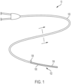
- FIG. 1 is a top plan view of a catheter 100 with a constraint 102, according to some embodiments.
- the constraint 102 is configured to constraint an implantable medical device 104 to a delivery configuration.
- the constraint 102 may include one or more fibers 106 arranged about the implantable medical device 104 to maintain the constraint 102 in a constrained configuration.
- the constraint 102 is arranged along a length of the implantable medical device 104.
- the constraint 102 is also circumferentially arranged about the implantable medical device 104 and may substantially cover the implantable medical device 104 for delivery.
- the one or more fibers 106 may be arranged within a lumen (not shown) of the catheter 100 and extend toward a proximal end of the catheter 100 that is arranged external to a patient during delivery of the implantable medical device 104.
- the one or more fibers 106 include a proximal end 108 that a user may apply tension to in order to release the constraint 102 and deploy the implantable medical device 104.
- the one or more fibers 106 release similar to a rip cord such that interlocking portions (e.g., overlapping fibers or knots) sequentially release along the length of the implantable medical device 104.
- the constraint 102 is formed by interlocking together the one or more fibers 106 directly on the implantable medical device 104.
- the constraint 102 is formed directly on the implantable medical device 104.
- the expandable medical device 104 may be a stent, stent-graft, a balloon, or a similar device.
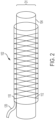
- FIG. 2 is a side view of the device 104 including the constraint 102, in accordance with an embodiment.
- the device 104 includes a delivery diameter D1 and a deployed diameter D2 (not shown) that is larger than the delivery diameter D1.
- the removable constraint 102 is attached to the device 104 at its delivery diameter D1.
- the constraint 102 includes at least one constraining fiber in the form of a warp knit.
- the constraint 102 may include a first constraining fiber 110 and a second constraining fiber 112.
- the first and/or the second constraining fiber(s) 110, 112 may operate, for example, as a deployment line 120 configured to release the constraint 102 and transition the device 104 from the delivery diameter D1 to the deployed diameter D2 in response to a force applied to the deployment line 120 (which may be coupled to one or more of the knot rows 114 as discussed in further detail below).
- the device 104 may have a desired deployed diameter D2 from about 5mm-15mm, or 6mm-9mm, or 6mm-12mm, 10mm-20mm, 15mm-30mm, 25mm-45mm, for example, and a delivery diameter D1 that is less than the deployed diameter D2.
- a ratio of the delivery diameter D1 of the device 104 to the deployed diameter D2 (not shown) of the device 104 is less than about 0.3, less than about 0.29, less than about 0.28, less than about 0.27, or less than about 0.26.
- the term "diameter” is not meant to require a circular cross-section, and is instead to be understood broadly to reference a maximum transverse cross-sectional dimension of a device 104.
- FIG. 3 is an illustration of a first constraining fiber 110 and a second constraining fiber 112, in accordance with an embodiment.
- the first constraining fiber 110 and the second constraining fiber 112 each include a series of loops 220, 222, respectively. A single one of the series of loops 220, 222 is shown highlighted in FIG. 3 for ease of illustration.
- the first constraining fiber 110 and the second constraining fiber 112 may form a medical device deployment apparatus in certain instances.
- the first constraining fiber 110 and the second constraining fiber 112 are formed of a single constraining fiber that is looped upon itself to form two lines 110, 112.
- the loops 220 of the first constraining fiber 110 may form a warp knit that surrounds a medical device in a constrained configuration as shown in FIG. 3 .
- the first constraining fiber 110 forming a warp knit may be one of a group of fibers that form a warp knit in one or more rows of a constraint 102.
- the loops 222 of the second constraining fiber 112 may be arranged with the first constraining fiber 110 with the second constraining fiber 112 having at least one loop 224 arranged in a non-warp knit pattern. As shown in FIG. 3 , the at least one loop 224 is a distal most loop of the multiple loops 222.
- each of the loops 22 of the second constraining fiber 112 may include the non-warp knit pattern.
- the first constraining fiber 110 and the second constraining fiber 112 may form a constraint 102.
- the loop 224 having the non-warp knit pattern is arranged at a distal end of the constraint 102.
- the loop 224 may be arranged in a chain-link stich.
- the at least one loop 224 arranged in a non-warp knit pattern is arranged with the non-warp knit pattern and interrupts the warp knit
- the first constraining fiber 110 may be interwoven with the second constraining fiber 112 to form the constraint 102 with each of the first constraining fiber 100 and the second constraining fiber 122 forming a row of knots. As shown in FIG. 3 , the first constraining fiber 110 and the second constraining fiber 112 are interwoven to form a single knot row 226. As discussed and shown in FIGS. 4A-B , the constraint 102 may include additional knot rows 226.
- the constraint 102 may be deployed by interrupting the knot row 226 by applying tension to a deployment line.
- the first constraining fiber 110 and the second constraining fiber 112 may be combined to form a deployment line.
- the knot row 226 may be one of a number of rows formed in the constraint 102.
- the first constraining fiber 110 may include multiple fibers knitted together.
- the first constraining fiber 110 may be a group or type of fiber that forms a pattern.
- the second constraining fiber 112 may be a group or type of fiber that forms a pattern.
- the first constraining fiber 110 (group) may form a first row of the row of knots in a warp knit pattern and a second row of the row of knots is formed by the second constraining fiber 112 (group) in a non-warp knit pattern.
- the non-warp knit pattern of the second row comprises chain-link stiches.
- the at least one first constraining fiber 110 includes the first constraining fiber 110 and a third constraining fiber and the at least one second constraining fiber 112 includes the second constraining fiber 112 and a fourth constraining fiber with the first constraining fiber, second constraining fiber, the third constraining fiber, and the fourth constraining fiber being interwoven to form a constraint 102 as discussed with reference to FIGS. 4A-D .
- the non-warp knit pattern, knot or stitch, used in a constraint 102 that includes one or more additional knot rows with these rows formed in a knit or warp knit lessens the opportunity for self-deployment of the constraint 102.
- a chain stitch, formed by the one loop 224 in a row 226 or all loops in a row of a constraint 102, that includes one or more additional knot rows with these rows formed in a knit or warp knit facilitates controlled deployment of the constraint 102.
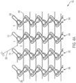
- FIG. 4A is an illustration of a constraint 102 in a first arrangement, in accordance with an embodiment.
- the constraint 102 is shown as a sheet of interwoven fibers, however, the constraint 102 may be arranged circumferentially about an implantable medical device.
- the constraint 102 can include a first constraining fiber 110 and a second constraining fiber 112 as described above with reference to FIG. 3 that form multiple knot rows.
- the constraint 102 includes a first constraining fiber 110, a second constraining fiber 112, a third constraining fiber 338, and a fourth constraining fiber 340.
- the constraining fibers 110, 112, 338, 340 may be arranged together to form multiple knot rows 342, 344, 346, 348.
- the number of constraining fibers 110, 112, 338, 340 may be equal to the number of knot rows 342, 344, 346, 348.
- the constraining fibers 110, 112, 338, 340 may be interwoven or interlocked with one another to form the knot rows 342, 344, 346, 348.
- the first row of knots 342 of the constraint 102 may be formed by the first constraining fiber 110 interwoven with the second constraining fiber 112. As shown, the first constraining fiber 110 are interwoven with the second constraining fiber 112 to form the knot row 342 in a warp knit.
- the knot row 342 may be a warp knit when the constraint 102 is surrounding the medical device in the constrained configuration.
- the second row of knots 344 may be formed by the second constraining fiber 112 interwoven with the third constraining fiber 338.
- the second constraining fiber 112 may be interwoven with the third constraining fiber 338 to form a non-warp knit with the row of knots 344.
- the knot row 344 may be a warp knit when the constraint 102 is surrounding the medical device in the constrained configuration.
- the constraint 102 includes the multiple knot rows 342, 344, 346, 348 with the first row of knots 342 being formed by the first constraining fiber 110 interwoven with the second constraining fiber 112, the second row of knots 344 formed by the second constraining fiber 112 interwoven with the third constraining fiber 388, the third row of knots 346 formed by the third constraining fiber 348 interwoven with the fourth constraining fiber 340, and the fourth row of knots 348 formed by the fourth constraining fiber 340 interwoven with the first constraining fiber 110.
- one or more of the rows 342, 344, 346, 348 forms a knit or a warp knit pattern with loops of the constraining fibers 110, 112, 338, 340 and another of the one or more of the rows 342, 344, 346, 348 forms a non-knit or non-warp knit pattern with one or more of the loops (e.g., a distal loop as described with reference to FIG. 3 ) of the constraining fibers 110, 112, 338, 340.
- At least one of the third row 346 and the fourth row 348 forms a warp knit surrounding the medical device in the constrained configuration and another of the third row 346 and the fourth row 348 forms a non-warp knit surrounding the medical device in the constrained configuration.
- the constraint 102 may include three of the rows 342, 344, 346, 348 in the warp pattern and one of the rows 342, 344, 346, 348 in a non-warp pattern.
- the one or more rows 342, 344, 346, 348 being in the non-warp pattern includes a single knot being arranged in a non-warp stitch (e.g., a chain stitch), two or more of the knots of the one or more rows 342, 344, 346, 348 being a non-warp stitch, multiple knots of the one or more rows 342, 344, 346, 348 being a non-warp stitch, alternating knots of the one or more rows 342, 344, 346, 348 being a non-warp stitch, two or more or all of the knots of the one or more rows 342, 344, 346, 348 being in a non-warp stitch.
- a non-warp stitch e.g., a chain stitch
- the non-warp pattern of one or more of the rows 342, 344, 346, 348 may lessen the opportunity for accelerated or unwanted deployment of the constraint 102.
- the different non-warp pattern of one or more of the rows 342, 344, 346, 348 interrupts the pattern of the constraint 102.
- a deployment line 350 may be coupled to an end of the second constraining fiber 112 (e.g ., the fiber having the non-warp knit knot or knots) to force deployment of the constraint 102.
- An end of the first constraining fiber 110 is joined with an end of the second constraining fiber 112, which may be combined to form the deployment line 350.
- the deployment line 350 is the second constraining fiber 112 or a separate line or wire.
- the deployment line 350 is configured to unknit the second constraining fiber 112 and deploy the implantable medical device from the constrained configuration.
- the constraint 102 may be circumferential arranged about the implantable medical device and the deployment line 350 may be configured to axially interrupt the constraint 102 to unknit the second constraining fiber 112 as is shown in FIGS. 4B-C .
- FIGS. 4B-C are illustrations of the constraint, shown in FIG. 4A , in different steps of the constraint 102 unknitting.
- A-H as shown in FIGs. 4A-D , are location indicators of portions or sections of the second constraining fiber 112.
- the loop or chain stitch D has been pulled axially. Additional pulling of the A section of the second constraining fiber 112 removes the slack remnants from loop D section of the second constraining fiber 112 and shows that a warp knit rows 342, 346, 348 is holding the constraint 102 together ( e.g ., as shown in FIGs. 4B-C ).
- FIG. 5A is an image of a delivery system 10 in a delivery configuration, in accordance with an embodiment.
- FIG. 6B is an image of a delivery system 10 in a semi-deployed configuration, in accordance with an embodiment.
- disrupting one of the constraining fibers (e.g., the second constraining fiber 112, for example) of a knot row initiates unravelling of at least a portion of the constraint 102, as shown in FIG. 5B .
Landscapes
- Engineering & Computer Science (AREA)
- Health & Medical Sciences (AREA)
- Textile Engineering (AREA)
- Biomedical Technology (AREA)
- Vascular Medicine (AREA)
- Oral & Maxillofacial Surgery (AREA)
- Transplantation (AREA)
- Heart & Thoracic Surgery (AREA)
- Cardiology (AREA)
- Life Sciences & Earth Sciences (AREA)
- Animal Behavior & Ethology (AREA)
- General Health & Medical Sciences (AREA)
- Public Health (AREA)
- Veterinary Medicine (AREA)
- Prostheses (AREA)
- Media Introduction/Drainage Providing Device (AREA)
Claims (15)
- Einrichtung zur Entfaltung einer medizinischen Vorrichtung, wobei die Einrichtung Folgendes umfasst:mindestens eine erste begrenzende Faser (110), die als eine Abfolge von mehreren Schlaufen (220) angeordnet ist, um ein Kettengewirk zu bilden, das die medizinische Vorrichtung in einer begrenzten Konfiguration umgibt, wobei das Kettengewirk dazu konfiguriert ist, sich trennen und entfernen zu lassen, um die medizinische Vorrichtung zu entfalten; undmindestens eine zweite begrenzende Faser (112), die mit der mindestens einen ersten begrenzenden Faser (110) angeordnet ist, wobei die mindestens eine zweite begrenzende Faser (112) mindestens eine Schlaufe (224) aufweist, die in einem nicht kettengewirkten Muster angeordnet ist.
- Einrichtung nach Anspruch 1, wobei die mindestens eine erste begrenzende Faser (110) mehrere miteinander verstrickte Fasern umfasst.
- Einrichtung nach einem der Ansprüche 1-2, wobei die erste begrenzende Faser (110) und die mindestens eine zweite begrenzende Faser (112) eine Begrenzung (102) bilden und die mindestens eine in dem nicht kettengewirkten Muster angeordnete Schlaufe (224) an einem distalen Ende der Begrenzung (102) angeordnet ist.
- Einrichtung nach Anspruch 3, wobei die mindestens eine in dem nicht kettengewirkten Muster angeordnete Schlaufe (224) in Form eines Maschenstichs angeordnet ist.
- Einrichtung nach Anspruch 4, wobei die mindestens eine erste begrenzende Faser (110) mit der mindestens einen zweiten begrenzenden Faser (112) verwoben ist, um die Begrenzung (102) zu bilden, wobei jede der mindestens einen ersten begrenzenden Faser (110) und der mindestens einen zweiten begrenzenden Faser (112) eine Reihe von Knoten (226) bildet.
- Einrichtung nach Anspruch 5, wobei eine erste Reihe der Reihe von Knoten durch die mindestens eine erste begrenzende Faser in dem kettengewirkten Muster gebildet wird und eine zweite Reihe der Reihe von Knoten durch die mindestens eine zweite begrenzende Faser in einem nicht kettengewirkten Muster gebildet wird.
- Einrichtung nach Anspruch 6, wobei das nicht kettengewirkte Muster der zweiten Reihe Maschenstiche umfasst.
- Einrichtung nach einem der Ansprüche 1-6, wobei die mindestens eine erste begrenzende Faser die erste begrenzende Faser und eine dritte begrenzende Faser beinhaltet und die mindestens eine zweite begrenzende Faser die zweite begrenzende Faser und eine vierte begrenzende Faser beinhaltet, wobei die erste begrenzende Faser, die zweite begrenzende Faser, die dritte begrenzende Faser und die vierte begrenzende Faser miteinander verwoben sind, um eine Begrenzung zu bilden.
- Einrichtung nach Anspruch 8, wobei die Begrenzung mehrere Reihen von Knoten beinhaltet, beinhaltend eine erste Reihe von Knoten, die durch die erste begrenzende Faser gebildet wird, die mit der zweiten begrenzenden Faser verwoben ist, und eine zweite Reihe von Knoten, die durch die zweite begrenzende Faser gebildet wird, die mit der dritten begrenzenden Faser verwoben ist, eine dritte Reihe von Knoten, die durch die dritte begrenzende Faser gebildet wird, die mit der vierten begrenzenden Faser verwoben ist, und eine vierte Reihe von Knoten, die durch die vierte begrenzende Faser gebildet wird, die mit der ersten begrenzenden Faser verwoben ist; und wobei optional mindestens einer der mehreren Knoten ein Kettengewirk bildet, das die medizinische Vorrichtung in der begrenzten Konfiguration umgibt, und ein anderer der mehreren Knoten ein Nicht-Kettengewirk bildet, das die medizinische Vorrichtung in der begrenzten Konfiguration umgibt.
- Einrichtung nach einem der Ansprüche 1-9, wobei die mindestens eine erste begrenzende Faser und die mindestens eine zweite begrenzende Faser zusammen eine Entfaltungslinie (120) bilden.
- Einrichtung nach einem der Ansprüche 1-10, wobei das Kettengewirk dazu konfiguriert ist, sich trennen und entfernen zu lassen, um die medizinische Vorrichtung zu entfalten, und das Kettengewirk so angeordnet ist, dass das nicht kettengewirkte Muster das Kettengewirk unterbricht.
- Einrichtung zur Entfaltung einer medizinischen Vorrichtung nach Anspruch 1, wobei die Einrichtung Folgendes umfasst:eine implantierbare medizinische Vorrichtung (104);eine Begrenzung (102), die dazu konfiguriert ist, die implantierbare medizinische Vorrichtung lösbar in einer begrenzten Konfiguration zu begrenzen, wobei die Begrenzung Folgendes beinhaltet:eine erste Reihe (226) von Knoten, die durch eine erste begrenzende Faser gebildet wird, die mit einer zweiten begrenzenden Faser verwoben ist, um ein Kettengewirk zu bilden, das die medizinische Vorrichtung in der begrenzten Konfiguration umgibt, undeine zweite Reihe (226) von Knoten, die durch die zweite begrenzende Faser gebildet wird, die mit einer dritten begrenzenden Faser verwoben ist, um ein Nicht-Kettengewirk zu bilden, das die medizinische Vorrichtung in der begrenzen Konfiguration umgibt; undeine Entfaltungslinie (120), die an die Begrenzung (102) gekoppelt und dazu konfiguriert ist, die Begrenzung (102) aufzutrennen und die implantierbare medizinische Vorrichtung (104) aus der begrenzten Konfiguration zu entfalten.
- Einrichtung nach Anspruch 12, ferner umfassend eine dritte begrenzende Faser und eine vierte begrenzende Faser, und wobei eine dritte Reihe von Knoten, die durch die dritte begrenzende Faser gebildet wird, mit der vierten begrenzenden Faser verwoben ist, und eine vierte Reihe von Knoten, die durch die vierte begrenzende Faser gebildet wird, mit der ersten begrenzenden Faser verwoben ist; und wobei optional mindestens eine der dritten Reihe und der vierten Reihe ein Kettengewirk bildet, das die medizinische Vorrichtung in der begrenzten Konfiguration umgibt, und eine andere der dritten Reihe und der vierten Reihe ein Nicht-Kettengewirk bildet, das die medizinische Vorrichtung in der begrenzten Konfiguration umgibt.
- Einrichtung nach Anspruch 12, wobei ein Ende der ersten begrenzenden Faser mit einem Ende der zweiten begrenzenden Faser verbunden ist, um die Entfaltungslinie zu bilden.
- Einrichtung nach Anspruch 12, wobei die Begrenzung kreisförmig um die implantierbare medizinische Vorrichtung angeordnet ist und die Entfaltungslinie so konfiguriert ist, dass sie die Begrenzung axial unterbricht, um die zweite begrenzende Faser aufzutrennen.
Applications Claiming Priority (1)
| Application Number | Priority Date | Filing Date | Title |
|---|---|---|---|
| PCT/US2019/031769 WO2020231388A1 (en) | 2019-05-10 | 2019-05-10 | Constraining mechanisms for selective deployment and associated methods |
Publications (2)
| Publication Number | Publication Date |
|---|---|
| EP3965702A1 EP3965702A1 (de) | 2022-03-16 |
| EP3965702B1 true EP3965702B1 (de) | 2024-11-20 |
Family
ID=66641505
Family Applications (1)
| Application Number | Title | Priority Date | Filing Date |
|---|---|---|---|
| EP19726265.2A Active EP3965702B1 (de) | 2019-05-10 | 2019-05-10 | Zwangsmechanismen zur selektiven entfaltung einer medizinischen vorrichtung |
Country Status (7)
| Country | Link |
|---|---|
| US (1) | US12478490B2 (de) |
| EP (1) | EP3965702B1 (de) |
| JP (1) | JP7295975B2 (de) |
| CN (1) | CN113811268B (de) |
| AU (1) | AU2019445546B2 (de) |
| CA (1) | CA3134583C (de) |
| WO (1) | WO2020231388A1 (de) |
Families Citing this family (2)
| Publication number | Priority date | Publication date | Assignee | Title |
|---|---|---|---|---|
| AU2019355988B2 (en) | 2018-10-05 | 2022-10-20 | W. L. Gore & Associates, Inc. | Constraining mechanisms for selective deployment and associated methods |
| US12433775B2 (en) | 2019-05-10 | 2025-10-07 | W. L. Gore & Associates, Inc. | Constraining mechanisms for selective deployment and associated methods |
Family Cites Families (66)
| Publication number | Priority date | Publication date | Assignee | Title |
|---|---|---|---|---|
| US4878906A (en) | 1986-03-25 | 1989-11-07 | Servetus Partnership | Endoprosthesis for repairing a damaged vessel |
| DE4137857A1 (de) | 1990-11-26 | 1992-05-27 | Ernst Peter Prof Dr M Strecker | Vorrichtung mit einer in den koerper eines patienten implantierbaren prothese |
| US5405378A (en) | 1992-05-20 | 1995-04-11 | Strecker; Ernst P. | Device with a prosthesis implantable in the body of a patient |
| JP2000503559A (ja) | 1995-12-14 | 2000-03-28 | ゴア エンタープライズ ホールディングス,インコーポレイティド | ステント移植片を展開する装置並びに方法 |
| US5671790A (en) | 1996-01-24 | 1997-09-30 | V. Kann Rasmussen Industri A/S | Screening device for a wall opening |
| US5895426A (en) | 1996-09-06 | 1999-04-20 | Osteotech, Inc. | Fusion implant device and method of use |
| FR2762989B1 (fr) | 1997-05-12 | 1999-09-03 | Braun Celsa Sa | Systeme de reparation d'un conduit anatomique par un implant a ouverture progressive |
| US6082144A (en) | 1998-01-02 | 2000-07-04 | New England Overseas Corporation | Circular warp knit packing material |
| US6224627B1 (en) | 1998-06-15 | 2001-05-01 | Gore Enterprise Holdings, Inc. | Remotely removable covering and support |
| CA2456046C (en) | 1998-06-15 | 2006-08-08 | Gore Enterprise Holdings, Inc. | Remotely removable covering and support |
| US6514281B1 (en) | 1998-09-04 | 2003-02-04 | Scimed Life Systems, Inc. | System for delivering bifurcation stents |
| DE19856815A1 (de) | 1998-12-09 | 2000-06-15 | Siemens Ag | Verfahren und Vorrichtung zum Umflechten von Kabeln, Kabeladern und Schläuchen. |
| AU768071B2 (en) | 1999-01-22 | 2003-12-04 | W.L. Gore & Associates, Inc. | Low profile stent and graft combination |
| US6984242B2 (en) * | 2002-12-20 | 2006-01-10 | Gore Enterprise Holdings, Inc. | Implantable medical device assembly |
| US7101390B2 (en) | 2003-05-27 | 2006-09-05 | Scimed Life Systems, Inc. | Staged deployment endograft |
| FR2857578B1 (fr) | 2003-07-18 | 2007-02-09 | Cie Eu Etude Rech Dispositifs | Kit d'introduction d'un implant de chirurgie plastique, etui d'introduction d'un tel implant et procede de fabrication correspondant |
| US7993384B2 (en) | 2003-09-12 | 2011-08-09 | Abbott Cardiovascular Systems Inc. | Delivery system for medical devices |
| JP2005270432A (ja) | 2004-03-25 | 2005-10-06 | Ube Ind Ltd | ステントの縮径保持方法、縮径保持されたステント |
| JP4376112B2 (ja) | 2004-04-22 | 2009-12-02 | Junken Medical株式会社 | 縮径保持されたステント |
| US7914487B2 (en) * | 2004-10-15 | 2011-03-29 | Futurematrix Interventional, Inc. | Non-compliant medical balloon having braided or knitted reinforcement |
| US20070106364A1 (en) | 2005-11-09 | 2007-05-10 | Buzzard Jon D | Deployment system for an intraluminal medical device |
| US9375215B2 (en) | 2006-01-20 | 2016-06-28 | W. L. Gore & Associates, Inc. | Device for rapid repair of body conduits |
| US20090326640A1 (en) | 2007-02-01 | 2009-12-31 | Shinichi Yoshimura | Medical device for body cavity and method of producing the same |
| US8088154B2 (en) | 2007-03-31 | 2012-01-03 | Cook Medical Technologies Llc | Medical device delivery system with sheath separation |
| US8764816B2 (en) | 2007-05-07 | 2014-07-01 | W. L. Gore & Associates, Inc. | Stent delivery and deployment system |
| CN101283937B (zh) | 2008-05-21 | 2010-08-18 | 微创医疗器械(上海)有限公司 | 带开口的覆膜支架的束缚方法 |
| US20100030321A1 (en) | 2008-07-29 | 2010-02-04 | Aga Medical Corporation | Medical device including corrugated braid and associated method |
| US8444669B2 (en) | 2008-12-15 | 2013-05-21 | Boston Scientific Scimed, Inc. | Embolic filter delivery system and method |
| EP2475336A1 (de) | 2009-09-10 | 2012-07-18 | NovoStent Corporation | Gefässprothesenanordnung mit haltemechanismus und verfahren dafür |
| CN201578402U (zh) | 2009-11-16 | 2010-09-15 | 南京微创医学科技有限公司 | 能精确定位的支架置入器 |
| GB0921240D0 (en) | 2009-12-03 | 2010-01-20 | Angiomed Ag | Stent device delivery system and method of making such |
| US9326872B2 (en) | 2010-08-17 | 2016-05-03 | W. L. Gore & Associates, Inc. | Forced deployment sequence handle assembly with independent actuating mechanism |
| US20120130475A1 (en) | 2010-11-16 | 2012-05-24 | Shaw Edward E | Sleeves for expandable medical devices |
| EP2474287A1 (de) | 2011-01-11 | 2012-07-11 | Symetis Sa | Versorgungskatheter für eine Stentklappe, und Unteranordnung dafür |
| KR101680420B1 (ko) | 2011-02-04 | 2016-11-28 | 콘센트릭 메디칼, 인크. | 혈관 및 신체 관 치료 장치 및 방법 |
| JP5976777B2 (ja) | 2011-04-06 | 2016-08-24 | エンドーロジックス インコーポレイテッド | 血管内動脈瘤治療のための方法およびシステム |
| US9387097B2 (en) | 2011-11-16 | 2016-07-12 | W. L. Gore & Associates, Inc. | Implant assembly with tactile indicator |
| AU2013231845B2 (en) | 2012-03-16 | 2017-07-06 | Terumo Corporation | Stent and stent delivery device |
| US8968384B2 (en) | 2012-04-27 | 2015-03-03 | Medtronic Vascular, Inc. | Circumferentially constraining sutures for a stent-graft |
| AU2012258395B1 (en) | 2012-11-27 | 2013-03-28 | Cook Medical Technologies Llc | Assembly of stent grafts with diameter reducing ties |
| US9622893B2 (en) | 2012-12-20 | 2017-04-18 | Cook Medical Technologies Llc | Apparatus and method for improved deployment of endovascular grafts |
| US10350096B2 (en) | 2012-12-26 | 2019-07-16 | Cook Medical Technologies Llc | Expandable stent-graft system having diameter reducing connectors |
| US9987155B1 (en) * | 2013-03-07 | 2018-06-05 | W. L. Gore & Associates, Inc. | Implantable medical devices and related delivery systems |
| US9855160B2 (en) * | 2013-03-14 | 2018-01-02 | W. L. Gore & Associates, Inc. | Endoprosthesis delivery systems with deployment aids |
| EP3494933A1 (de) | 2013-09-13 | 2019-06-12 | Abbott Cardiovascular Systems Inc. | Geflochtene gerüste |
| US10729570B2 (en) * | 2013-09-17 | 2020-08-04 | West Coast Catheter, Inc. | Medical balloon with varied compliance |
| EP3071156B1 (de) | 2013-11-19 | 2021-05-05 | W. L. Gore & Associates, Inc. | Lenkbarer katheter zur verwendung beim endoluminalen einsatz von expandierbaren vorrichtungen |
| US9314244B2 (en) | 2013-12-20 | 2016-04-19 | Medos International Sarl | Directional surgical sutures |
| US10966850B2 (en) | 2014-03-06 | 2021-04-06 | W. L. Gore & Associates, Inc. | Implantable medical device constraint and deployment apparatus |
| CN107405206A (zh) | 2015-01-14 | 2017-11-28 | 库克医学技术有限责任公司 | 缝合线‑金属丝支架部署系统 |
| US10188538B2 (en) | 2015-12-30 | 2019-01-29 | Cook Medical Technologies Llc | Hybrid trigger wire for endografts |
| AU2017278331B2 (en) | 2016-06-06 | 2020-01-30 | Medtronic Vascular Inc. | Transcatheter prosthetic heart valve delivery system with lateral offset control |
| ES2874197T3 (es) | 2016-09-15 | 2021-11-04 | Gore & Ass | Despliegue por etapas de implante expansible |
| CN110520079B (zh) | 2017-03-28 | 2022-09-27 | 美敦力公司 | 实现经导管的带支架的假体的压缩的张力构件引导设计 |
| FR3065728B1 (fr) * | 2017-04-27 | 2020-11-20 | SOCIéTé BIC | Nouveaux composes de formule (i) et leur utilisation dans des compositions de pigment thermochrome |
| US11540933B2 (en) * | 2017-10-11 | 2023-01-03 | W. L. Gore & Associates, Inc. | Implantable medical device constraint and deployment apparatus |
| US12004981B2 (en) | 2018-06-14 | 2024-06-11 | W. L. Gore & Associates, Inc. | Systems and methods for on-device constraining mechanism construction |
| AU2018427567B2 (en) | 2018-06-14 | 2022-01-20 | W. L. Gore & Associates, Inc. | Single fiber constraining for implantable medical devices |
| CA3112802C (en) | 2018-09-26 | 2024-05-28 | W. L. Gore & Associates, Inc. | Constraining systems and associated methods |
| CN112789012B (zh) | 2018-10-05 | 2024-06-07 | W.L.戈尔及同仁股份有限公司 | 约束机构和相关联的方法 |
| AU2019355988B2 (en) * | 2018-10-05 | 2022-10-20 | W. L. Gore & Associates, Inc. | Constraining mechanisms for selective deployment and associated methods |
| EP4234789A3 (de) | 2019-05-10 | 2023-11-22 | W. L. Gore & Associates, Inc. | Zwangsmechanismen zur selektiven entfaltung und zugehörige verfahren |
| US12433775B2 (en) | 2019-05-10 | 2025-10-07 | W. L. Gore & Associates, Inc. | Constraining mechanisms for selective deployment and associated methods |
| EP4110240A1 (de) | 2020-02-24 | 2023-01-04 | W.L. Gore & Associates, Inc. | Vorrichtung und verfahren zum einschränken von mehrfacheinsatzzonen |
| CA3179970A1 (en) | 2020-06-16 | 2021-12-23 | Jerry J. STASTKA | Multi-row deploy zone constraining devices and methods |
| JP2024514810A (ja) | 2021-04-06 | 2024-04-03 | ダブリュ.エル.ゴア アンド アソシエイツ,インコーポレイティド | 二段階展開シースのシステム及び方法 |
-
2019
- 2019-05-10 AU AU2019445546A patent/AU2019445546B2/en active Active
- 2019-05-10 WO PCT/US2019/031769 patent/WO2020231388A1/en not_active Ceased
- 2019-05-10 US US17/608,321 patent/US12478490B2/en active Active
- 2019-05-10 CN CN201980096284.XA patent/CN113811268B/zh active Active
- 2019-05-10 JP JP2021567003A patent/JP7295975B2/ja active Active
- 2019-05-10 EP EP19726265.2A patent/EP3965702B1/de active Active
- 2019-05-10 CA CA3134583A patent/CA3134583C/en active Active
Also Published As
| Publication number | Publication date |
|---|---|
| JP2022532584A (ja) | 2022-07-15 |
| WO2020231388A1 (en) | 2020-11-19 |
| US12478490B2 (en) | 2025-11-25 |
| CA3134583C (en) | 2024-01-02 |
| JP7295975B2 (ja) | 2023-06-21 |
| CA3134583A1 (en) | 2020-11-19 |
| US20220211528A1 (en) | 2022-07-07 |
| AU2019445546B2 (en) | 2022-12-15 |
| CN113811268B (zh) | 2025-05-30 |
| CN113811268A (zh) | 2021-12-17 |
| EP3965702A1 (de) | 2022-03-16 |
| AU2019445546A1 (en) | 2021-12-09 |
Similar Documents
| Publication | Publication Date | Title |
|---|---|---|
| EP3806783B1 (de) | System und verfahren zur konstruktion eines haltemechanismus auf einer vorrichtung | |
| EP3965703B1 (de) | Zwangsmechanismen zur selektiven entfaltung und zugehörige verfahren | |
| EP3965704B1 (de) | Zwangsmechanismen zur selektiven entfaltung und zugehörige verfahren | |
| EP3965702B1 (de) | Zwangsmechanismen zur selektiven entfaltung einer medizinischen vorrichtung | |
| AU2019355984B2 (en) | Constraining mechanisms and associated methods | |
| CA3113696C (en) | Constraining mechanisms and associated methods |
Legal Events
| Date | Code | Title | Description |
|---|---|---|---|
| STAA | Information on the status of an ep patent application or granted ep patent |
Free format text: STATUS: UNKNOWN |
|
| STAA | Information on the status of an ep patent application or granted ep patent |
Free format text: STATUS: THE INTERNATIONAL PUBLICATION HAS BEEN MADE |
|
| PUAI | Public reference made under article 153(3) epc to a published international application that has entered the european phase |
Free format text: ORIGINAL CODE: 0009012 |
|
| STAA | Information on the status of an ep patent application or granted ep patent |
Free format text: STATUS: REQUEST FOR EXAMINATION WAS MADE |
|
| 17P | Request for examination filed |
Effective date: 20211018 |
|
| AK | Designated contracting states |
Kind code of ref document: A1 Designated state(s): AL AT BE BG CH CY CZ DE DK EE ES FI FR GB GR HR HU IE IS IT LI LT LU LV MC MK MT NL NO PL PT RO RS SE SI SK SM TR |
|
| DAV | Request for validation of the european patent (deleted) | ||
| DAX | Request for extension of the european patent (deleted) | ||
| RAP3 | Party data changed (applicant data changed or rights of an application transferred) |
Owner name: W.L. GORE & ASSOCIATES, INC. |
|
| GRAP | Despatch of communication of intention to grant a patent |
Free format text: ORIGINAL CODE: EPIDOSNIGR1 |
|
| STAA | Information on the status of an ep patent application or granted ep patent |
Free format text: STATUS: GRANT OF PATENT IS INTENDED |
|
| RIC1 | Information provided on ipc code assigned before grant |
Ipc: D04B 21/20 20060101ALI20240618BHEP Ipc: D04B 19/00 20060101ALI20240618BHEP Ipc: A61F 2/97 20130101AFI20240618BHEP |
|
| INTG | Intention to grant announced |
Effective date: 20240708 |
|
| GRAS | Grant fee paid |
Free format text: ORIGINAL CODE: EPIDOSNIGR3 |
|
| GRAA | (expected) grant |
Free format text: ORIGINAL CODE: 0009210 |
|
| STAA | Information on the status of an ep patent application or granted ep patent |
Free format text: STATUS: THE PATENT HAS BEEN GRANTED |
|
| AK | Designated contracting states |
Kind code of ref document: B1 Designated state(s): AL AT BE BG CH CY CZ DE DK EE ES FI FR GB GR HR HU IE IS IT LI LT LU LV MC MK MT NL NO PL PT RO RS SE SI SK SM TR |
|
| REG | Reference to a national code |
Ref country code: GB Ref legal event code: FG4D |
|
| REG | Reference to a national code |
Ref country code: CH Ref legal event code: EP |
|
| REG | Reference to a national code |
Ref country code: DE Ref legal event code: R096 Ref document number: 602019062208 Country of ref document: DE |
|
| REG | Reference to a national code |
Ref country code: IE Ref legal event code: FG4D |
|
| P01 | Opt-out of the competence of the unified patent court (upc) registered |
Free format text: CASE NUMBER: APP_61462/2024 Effective date: 20241115 |
|
| REG | Reference to a national code |
Ref country code: LT Ref legal event code: MG9D |
|
| REG | Reference to a national code |
Ref country code: NL Ref legal event code: MP Effective date: 20241120 |
|
| PG25 | Lapsed in a contracting state [announced via postgrant information from national office to epo] |
Ref country code: PT Free format text: LAPSE BECAUSE OF FAILURE TO SUBMIT A TRANSLATION OF THE DESCRIPTION OR TO PAY THE FEE WITHIN THE PRESCRIBED TIME-LIMIT Effective date: 20250320 Ref country code: IS Free format text: LAPSE BECAUSE OF FAILURE TO SUBMIT A TRANSLATION OF THE DESCRIPTION OR TO PAY THE FEE WITHIN THE PRESCRIBED TIME-LIMIT Effective date: 20250320 Ref country code: HR Free format text: LAPSE BECAUSE OF FAILURE TO SUBMIT A TRANSLATION OF THE DESCRIPTION OR TO PAY THE FEE WITHIN THE PRESCRIBED TIME-LIMIT Effective date: 20241120 |
|
| PG25 | Lapsed in a contracting state [announced via postgrant information from national office to epo] |
Ref country code: NL Free format text: LAPSE BECAUSE OF FAILURE TO SUBMIT A TRANSLATION OF THE DESCRIPTION OR TO PAY THE FEE WITHIN THE PRESCRIBED TIME-LIMIT Effective date: 20241120 Ref country code: FI Free format text: LAPSE BECAUSE OF FAILURE TO SUBMIT A TRANSLATION OF THE DESCRIPTION OR TO PAY THE FEE WITHIN THE PRESCRIBED TIME-LIMIT Effective date: 20241120 |
|
| REG | Reference to a national code |
Ref country code: AT Ref legal event code: MK05 Ref document number: 1742907 Country of ref document: AT Kind code of ref document: T Effective date: 20241120 |
|
| PG25 | Lapsed in a contracting state [announced via postgrant information from national office to epo] |
Ref country code: BG Free format text: LAPSE BECAUSE OF FAILURE TO SUBMIT A TRANSLATION OF THE DESCRIPTION OR TO PAY THE FEE WITHIN THE PRESCRIBED TIME-LIMIT Effective date: 20241120 |
|
| PG25 | Lapsed in a contracting state [announced via postgrant information from national office to epo] |
Ref country code: ES Free format text: LAPSE BECAUSE OF FAILURE TO SUBMIT A TRANSLATION OF THE DESCRIPTION OR TO PAY THE FEE WITHIN THE PRESCRIBED TIME-LIMIT Effective date: 20241120 |
|
| PG25 | Lapsed in a contracting state [announced via postgrant information from national office to epo] |
Ref country code: NO Free format text: LAPSE BECAUSE OF FAILURE TO SUBMIT A TRANSLATION OF THE DESCRIPTION OR TO PAY THE FEE WITHIN THE PRESCRIBED TIME-LIMIT Effective date: 20250220 |
|
| PG25 | Lapsed in a contracting state [announced via postgrant information from national office to epo] |
Ref country code: LV Free format text: LAPSE BECAUSE OF FAILURE TO SUBMIT A TRANSLATION OF THE DESCRIPTION OR TO PAY THE FEE WITHIN THE PRESCRIBED TIME-LIMIT Effective date: 20241120 Ref country code: GR Free format text: LAPSE BECAUSE OF FAILURE TO SUBMIT A TRANSLATION OF THE DESCRIPTION OR TO PAY THE FEE WITHIN THE PRESCRIBED TIME-LIMIT Effective date: 20250221 Ref country code: AT Free format text: LAPSE BECAUSE OF FAILURE TO SUBMIT A TRANSLATION OF THE DESCRIPTION OR TO PAY THE FEE WITHIN THE PRESCRIBED TIME-LIMIT Effective date: 20241120 |
|
| PG25 | Lapsed in a contracting state [announced via postgrant information from national office to epo] |
Ref country code: PL Free format text: LAPSE BECAUSE OF FAILURE TO SUBMIT A TRANSLATION OF THE DESCRIPTION OR TO PAY THE FEE WITHIN THE PRESCRIBED TIME-LIMIT Effective date: 20241120 |
|
| PG25 | Lapsed in a contracting state [announced via postgrant information from national office to epo] |
Ref country code: RS Free format text: LAPSE BECAUSE OF FAILURE TO SUBMIT A TRANSLATION OF THE DESCRIPTION OR TO PAY THE FEE WITHIN THE PRESCRIBED TIME-LIMIT Effective date: 20250220 |
|
| PG25 | Lapsed in a contracting state [announced via postgrant information from national office to epo] |
Ref country code: SM Free format text: LAPSE BECAUSE OF FAILURE TO SUBMIT A TRANSLATION OF THE DESCRIPTION OR TO PAY THE FEE WITHIN THE PRESCRIBED TIME-LIMIT Effective date: 20241120 |
|
| PGFP | Annual fee paid to national office [announced via postgrant information from national office to epo] |
Ref country code: DE Payment date: 20250423 Year of fee payment: 7 |
|
| PG25 | Lapsed in a contracting state [announced via postgrant information from national office to epo] |
Ref country code: DK Free format text: LAPSE BECAUSE OF FAILURE TO SUBMIT A TRANSLATION OF THE DESCRIPTION OR TO PAY THE FEE WITHIN THE PRESCRIBED TIME-LIMIT Effective date: 20241120 |
|
| PG25 | Lapsed in a contracting state [announced via postgrant information from national office to epo] |
Ref country code: EE Free format text: LAPSE BECAUSE OF FAILURE TO SUBMIT A TRANSLATION OF THE DESCRIPTION OR TO PAY THE FEE WITHIN THE PRESCRIBED TIME-LIMIT Effective date: 20241120 |
|
| PGFP | Annual fee paid to national office [announced via postgrant information from national office to epo] |
Ref country code: FR Payment date: 20250423 Year of fee payment: 7 |
|
| PG25 | Lapsed in a contracting state [announced via postgrant information from national office to epo] |
Ref country code: RO Free format text: LAPSE BECAUSE OF FAILURE TO SUBMIT A TRANSLATION OF THE DESCRIPTION OR TO PAY THE FEE WITHIN THE PRESCRIBED TIME-LIMIT Effective date: 20241120 |
|
| PG25 | Lapsed in a contracting state [announced via postgrant information from national office to epo] |
Ref country code: SK Free format text: LAPSE BECAUSE OF FAILURE TO SUBMIT A TRANSLATION OF THE DESCRIPTION OR TO PAY THE FEE WITHIN THE PRESCRIBED TIME-LIMIT Effective date: 20241120 |
|
| PG25 | Lapsed in a contracting state [announced via postgrant information from national office to epo] |
Ref country code: CZ Free format text: LAPSE BECAUSE OF FAILURE TO SUBMIT A TRANSLATION OF THE DESCRIPTION OR TO PAY THE FEE WITHIN THE PRESCRIBED TIME-LIMIT Effective date: 20241120 |
|
| PG25 | Lapsed in a contracting state [announced via postgrant information from national office to epo] |
Ref country code: IT Free format text: LAPSE BECAUSE OF FAILURE TO SUBMIT A TRANSLATION OF THE DESCRIPTION OR TO PAY THE FEE WITHIN THE PRESCRIBED TIME-LIMIT Effective date: 20241120 |
|
| REG | Reference to a national code |
Ref country code: DE Ref legal event code: R097 Ref document number: 602019062208 Country of ref document: DE |
|
| PG25 | Lapsed in a contracting state [announced via postgrant information from national office to epo] |
Ref country code: SE Free format text: LAPSE BECAUSE OF FAILURE TO SUBMIT A TRANSLATION OF THE DESCRIPTION OR TO PAY THE FEE WITHIN THE PRESCRIBED TIME-LIMIT Effective date: 20241120 |
|
| PLBE | No opposition filed within time limit |
Free format text: ORIGINAL CODE: 0009261 |
|
| STAA | Information on the status of an ep patent application or granted ep patent |
Free format text: STATUS: NO OPPOSITION FILED WITHIN TIME LIMIT |
|
| 26N | No opposition filed |
Effective date: 20250821 |