EP3965409B1 - Bilderzeugungsvorrichtung, bilderzeugungsverfahren und computerprogramm zur durchführung des bilderzeugungsverfahrens - Google Patents
Bilderzeugungsvorrichtung, bilderzeugungsverfahren und computerprogramm zur durchführung des bilderzeugungsverfahrens Download PDFInfo
- Publication number
- EP3965409B1 EP3965409B1 EP21185943.4A EP21185943A EP3965409B1 EP 3965409 B1 EP3965409 B1 EP 3965409B1 EP 21185943 A EP21185943 A EP 21185943A EP 3965409 B1 EP3965409 B1 EP 3965409B1
- Authority
- EP
- European Patent Office
- Prior art keywords
- light
- unit
- irradiation
- signal
- receiving
- Prior art date
- Legal status (The legal status is an assumption and is not a legal conclusion. Google has not performed a legal analysis and makes no representation as to the accuracy of the status listed.)
- Active
Links
Images







Classifications
-
- H—ELECTRICITY
- H04—ELECTRIC COMMUNICATION TECHNIQUE
- H04N—PICTORIAL COMMUNICATION, e.g. TELEVISION
- H04N1/00—Scanning, transmission or reproduction of documents or the like, e.g. facsimile transmission; Details thereof
- H04N1/024—Details of scanning heads ; Means for illuminating the original
- H04N1/028—Details of scanning heads ; Means for illuminating the original for picture information pick-up
- H04N1/02815—Means for illuminating the original, not specific to a particular type of pick-up head
- H04N1/0288—Means for illuminating the original, not specific to a particular type of pick-up head using a two-dimensional light source, e.g. two-dimensional LED array
-
- G—PHYSICS
- G06—COMPUTING OR CALCULATING; COUNTING
- G06V—IMAGE OR VIDEO RECOGNITION OR UNDERSTANDING
- G06V10/00—Arrangements for image or video recognition or understanding
- G06V10/10—Image acquisition
- G06V10/12—Details of acquisition arrangements; Constructional details thereof
- G06V10/14—Optical characteristics of the device performing the acquisition or on the illumination arrangements
- G06V10/141—Control of illumination
-
- G—PHYSICS
- G06—COMPUTING OR CALCULATING; COUNTING
- G06F—ELECTRIC DIGITAL DATA PROCESSING
- G06F3/00—Input arrangements for transferring data to be processed into a form capable of being handled by the computer; Output arrangements for transferring data from processing unit to output unit, e.g. interface arrangements
- G06F3/01—Input arrangements or combined input and output arrangements for interaction between user and computer
- G06F3/048—Interaction techniques based on graphical user interfaces [GUI]
- G06F3/0484—Interaction techniques based on graphical user interfaces [GUI] for the control of specific functions or operations, e.g. selecting or manipulating an object, an image or a displayed text element, setting a parameter value or selecting a range
-
- G—PHYSICS
- G06—COMPUTING OR CALCULATING; COUNTING
- G06N—COMPUTING ARRANGEMENTS BASED ON SPECIFIC COMPUTATIONAL MODELS
- G06N20/00—Machine learning
-
- G—PHYSICS
- G06—COMPUTING OR CALCULATING; COUNTING
- G06Q—INFORMATION AND COMMUNICATION TECHNOLOGY [ICT] SPECIALLY ADAPTED FOR ADMINISTRATIVE, COMMERCIAL, FINANCIAL, MANAGERIAL OR SUPERVISORY PURPOSES; SYSTEMS OR METHODS SPECIALLY ADAPTED FOR ADMINISTRATIVE, COMMERCIAL, FINANCIAL, MANAGERIAL OR SUPERVISORY PURPOSES, NOT OTHERWISE PROVIDED FOR
- G06Q30/00—Commerce
- G06Q30/02—Marketing; Price estimation or determination; Fundraising
- G06Q30/0201—Market modelling; Market analysis; Collecting market data
-
- G—PHYSICS
- G06—COMPUTING OR CALCULATING; COUNTING
- G06V—IMAGE OR VIDEO RECOGNITION OR UNDERSTANDING
- G06V10/00—Arrangements for image or video recognition or understanding
- G06V10/70—Arrangements for image or video recognition or understanding using pattern recognition or machine learning
- G06V10/74—Image or video pattern matching; Proximity measures in feature spaces
- G06V10/761—Proximity, similarity or dissimilarity measures
-
- H—ELECTRICITY
- H04—ELECTRIC COMMUNICATION TECHNIQUE
- H04N—PICTORIAL COMMUNICATION, e.g. TELEVISION
- H04N1/00—Scanning, transmission or reproduction of documents or the like, e.g. facsimile transmission; Details thereof
- H04N1/00795—Reading arrangements
- H04N1/00798—Circuits or arrangements for the control thereof, e.g. using a programmed control device or according to a measured quantity
-
- H—ELECTRICITY
- H04—ELECTRIC COMMUNICATION TECHNIQUE
- H04N—PICTORIAL COMMUNICATION, e.g. TELEVISION
- H04N1/00—Scanning, transmission or reproduction of documents or the like, e.g. facsimile transmission; Details thereof
- H04N1/024—Details of scanning heads ; Means for illuminating the original
- H04N1/028—Details of scanning heads ; Means for illuminating the original for picture information pick-up
- H04N1/02805—Details of scanning heads ; Means for illuminating the original for picture information pick-up with photodetectors arranged in a two-dimensional array
-
- H—ELECTRICITY
- H04—ELECTRIC COMMUNICATION TECHNIQUE
- H04N—PICTORIAL COMMUNICATION, e.g. TELEVISION
- H04N1/00—Scanning, transmission or reproduction of documents or the like, e.g. facsimile transmission; Details thereof
- H04N1/024—Details of scanning heads ; Means for illuminating the original
- H04N1/028—Details of scanning heads ; Means for illuminating the original for picture information pick-up
- H04N1/02815—Means for illuminating the original, not specific to a particular type of pick-up head
-
- H—ELECTRICITY
- H04—ELECTRIC COMMUNICATION TECHNIQUE
- H04N—PICTORIAL COMMUNICATION, e.g. TELEVISION
- H04N1/00—Scanning, transmission or reproduction of documents or the like, e.g. facsimile transmission; Details thereof
- H04N1/04—Scanning arrangements, i.e. arrangements for the displacement of active reading or reproducing elements relative to the original or reproducing medium, or vice versa
- H04N1/19—Scanning arrangements, i.e. arrangements for the displacement of active reading or reproducing elements relative to the original or reproducing medium, or vice versa using multi-element arrays
- H04N1/191—Scanning arrangements, i.e. arrangements for the displacement of active reading or reproducing elements relative to the original or reproducing medium, or vice versa using multi-element arrays the array comprising a one-dimensional [1D] array
- H04N1/192—Simultaneously or substantially simultaneously scanning picture elements on one main scanning line
- H04N1/193—Simultaneously or substantially simultaneously scanning picture elements on one main scanning line using electrically scanned linear arrays, e.g. linear CCD arrays
-
- H—ELECTRICITY
- H04—ELECTRIC COMMUNICATION TECHNIQUE
- H04N—PICTORIAL COMMUNICATION, e.g. TELEVISION
- H04N1/00—Scanning, transmission or reproduction of documents or the like, e.g. facsimile transmission; Details thereof
- H04N1/40—Picture signal circuits
- H04N1/40056—Circuits for driving or energising particular reading heads or original illumination means
-
- H—ELECTRICITY
- H04—ELECTRIC COMMUNICATION TECHNIQUE
- H04N—PICTORIAL COMMUNICATION, e.g. TELEVISION
- H04N23/00—Cameras or camera modules comprising electronic image sensors; Control thereof
- H04N23/50—Constructional details
-
- H—ELECTRICITY
- H04—ELECTRIC COMMUNICATION TECHNIQUE
- H04N—PICTORIAL COMMUNICATION, e.g. TELEVISION
- H04N23/00—Cameras or camera modules comprising electronic image sensors; Control thereof
- H04N23/56—Cameras or camera modules comprising electronic image sensors; Control thereof provided with illuminating means
-
- H—ELECTRICITY
- H04—ELECTRIC COMMUNICATION TECHNIQUE
- H04N—PICTORIAL COMMUNICATION, e.g. TELEVISION
- H04N23/00—Cameras or camera modules comprising electronic image sensors; Control thereof
- H04N23/70—Circuitry for compensating brightness variation in the scene
- H04N23/74—Circuitry for compensating brightness variation in the scene by influencing the scene brightness using illuminating means
-
- H—ELECTRICITY
- H04—ELECTRIC COMMUNICATION TECHNIQUE
- H04N—PICTORIAL COMMUNICATION, e.g. TELEVISION
- H04N2201/00—Indexing scheme relating to scanning, transmission or reproduction of documents or the like, and to details thereof
- H04N2201/0077—Types of the still picture apparatus
- H04N2201/0081—Image reader
-
- H—ELECTRICITY
- H04—ELECTRIC COMMUNICATION TECHNIQUE
- H04N—PICTORIAL COMMUNICATION, e.g. TELEVISION
- H04N2201/00—Indexing scheme relating to scanning, transmission or reproduction of documents or the like, and to details thereof
- H04N2201/024—Indexing scheme relating to scanning, transmission or reproduction of documents or the like, and to details thereof deleted
- H04N2201/02406—Arrangements for positioning elements within a head
- H04N2201/02427—Element positioned
- H04N2201/02429—Photodetector element, e.g. CCD array
Definitions
- Embodiments of the present invention relate to an image generating device, an image generation method and a computer program for causing the image generation method to be performed, and more particularly, to using lighting control in which, when the image generating device acquires an image of an object, by adjusting the operation of a plurality of lighting devices according to a time at which a sensor is operated, an image of the object, in which a light saturated region is not generated, is acquired.
- an image sensor such as a complementary metal-oxide semiconductor (CMOS) or charge-coupled device (CCD) sensor is used for receiving light returned from the object and the light is imaged.
- CMOS complementary metal-oxide semiconductor
- CCD charge-coupled device
- United States Patent 9,892,299 discloses a module and system for, and method of, electro-optically reading a target with reduced specular reflection, the module comprising: a plurality of illumination light sources; an imaging sensor for capturing return light from the target over successive frames; and a main controller operatively connected to the light sources and the imaging sensor.
- United States Patent 8,448,862 discloses graphical code readers that are configured for glare reduction by capturing an image using an image sensor that operates in accordance with a rolling shutter technique, and changing illumination while the image is being captured.
- United States Patent Application US 2014/002723 discloses image enhancement methods for the attenuation, separation or reduction of reflections from objects, such as security documents.
- an image generating device according to claim 1.
- an image generating method according to claim 11.
- Image scanning device generals
- FIG. 1 is a schematic diagram illustrating a configuration of an image scanning device according to an embodiment.
- the image scanning device may include a control unit 100, a lighting unit 120, and a sensor unit 140.
- the image scanning device may further include a support unit capable of supporting an object.
- the support unit may include a transparent material to allow light to pass therethrough.
- the transparent material may be a material including an optical material exhibiting a property of refracting light, such as glass or a lens.
- control unit 100, the lighting unit 120, and the sensor unit 140 are functional units that perform specific functions in the image scanning device, and the control unit 100 may be configured to photograph the object together with the sensor unit 140 or may independently perform a function. Similarly, the control unit 100 may be configured to irradiate the object with light together with the lighting unit 120. In other words, the control unit 100 may be an independent component or may be configured by being combined with the lighting unit 120 or the sensor unit 140.
- the control unit 100, the lighting unit 120, or the sensor unit 140 will be described as a functional unit that performs a specific function.
- the control unit 100 may generate a signal that causes the sensor unit 140 to detect light. Further, the control unit 100 may generate a signal that causes the lighting unit 120 to irradiate light.
- the signal generated by the control unit 100 may be a clock signal. In order to drive the lighting unit 120 or the sensor unit 140, the lighting unit 120 or the sensor unit 140 may be driven when the input of a clock signal starts or may be driven when the input of the clock signal is terminated.
- the lighting unit 120 may apply light to an object O.
- the applied light may be applied directly toward the object O, but the present invention is not limited thereto, and the applied light may be applied to the object O through a mirror surface or a lens surface. Further, the lighting unit 120 may apply the light onto the support unit by which the object O is supported.
- the lighting unit 120 may irradiate the object O with light including light having a wavelength of an infrared (IR) ray, light having a wavelength of visible light including red, green, and blue (RGB) signals, or light having a wavelength in the ultraviolet (UV) range as a type of light to be used.
- IR infrared
- RGB red, green, and blue
- UV ultraviolet
- the sensor unit 140 may detect or collect light returning from the object O.
- the sensor unit 140 may detect or collect a light intensity value for each pixel used for generating an image. That is, the sensor unit 140 may perform a function of detecting light such as the light receiving unit, or may perform a function of collecting light such as the collecting unit.
- the sensor unit 140 may be a complementary metal-oxide semiconductor (CMOS) or charge-coupled device (CCD) sensor for acquiring a light intensity value for each pixel.
- CMOS complementary metal-oxide semiconductor
- CCD charge-coupled device
- the sensor unit 140 uses a rolling shutter method as a method of acquiring the light returning from the object O.
- the rolling shutter method refers to a method in which light intensity values are acquired in a light intensity value acquisition region present in the sensor unit 140, wherein the light intensity values are acquired with a predetermined time difference for each light intensity value acquisition region.
- the image sensor has a plurality of lines having a plurality of light intensity value acquisition regions.
- the sensor unit 140 sequentially acquires intensity values of light returning from the object O from the first line to the last line of the plurality of lines. A description thereof will be given in detail in the related parts below.
- the intensity values of the light returning from the object O may be acquired in some regions of the sensor unit 140.
- the regions may include one line or a plurality of lines but, hereinafter, for convenience of description, the regions are also expressed as lines.
- the light intensity values acquired by the sensor unit 140 may refer to the intensity of optical signals including black-and-white signals, YUV signals, IR ray signals, UV light signals, and RGB signals related to visible light signals.
- the light intensity values acquired by the sensor unit 140 may be used for generating an image of an object.
- the sensor unit will be described as acquiring the intensity values of the light returning from the object or acquiring the image of the object. This means that a function in which the sensor unit acquires the intensity value of the light is not different from a function in which the sensor unit acquires the image.
- the function in which the sensor unit acquires the intensity value of the light and the function in which the sensor unit acquires the image may be described interchangeably.
- the light intensity value acquisition region existing in the sensor unit 140 may include a plurality of pixels, and in the case of a three-dimensional (3D) image sensor, the light intensity value acquisition region may include a plurality of voxels.
- the light intensity value acquisition region existing n the sensor unit 140 will be described as pixels.
- the control unit 100 may generate a signal that causes the sensor unit 140 to detect light. Further, the control unit 100 may generate a signal that causes the lighting unit 120 to be driven.
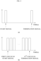
- FIG. 2A shows a V-sync signal generated by the control unit 100 according to an embodiment
- FIG. 2B shows an H-sync signal generated by the control unit 100 according to the embodiment.
- a signal input to the sensor unit 140 by the control unit 100 is illustrated.
- the signal input to the sensor unit 140 by the control unit 100 may be used for acquiring the light intensity value using a rolling shutter method.
- the signal illustrated in FIG. 2A may be a signal input to the sensor unit 140 by the control unit 100 to start or terminate acquiring of the light intensity value.
- the signal for starting or terminating the acquisition of the light intensity value may be a signal including V-sync.
- V-sync the signal that causes the sensor unit 140 to start or terminate acquiring of the light intensity value
- the V-sync signal may be a signal that causes the sensor unit 140 to start or terminate acquiring the light intensity value. That is, when a start signal, which is a V-sync signal, is input to the sensor unit 140, the sensor unit 140 may start to acquire the light intensity value, and when a termination signal is input to the sensor unit 140, the sensor unit 140 may terminate the acquisition of the light intensity value.
- a start signal which is a V-sync signal
- the signal illustrated in FIG. 2B may be a signal input to the sensor unit 140 by the control unit 100 to start acquiring the light intensity value for each line of the sensor unit 140.
- the signal for starting the acquisition of the light intensity value for each line of the sensor unit 140 may be a signal including H-sync.
- H-sync the signal for starting the acquisition of the light intensity value for each line of the sensor unit 140 will be described as an H-sync signal.
- the signal for starting the acquisition of the light intensity value for each line may be expressed as a light-receiving region driving signal, a line scan signal, a region light receiving signal, or the like, but the present invention is not limited thereto, and any expression having the meaning of a signal for starting the acquisition of the light intensity value on the sensor unit 140 may be used.
- the sensor unit 140 may include lines including a first line 320 to an n th line 340. Further, the H-sync signal may include a first line scan start signal to an n th line scan start signal in order to perform a scan for each line of the sensor unit 140.
- the first line scan start signal to the n th line scan start signal of the H-sync signal may be input to the sensor unit 140.
- a termination signal of the V-sync signal may be input to the sensor unit 140.
- FIG. 3 is a diagram illustrating all pixels of the sensor unit 140 according to an embodiment.
- a plurality of pixels may be provided.
- a light intensity value may be acquired from each of the plurality of pixels.
- the sensor unit 140 may start to acquire the light intensity value.
- the control unit 100 may input the H-sync signal to the sensor unit 140.
- light intensity values may be acquired from pixels of each line located on the sensor unit 140.
- the sensor unit 140 may acquire light intensity values from pixels of the first line 320.
- a second line scan start signal to the n th line scan start signal may be sequentially input to the sensor unit 140.
- the sensor unit 140 may acquire light intensity values from pixels of each line from the first line 320 to the n th line 340.
- the control unit 100 may input the termination signal of the V-sync signal to the sensor unit 140.
- the sensor unit 140 may terminate the acquisition of the intensity value of the light returning from the object O.
- the H-sync signal when the start signal of the V-sync signal is input to the sensor unit 140, the H-sync signal may be input to the pixels for each line of the sensor unit 140 so that the intensity value of the light returning from the object O may be acquired, and when the acquisition of the light intensity values for all of the lines is terminated, the termination signal of the V-sync signal may be input to the sensor unit 140 so that the sensor unit 140 may terminate the acquisition of the light intensity values for each line.
- the resolution of the image acquired by the sensor unit 140 using the light returning from the object O may include a resolution of 1280x720, 1920x1080, and 2180 ⁇ 1770, but the present invention is not limited thereto, and images having various resolutions may be acquired based on the number of pixels that the sensor unit 140 may have.
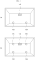
- FIGS. 4A, 4B , 5A, and 5B are schematic diagrams illustrating image scanning devices according to embodiments when viewed from the above.
- the image scanning devices may include one sensor unit 140 and a plurality of lighting units 120.
- the lighting units 120 may include a plurality of lighting devices.
- the sensor unit 140 may be disposed at the center of the image scanning device or at the center of the object O in order to symmetrically acquire light returning from the object O.
- the lighting units 120 of the image scanning device may include a first lighting device 122 and a second lighting device 124.
- the first lighting device 122 and the second lighting device 124 may be present at positions symmetrical to each other with respect to the sensor unit 140. That is, the first lighting device 122 and the second lighting device 124 irradiate opposite side surfaces of the object O with respect to the sensor unit 140 with light.
- the positions of the first lighting device 122 and the second lighting device 124 may be determined based on the position of the sensor unit 140.
- the image scanning device may include a plurality of lighting devices that are symmetrical to each other with respect to the sensor unit 140.
- the lighting units 120 may include a first lighting device 122 to a fourth lighting device 128.
- the first lighting device 122 and the third lighting device 126 may irradiate the same side surface of the object O with light
- the second lighting device 124 and the fourth lighting device 128 may also irradiate the same side surface of the object O with light.
- the first lighting device 122 and the third lighting device 126 may irradiate one side surface of the object O with the light and the second lighting device 124 and the fourth lighting device 128 may irradiate another side surface of the object O with the light
- the first lighting device 122 and the third lighting device 126 may correspond to one lighting unit 120
- the second lighting device 124 and the fourth lighting device 128 may also correspond to one lighting unit 120.
- the plurality of lighting devices may correspond to one lighting unit 120.
- the lighting units 120 may include a plurality of lighting devices in order to apply light to a plurality of regions of the object O.
- the lighting devices may be bilaterally symmetrically disposed with respect to the sensor unit 140 in order to apply light to the object O.
- the number of lighting devices illustrated in FIG. 5A is not limited, and the plurality of lighting devices may be disposed inside the image scanning device so as to be bilaterally symmetrical to each other with respect to the sensor unit 140.
- the lighting unit 120 may be installed to be movable in the image scanning device.
- the movable lighting unit 120 may be moved according to a signal input to the sensor unit 140 by the control unit 100 and may irradiate the object O with light.
- the lighting units 120 will be described as including two lighting devices and the two lighting devices will be described as irradiating the regions symmetrical to each other with respect to the sensor unit 140 with the light.
- control unit 100 may input a lighting control signal to the lighting unit 120 so that the lighting unit 120 sequentially irradiates the object O with light.
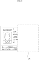
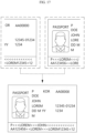
- FIGS. 6 to 8 are diagrams illustrating an image of an object O and images of the object O acquired when a light saturation phenomenon occurs according to an embodiment.
- the sensor unit 140 may acquire an image in a state in which some regions of the image of the object O are light saturated regions. In other words, the first lighting device 122 may generate light saturated regions in some regions of the image of the object O acquired by the sensor unit 140.
- the sensor unit 140 may acquire an image in a state in which some regions of the image of the object O are light saturated regions. In other words, the second lighting device 124 may generate light saturated regions in some regions of the image of the object O acquired by the sensor unit 140.
- the first lighting device 122 and the second lighting device 124 irradiate light to the object O may be different from each other. Accordingly, when each of the first lighting device 122 and the second lighting device 124 irradiates the object O with the light, the image of the object O acquired by the sensor unit 140 may have different light saturated regions. In other words, the first lighting device 122 and the second lighting device 124 may generate the light saturated regions in different regions of the image of the object O acquired by the sensor unit 140.
- the light saturation phenomenon may mean that the light intensity value acquired by each pixel of the sensor unit 140 is greater than a maximum light intensity value that may be acquired by the pixel of the sensor unit 140.
- the light intensity value that may be acquired by the pixel of the sensor unit 140 may vary according to the type of image sensor used as the sensor unit 140. For example, when the maximum light intensity value that may be acquired by the pixel of the sensor unit 140 is 5 and the intensity value of light returning from the object O is 10, the intensity value of the light returning from the object O may not be properly acquired by the pixel of the sensor unit 140, and thus some regions of the image generated by the image generating device may have light saturated regions.
- the region of the object O in which the light saturated region is not present may be a region (hereinafter, referred to as an effective region) in which the control unit 100 may acquire the image of the object O without distortion.
- the control unit 100 acquiring the image of the object O without distortion may mean that the control unit 100 may acquire and output the image of the object O without a light saturated region.
- control unit 100 may acquire the image of the object O without distortion only when the control unit 100 acquires the image of the object O in the effective region other than the light saturated region.
- FIG. 9 is a flowchart illustrating a method S1000 of sequentially controlling the lighting units 120 by the control unit 100 according to an embodiment.
- the method S1000 of sequentially controlling the lighting units 120 by the control unit 100 may include an operation S1200 of inputting an operation signal to the first lighting device 122, an operation S1400 of acquiring, by the sensor unit 140, a light intensity value, an operation S1600 of inputting an operation termination signal to the first lighting device 122 and inputting an operation signal to the second lighting device 124, and an operation S1800 of acquiring, by the sensor unit 140, a light intensity value.
- the operation S1200 of inputting the operation signal to the first lighting device 122 may include inputting, by the control unit 100, the operation signal to the lighting units 120.
- the lighting unit 120 may include the first lighting device 122 and the second lighting device 124, and the control unit 100 may first input the operation signal to the first lighting device 122 among the first lighting device 122 and the second lighting device 124.
- the operation signal refers to a signal input by the control unit 100 so that the lighting unit 120 irradiates the object O with light.
- the lighting unit 120 may receive the operation signal from the control unit 100 once in order to irradiate the object O with the light. In this case, in order for the lighting unit 120 to terminate the light irradiation to the object O, the control unit 100 may input the operation termination signal to the lighting unit 120.
- the lighting unit 120 may continuously receive the operation signal from the control unit 100 in order to irradiate the object O with the light.
- the control unit 100 may stop the inputting of the operation signal to the lighting unit 120.
- the control unit 100 stopping the input of the operation signal to the lighting unit 120 means that the control unit 100 inputs the operation termination signal.
- the first lighting device 122 When the first lighting device 122 receives the operation signal from the control unit 100, the first lighting device 122 may irradiate the object O with the light. In this case, the light applied to the regions of the object O may have different intensity values for each region. Accordingly, the light returning from the object O may have different intensity values for each region.
- the operation S1400 of acquiring, by the sensor unit 140, the light intensity value includes acquiring, by the sensor unit 140, the intensity values of the light returning from the object O.
- the light intensity values of the light returning from the object O may be different for each region of the sensor unit 140.
- the operation S1600 of inputting the operation termination signal to the first lighting device 122 and inputting the operation signal to the second lighting device 124 may include inputting, by the control unit 100, a signal that causes the first lighting device 122 to no longer irradiate the object O with the light, terminating the light irradiation to the object O by the first lighting device 122 according to input of the signal, and inputting, by the control unit 100, a signal that causes the second lighting device 124 to irradiate the object O with the light to the second lighting device 124.
- control unit 100 inputting the operation termination signal to the first lighting device 122 and then inputting the operation signal to the second lighting device 124 the control unit 100 inputting the operation termination signal to some lighting devices of the plurality of lighting devices present in the lighting unit 120 and inputting the operation signal to other lighting devices is expressed as switching the lighting units 120.
- the switching the lighting units may occur after the operation S1400 of acquiring, by the sensor unit 140, the light intensity value, but the present invention is not limited thereto, and the switching the lighting units 120 may occur while the sensor unit 140 acquires the light intensity value. That is, the operations of the acquiring of the light intensity value performed before and after the switching the lighting unit may be a continuous operation performed before and after a time point at which the lighting units are switched. In other words, the lighting units 120 may be switched at one of the time points at which the sensor unit 140 continuously acquires the light intensity values.
- the operation of acquiring the intensity value of the light returning from the object O by the sensor unit 140 described above may be applied to the operation S1800 of acquiring, by the sensor unit 140, the light intensity value.
- the method S1000 may include inputting, by the control unit 100, a signal for terminating the operation of the second lighting device 124 to the lighting unit 120 after the operation of, by the sensor unit 140, acquiring the light intensity value.
- control unit 100 may sequentially switch the lighting units 120.
- control unit 100 may switch the lighting units 120 according to the time points at which the lighting units 120 are to be switched.
- the time points at which the lighting units 120 are to be switched may be determined based on an H-sync or V-sync signal input to the sensor unit 140 by the control unit 100.
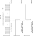
- FIG. 10 is a diagram illustrating a correlation between H-sync signals input to the sensor unit 140 and signals input to the lighting units 120 according to an embodiment
- a horizontal axis of each graph represents time
- a vertical axis represents a numerical value that may identify whether signals including a voltage, a current, and the like are input.
- each signal in the H-sync signal graph represents one of a first line scan start signal to an n th line scan start signal.
- the signals input to the first lighting device 122 and the signals input to the second lighting device 124 represent operation signals of the lighting devices input to the lighting device.
- the control unit 100 may operate the first lighting device 122 and the second lighting device 124 of the lighting units 120 at different time points.
- the control unit 100 may determine a time point at which the operation signals are switched from the first lighting device 122 to the second lighting device 124 on the basis of the signals input to the sensor unit 140.
- FIG. 11 is a diagram illustrating the operation of the lighting units 120 when the sensor unit 140 acquires the image of the object O according to the H-sync signal input according to an embodiment.
- FIG. 12 is a diagram illustrating that, in the correlation between the H-sync signal input to the sensor unit 140 and the signal input to the lighting unit 120, the H-sync signal is input but there is no signal which is input to the lighting unit 120 near a switching time point ST according to an embodiment.
- the switching time point ST at which the control unit 100 switches the operation signals of the lighting devices may be determined by the number of lighting devices.
- the switching time point ST may be one time point less than the number of lighting devices.
- the time point at which the control unit 100 switches the first lighting device 122 and the second lighting device 124 may be a time point at which the first lighting device 122 starts to display the light saturated region.
- the light saturated region may be located in a lower end portion LR of the object O.
- the lower end portion LR refers to a lower region of the drawing for convenience of description and, on the contrary, an upper end portion UR refers to an upper region of the drawing for convenience of description.
- the control unit 100 may acquire an image of the upper end portion UR of the object O in order to acquire the image of the object O.
- control unit 100 may acquire an image of the lower end portion LR of the object O in order to acquire the image of the object O.
- the control unit 100 may use the H-sync signal, which is a signal input to the sensor unit 140.
- the H-sync signal may include the line scan start signal so that the sensor unit 140 acquires the image of the object O for each line.
- the operation signal of the lighting unit 120 may be input based on the input of a plurality of lines scan start signals of the H-sync signal.
- operation signals of the lighting devices may be switched when the H-sync signal inputs the line scan start signal for scanning an intermediate portion of the object O.
- the switching time point ST may be a time point at which the line scan start signal for scanning the intermediate portion of the object O among the plurality of line scan start signals included in the H-sync signal is input to the sensor unit 140.
- a time point at which an (n/2) th line scan start signal (n is an even number) or an ((n+1)/2) th or ((n-1)/2) th line scan start signal (n is odd number), which is the line scan start signal for scanning the intermediate portion of the object O, is input to the sensor unit 140 may be the switching time point ST of the operation signals of the lighting devices.
- the switching time point ST may be a time point at which each of the lighting devices included in the lighting unit 120 generates the light saturated region.
- the switching time point ST may be a time point at which an (n/3) th line scan start signal (when n/3 is not an integer, it is the nearest integer) of the H-sync signal is input and a time point at which an (2*n/3) th line scan start signal (when 2*n/3 is not an integer, it is the nearest integer) is input. That is, when there are a plurality of lighting devices, the switching time point ST may be present in each of time intervals acquired by dividing the plurality of line scan start signals included in the H-sync signal into time intervals in which the plurality of lighting devices are present.
- the control unit 100 may switch the operation signals of the lighting devices of the lighting unit 120. This is because, when the control unit 100 inputs the operation signals of the lighting devices to the lighting unit 120, an actual operation time point of the lighting unit 120 may be a time point later than the time point at which the control unit 100 inputs the operation signals of the lighting devices. Therefore, the switching time points ST of the operation signals of the lighting devices may be determined in consideration of the actual operation time point of the lighting device after inputting the operation signals of the lighting devices.
- the control unit 100 may input the H-sync signal to the sensor unit 140 in a state in which the control unit 100 does not input the operation signals of the lighting devices to both of the first lighting device 122 and the second lighting device 124.
- the operation signal of the second lighting device 124 is not input immediately after the signal for terminating the operation of the first lighting device 122 is input but may be input after a predetermined time has elapsed.
- the control unit 100 may not input any lighting device operation signal to the lighting unit 120.
- the sensor unit 140 performs a scan on the object O for each line of the sensor unit 140 on the basis of the H-sync signal, a time point at which the lighting unit 120 does not input any signal from the control unit 100 may be present.
- control unit 100 inputs the signal for terminating the operation of the first lighting device 122 to the lighting unit 120 and inputs the operation signal of the second lighting device 124 to the lighting unit 120 at the switching time point ST.
- FIG. 13A is a diagram illustrating the intensity of light irradiated by the first lighting device 122 over time according to an example which does not fall within the scope of the claims
- FIG. 13B is a diagram illustrating the intensity of light acquired at each position in the sensor unit 140 when only the first lighting device 122 is operated according to the example which does not fall within the scope of the claims.
- FIGS. 14 and 15 are diagrams illustrating that the sensor unit 140 acquires the image of the object O having a constant light intensity by gradually adjusting the intensity of light irradiated by the lighting unit 120 according to an embodiment.
- FIG. 14A is a graph showing that the intensity of the light applied by the first lighting device 122 gradually and linearly decreases to the switching time point ST according to an embodiment
- FIG. 14B is a graph showing that the light intensity acquired by the sensor unit 140 when the intensity of the light applied by the first lighting device 122 gradually and linearly decreases.
- FIG. 15A is a graph showing that the intensity of the light applied by the first lighting device 122 exponentially decreases to the switching time point ST according to an embodiment
- FIG. 15B is a graph showing that the light intensity acquired by the sensor unit 140 when the intensity of the light applied by the first lighting device 122 exponentially decreases.
- FIGS. 13A , 14A , and 15A a horizontal axis represents time and a vertical axis represents the intensity of light with which the lighting unit 120 irradiates the object O.
- FIGS. 13B , 14B , and 15B illustrate the light intensity acquired in each region of the image of the object O acquired by the sensor unit 140.
- the image of the object O acquired by the sensor unit 140 may correspond to a light saturated region from the intermediate end portion MR to the lower end portion LR.
- the light intensity acquired by the sensor unit 140 is predetermined so that the intensity of the light may be a constant intensity when the intensity of the light returning from the object O is greater than or equal to a predetermined level.
- the acquired intensity of the light may be increased in a direction from the upper end portion UR toward the intermediate end portion MR of the image of the object O acquired by the sensor unit 140.
- the image of the object O acquired by the sensor unit 140 may correspond to a light saturated region from the upper end portion UR to the intermediate end portion MR, and the acquired intensity of the light may be increased in a direction from the lower end portion LR toward the intermediate end portion MR.
- control unit 100 may irradiate the object O with the light by adjusting the intensity of the light when the lighting unit 120 irradiates the object O with the light.
- the lighting unit 120 may linearly decrease the intensity of the light applied to the object O to the switching time point ST. Accordingly, the image of the object O acquired by the sensor unit 140 may exhibit the constant intensity of the light from the upper end portion UR to the intermediate end portion MR of the image. More specifically, when the sensor unit 140 performs a line scan from the upper end portion UR to the lower end portion LR according to the input of the H-sync signal, the lighting unit 120 may linearly decrease the intensity of the light according to an input time of the line scan start signal in order to avoid the light saturated region.
- the second lighting device 124 may linearly increase the intensity of the light applied to the object O after the switching time point ST. Accordingly, the image of the object O acquired by the sensor unit 140 may exhibit the constant intensity of the light from the intermediate end portion MR to the lower end portion LR of the image.
- the lighting unit 120 may exponentially decrease the intensity of the light applied to the object O to the switching time point ST. Accordingly, the image of the object O acquired by the sensor unit 140 may exhibit the constant intensity of the light from the upper end portion UR to the intermediate end portion MR of the image. More specifically, when the sensor unit 140 performs a line scan from the upper end portion UR to the lower end portion LR according to the input of the H-sync signal, the lighting unit 120 may exponentially decrease the intensity of the light according to the input time of the line scan start signal in order to avoid the light saturated region.
- the second lighting device 124 may exponentially increase the intensity of the light applied to the object O after the switching time point ST. Accordingly, the image of the object O acquired by the sensor unit 140 may exhibit the constant intensity of the light from the intermediate end portion MR to the lower end portion LR of the image.
- the exponentially increasing or decreasing includes increasing or decreasing the intensity of the light according to an exponential function or includes increasing or decreasing the intensity of the light in each region acquired by the sensor unit 140 when the lighting unit 120 irradiates the object O with the light with the constant intensity of the light. That is, the meaning of exponential does not mean only a simple exponential function but may mean increasing or decreasing in a non-linear form.
- the lighting unit 120 is described as gradually changing the intensity of the light applied to the object O, but the present invention is not limited thereto, and it is also possible for the control unit 100 to gradually control the signal input to the lighting unit 120 so that the lighting unit 120 gradually changes the intensity of the light.
- control unit 100 may also adjust the intensity of the light returning from the object O acquired by the sensor unit 140.
- FIG. 16 is a flowchart illustrating a process in which the control unit 100 adjusts the intensity of light of the image of the object O acquired by the sensor unit 140 according to an embodiment.
- the adjusting, by the control unit 100, the intensity of the light of the image of the object O acquired by the sensor unit 140 may include acquiring, by the sensor unit 140, the intensity of light returning from the object O, adjusting, by the control unit 100, the acquired intensity of the light, and generating, by the control unit 100, an image of the object O.
- the acquiring of, by the sensor unit 140, the intensity of the light returning from the object O includes inputting, by the control unit 100, the H-sync signal to the sensor unit 140 as described above and, accordingly, acquiring, by the sensor unit 140, the intensity of the light returning from the object O for each line of the sensor unit 140.
- the adjusting of, by the control unit 100, the intensity of the light acquired from the sensor unit 140 may include increasing or decreasing the light intensity of the light acquired by the control unit 100.
- control unit 100 may adjust the intensity of the light acquired from the sensor unit 140 uniformly over all the regions or differently for each region so that the acquired image of the object O may exhibit the intensity of the light substantially uniformly over all the regions.
- a light intensity value of the object O acquired by the sensor unit 140 may be increased in a direction toward the intermediate end portion MR of the sensor unit 140, and thus the control unit 100 may adjust the intensity of the light acquired in the intermediate end portion MR of the sensor unit 140 to be lowered.
- control unit 100 may gradually adjust the intensity of the light acquired in the intermediate end portion MR of the sensor unit 140 to be lowered, similar to the control of the lighting unit 120 described above. Specifically, the control unit 100 may change the intensity of the light acquired from the sensor unit 140 from a region corresponding to the upper end portion UR to a region corresponding to the intermediate end portion MR of the sensor unit 140. In this case, a degree to which the control unit 100 changes the intensity of the light may be linearly or exponentially increased from the region corresponding to the upper end portion UR to the region corresponding to the intermediate end portion MR of the sensor unit 140.
- control unit 100 may change the intensity of the light acquired from the sensor unit 140 from the region corresponding to the lower end portion LR to the region corresponding to the intermediate end portion MR of the sensor unit 140.
- a degree to which the control unit 100 changes the intensity of the light may be linearly or exponentially increased from the region corresponding to the lower end portion LR to the region corresponding to the intermediate end portion MR of the sensor unit 140.
- control unit 100 changes the intensity of the light is linearly or exponentially changed as described above.
- control unit 100 may adjust the intensity of the light acquired from the sensor unit 140 to be increased. This is because, when the control unit 100 generates the image according to the intensity of the light acquired from the sensor unit 140, it may not be possible to sufficiently identify the image.
- control unit 100 may adjust the overall intensity of the light acquired from the sensor unit 140 to be increased or adjust the intensity of the light for each region to be increased differently.
- adjusting the intensity of the light for each region to be different may include adjusting the intensity of the light for each region to be linearly or exponentially increased, as described above.
- control unit 100 may adjust the intensity of the light acquired from the sensor unit 140 in some regions to be increased and adjust the intensity of the light in other regions to be decreased. More specifically, the control unit 100 may adjust the intensity of the light in the regions corresponding to the upper end portion UR and the lower end portion LR of the sensor unit 140 to be increased and adjust the intensity of the light in the region corresponding to the intermediate end portion MR of the sensor unit 140 to be decreased.
- the generating of, by the control unit 100, the image includes generating, by the control unit 100, the image by using the intensity of the light which is acquired by adjusting the intensity of the light acquired from the sensor unit 140 overall and/ or for each region, as described above.
- control unit 100 may output the generated image using an output device.
- control unit 100 may detect only the region in which the light saturated region is present and then cause the sensor unit 140 to scan only the corresponding region. Accordingly, the control unit 100 may synthesize the acquired corresponding regions without the light saturated region in the operation of generating the image.
- the detecting of, by the control unit 100, the region in which the light saturated region is present may refer to detecting a region in which all of RGB signal values of the light intensity acquired by the sensor unit 140 are higher than or equal to a predetermined level.
- FIG. 17 is a diagram illustrating that the control unit 100 acquires one image by acquiring only an effective region of the scanned image without switching the lighting units 120 according to the embodiment.
- control unit 100 may acquire and synthesize an effective region of the scanned image after operating only the first lighting device 122 and an effective region of the scanned image after operating only the second lighting device 124 in order to avoid the light saturated region on the acquired image.
- the control unit 100 may acquire the effective regions of the image in which the light saturated regions appear and then synthesize the effective regions to acquire a single entire image.
- the control unit 100 may cause different lighting devices to irradiate the object O with light and thus perform a plurality of scans using the sensor unit 140. Accordingly, the control unit 100 may acquire and synthesize only the effective regions of the image acquired as a result of each scan.
- the control unit 100 may adjust the intensity of the light of the effective regions.
- the adjusting of the intensity of the light of the effective regions may refer to adjusting the entire intensity of the light or adjusting the intensity of the light for each region with different amounts of changes.
- the adjusting of the intensity of the light of the effective regions is the same as described above.
- the method according to the embodiment may be implemented in the form of program instructions that can be performed through various computer units and recorded on computer readable media.
- the computer readable media may include a program instruction, a data file, a data structure, or combinations thereof.
- the program instruction recorded on the computer readable media may be specially designed and prepared for the embodiments of the invention or may be an available well-known instruction for those skilled in the field of computer software.
- Examples of the computer readable media include magnetic media such as a hard disk, a floppy disk, and a magnetic tape, optical media such as a compact disc read only memory (CD-ROM) and a digital video disc (DVD), magneto-optical media such as a floptical disk, and a hardware device, such as a read only memory (ROM), a random access memory (RAM), or a flash memory, that is specially made to store and perform the program instruction.
- Examples of the program instruction include a machine code generated by a compiler and a high-level language code that can be executed in a computer using an interpreter and the like.
- the hardware device may be configured as at least one software module in order to perform operations of embodiments of the present invention and vice versa.
- an image of an object in which a light saturated region is not generated can be acquired by an image generating device using lighting control.
- an image of an object having substantially constant light intensity values in all regions of the image can be acquired by an image generating device using lighting control.
Landscapes
- Engineering & Computer Science (AREA)
- Multimedia (AREA)
- Signal Processing (AREA)
- Theoretical Computer Science (AREA)
- Business, Economics & Management (AREA)
- Strategic Management (AREA)
- Accounting & Taxation (AREA)
- Finance (AREA)
- Development Economics (AREA)
- Physics & Mathematics (AREA)
- General Physics & Mathematics (AREA)
- Entrepreneurship & Innovation (AREA)
- General Engineering & Computer Science (AREA)
- Software Systems (AREA)
- Data Mining & Analysis (AREA)
- Computer Vision & Pattern Recognition (AREA)
- Artificial Intelligence (AREA)
- Computing Systems (AREA)
- Medical Informatics (AREA)
- Evolutionary Computation (AREA)
- Game Theory and Decision Science (AREA)
- Economics (AREA)
- Marketing (AREA)
- General Business, Economics & Management (AREA)
- Mathematical Physics (AREA)
- Human Computer Interaction (AREA)
- General Health & Medical Sciences (AREA)
- Databases & Information Systems (AREA)
- Health & Medical Sciences (AREA)
- Image Input (AREA)
- Facsimile Scanning Arrangements (AREA)
Claims (12)
- Bilderzeugungsvorrichtung, umfassend:eine Stützeinheit, die konfiguriert ist, um ein Objekt zu stützen;eine Bestrahlungseinheit (120), die konfiguriert ist, um das Objekt zu bestrahlen, das auf der Stützeinheit angeordnet ist;eine Lichtempfangseinheit (140), die konfiguriert ist, um Licht zu empfangen, das von dem Objekt zurückkehrt, das auf der Stützeinheit angeordnet ist; undeine Steuereinheit (100), die konfiguriert ist, um ein Lichtbestrahlungssignal zum Steuern der Bestrahlungseinheit (120), ein Lichtempfangsbereichsantriebssignal zum Steuern der Lichtempfangseinheit (140) und ein Bild unter Verwendung des Lichts, das durch die Lichtempfangseinheit (140) empfangen wird, basierend auf dem Lichtempfangsbereichsantriebssignal zu erzeugen,wobei die Bestrahlungseinheit (120) eine erste Bestrahlungseinheit (122) zum Bestrahlen eines ersten Bereichs des Objekts mit Licht und eine zweite Bestrahlungseinheit (124) zum Bestrahlen eines zweiten Bereichs des Objekts mit Licht beinhaltet,wobei die erste Bestrahlungseinheit (122) und die zweite Bestrahlungseinheit (124) angeordnet sind, um gegenüberliegende Seiten des Objekts in Bezug auf die Lichtempfangseinheit (140) zu bestrahlen,wobei die Lichtempfangseinheit (140) einen ersten Lichtempfangsbereich und einen zweiten Lichtempfangsbereich beinhaltet,wobei die Lichtempfangseinheit (140) eine Vielzahl von Leitungen mit einer Vielzahl von Lichtintensitätswerterfassungsbereichen beinhaltet,wobei die Lichtempfangseinheit (140) sequentiell eine Vielzahl von Lichtintensitätswerten von der Vielzahl von Leitungen erfasst, undder erste Lichtempfangsbereich und der zweite Lichtempfangsbereich eine Vielzahl von Pixeln beinhalten und an verschiedenen Positionen an der Lichtempfangseinheit angeordnet sind,wobei das Lichtbestrahlungssignal ein erstes Lichtbestrahlungssignal zum Steuern der ersten Bestrahlungseinheit (122) und ein zweites Lichtbestrahlungssignal zum Steuern der zweiten Bestrahlungseinheit (124) beinhaltet,wobei das Lichtempfangsbereichsantriebssignal ein erstes Lichtempfangsbereichsantriebssignal zum Antreiben des ersten Lichtempfangsbereichs und ein zweites Lichtempfangsbereichsantriebssignal zum Antreiben des zweiten Lichtempfangsbereichs beinhaltet,wobei der erste Lichtempfangsbereich in Bezug auf die erste Lichtbestrahlungseinheit (122) arbeitet und der zweite Lichtempfangsbereich in Bezug auf die zweite Lichtbestrahlungseinheit (124) arbeitet,wobei die Steuereinheit (100) konfiguriert ist, um das erste Lichtbestrahlungssignal und das erste Lichtempfangsbereichsantriebssignal zu erzeugen und das zweite Lichtbestrahlungssignal und das zweite Lichtempfangsbereichsantriebssignal zu erzeugen, um zu verhindern, dass ein Lichtsättigungsphänomen in der Lichtempfangseinheit (140) auftritt, das durch das Antreiben der Bestrahlungseinheit (120) bewirkt wird,dadurch gekennzeichnet, dassdie erste Bestrahlungseinheit (122) allmählich eine Intensität des Lichts verringert, das auf das Objekt gestrahlt wird, das auf der Stützeinheit angeordnet ist, unddie zweite Bestrahlungseinheit (124) allmählich eine Intensität des Lichts erhöht, das auf das Objekt gestrahlt wird, das auf der Stützeinheit angeordnet ist.
- Bilderzeugungsvorrichtung nach Anspruch 1, wobei Positionen der ersten Bestrahlungseinheit und der zweiten Bestrahlungseinheit basierend auf einer Position der Lichtempfangseinheit in der Bilderzeugungsvorrichtung bestimmt werden.
- Bilderzeugungsvorrichtung nach Anspruch 1, wobei das zweite Lichtbestrahlungssignal in die zweite Bestrahlungseinheit eingegeben wird, nachdem das erste Lichtbestrahlungssignal in die erste Bestrahlungseinheit eingegeben wird.
- Bilderzeugungsvorrichtung nach einem der Ansprüche 1 bis 3, wobei, nachdem das Lichtempfangsbereichsantriebssignal in die Lichtempfangseinheit eingegeben wird, das Lichtbestrahlungssignal in die Bestrahlungseinheit eingegeben wird.
- Bilderzeugungsvorrichtung nach einem der Ansprüche 1 bis 3, wobei, nachdem das Lichtbestrahlungssignal in die Bestrahlungseinheit eingegeben wird, das Lichtempfangsbereichsantriebssignal in die Lichtempfangseinheit eingegeben wird.
- Bilderzeugungsvorrichtung nach Anspruch 1,wobei die erste Bestrahlungseinheit die Intensität des gestrahlten Lichts linear verringert; undwobei die zweite Bestrahlungseinheit die Intensität des gestrahlten Lichts linear erhöht.
- Bilderzeugungsvorrichtung nach Anspruch 1,wobei die erste Bestrahlungseinheit die Intensität des gestrahlten Lichts exponentiell verringert; undwobei die zweite Bestrahlungseinheit die Intensität des gestrahlten Lichts exponentiell erhöht.
- Bilderzeugungsvorrichtung nach Anspruch 3, wobei das zweite Lichtbestrahlungssignal in die zweite Bestrahlungseinheit eingegeben wird, nachdem die Eingabe des ersten Lichtbestrahlungssignals in die erste Bestrahlungseinheit abgeschlossen ist.
- Bilderzeugungsvorrichtung nach Anspruch 8, wobei ein vorbestimmtes Zeitintervall zwischen einem Zeitpunkt, zu dem die Eingabe des ersten Lichtbestrahlungssignals in die erste Bestrahlungseinheit beendet ist, und einem Zeitpunkt, zu dem das zweite Lichtbestrahlungssignal in die zweite Bestrahlungseinheit eingegeben wird, vorhanden ist.
- Bilderzeugungsvorrichtung nach einem der vorhergehenden Ansprüche,
wobei die Steuereinheit konfiguriert ist, um eine Intensität des Lichts, das von jedem Bereich der Lichtempfangseinheit erfasst wird, zu erhöhen oder zu verringern. - Bilderzeugungsverfahren, umfassend:Stützen, durch eine Stützeinheit, eines Objekts;Bestrahlen, durch eine Bestrahlungseinheit (120), des Objekts, das auf der Stützeinheit angeordnet ist, mit Licht;Empfangen, durch eine Lichtempfangseinheit (140), von Licht, das von dem Objekt zurückkehrt, das auf der Stützeinheit angeordnet ist; undErzeugen, durch eine Steuereinheit (100), eines Lichtbestrahlungssignals zum Steuern der Bestrahlungseinheit (120), eines Lichtempfangsbereichsantriebssignals zum Steuern der Lichtempfangseinheit (140) und eines Bildes unter Verwendung des Lichts, das durch die Lichtempfangseinheit (140) empfangen wird, basierend auf dem Lichtempfangsbereichsantriebssignal,wobei die Bestrahlungseinheit (120) eine erste Bestrahlungseinheit (122) zum Bestrahlen eines ersten Bereichs des Objekts mit Licht und eine zweite Bestrahlungseinheit (124) zum Bestrahlen eines zweiten Bereichs des Objekts mit Licht beinhaltet,wobei die erste Bestrahlungseinheit (122) und die zweite Bestrahlungseinheit (124) angeordnet sind, um gegenüberliegende Seiten des Objekts in Bezug auf die Lichtempfangseinheit (140) zu bestrahlen,wobei die Lichtempfangseinheit (140) einen ersten Lichtempfangsbereich und einen zweiten Lichtempfangsbereich beinhaltet,wobei der erste Lichtempfangsbereich und der zweite Lichtempfangsbereich eine Vielzahl von Pixeln beinhalten und an verschiedenen Positionen an der Lichtempfangseinheit (140) angeordnet sind,wobei die Lichtempfangseinheit (140) eine Vielzahl von Leitungen mit einer Vielzahl von Lichtintensitätswerterfassungsbereichen beinhaltet,wobei die Lichtempfangseinheit (140) sequentiell eine Vielzahl von Lichtintensitätswerten von der Vielzahl von Leitungen erfasst,wobei das Lichtbestrahlungssignal ein erstes Lichtbestrahlungssignal zum Steuern der ersten Bestrahlungseinheit (122) und ein zweites Lichtbestrahlungssignal zum Steuern der zweiten Bestrahlungseinheit (124) beinhaltet,wobei das Lichtempfangsbereichsantriebssignal ein erstes Lichtempfangsbereichsantriebssignal zum Antreiben des ersten Lichtempfangsbereichs und ein zweites Lichtempfangsbereichsantriebssignal zum Antreiben des zweiten Lichtempfangsbereichs beinhaltet,wobei der erste Lichtempfangsbereich in Bezug auf die erste Lichtbestrahlungseinheit (122) arbeitet und der zweite Lichtempfangsbereich in Bezug auf die zweite Lichtbestrahlungseinheit (124) arbeitet,wobei die Steuereinheit (100) konfiguriert ist, um das erste Lichtbestrahlungssignal und das erste Lichtempfangsbereichsantriebssignal zu erzeugen und das zweite Lichtbestrahlungssignal und das zweite Lichtempfangsbereichsantriebssignal zu erzeugen, um zu verhindern, dass ein Lichtsättigungsphänomen in der Lichtempfangseinheit (140) auftritt, das durch das Antreiben der Bestrahlungseinheit (120) bewirkt wird,dadurch gekennzeichnet, dassdie erste Bestrahlungseinheit (122) allmählich eine Intensität des Lichts verringert, das auf das Objekt gestrahlt wird, das auf der Stützeinheit angeordnet ist, unddie zweite Bestrahlungseinheit (124) allmählich eine Intensität des Lichts erhöht, das auf das Objekt gestrahlt wird, das auf der Stützeinheit angeordnet ist.
- Computerprogramm, das computerausführbare Anweisungen enthält, um zu bewirken, dass die Vorrichtung nach Anspruch 1 die Schritte des Verfahrens nach Anspruch 11 ausführt.
Applications Claiming Priority (1)
| Application Number | Priority Date | Filing Date | Title |
|---|---|---|---|
| KR1020200100698A KR102405494B1 (ko) | 2020-08-11 | 2020-08-11 | 조명 제어를 이용하는 이미지 생성 장치 |
Publications (3)
| Publication Number | Publication Date |
|---|---|
| EP3965409A1 EP3965409A1 (de) | 2022-03-09 |
| EP3965409B1 true EP3965409B1 (de) | 2025-03-12 |
| EP3965409C0 EP3965409C0 (de) | 2025-03-12 |
Family
ID=76942953
Family Applications (1)
| Application Number | Title | Priority Date | Filing Date |
|---|---|---|---|
| EP21185943.4A Active EP3965409B1 (de) | 2020-08-11 | 2021-07-15 | Bilderzeugungsvorrichtung, bilderzeugungsverfahren und computerprogramm zur durchführung des bilderzeugungsverfahrens |
Country Status (3)
| Country | Link |
|---|---|
| US (2) | US11546522B2 (de) |
| EP (1) | EP3965409B1 (de) |
| KR (1) | KR102405494B1 (de) |
Family Cites Families (14)
| Publication number | Priority date | Publication date | Assignee | Title |
|---|---|---|---|---|
| JP2003189064A (ja) * | 2001-12-14 | 2003-07-04 | Nikon Corp | 固体撮像素子および画像入力装置 |
| JP2005236513A (ja) * | 2004-02-18 | 2005-09-02 | Fujinon Corp | 撮像装置 |
| JP4556993B2 (ja) * | 2007-12-07 | 2010-10-06 | セイコーエプソン株式会社 | 状態検査システム |
| US8011584B2 (en) * | 2008-12-12 | 2011-09-06 | The Code Corporation | Graphical code readers that are configured for glare reduction |
| US7991281B1 (en) * | 2010-03-19 | 2011-08-02 | Hewlett-Packard Development Company, L.P. | Illumination source having programmable rise and fall times |
| KR101349560B1 (ko) * | 2012-04-26 | 2014-01-10 | 엘지이노텍 주식회사 | 적외선 카메라 및 이의 동작 방법 |
| US8743426B2 (en) * | 2012-06-27 | 2014-06-03 | 3M Innovative Properties Company | Image enhancement methods |
| KR101642480B1 (ko) * | 2014-10-01 | 2016-07-28 | 한국원자력연구원 | 저시정 환경에 강한 영상 획득 장치 |
| KR102372088B1 (ko) * | 2015-10-29 | 2022-03-08 | 삼성전자주식회사 | 영상 획득 장치 및 영상 획득 방법 |
| JP6746318B2 (ja) * | 2016-01-22 | 2020-08-26 | ヒューレット−パッカード デベロップメント カンパニー エル.ピー.Hewlett‐Packard Development Company, L.P. | 画像形成装置 |
| US9892299B1 (en) * | 2016-12-09 | 2018-02-13 | Symbol Technologies, Llc | Module and system for, and method of, electro-optically reading a target with reduced specular reflection |
| WO2019054031A1 (ja) * | 2017-09-15 | 2019-03-21 | 富士フイルム株式会社 | 撮像制御装置、撮像装置、撮像制御方法、及び撮像制御プログラム |
| JPWO2020031717A1 (ja) * | 2018-08-07 | 2021-09-09 | ソニーグループ株式会社 | 撮像システム、制御装置、および制御方法 |
| US20200288965A1 (en) * | 2019-03-11 | 2020-09-17 | Spring Biomed Vision Ltd. | System and method for enhanced imaging of biological tissue |
-
2020
- 2020-08-11 KR KR1020200100698A patent/KR102405494B1/ko active Active
-
2021
- 2021-07-15 EP EP21185943.4A patent/EP3965409B1/de active Active
- 2021-08-03 US US17/393,023 patent/US11546522B2/en active Active
-
2022
- 2022-12-12 US US18/079,561 patent/US11836588B2/en active Active
Also Published As
| Publication number | Publication date |
|---|---|
| KR20220020471A (ko) | 2022-02-21 |
| EP3965409A1 (de) | 2022-03-09 |
| US11836588B2 (en) | 2023-12-05 |
| US20220053116A1 (en) | 2022-02-17 |
| KR102405494B1 (ko) | 2022-06-08 |
| US20230110934A1 (en) | 2023-04-13 |
| US11546522B2 (en) | 2023-01-03 |
| EP3965409C0 (de) | 2025-03-12 |
Similar Documents
| Publication | Publication Date | Title |
|---|---|---|
| US11516391B2 (en) | Multiple camera system for wide angle imaging | |
| EP3429189B1 (de) | Dualbilderfassungsverarbeitung | |
| US8792019B2 (en) | Video creation device, video creation method and non-transitory computer-readable storage medium | |
| US20130021504A1 (en) | Multiple image processing | |
| KR102424984B1 (ko) | 복수 개의 카메라를 포함하는 전자 장치 및 그 동작 방법 | |
| US9554029B2 (en) | Imaging apparatus and focus control method | |
| US12250465B2 (en) | Systems, methods, and devices for processing image data from multiple image sensors | |
| JP4060295B2 (ja) | 画像を表すデータを生成するための方法及び装置 | |
| WO2018099060A1 (en) | Method and apparatus for shooting image and terminal device | |
| US10270980B2 (en) | Image capture control apparatus, image capture apparatus, and method of controlling image capture apparatus | |
| US12363436B2 (en) | Imaging apparatus capable of changing thinning-out rates for different angles of view | |
| JP2001109422A (ja) | 動き検出画像制御機能を有するccd書画カメラ付き液晶プロジェクタ | |
| US11836588B2 (en) | Image generating device using lighting control | |
| CN116648717B (zh) | 多传感器设备中的相机传感器改变 | |
| CN118587404A (zh) | 具有画中画图像输出的多传感器系统 | |
| US11429229B2 (en) | Image processing apparatus and display apparatus with detection function | |
| JP2011151454A (ja) | 画像処理装置、撮像機器及び画像処理方法 | |
| US20250386102A1 (en) | Focusing a multiple-camera system | |
| WO2024118403A1 (en) | Image sensor with multiple image readout | |
| JP5089499B2 (ja) | 撮影装置、動画静止画記録方法 | |
| HK1179790A (en) | Dual image capture processing |
Legal Events
| Date | Code | Title | Description |
|---|---|---|---|
| PUAI | Public reference made under article 153(3) epc to a published international application that has entered the european phase |
Free format text: ORIGINAL CODE: 0009012 |
|
| STAA | Information on the status of an ep patent application or granted ep patent |
Free format text: STATUS: THE APPLICATION HAS BEEN PUBLISHED |
|
| AK | Designated contracting states |
Kind code of ref document: A1 Designated state(s): AL AT BE BG CH CY CZ DE DK EE ES FI FR GB GR HR HU IE IS IT LI LT LU LV MC MK MT NL NO PL PT RO RS SE SI SK SM TR |
|
| STAA | Information on the status of an ep patent application or granted ep patent |
Free format text: STATUS: REQUEST FOR EXAMINATION WAS MADE |
|
| 17P | Request for examination filed |
Effective date: 20220906 |
|
| RBV | Designated contracting states (corrected) |
Designated state(s): AL AT BE BG CH CY CZ DE DK EE ES FI FR GB GR HR HU IE IS IT LI LT LU LV MC MK MT NL NO PL PT RO RS SE SI SK SM TR |
|
| RAP3 | Party data changed (applicant data changed or rights of an application transferred) |
Owner name: XPERIX INC. |
|
| GRAP | Despatch of communication of intention to grant a patent |
Free format text: ORIGINAL CODE: EPIDOSNIGR1 |
|
| STAA | Information on the status of an ep patent application or granted ep patent |
Free format text: STATUS: GRANT OF PATENT IS INTENDED |
|
| INTG | Intention to grant announced |
Effective date: 20241004 |
|
| RAP3 | Party data changed (applicant data changed or rights of an application transferred) |
Owner name: XPERIX INC. |
|
| GRAS | Grant fee paid |
Free format text: ORIGINAL CODE: EPIDOSNIGR3 |
|
| GRAA | (expected) grant |
Free format text: ORIGINAL CODE: 0009210 |
|
| STAA | Information on the status of an ep patent application or granted ep patent |
Free format text: STATUS: THE PATENT HAS BEEN GRANTED |
|
| AK | Designated contracting states |
Kind code of ref document: B1 Designated state(s): AL AT BE BG CH CY CZ DE DK EE ES FI FR GB GR HR HU IE IS IT LI LT LU LV MC MK MT NL NO PL PT RO RS SE SI SK SM TR |
|
| REG | Reference to a national code |
Ref country code: GB Ref legal event code: FG4D |
|
| REG | Reference to a national code |
Ref country code: CH Ref legal event code: EP |
|
| REG | Reference to a national code |
Ref country code: DE Ref legal event code: R096 Ref document number: 602021027408 Country of ref document: DE |
|
| REG | Reference to a national code |
Ref country code: IE Ref legal event code: FG4D |
|
| PG25 | Lapsed in a contracting state [announced via postgrant information from national office to epo] |
Ref country code: RS Free format text: LAPSE BECAUSE OF FAILURE TO SUBMIT A TRANSLATION OF THE DESCRIPTION OR TO PAY THE FEE WITHIN THE PRESCRIBED TIME-LIMIT Effective date: 20250612 |
|
| PG25 | Lapsed in a contracting state [announced via postgrant information from national office to epo] |
Ref country code: FI Free format text: LAPSE BECAUSE OF FAILURE TO SUBMIT A TRANSLATION OF THE DESCRIPTION OR TO PAY THE FEE WITHIN THE PRESCRIBED TIME-LIMIT Effective date: 20250312 |
|
| PG25 | Lapsed in a contracting state [announced via postgrant information from national office to epo] |
Ref country code: ES Free format text: LAPSE BECAUSE OF FAILURE TO SUBMIT A TRANSLATION OF THE DESCRIPTION OR TO PAY THE FEE WITHIN THE PRESCRIBED TIME-LIMIT Effective date: 20250312 |
|
| REG | Reference to a national code |
Ref country code: LT Ref legal event code: MG9D |
|
| PG25 | Lapsed in a contracting state [announced via postgrant information from national office to epo] |
Ref country code: NO Free format text: LAPSE BECAUSE OF FAILURE TO SUBMIT A TRANSLATION OF THE DESCRIPTION OR TO PAY THE FEE WITHIN THE PRESCRIBED TIME-LIMIT Effective date: 20250612 |
|
| PG25 | Lapsed in a contracting state [announced via postgrant information from national office to epo] |
Ref country code: HR Free format text: LAPSE BECAUSE OF FAILURE TO SUBMIT A TRANSLATION OF THE DESCRIPTION OR TO PAY THE FEE WITHIN THE PRESCRIBED TIME-LIMIT Effective date: 20250312 |
|
| REG | Reference to a national code |
Ref country code: NL Ref legal event code: MP Effective date: 20250312 |
|
| PG25 | Lapsed in a contracting state [announced via postgrant information from national office to epo] |
Ref country code: LV Free format text: LAPSE BECAUSE OF FAILURE TO SUBMIT A TRANSLATION OF THE DESCRIPTION OR TO PAY THE FEE WITHIN THE PRESCRIBED TIME-LIMIT Effective date: 20250312 |
|
| PG25 | Lapsed in a contracting state [announced via postgrant information from national office to epo] |
Ref country code: BG Free format text: LAPSE BECAUSE OF FAILURE TO SUBMIT A TRANSLATION OF THE DESCRIPTION OR TO PAY THE FEE WITHIN THE PRESCRIBED TIME-LIMIT Effective date: 20250312 Ref country code: GR Free format text: LAPSE BECAUSE OF FAILURE TO SUBMIT A TRANSLATION OF THE DESCRIPTION OR TO PAY THE FEE WITHIN THE PRESCRIBED TIME-LIMIT Effective date: 20250613 |
|
| U01 | Request for unitary effect filed |
Effective date: 20250613 |
|
| U50 | Request for re-establishment of rights filed [unitary effect] |
Free format text: RE-ESTABLISHMENT OF RIGHTS REQUESTED DUE TO A LATE FILING ON THE REQUEST FOR UNITARY EFFECT Effective date: 20250613 |
|
| REG | Reference to a national code |
Ref country code: AT Ref legal event code: MK05 Ref document number: 1775993 Country of ref document: AT Kind code of ref document: T Effective date: 20250312 |
|
| U07 | Unitary effect registered |
Designated state(s): AT BE BG DE DK EE FI FR IT LT LU LV MT NL PT RO SE SI Effective date: 20250808 |
|
| U53 | Request for re-establishment of rights accepted [unitary effect] |
Effective date: 20250808 |
|
| PG25 | Lapsed in a contracting state [announced via postgrant information from national office to epo] |
Ref country code: SM Free format text: LAPSE BECAUSE OF FAILURE TO SUBMIT A TRANSLATION OF THE DESCRIPTION OR TO PAY THE FEE WITHIN THE PRESCRIBED TIME-LIMIT Effective date: 20250312 |
|
| PG25 | Lapsed in a contracting state [announced via postgrant information from national office to epo] |
Ref country code: PL Free format text: LAPSE BECAUSE OF FAILURE TO SUBMIT A TRANSLATION OF THE DESCRIPTION OR TO PAY THE FEE WITHIN THE PRESCRIBED TIME-LIMIT Effective date: 20250312 |
|
| PGFP | Annual fee paid to national office [announced via postgrant information from national office to epo] |
Ref country code: GB Payment date: 20250717 Year of fee payment: 5 |
|
| PG25 | Lapsed in a contracting state [announced via postgrant information from national office to epo] |
Ref country code: CZ Free format text: LAPSE BECAUSE OF FAILURE TO SUBMIT A TRANSLATION OF THE DESCRIPTION OR TO PAY THE FEE WITHIN THE PRESCRIBED TIME-LIMIT Effective date: 20250312 |
|
| U20 | Renewal fee for the european patent with unitary effect paid |
Year of fee payment: 5 Effective date: 20250915 |
|
| PG25 | Lapsed in a contracting state [announced via postgrant information from national office to epo] |
Ref country code: SK Free format text: LAPSE BECAUSE OF FAILURE TO SUBMIT A TRANSLATION OF THE DESCRIPTION OR TO PAY THE FEE WITHIN THE PRESCRIBED TIME-LIMIT Effective date: 20250312 |
|
| PG25 | Lapsed in a contracting state [announced via postgrant information from national office to epo] |
Ref country code: IS Free format text: LAPSE BECAUSE OF FAILURE TO SUBMIT A TRANSLATION OF THE DESCRIPTION OR TO PAY THE FEE WITHIN THE PRESCRIBED TIME-LIMIT Effective date: 20250712 |
|
| PLBE | No opposition filed within time limit |
Free format text: ORIGINAL CODE: 0009261 |
|
| STAA | Information on the status of an ep patent application or granted ep patent |
Free format text: STATUS: NO OPPOSITION FILED WITHIN TIME LIMIT |
|
| REG | Reference to a national code |
Ref country code: CH Ref legal event code: L10 Free format text: ST27 STATUS EVENT CODE: U-0-0-L10-L00 (AS PROVIDED BY THE NATIONAL OFFICE) Effective date: 20260121 |
|
| 26N | No opposition filed |
Effective date: 20251215 |
|
| REG | Reference to a national code |
Ref country code: CH Ref legal event code: H13 Free format text: ST27 STATUS EVENT CODE: U-0-0-H10-H13 (AS PROVIDED BY THE NATIONAL OFFICE) Effective date: 20260224 |
|
| PG25 | Lapsed in a contracting state [announced via postgrant information from national office to epo] |
Ref country code: CH Free format text: LAPSE BECAUSE OF NON-PAYMENT OF DUE FEES Effective date: 20250731 |