EP3965353B1 - Method and apparatus for determining feedback resource in nr v2x - Google Patents
Method and apparatus for determining feedback resource in nr v2x Download PDFInfo
- Publication number
- EP3965353B1 EP3965353B1 EP20836869.6A EP20836869A EP3965353B1 EP 3965353 B1 EP3965353 B1 EP 3965353B1 EP 20836869 A EP20836869 A EP 20836869A EP 3965353 B1 EP3965353 B1 EP 3965353B1
- Authority
- EP
- European Patent Office
- Prior art keywords
- psfch
- resource
- pssch
- psfch resource
- group
- Prior art date
- Legal status (The legal status is an assumption and is not a legal conclusion. Google has not performed a legal analysis and makes no representation as to the accuracy of the status listed.)
- Active
Links
- 238000000034 method Methods 0.000 title claims description 94
- 238000004891 communication Methods 0.000 claims description 120
- 230000005540 biological transmission Effects 0.000 claims description 62
- 230000015654 memory Effects 0.000 claims description 49
- 125000004122 cyclic group Chemical group 0.000 claims description 32
- 239000010410 layer Substances 0.000 description 76
- 230000006870 function Effects 0.000 description 29
- 238000013468 resource allocation Methods 0.000 description 19
- 238000005516 engineering process Methods 0.000 description 17
- 230000008569 process Effects 0.000 description 16
- 238000012545 processing Methods 0.000 description 12
- 238000013507 mapping Methods 0.000 description 8
- 238000013473 artificial intelligence Methods 0.000 description 5
- 230000001174 ascending effect Effects 0.000 description 4
- 230000008859 change Effects 0.000 description 4
- 238000001514 detection method Methods 0.000 description 4
- 230000008093 supporting effect Effects 0.000 description 4
- 238000012546 transfer Methods 0.000 description 4
- 239000000969 carrier Substances 0.000 description 3
- 238000012937 correction Methods 0.000 description 3
- 230000000694 effects Effects 0.000 description 3
- 238000007726 management method Methods 0.000 description 3
- 230000000737 periodic effect Effects 0.000 description 3
- 230000008054 signal transmission Effects 0.000 description 3
- 238000012384 transportation and delivery Methods 0.000 description 3
- 101000741965 Homo sapiens Inactive tyrosine-protein kinase PRAG1 Proteins 0.000 description 2
- 102100038659 Inactive tyrosine-protein kinase PRAG1 Human genes 0.000 description 2
- 241000700159 Rattus Species 0.000 description 2
- 230000006978 adaptation Effects 0.000 description 2
- 230000008901 benefit Effects 0.000 description 2
- 230000015556 catabolic process Effects 0.000 description 2
- 238000010586 diagram Methods 0.000 description 2
- 238000005286 illumination Methods 0.000 description 2
- 230000007774 longterm Effects 0.000 description 2
- 238000005259 measurement Methods 0.000 description 2
- 238000010295 mobile communication Methods 0.000 description 2
- 230000004044 response Effects 0.000 description 2
- 238000010187 selection method Methods 0.000 description 2
- 230000011664 signaling Effects 0.000 description 2
- 239000004984 smart glass Substances 0.000 description 2
- 101100514059 Escherichia coli (strain K12) modE gene Proteins 0.000 description 1
- 230000027311 M phase Effects 0.000 description 1
- 108091029480 NONCODE Proteins 0.000 description 1
- 230000003044 adaptive effect Effects 0.000 description 1
- 238000004873 anchoring Methods 0.000 description 1
- 238000003491 array Methods 0.000 description 1
- 230000003190 augmentative effect Effects 0.000 description 1
- 230000001413 cellular effect Effects 0.000 description 1
- 230000006835 compression Effects 0.000 description 1
- 238000007906 compression Methods 0.000 description 1
- 239000000470 constituent Substances 0.000 description 1
- 230000003247 decreasing effect Effects 0.000 description 1
- 238000006731 degradation reaction Methods 0.000 description 1
- 238000013461 design Methods 0.000 description 1
- 239000003814 drug Substances 0.000 description 1
- 230000007613 environmental effect Effects 0.000 description 1
- 238000011156 evaluation Methods 0.000 description 1
- 239000000446 fuel Substances 0.000 description 1
- PCHJSUWPFVWCPO-UHFFFAOYSA-N gold Chemical group [Au] PCHJSUWPFVWCPO-UHFFFAOYSA-N 0.000 description 1
- 230000001976 improved effect Effects 0.000 description 1
- 230000002452 interceptive effect Effects 0.000 description 1
- 239000002346 layers by function Substances 0.000 description 1
- 239000011159 matrix material Substances 0.000 description 1
- 230000007246 mechanism Effects 0.000 description 1
- 230000010363 phase shift Effects 0.000 description 1
- 230000002441 reversible effect Effects 0.000 description 1
- 230000000630 rising effect Effects 0.000 description 1
- 230000011218 segmentation Effects 0.000 description 1
- 239000010454 slate Substances 0.000 description 1
- 238000001228 spectrum Methods 0.000 description 1
- 230000003068 static effect Effects 0.000 description 1
- 230000001960 triggered effect Effects 0.000 description 1
- 238000005406 washing Methods 0.000 description 1
Images


Classifications
-
- H—ELECTRICITY
- H04—ELECTRIC COMMUNICATION TECHNIQUE
- H04L—TRANSMISSION OF DIGITAL INFORMATION, e.g. TELEGRAPHIC COMMUNICATION
- H04L1/00—Arrangements for detecting or preventing errors in the information received
- H04L1/12—Arrangements for detecting or preventing errors in the information received by using return channel
- H04L1/16—Arrangements for detecting or preventing errors in the information received by using return channel in which the return channel carries supervisory signals, e.g. repetition request signals
- H04L1/18—Automatic repetition systems, e.g. Van Duuren systems
-
- H—ELECTRICITY
- H04—ELECTRIC COMMUNICATION TECHNIQUE
- H04L—TRANSMISSION OF DIGITAL INFORMATION, e.g. TELEGRAPHIC COMMUNICATION
- H04L1/00—Arrangements for detecting or preventing errors in the information received
- H04L1/004—Arrangements for detecting or preventing errors in the information received by using forward error control
- H04L1/0045—Arrangements at the receiver end
- H04L1/0055—MAP-decoding
-
- H—ELECTRICITY
- H04—ELECTRIC COMMUNICATION TECHNIQUE
- H04L—TRANSMISSION OF DIGITAL INFORMATION, e.g. TELEGRAPHIC COMMUNICATION
- H04L1/00—Arrangements for detecting or preventing errors in the information received
- H04L1/12—Arrangements for detecting or preventing errors in the information received by using return channel
- H04L1/16—Arrangements for detecting or preventing errors in the information received by using return channel in which the return channel carries supervisory signals, e.g. repetition request signals
- H04L1/18—Automatic repetition systems, e.g. Van Duuren systems
- H04L1/1812—Hybrid protocols; Hybrid automatic repeat request [HARQ]
-
- H—ELECTRICITY
- H04—ELECTRIC COMMUNICATION TECHNIQUE
- H04L—TRANSMISSION OF DIGITAL INFORMATION, e.g. TELEGRAPHIC COMMUNICATION
- H04L1/00—Arrangements for detecting or preventing errors in the information received
- H04L1/12—Arrangements for detecting or preventing errors in the information received by using return channel
- H04L1/16—Arrangements for detecting or preventing errors in the information received by using return channel in which the return channel carries supervisory signals, e.g. repetition request signals
- H04L1/18—Automatic repetition systems, e.g. Van Duuren systems
- H04L1/1829—Arrangements specially adapted for the receiver end
- H04L1/1861—Physical mapping arrangements
-
- H—ELECTRICITY
- H04—ELECTRIC COMMUNICATION TECHNIQUE
- H04L—TRANSMISSION OF DIGITAL INFORMATION, e.g. TELEGRAPHIC COMMUNICATION
- H04L1/00—Arrangements for detecting or preventing errors in the information received
- H04L1/12—Arrangements for detecting or preventing errors in the information received by using return channel
- H04L1/16—Arrangements for detecting or preventing errors in the information received by using return channel in which the return channel carries supervisory signals, e.g. repetition request signals
- H04L1/18—Automatic repetition systems, e.g. Van Duuren systems
- H04L1/1829—Arrangements specially adapted for the receiver end
- H04L1/1854—Scheduling and prioritising arrangements
-
- H—ELECTRICITY
- H04—ELECTRIC COMMUNICATION TECHNIQUE
- H04L—TRANSMISSION OF DIGITAL INFORMATION, e.g. TELEGRAPHIC COMMUNICATION
- H04L5/00—Arrangements affording multiple use of the transmission path
-
- H—ELECTRICITY
- H04—ELECTRIC COMMUNICATION TECHNIQUE
- H04L—TRANSMISSION OF DIGITAL INFORMATION, e.g. TELEGRAPHIC COMMUNICATION
- H04L5/00—Arrangements affording multiple use of the transmission path
- H04L5/003—Arrangements for allocating sub-channels of the transmission path
- H04L5/0032—Distributed allocation, i.e. involving a plurality of allocating devices, each making partial allocation
- H04L5/0033—Distributed allocation, i.e. involving a plurality of allocating devices, each making partial allocation each allocating device acting autonomously, i.e. without negotiation with other allocating devices
-
- H—ELECTRICITY
- H04—ELECTRIC COMMUNICATION TECHNIQUE
- H04L—TRANSMISSION OF DIGITAL INFORMATION, e.g. TELEGRAPHIC COMMUNICATION
- H04L5/00—Arrangements affording multiple use of the transmission path
- H04L5/003—Arrangements for allocating sub-channels of the transmission path
- H04L5/0044—Arrangements for allocating sub-channels of the transmission path allocation of payload
-
- H—ELECTRICITY
- H04—ELECTRIC COMMUNICATION TECHNIQUE
- H04L—TRANSMISSION OF DIGITAL INFORMATION, e.g. TELEGRAPHIC COMMUNICATION
- H04L5/00—Arrangements affording multiple use of the transmission path
- H04L5/003—Arrangements for allocating sub-channels of the transmission path
- H04L5/0053—Allocation of signaling, i.e. of overhead other than pilot signals
- H04L5/0055—Physical resource allocation for ACK/NACK
-
- H—ELECTRICITY
- H04—ELECTRIC COMMUNICATION TECHNIQUE
- H04L—TRANSMISSION OF DIGITAL INFORMATION, e.g. TELEGRAPHIC COMMUNICATION
- H04L5/00—Arrangements affording multiple use of the transmission path
- H04L5/003—Arrangements for allocating sub-channels of the transmission path
- H04L5/0078—Timing of allocation
- H04L5/0082—Timing of allocation at predetermined intervals
-
- H—ELECTRICITY
- H04—ELECTRIC COMMUNICATION TECHNIQUE
- H04L—TRANSMISSION OF DIGITAL INFORMATION, e.g. TELEGRAPHIC COMMUNICATION
- H04L5/00—Arrangements affording multiple use of the transmission path
- H04L5/0091—Signaling for the administration of the divided path
-
- H—ELECTRICITY
- H04—ELECTRIC COMMUNICATION TECHNIQUE
- H04W—WIRELESS COMMUNICATION NETWORKS
- H04W4/00—Services specially adapted for wireless communication networks; Facilities therefor
- H04W4/30—Services specially adapted for particular environments, situations or purposes
- H04W4/40—Services specially adapted for particular environments, situations or purposes for vehicles, e.g. vehicle-to-pedestrians [V2P]
-
- H—ELECTRICITY
- H04—ELECTRIC COMMUNICATION TECHNIQUE
- H04W—WIRELESS COMMUNICATION NETWORKS
- H04W72/00—Local resource management
- H04W72/02—Selection of wireless resources by user or terminal
-
- H—ELECTRICITY
- H04—ELECTRIC COMMUNICATION TECHNIQUE
- H04W—WIRELESS COMMUNICATION NETWORKS
- H04W72/00—Local resource management
- H04W72/04—Wireless resource allocation
-
- H—ELECTRICITY
- H04—ELECTRIC COMMUNICATION TECHNIQUE
- H04W—WIRELESS COMMUNICATION NETWORKS
- H04W72/00—Local resource management
- H04W72/04—Wireless resource allocation
- H04W72/044—Wireless resource allocation based on the type of the allocated resource
- H04W72/0446—Resources in time domain, e.g. slots or frames
-
- H—ELECTRICITY
- H04—ELECTRIC COMMUNICATION TECHNIQUE
- H04W—WIRELESS COMMUNICATION NETWORKS
- H04W72/00—Local resource management
- H04W72/04—Wireless resource allocation
- H04W72/044—Wireless resource allocation based on the type of the allocated resource
- H04W72/0453—Resources in frequency domain, e.g. a carrier in FDMA
-
- H—ELECTRICITY
- H04—ELECTRIC COMMUNICATION TECHNIQUE
- H04W—WIRELESS COMMUNICATION NETWORKS
- H04W72/00—Local resource management
- H04W72/12—Wireless traffic scheduling
- H04W72/1263—Mapping of traffic onto schedule, e.g. scheduled allocation or multiplexing of flows
-
- H—ELECTRICITY
- H04—ELECTRIC COMMUNICATION TECHNIQUE
- H04W—WIRELESS COMMUNICATION NETWORKS
- H04W72/00—Local resource management
- H04W72/20—Control channels or signalling for resource management
-
- H—ELECTRICITY
- H04—ELECTRIC COMMUNICATION TECHNIQUE
- H04W—WIRELESS COMMUNICATION NETWORKS
- H04W72/00—Local resource management
- H04W72/50—Allocation or scheduling criteria for wireless resources
- H04W72/51—Allocation or scheduling criteria for wireless resources based on terminal or device properties
-
- H—ELECTRICITY
- H04—ELECTRIC COMMUNICATION TECHNIQUE
- H04W—WIRELESS COMMUNICATION NETWORKS
- H04W72/00—Local resource management
- H04W72/50—Allocation or scheduling criteria for wireless resources
- H04W72/53—Allocation or scheduling criteria for wireless resources based on regulatory allocation policies
-
- H—ELECTRICITY
- H04—ELECTRIC COMMUNICATION TECHNIQUE
- H04W—WIRELESS COMMUNICATION NETWORKS
- H04W92/00—Interfaces specially adapted for wireless communication networks
- H04W92/16—Interfaces between hierarchically similar devices
- H04W92/18—Interfaces between hierarchically similar devices between terminal devices
-
- G—PHYSICS
- G08—SIGNALLING
- G08G—TRAFFIC CONTROL SYSTEMS
- G08G1/00—Traffic control systems for road vehicles
- G08G1/16—Anti-collision systems
- G08G1/161—Decentralised systems, e.g. inter-vehicle communication
-
- G—PHYSICS
- G08—SIGNALLING
- G08G—TRAFFIC CONTROL SYSTEMS
- G08G1/00—Traffic control systems for road vehicles
- G08G1/16—Anti-collision systems
- G08G1/164—Centralised systems, e.g. external to vehicles
-
- G—PHYSICS
- G08—SIGNALLING
- G08G—TRAFFIC CONTROL SYSTEMS
- G08G1/00—Traffic control systems for road vehicles
- G08G1/22—Platooning, i.e. convoy of communicating vehicles
-
- H—ELECTRICITY
- H04—ELECTRIC COMMUNICATION TECHNIQUE
- H04L—TRANSMISSION OF DIGITAL INFORMATION, e.g. TELEGRAPHIC COMMUNICATION
- H04L1/00—Arrangements for detecting or preventing errors in the information received
- H04L2001/0092—Error control systems characterised by the topology of the transmission link
- H04L2001/0093—Point-to-multipoint
-
- H—ELECTRICITY
- H04—ELECTRIC COMMUNICATION TECHNIQUE
- H04L—TRANSMISSION OF DIGITAL INFORMATION, e.g. TELEGRAPHIC COMMUNICATION
- H04L5/00—Arrangements affording multiple use of the transmission path
- H04L5/0001—Arrangements for dividing the transmission path
- H04L5/0026—Division using four or more dimensions
Definitions
- This disclosure relates to a wireless communication system.
- SL communication is a communication scheme in which a direct link is established between User Equipments (UEs) and the UEs exchange voice and data directly with each other without intervention of an evolved Node B (eNB).
- UEs User Equipments
- eNB evolved Node B
- SL communication is under consideration as a solution to the overhead of an eNB caused by rapidly increasing data traffic.
- V2X Vehicle-to-everything refers to a communication technology through which a vehicle exchanges information with another vehicle, a pedestrian, an object having an infrastructure (or infra) established therein, and so on.
- the V2X may be divided into 4 types, such as vehicle-to-vehicle (V2V), vehicle-to-infrastructure (V2I), vehicle-to-network (V2N), and vehicle-to-pedestrian (V2P).
- V2X communication may be provided via a PCS interface and/or Uu interface.
- RAT Radio Access Technology
- V2X vehicle-to-everything
- FIG. 1 is a drawing for describing V2X communication based on NR, compared to V2X communication based on RAT used before NR.
- V2X communication a scheme of providing a safety service, based on a V2X message such as Basic Safety Message (BSM), Cooperative Awareness Message (CAM), and Decentralized Environmental Notification Message (DENM) is focused in the discussion on the RAT used before the NR.
- the V2X message may include position information, dynamic information, attribute information, or the like.
- a UE may transmit a periodic message type CAM and/or an event triggered message type DENM to another UE.
- the CAM may include dynamic state information of the vehicle such as direction and speed, static data of the vehicle such as a size, and basic vehicle information such as an exterior illumination state, route details, or the like.
- the UE may broadcast the CAM, and latency of the CAM may be less than 100ms.
- the UE may generate the DENM and transmit it to another UE in an unexpected situation such as a vehicle breakdown, accident, or the like.
- all vehicles within a transmission range of the UE may receive the CAM and/or the DENM. In this case, the DENM may have a higher priority than the CAM.
- V2X communication various V2X scenarios are proposed in NR.
- the various V2X scenarios may include vehicle platooning, advanced driving, extended sensors, remote driving, or the like.
- vehicles may move together by dynamically forming a group.
- the vehicles belonging to the group may receive periodic data from a leading vehicle.
- the vehicles belonging to the group may decrease or increase an interval between the vehicles by using the periodic data.
- the vehicle may be semi-automated or fully automated.
- each vehicle may adjust trajectories or maneuvers, based on data obtained from a local sensor of a proximity vehicle and/or a proximity logical entity.
- each vehicle may share driving intention with proximity vehicles.
- raw data, processed data, or live video data obtained through the local sensors may be exchanged between a vehicle, a logical entity, a UE of pedestrians, and/or a V2X application server. Therefore, for example, the vehicle may recognize a more improved environment than an environment in which a self-sensor is used for detection.
- a remote driver or a V2X application may operate or control the remote vehicle.
- a route is predictable such as public transportation
- cloud computing based driving may be used for the operation or control of the remote vehicle.
- an access for a cloud-based back-end service platform may be considered for the remote driving.
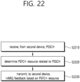
- a UE transmitting a PSSCH may receive a PSFCH related to the PSSCH. Therefore, the UE needs to efficiently determine resource(s) for the PSFCH.
- a method for performing, by a first device, wireless communication is provided as set forth in the appended claims.
- a first device configured to perform wireless communication is provided as set forth in the appended claims.
- the user equipment may efficiently perform SL communication.
- a or B may mean “only A”, “only B” or “both A and B.”
- a or B may be interpreted as “A and/or B”.
- A, B, or C may mean “only A”, “only B”, “only C”, or "any combination of A, B, C”.
- a slash (/) or comma used in the present disclosure may mean “and/or”.
- A/B may mean “A and/or B”.
- A/B may mean “only A”, “only B”, or “both A and B”.
- A, B, C may mean “A, B, or C”.
- At least one of A and B may mean “only A”, “only B”, or “both A and B”.
- the expression “at least one of A or B” or “at least one of A and/or B” may be interpreted as "at least one of A and B”.
- At least one of A, B, and C may mean “only A”, “only B”, “only C”, or “any combination of A, B, and C”.
- at least one of A, B, or C or “at least one of A, B, and/or C” may mean “at least one of A, B, and C”.
- a parenthesis used in the present disclosure may mean “for example”.
- control information PDCCH
- PDCCH control information
- a parenthesis used in the present disclosure may mean “for example”.
- control information i.e., PDCCH
- PDCCH control information
- a technical feature described individually in one figure in the present disclosure may be individually implemented, or may be simultaneously implemented.
- CDMA code division multiple access
- FDMA frequency division multiple access
- TDMA time division multiple access
- OFDMA orthogonal frequency division multiple access
- SC-FDMA single carrier frequency division multiple access
- the CDMA may be implemented with a radio technology, such as universal terrestrial radio access (UTRA) or CDMA-2000.
- UTRA universal terrestrial radio access
- the TDMA may be implemented with a radio technology, such as global system for mobile communications (GSM)/general packet ratio service (GPRS)/enhanced data rate for GSM evolution (EDGE).
- GSM global system for mobile communications
- GPRS general packet ratio service
- EDGE enhanced data rate for GSM evolution
- the OFDMA may be implemented with a radio technology, such as institute of electrical and electronics engineers (IEEE) 802.11 (Wi-Fi), IEEE 802.16 (WiMAX), IEEE 802.20, evolved UTRA (E-UTRA), and so on.
- IEEE 802.16m is an evolved version of IEEE 802.16e and provides backward compatibility with a system based on the IEEE 802.16e.
- the UTRA is part of a universal mobile telecommunication system (UMTS).
- 3rd generation partnership project (3GPP) long term evolution (LTE) is part of an evolved UMTS (E-UMTS) using the E-UTRA.
- the 3GPP LTE uses the OFDMA in a downlink and uses the SC-FDMA in an uplink.
- LTE-advanced (LTE-A) is an evolution of the LTE.
- 5G NR is a successive technology of LTE-A corresponding to a new Clean-slate type mobile communication system having the characteristics of high performance, low latency, high availability, and so on.
- 5G NR may use resources of all spectrum available for usage including low frequency bands of less than 1GHz, middle frequency bands ranging from 1GHz to 10GHz, high frequency (millimeter waves) of 24GHz or more, and so on.
- FIG. 2 shows a structure of an NR system, based on an embodiment of the present disclosure.
- the embodiment of FIG. 2 may be combined with various embodiments of the present disclosure.
- a next generation-radio access network may include a BS 20 providing a UE 10 with a user plane and control plane protocol termination.
- the BS 20 may include a next generation-Node B (gNB) and/or an evolved-NodeB (eNB).
- the UE 10 may be fixed or mobile and may be referred to as other terms, such as a mobile station (MS), a user terminal (UT), a subscriber station (SS), a mobile terminal (MT), wireless device, and so on.
- the BS may be referred to as a fixed station which communicates with the UE 10 and may be referred to as other terms, such as a base transceiver system (BTS), an access point (AP), and so on.
- BTS base transceiver system
- AP access point
- the embodiment of FIG. 2 exemplifies a case where only the gNB is included.
- the BSs 20 may be connected to one another via Xn interface.
- the BS 20 may be connected to one another via 5th generation (5G) core network (5GC) and NG interface. More specifically, the BSs 20 may be connected to an access and mobility management function (AMF) 30 via NG-C interface, and may be connected to a user plane function (UPF) 30 via NG-U interface.
- 5G 5th generation
- GC 5th generation core network
- AMF access and mobility management function
- UPF user plane function
- FIG. 3 shows a functional division between an NG-RAN and a 5GC, based on an embodiment of the present disclosure.
- the embodiment of FIG. 3 may be combined with various embodiments of the present disclosure.
- the gNB may provide functions, such as Inter Cell Radio Resource Management (RRM), Radio Bearer (RB) control, Connection Mobility Control, Radio Admission Control, Measurement Configuration & Provision, Dynamic Resource Allocation, and so on.
- RRM Inter Cell Radio Resource Management
- RB Radio Bearer
- An AMF may provide functions, such as Non Access Stratum (NAS) security, idle state mobility processing, and so on.
- AUPF may provide functions, such as Mobility Anchoring, Protocol Data Unit (PDU) processing, and so on.
- a Session Management Function (SMF) may provide functions, such as user equipment (UE) Internet Protocol (IP) address allocation, PDU session control, and so on.
- UE user equipment
- IP Internet Protocol
- Layers of a radio interface protocol between the UE and the network can be classified into a first layer (L1), a second layer (L2), and a third layer (L3) based on the lower three layers of the open system interconnection (OSI) model that is well-known in the communication system.
- a physical (PHY) layer belonging to the first layer provides an information transfer service by using a physical channel
- a radio resource control (RRC) layer belonging to the third layer serves to control a radio resource between the UE and the network.
- the RRC layer exchanges an RRC message between the UE and the BS.
- FIG. 4 shows a radio protocol architecture, based on an embodiment of the present disclosure.
- the embodiment of FIG. 4 may be combined with various embodiments of the present disclosure.
- FIG. 4(a) shows a radio protocol architecture for a user plane
- FIG. 4(b) shows a radio protocol architecture for a control plane.
- the user plane corresponds to a protocol stack for user data transmission
- the control plane corresponds to a protocol stack for control signal transmission.
- a physical layer provides an upper layer with an information transfer service through a physical channel.
- the physical layer is connected to a medium access control (MAC) layer which is an upper layer of the physical layer through a transport channel.
- MAC medium access control
- Data is transferred between the MAC layer and the physical layer through the transport channel.
- the transport channel is classified according to how and with what characteristics data is transmitted through a radio interface.
- the physical channel is modulated using an orthogonal frequency division multiplexing (OFDM) scheme, and utilizes time and frequency as a radio resource.
- OFDM orthogonal frequency division multiplexing
- the MAC layer provides services to a radio link control (RLC) layer, which is a higher layer of the MAC layer, via a logical channel.
- RLC radio link control
- the MAC layer provides a function of mapping multiple logical channels to multiple transport channels.
- the MAC layer also provides a function of logical channel multiplexing by mapping multiple logical channels to a single transport channel.
- the MAC layer provides data transfer services over logical channels.
- the RLC layer performs concatenation, segmentation, and reassembly of Radio Link Control Service Data Unit (RLC SDU).
- RLC SDU Radio Link Control Service Data Unit
- TM transparent mode
- UM unacknowledged mode
- AM acknowledged mode
- An AM RLC provides error correction through an automatic repeat request (ARQ).
- a radio resource control (RRC) layer is defined only in the control plane.
- the RRC layer serves to control the logical channel, the transport channel, and the physical channel in association with configuration, reconfiguration and release of RBs.
- the RB is a logical path provided by the first layer (i.e., the physical layer or the PHY layer) and the second layer (i.e., the MAC layer, the RLC layer, and the packet data convergence protocol (PDCP) layer) for data delivery between the UE and the network.
- the first layer i.e., the physical layer or the PHY layer
- the second layer i.e., the MAC layer, the RLC layer, and the packet data convergence protocol (PDCP) layer
- Functions of a packet data convergence protocol (PDCP) layer in the user plane include user data delivery, header compression, and ciphering.
- Functions of a PDCP layer in the control plane include control-plane data delivery and ciphering/integrity protection.
- PDCP packet data convergence protocol
- SDAP service data adaptation protocol
- QoS Quality of Service
- DRB data radio bearer
- QFI QoS flow ID
- the configuration of the RB implies a process for specifying a radio protocol layer and channel properties to provide a particular service and for determining respective detailed parameters and operations.
- the RB can be classified into two types, i.e., a signaling RB (SRB) and a data RB (DRB).
- SRB signaling RB
- DRB data RB
- the SRB is used as a path for transmitting an RRC message in the control plane.
- the DRB is used as a path for transmitting user data in the user plane.
- an RRC_CONNECTED state When an RRC connection is established between an RRC layer of the UE and an RRC layer of the E-UTRAN, the UE is in an RRC_CONNECTED state, and, otherwise, the UE may be in an RRC_IDLE state.
- an RRC_INACTIVE state is additionally defined, and a UE being in the RRC_INACTIVE state may maintain its connection with a core network whereas its connection with the BS is released.
- Data is transmitted from the network to the UE through a downlink transport channel.
- the downlink transport channel include a broadcast channel (BCH) for transmitting system information and a downlink-shared channel (SCH) for transmitting user traffic or control messages. Traffic of downlink multicast or broadcast services or the control messages can be transmitted on the downlink-SCH or an additional downlink multicast channel (MCH).
- Data is transmitted from the UE to the network through an uplink transport channel.
- Examples of the uplink transport channel include a random access channel (RACH) for transmitting an initial control message and an uplink SCH for transmitting user traffic or control messages.
- RACH random access channel
- Examples of logical channels belonging to a higher channel of the transport channel and mapped onto the transport channels include a broadcast channel (BCCH), a paging control channel (PCCH), a common control channel (CCCH), a multicast control channel (MCCH), a multicast traffic channel (MTCH), etc.
- BCCH broadcast channel
- PCCH paging control channel
- CCCH common control channel
- MCCH multicast control channel
- MTCH multicast traffic channel
- the physical channel includes several OFDM symbols in a time domain and several sub-carriers in a frequency domain.
- One sub-frame includes a plurality of OFDM symbols in the time domain.
- a resource block is a unit of resource allocation, and consists of a plurality of OFDM symbols and a plurality of sub-carriers. Further, each subframe may use specific sub-carriers of specific OFDM symbols (e.g., a first OFDM symbol) of a corresponding subframe for a physical downlink control channel (PDCCH), i.e., an L1/L2 control channel.
- a transmission time interval (TTI) is a unit time of subframe transmission.
- FIG. 5 shows a structure of an NR system, based on an embodiment of the present disclosure.
- the embodiment of FIG. 5 may be combined with various embodiments of the present disclosure.
- a radio frame may be used for performing uplink and downlink transmission.
- a radio frame has a length of 10ms and may be defined to be configured of two half-frames (HFs).
- Ahalf-frame may include five 1ms subframes (SFs).
- a subframe (SF) may be divided into one or more slots, and the number of slots within a subframe may be determined based on subcarrier spacing (SCS).
- SCS subcarrier spacing
- Each slot may include 12 or 14 OFDM(A) symbols according to a cyclic prefix (CP).
- CP cyclic prefix
- each slot may include 14 symbols.
- each slot may include 12 symbols.
- a symbol may include an OFDM symbol (or CP-OFDM symbol) and a Single Carrier-FDMA (SC-FDMA) symbol (or Discrete Fourier Transform-spread-OFDM (DFT-s-OFDM) symbol).
- Table 1 shown below represents an example of a number of symbols per slot (N slot symb ), a number slots per frame (N frame,u slot ), and a number of slots per subframe (N subframe,u slot ) based on an SCS configuration (u), in a case where a normal CP is used.
- Table 2 shows an example of a number of symbols per slot, a number of slots per frame, and a number of slots per subframe based on the SCS, in a case where an extended CP is used.
- OFDM(A) numerologies e.g., SCS, CP length, and so on
- a (absolute time) duration (or section) of a time resource e.g., subframe, slot or TTI
- a time unit (TU) for simplicity
- multiple numerologies or SCSs for supporting diverse 5G services may be supported.
- an SCS is 15kHz
- a wide area of the conventional cellular bands may be supported, and, in case an SCS is 30kHz/60kHz a dense-urban, lower latency, wider carrier bandwidth may be supported.
- the SCS is 60kHz or higher, a bandwidth that is greater than 24.25GHz may be used in order to overcome phase noise.
- An NR frequency band may be defined as two different types of frequency ranges.
- the two different types of frequency ranges may be FR1 and FR2.
- the values of the frequency ranges may be changed (or varied), and, for example, the two different types of frequency ranges may be as shown below in Table 3.
- FR1 may mean a "sub 6GHz range”
- FR2 may mean an "above 6GHz range” and may also be referred to as a millimeter wave (mmW).
- mmW millimeter wave
- FR1 may include a band within a range of 410MHz to 7125MHz. More specifically, FR1 may include a frequency band of 6GHz (or 5850, 5900, 5925 MHz, and so on) and higher. For example, a frequency band of 6GHz (or 5850, 5900, 5925 MHz, and so on) and higher being included in FR1 mat include an unlicensed band. The unlicensed band may be used for diverse purposes, e.g., the unlicensed band for vehicle-specific communication (e.g., automated driving).
- SCS Corresponding frequency range Subcarrier Spacing
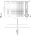
- FIG. 6 shows a structure of a slot of an NR frame, based on an embodiment of the present disclosure.
- the embodiment of FIG. 6 may be combined with various embodiments of the present disclosure.
- a slot includes a plurality of symbols in a time domain.
- one slot may include 14 symbols.
- one slot may include 12 symbols.
- one slot may include 7 symbols.
- one slot may include 6 symbols.
- a carrier includes a plurality of subcarriers in a frequency domain.
- a Resource Block (RB) may be defined as a plurality of consecutive subcarriers (e.g., 12 subcarriers) in the frequency domain.
- a Bandwidth Part (BWP) may be defined as a plurality of consecutive (Physical) Resource Blocks ((P)RBs) in the frequency domain, and the BWP may correspond to one numerology (e.g., SCS, CP length, and so on).
- a carrier may include a maximum of N number BWPs (e.g., 5 BWPs). Data communication may be performed via an activated BWP.
- Each element may be referred to as a Resource Element (RE) within a resource grid and one complex symbol may be mapped to each element.
- RE Resource Element
- a radio interface between a UE and another UE or a radio interface between the UE and a network may consist of an L1 layer, an L2 layer, and an L3 layer.
- the L1 layer may imply a physical layer.
- the L2 layer may imply at least one of a MAC layer, an RLC layer, a PDCP layer, and an SDAP layer.
- the L3 layer may imply an RRC layer.
- bandwidth part BWP
- carrier a bandwidth part (BWP) and a carrier
- the BWP may be a set of consecutive physical resource blocks (PRBs) in a given numerology.
- the PRB may be selected from consecutive sub-sets of common resource blocks (CRBs) for the given numerology on a given carrier.
- CRBs common resource blocks
- a reception bandwidth and transmission bandwidth of a UE are not necessarily as large as a bandwidth of a cell, and the reception bandwidth and transmission bandwidth of the BS may be adjusted.
- a network/BS may inform the UE of bandwidth adjustment.
- the UE receive information/configuration for bandwidth adjustment from the network/BS.
- the UE may perform bandwidth adjustment based on the received information/configuration.
- the bandwidth adjustment may include an increase/decrease of the bandwidth, a position change of the bandwidth, or a change in subcarrier spacing of the bandwidth.
- the bandwidth may be decreased during a period in which activity is low to save power.
- the position of the bandwidth may move in a frequency domain.
- the position of the bandwidth may move in the frequency domain to increase scheduling flexibility.
- the subcarrier spacing of the bandwidth may be changed.
- the subcarrier spacing of the bandwidth may be changed to allow a different service.
- a subset of a total cell bandwidth of a cell may be called a bandwidth part (BWP).
- the BA may be performed when the BS/network configures the BWP to the UE and the BS/network informs the UE of the BWP currently in an active state among the configured BWPs.
- the BWP may be at least any one of an active BWP, an initial BWP, and/or a default BWP.
- the UE may not monitor downlink radio link quality in a DL BWP other than an active DL BWP on a primary cell (PCell).
- the UE may not receive PDCCH, physical downlink shared channel (PDSCH), or channel state information - reference signal (CSI-RS) (excluding RRM) outside the active DL BWP.
- the UE may not trigger a channel state information (CSI) report for the inactive DL BWP.
- the UE may not transmit physical uplink control channel (PUCCH) or physical uplink shared channel (PUSCH) outside an active UL BWP.
- PUCCH physical uplink control channel
- PUSCH physical uplink shared channel
- the initial BWP may be given as a consecutive RB set for a remaining minimum system information (RMSI) control resource set (CORESET) (configured by physical broadcast channel (PBCH)).
- RMSI remaining minimum system information
- CORESET control resource set
- PBCH physical broadcast channel
- SIB system information block
- the default BWP may be configured by a higher layer.
- an initial value of the default BWP may be an initial DL BWP.
- DCI downlink control information
- the BWP may be defined for SL.
- the same SL BWP may be used in transmission and reception.
- a transmitting UE may transmit an SL channel or an SL signal on a specific BWP
- a receiving UE may receive the SL channel or the SL signal on the specific BWP.
- the SL BWP may be defined separately from a Uu BWP, and the SL BWP may have configuration signaling separate from the Uu BWP.
- the UE may receive a configuration for the SL BWP from the BS/network.
- the SL BWP may be (pre-)configured in a carrier with respect to an out-of-coverage NR V2X UE and an RRC_IDLE UE. For the UE in the RRC_CONNECTED mode, at least one SL BWP may be activated in the carrier.
- FIG. 7 shows an example of a BWP, based on an embodiment of the present disclosure.
- the embodiment of FIG. 7 may be combined with various embodiments of the present disclosure. It is assumed in the embodiment of FIG. 7 that the number of BWPs is 3.
- a common resource block may be a carrier resource block numbered from one end of a carrier band to the other end thereof.
- the PRB may be a resource block numbered within each BWP.
- a point A may indicate a common reference point for a resource block grid.
- the BWP may be configured by a point A, an offset N start BWP from the point A, and a bandwidth N size BWP .
- the point A may be an external reference point of a PRB of a carrier in which a subcarrier 0 of all numerologies (e.g., all numerologies supported by a network on that carrier) is aligned.
- the offset may be a PRB interval between a lowest subcarrier and the point A in a given numerology.
- the bandwidth may be the number of PRBs in the given numerology.
- V2X or SL communication will be described.
- FIG. 8 shows a radio protocol architecture for a SL communication, based on an embodiment of the present disclosure.
- the embodiment of FIG. 8 may be combined with various embodiments of the present disclosure. More specifically, FIG. 8(a) shows a user plane protocol stack, and FIG. 8(b) shows a control plane protocol stack.
- SLSS sidelink synchronization signal
- the SLSS may include a primary sidelink synchronization signal (PSSS) and a secondary sidelink synchronization signal (SSSS), as an SL-specific sequence.
- PSSS primary sidelink synchronization signal
- SSSS secondary sidelink synchronization signal
- the PSSS may be referred to as a sidelink primary synchronization signal (S-PSS)
- S-SSS sidelink secondary synchronization signal
- S-SSS sidelink secondary synchronization signal
- length-127 M-sequences may be used for the S-PSS
- length-127 gold sequences may be used for the S-SSS.
- a UE may use the S-PSS for initial signal detection and for synchronization acquisition.
- the UE may use the S-PSS and the S-SSS for acquisition of detailed synchronization and for detection of a synchronization signal ID.
- a physical sidelink broadcast channel may be a (broadcast) channel for transmitting default (system) information which must be first known by the UE before SL signal transmission/reception.
- the default information may be information related to SLSS, a duplex mode (DM), a time division duplex (TDD) uplink/downlink (UL/DL) configuration, information related to a resource pool, a type of an application related to the SLSS, a subframe offset, broadcast information, or the like.
- DM duplex mode
- TDD time division duplex
- UL/DL uplink/downlink
- a payload size of the PSBCH may be 56 bits including 24-bit CRC.
- the S-PSS, the S-SSS, and the PSBCH may be included in a block format (e.g., SL synchronization signal (SS)/PSBCH block, hereinafter, sidelink-synchronization signal block (S-SSB)) supporting periodical transmission.
- the S-SSB may have the same numerology (i.e., SCS and CP length) as a physical sidelink control channel (PSCCH)/physical sidelink shared channel (PSSCH) in a carrier, and a transmission bandwidth may exist within a (pre-)configured sidelink (SL) BWP.
- the S-SSB may have a bandwidth of 11 resource blocks (RBs).
- the PSBCH may exist across 11 RBs.
- a frequency position of the S-SSB may be (pre-)configured. Accordingly, the UE does not have to perform hypothesis detection at frequency to discover the S-SSB in the carrier.
- FIG. 9 shows a UE performing V2X or SL communication, based on an embodiment of the present disclosure.
- the embodiment of FIG. 9 may be combined with various embodiments of the present disclosure.
- the term 'UE' may generally imply a UE of a user.
- the BS may also be regarded as a sort of the UE.
- a UE 1 may be a first apparatus 100
- a UE 2 may be a second apparatus 200.
- the UE 1 may select a resource unit corresponding to a specific resource in a resource pool which implies a set of series of resources.
- the UE 1 may transmit an SL signal by using the resource unit.
- a resource pool in which the UE 1 is capable of transmitting a signal may be configured to the UE 2 which is a receiving UE, and the signal of the UE 1 may be detected in the resource pool.
- the BS may inform the UE 1 of the resource pool. Otherwise, if the UE 1 is out of the connectivity range of the BS, another UE may inform the UE 1 of the resource pool, or the UE 1 may use a pre-configured resource pool.
- the resource pool may be configured in unit of a plurality of resources, and each UE may select a unit of one or a plurality of resources to use it in SL signal transmission thereof.
- FIG. 10 shows a procedure of performing V2X or SL communication by a UE based on a transmission mode, based on an embodiment of the present disclosure.
- the transmission mode may be called a mode or a resource allocation mode.
- the transmission mode may be called an LTE transmission mode.
- the transmission mode may be called an NR resource allocation mode.
- FIG. 10(a) shows a UE operation related to an LTE transmission mode 1 or an LTE transmission mode 3.
- FIG. 10(a) shows a UE operation related to an NR resource allocation mode 1.
- the LTE transmission mode 1 may be applied to general SL communication
- the LTE transmission mode 3 may be applied to V2X communication.
- FIG. 10(b) shows a UE operation related to an LTE transmission mode 2 or an LTE transmission mode 4.
- FIG. 10(b) shows a UE operation related to an NR resource allocation mode 2.
- a BS may schedule an SL resource to be used by the UE for SL transmission.
- the BS may perform resource scheduling to a UE 1 through a PDCCH (more specifically, downlink control information (DCI)), and the UE 1may perform V2X or SL communication with respect to a UE 2 according to the resource scheduling.
- the UE 1 may transmit a sidelink control information (SCI) to the UE 2 through a physical sidelink control channel (PSCCH), and thereafter transmit data based on the SCI to the UE 2 through a physical sidelink shared channel (PSSCH).
- SCI sidelink control information
- PSCCH physical sidelink control channel
- PSSCH physical sidelink shared channel
- the UE may determine an SL transmission resource within an SL resource configured by a BS/network or a pre-configured SL resource.
- the configured SL resource or the pre-configured SL resource may be a resource pool.
- the UE may autonomously select or schedule a resource for SL transmission.
- the UE may perform SL communication by autonomously selecting a resource within a configured resource pool.
- the UE may autonomously select a resource within a selective window by performing a sensing and resource (re)selection procedure.
- the sensing may be performed in unit of subchannels.
- the UE 1 which has autonomously selected the resource within the resource pool may transmit the SCI to the UE 2 through a PSCCH, and thereafter may transmit data based on the SCI to the UE 2 through a PSSCH.
- FIG. 11 shows three cast types, based on an embodiment of the present disclosure.
- the embodiment of FIG. 11 may be combined with various embodiments of the present disclosure.
- FIG. 11(a) shows broadcast-type SL communication
- FIG. 11(b) shows unicast type-SL communication
- FIG. 11(c) shows groupcast-type SL communication.
- a UE may perform one-to-one communication with respect to another UE.
- the UE may perform SL communication with respect to one or more UEs in a group to which the UE belongs.
- SL groupcast communication may be replaced with SL multicast communication, SL one-to-many communication, or the like.
- HARQ hybrid automatic repeat request
- An error compensation scheme is used to secure communication reliability.
- Examples of the error compensation scheme may include a forward error correction (FEC) scheme and an automatic repeat request (ARQ) scheme.
- FEC forward error correction
- ARQ automatic repeat request
- the FEC scheme errors in a receiving end are corrected by attaching an extra error correction code to information bits.
- the FEC scheme has an advantage in that time delay is small and no information is additionally exchanged between a transmitting end and the receiving end but also has a disadvantage in that system efficiency deteriorates in a good channel environment.
- the ARQ scheme has an advantage in that transmission reliability can be increased but also has a disadvantage in that a time delay occurs and system efficiency deteriorates in a poor channel environment.
- a hybrid automatic repeat request (HARQ) scheme is a combination of the FEC scheme and the ARQ scheme.
- HARQ scheme it is determined whether an unrecoverable error is included in data received by a physical layer, and retransmission is requested upon detecting the error, thereby improving performance.
- HARQ feedback and HARQ combining in the physical layer may be supported.
- the receiving UE may receive the PSSCH from a transmitting UE, and the receiving UE may transmit HARQ feedback for the PSSCH to the transmitting UE by using a sidelink feedback control information (SFCI) format through a physical sidelink feedback channel (PSFCH).
- SFCI sidelink feedback control information
- PSFCH physical sidelink feedback channel
- the SL HARQ feedback may be enabled for unicast.
- a non-code block group non-CBG
- the receiving UE may generate HARQ-ACK.
- the receiving UE may transmit the HARQ-ACK to the transmitting UE.
- the receiving UE may transmit HARQ-NACK to the transmitting UE.
- the SL HARQ feedback may be enabled for groupcast.
- two HARQ feedback options may be supported for groupcast.
- all UEs performing groupcast communication may share a PSFCH resource.
- UEs belonging to the same group may transmit HARQ feedback by using the same PSFCH resource.
- each UE performing groupcast communication may use a different PSFCH resource for HARQ feedback transmission.
- UEs belonging to the same group may transmit HARQ feedback by using different PSFCH resources.
- the receiving UE may determine whether to transmit the HARQ feedback to the transmitting UE based on a transmission-reception (TX-RX) distance and/or RSRP.
- TX-RX transmission-reception
- the receiving UE may transmit HARQ feedback for the PSSCH to the transmitting UE. Otherwise, if the TX-RX distance is greater than the communication range requirement, the receiving UE may not transmit the HARQ feedback for the PSSCH to the transmitting UE.
- the transmitting UE may inform the receiving UE of a location of the transmitting UE through SCI related to the PSSCH.
- the SCI related to the PSSCH may be second SCI.
- the receiving UE may estimate or obtain the TX-RX distance based on a location of the receiving UE and the location of the transmitting UE. For example, the receiving UE may decode the SCI related to the PSSCH and thus may know the communication range requirement used in the PSSCH.
- a time (offset) between the PSFCH and the PSSCH may be configured or pre-configured.
- this may be indicated to a BS by an in-coverage UE which uses the PUCCH.
- the transmitting UE may transmit an indication to a serving BS of the transmitting UE in a form of scheduling request (SR)/buffer status report (BSR), not a form of HARQ ACK/NACK.
- SR scheduling request
- BSR buffer status report
- the BS may schedule an SL retransmission resource to the UE.
- a time (offset) between the PSFCH and the PSSCH may be configured or pre-configured.
- TDM between the PSCCH/PSSCH and the PSFCH may be allowed for a PSFCH format for SL in a slot.
- a sequence-based PSFCH format having a single symbol may be supported.
- the single symbol may not an AGC duration.
- the sequence-based PSFCH format may be applied to unicast and groupcast.
- a PSFCH resource may be configured periodically as N slot durations, or may be pre-configured.
- N may be configured as one or more values greater than or equal to 1.
- N may be 1, 2, or 4.
- HARQ feedback for transmission in a specific resource pool may be transmitted only through a PSFCH on the specific resource pool.
- the receiving UE may transmit HARQ feedback for the PSSCH to the transmitting UE in a slot #(N+A).
- the slot #(N+A) may include a PSFCH resource.
- A may be a smallest integer greater than or equal to K.
- K may be the number of logical slots. In this case, K may be the number of slots in a resource pool. Alternatively, for example, K may be the number of physical slots. In this case, K may be the number of slots inside or outside the resource pool.
- the receiving UE may determine a frequency domain and/or code domain of the PSFCH resource based on an implicit mechanism in a configured resource pool. For example, the receiving UE may determine the frequency domain and/or code domain of the PSFCH resource, based on at least one of a slot index related to PSCCH/PSSCH/PSFCH, a sub-channel related to PSCCH/PSSCH, and/or an identifier for identifying each receiving UE in a group for HARQ feedback based on the groupcast option 2. Additionally/alternatively, for example, the receiving UE may determine the frequency domain and/or code domain of the PSFCH resource, based on at least one of SL RSRP, SINR, L1 source ID, and/or location information.
- the UE may select any one of HARQ feedback transmission through the PSFCH and HARQ feedback reception through the PSFCH based on a priority rule.
- the priority rule may be based on at least priority indication of the related PSCCH/PSSCH.
- the UE may select specific HARQ feedback transmission based on the priority rule.
- the priority rule may be based on at least priority indication of the related PSCCH/PSSCH.
- a plurality of receiving UEs may share a PSFCH resource to transmit HARQ feedback.
- a plurality of receiving UEs e.g., each receiving UE in a group
- each of PSFCH resources may be mapped to a time domain resource, a frequency domain resource, and a code domain resource.
- resources through which a plurality of PSSCHs are transmitted may overlap.
- resources through which a plurality of PSSCHs are transmitted may completely or partially overlap each other on a frequency domain.
- resources through which a plurality of PSSCHs are transmitted may completely or partially overlap each other on a time domain.
- resources through which a plurality of PSSCHs are transmitted may completely or partially overlap each other on a code domain. If all or a part of resources for transmitting a plurality of PSSCHs overlap, PSFCH resources for each PSSCH may need to be distinguished.
- PSSCHs transmitted through different resources may correspond to different transmitting UEs and/or receiving UEs, and PSFCH transmissions corresponding thereto may also occur from different UEs.
- different transmitting UEs may transmit PSSCHs through different resources, and different transmitting UEs may receive PSFCHs corresponding to the PSSCHs from different UEs.
- transmit power of the PSFCHs may be different.
- a problem in which the UE cannot detect a specific PSFCH signal may occur due to a large difference in receive power at the PSFCH receiving end.
- the case in which a plurality of PSFCH resources are multiplexed in the code domain may mean a case in which a plurality of PSFCH resources overlapping in time and frequency resources are transmitted by using different codes.
- FIG. 12 shows a diagram for explaining a problem in that a UE cannot detect a specific PSFCH signal due to a large difference in receive power at a PSFCH receiving end, based on an embodiment of the present disclosure.
- the embodiment of FIG. 12 may be combined with various embodiments of the present disclosure.
- a PSFCH transmitted by a UE2 to a UE1 and a PSFCH transmitted by a UE4 to a UE3 are CDM, that is, if the PSFCH from the UE2 and the PSFCH from the UE4 are transmitted on overlapping time and frequency resources by using different codes, the UE3 cannot detect the PSFCH transmitted by the UE4 if receive power of the PSFCH transmitted by the UE2 is greater than receive power of the PSFCH transmitted by the UE4 by a certain level in terms of the UE3.
- FIG. 13 shows an example in which a plurality of PSFCHs are CDM, based on an embodiment of the present disclosure.
- the embodiment of FIG. 13 may be combined with various embodiments of the present disclosure.
- a PSFCH corresponding to a PSSCH transmitted from a UE1 to a UE2 and a PSFCH corresponding to a PSSCH transmitted from a UE3 to a UE4 may be CDM.
- IBE inter-band emission
- a PSFCH resource #1 and a PSFCH resource #2 are adjacent on a frequency domain, HARQ feedback received through the PSFCH resource #1 and HARQ feedback received through the PSFCH resource #2 by the UE may interfere with each other. Therefore, due to the above IBE problem, the UE may fail to receive HARQ feedback.
- PSFCH resources for PSSCHs transmitted in a plurality of slots may occur in the same slot.
- the UE receiving the PSSCH may omit transmission of the PSFCH. That is, it may be efficient for the UE to preferentially secure a PSFCH resource corresponding to a resource for a PSSCH transmitted in a slot close in time to a slot in which PSFCH resources exists.
- a plurality of receiving UE which has received a PSCCH may transmit HARQ feedback for the same PSSCH, respectively.
- FIG. 14 shows a procedure for a UE to transmit/receive a PSFCH, based on an embodiment of the present disclosure.
- the embodiment of FIG. 14 may be combined with various embodiments of the present disclosure.
- a transmitting UE may transmit a PSCCH and/or a PSSCH to a receiving UE.
- the transmitting UE may determine a PSFCH resource based on the PSCCH and/or the PSSCH.
- the receiving UE may determine the PSFCH resource based on the PSCCH and/or the PSSCH.
- the PSFCH resource may be related to subchannel(s) and a slot for the PSSCH.
- the transmitting UE and/or the receiving UE may determine the PSFCH resource based on various methods and/or procedures proposed below.
- the receiving UE may transmit a PSFCH (e.g., HARQ feedback) on the PSFCH resource.
- the transmitting UE may receive the PSFCH (e.g., HARQ feedback) on the PSFCH resource.
- the UE may perform a first grouping for a set of combinations of code domain resources and/or a set of resource blocks (RBs) in which PSFCH resources may exist.
- the set of combinations of code domain resources and/or the set of resource blocks (RBs) in which PSFCH resources may be referred to as a PSFCH resource set.
- the UE may receive information related to the PSFCH resource set from a base station.
- the PSFCH resource set may be physical resource(s).
- the PSFCH resource set may be logical resource(s). If the PSFCH resource set is logical resource(s), the UE may additionally map the logical resource(s) to physical resource(s).
- the PSFCH resource set may exist for each PSFCH format.
- the UE may perform the first grouping for each PSFCH format.
- the UE may perform the first grouping for each type of the PSFCH format.
- Each group by the first grouping may correspond to sub-channel(s) for PSSCH(s).
- a sub-channel may include one or more RBs.
- each of PSFCH groups by the first grouping may correspond to each of sub-channels that can be used for PSSCH transmission.
- the PSFCH group by the first grouping may be referred to as a first PSFCH resource, a first PSFCH group, or a first PSFCH resource group.
- FIG. 15 shows each of PSFCH groups by the first grouping corresponding to each of sub-channels that can be used for PSSCH transmission, based on an embodiment of the present disclosure.
- the embodiment of FIG. 15 may be combined with various embodiments of the present disclosure.
- the PSFCH group 1 and the PSFCH group 2 by the first grouping may correspond to one sub-channel, respectively.
- the PSFCH group 1 by the first grouping may correspond to a first sub-channel for PSSCH(s)
- the PSFCH group 2 by the first grouping may correspond to a second sub-channel for PSSCH(s).
- each of PSFCH groups by the first grouping corresponds to each of sub-channels that can be used for PSSCH transmission, even if a specific sub-channel shares/collides between a plurality of PSSCHs, it is possible to prevent PSFCH resources from colliding.
- PSSCH transmission consists of a plurality of sub-channels, PSFCH resources may be unnecessarily limited.
- each of PSFCH groups by the first grouping may correspond to each of sub-channel groups based on PSSCH allocation.
- a PSSCH consists of N sub-channels
- one PSFCH group may correspond to a bundle of the N sub-channels.
- N may be an integer of 2 or more.
- FIG. 16 shows one PSFCH group corresponding to a bundle of N sub-channels, based on an embodiment of the present disclosure.
- the embodiment of FIG. 16 may be combined with various embodiments of the present disclosure.
- a PSFCH group by the first grouping may correspond to two sub-channels.
- the PSFCH resource may be more efficiently used in terms of network resource utilization according to resource allocation for PSSCH(s).
- a method for preventing PSFCH resources from colliding may be additionally required.
- the UE may perform a second grouping for each of PSFCH groups by the first grouping.
- each of PSFCH groups by the second grouping (hereinafter, level 2-group) may correspond to each of PSSCH transmission slots.
- the PSFCH group by the second grouping may be referred to as a second PSFCH resource, a second PSFCH group, or a second PSFCH resource group.
- the HARQ-related set may be a set of slots related to PSCCHs and/or PSSCHs in which PSFCHs can be transmitted in the same slot.
- mapping between level 2-groups and slots may be performed in such a way that (RB) interval(s) between PSFCH resources or the selected/determined level 2-groups is maximized.
- FIG. 17 shows an example of the second grouping in the case of each of PSFCH groups by the first grouping corresponding to each of sub-channels, based on an embodiment of the present disclosure.
- the embodiment of FIG. 17 may be combined with various embodiments of the present disclosure.
- the PSFCH group 1 by the first grouping may be divided into the PSFCH group 1-1, the PSFCH group 1-2, and the PSFCH group 1-3 by the second grouping.
- PSFCH resource(s) related to the third slot in the HARQ-related set may be the PSFCH group 1-1
- PSFCH resource(s) related to the second slot in the HARQ-related set may be the PSFCH group 1-3
- PSFCH resource(s) related to the first slot in the HARQ-related set may be the PSFCH group 1-2.
- the UE may receive HARQ feedback related to the PSSCH #1 through the PSFCH group 1-2, and the UE may receive HARQ feedback related to the PSSCH #2 through the PSFCH group 1-3, and the UE may receive HARQ feedback related to the PSSCH #3 through the PSFCH group 1-1.
- FIG. 18 shows an example of the second grouping in the case of each of PSFCH groups by the first grouping corresponding to each of sub-channels, based on an embodiment of the present disclosure.
- the embodiment of FIG. 18 may be combined with various embodiments of the present disclosure.
- the PSFCH group 1 by the first grouping may be divided into the PSFCH group 1-1, the PSFCH group 1-2, and the PSFCH group 1-3 by the second grouping.
- PSFCH resource(s) related to the third slot in the HARQ-related set may be the PSFCH group 1-1
- PSFCH resource(s) related to the second slot in the HARQ-related set may be the PSFCH group 1-2
- PSFCH resource(s) related to the first slot in the HARQ-related set may be the PSFCH group 1-3.
- the UE may receive HARQ feedback related to the PSSCH #1 through the PSFCH group 1-3, and the UE may receive HARQ feedback related to the PSSCH #2 through the PSFCH group 1-2, and the UE may receive HARQ feedback related to the PSSCH #3 through the PSFCH group 1-1.
- FIG. 19 shows an example of the second grouping in the case of PSFCH groups by the first grouping corresponding to a plurality of sub-channels, based on an embodiment of the present disclosure.
- the embodiment of FIG. 19 may be combined with various embodiments of the present disclosure.
- UE(s) transmits the PSSCH #1 to the PSSCH #3 through one sub-channel and UE(s) transmits the PSSCH #4 to the PSSCH #6 through two sub-channels.
- the PSFCH group 1 related to the PSSCH #1 to the PSSCH #3 and the PSFCH group 2 related to the PSSCH #4 to the PSSCH #6 may overlap in time and frequency.
- the PSFCH group 1 by the first grouping may be divided into the PSFCH group 1-1, the PSFCH group 1-2, and the PSFCH group 1-3 by the second grouping
- the PSFCH group 2 by the first grouping may be divided into the PSFCH group 2-1, the PSFCH group 2-2, and the PSFCH group 2-3 by the second grouping.
- the PSFCH group 1-1 may be PSFCH resource(s) related to the PSSCH #3 of the slot #3, and the PSFCH group 1-2 may be PSFCH resource(s) related to the PSSCH #1 of the slot #1, and the PSFCH group 1-3 may be PSFCH resource(s) related to the PSSCH #2 of the slot #2.
- the PSFCH group 2-1 may be PSFCH resource(s) related to the PSSCH #6 in the slot #3, and the PSFCH group 2-2 may be PSFCH resource(s) related to the PSSCH #4 in the slot #1, and the PSFCH group 2-3 may be PSFCH resource(s) related to the PSSCH #5 in the slot #2.
- the UE(s) may receive HARQ feedback related to the PSSCH #1 through the PSFCH group 1-2, and the UE(s) may receive HARQ feedback related to the PSSCH #2 through the PSFCH group 1-3, and the UE(s) may receive HARQ feedback related to the PSSCH #3 through the PSFCH group 1-1.
- the UE(s) may receive HARQ feedback related to the PSSCH #4 through the PSFCH group 2-2, and the UE(s) may receive HARQ feedback related to the PSSCH #5 through the PSFCH group 2-3, and the UE(s) may receive HARQ feedback related to the PSSCH #6 through the PSFCH group 2-1.
- a plurality of PSSCHs transmitted by the UE(s) may overlap in (resource) regions partially or fully. Therefore, for example, if a UE receives HARQ feedback through the PSFCH group 1-1, the UE needs to distinguish/determine whether the HARQ feedback is HARQ feedback related to the PSSCH #3 or HARQ feedback related to the PSSCH #6. Alternatively, for example, if a UE receives HARQ feedback through the PSFCH group 1-2, the UE needs to distinguish/determine whether the HARQ feedback is HARQ feedback related to the PSSCH #1 or HARQ feedback related to the PSSCH #6.
- the above problem can be solved through a third grouping, which will be described later.
- the UE may omit HARQ feedback based on latency requirements of sidelink service(s).
- frequency domain interval(s) between PSFCH resources used actually may be maximized.
- the IBE problem can be alleviated. For example, if transmission of HARQ feedback for the PSSCH #1 is omitted in the embodiment of FIG. 17 , IBE between HARQ feedback received through the PSFCH group 1-1 and HARQ feedback received through the PSFCH group 1-3 by a UE may be minimized.
- a set of RBs for PSFCH resource(s) may be (pre-)configured for the UE differently for each resource pool, or may be (pre-)configured for the UE independently for each resource pool. That is, the UE may receive configuration information related to the set of RBs for PSFCH resource(s) corresponding to each of a plurality of resource pools, from a base station/network.
- the size of each of PSFCH groups by the first grouping may be the same.
- the size of each of PSFCH groups by the first grouping may be different from each other.
- the size of each of PSFCH groups by the second grouping may be the same.
- the size of each of PSFCH groups by the second grouping may be different from each other.
- the size of each of PSFCH groups by the first grouping may be the same.
- the size of each of PSFCH groups by the second grouping may be the same.
- the size of each of PSFCH groups by the second grouping may be set/determined by dividing the number of RBs included in the set of RBs for PSFCH resource(s) by a value which is obtained by multiplying the number of sub-channels in the resource pool by the value related to the period of PSFCH resource(s).
- the size of each of PSFCH groups by the second grouping may be set/determined based on Equation 1.
- the size of the PSFCH group by the second grouping may be the number of RBs included in the second PSFCH resource.
- the size of a PSFCH group by the second grouping The number of RBs included in a set of RBs for PSFCH resource s The number of subchannels in a resource pool ⁇ A value related to a period of PSFCH resource s
- the UE may maintain the size of each of PSFCH groups by the first grouping equally, and the UE may not use some RB(s) in the set of RBs for PSFCH resource(s).
- the RB(s) not used as PSFCH resource(s) may be RB(s) with high RB index(es) among RBs included in the set of RBs for PSFCH resource(s).
- the RB(s) not used as PSFCH resource(s) may be K RBs with high RB index(es) among RBs included in the set of RBs for PSFCH resource(s).
- K may be a positive integer.
- the RB(s) not used as PSFCH resource(s) may be RB(s) with low RB index(es) among RBs included in the set of RBs for PSFCH resource(s).
- the RB(s) not used as PSFCH resource(s) may be L RBs with low RB index(es) among RBs included in the set of RBs for PSFCH resource(s).
- L may be a positive integer.
- the size of each of PSFCH groups by the first grouping may be determined/set differently.
- the UE may maintain the size of each of PSFCH groups by the second grouping equally, and the UE may not use some RB(s) in the set of RBs for PSFCH resource(s).
- the RB(s) not used as PSFCH resource(s) may be distributed in each of PSFCH resource groups by the first grouping.
- the UE may not use one or more RBs with high RB index(es) among RBs in each of PSFCH resource groups by the first grouping as PSFCH resource(s).
- the UE may not use one or more RBs with low RB index(es) among RBs in each of PSFCH resource groups by the first grouping as PSFCH resource(s).
- the size of each of PSFCH groups by the second grouping may be determined/set differently.
- the size of each of PSFCH groups by the second grouping may be set/determined by rounding up a value which is obtained by dividing the number of RBs included in the set of RBs for PSFCH resource(s) by a value which is obtained by multiplying the number of sub-channels in the resource pool by the value related to the period of PSFCH resource(s).
- the size of each of PSFCH groups by the second grouping may be set/determined based on Equation 2.
- the size of a PSFCH group by the second grouping ⁇
- the number of RBs included in a set of RBs for PSFCH resource s The number of subchannels in a resource pool ⁇ A value related to a period of PSFCH resource s ⁇
- the size of each of PSFCH groups by the second grouping may be set/determined by rounding down a value which is obtained by dividing the number of RBs included in the set of RBs for PSFCH resource(s) by a value which is obtained by multiplying the number of sub-channels in the resource pool by the value related to the period of PSFCH resource(s).
- the size of each of PSFCH groups by the second grouping may be set/determined based on Equation 3.
- the size of a PSFCH group by the second grouping ⁇
- the number of RBs included in a set of RBs for PSFCH resource s The number of subchannels in a resource pool ⁇ A value related to a period of PSFCH resource s ⁇
- the UE may set/determine the size of each of PSFCH groups by the first grouping or the size of each of PSFCH groups by the second grouping to be the same as possible (i.e., so that the size difference of each of PSFCH groups is 1 or less).
- PSFCH groups having a relatively large size may belong to the same PSFCH group by the first grouping.
- a relatively large number of PSFCH candidate resources may be allocated to PSFCH group(s) corresponding to the first subchannel in a resource pool.
- PSFCH groups having a relatively large size may belong to different PSFCH groups by the first grouping.
- PSFCH groups having a relatively large size may be distributed to each of PSFCH groups by the first grouping.
- a relatively large number of PSFCH candidate resources may be allocated to PSFCH group(s) corresponding to fast slot(s) in a time domain.
- a relatively large number of PSFCH candidate resources may be allocated to PSFCH group(s) corresponding to late slot(s) in a time domain.
- the UE may perform a third grouping for each of PSFCH groups by the second grouping (i.e., level 2-groups).
- the PSFCH group by the third grouping may be referred to as a third PSFCH resource, a third PSFCH group, or a third PSFCH resource group. If PSFCH resources related to a plurality of PSSCHs overlap as in the embodiment of FIG. 19 , the UE may perform the third grouping in order to distinguish/determine a PSSCH to which HARQ feedback received on the same PSFCH resource is related.
- PSFCH groups by the third grouping may correspond to parameter(s) for discriminating PSSCHs sharing all or some sub-channels.
- the UE which transmits a PSSCH may perform the third grouping for a specific level 2-group, by using a demodulation reference signal (DMRS) sequence for the PSSCH and/or a PSCCH corresponding to the PSSCH or parameter(s) used to generate the DMRS sequence.
- the UE which transmits a PSSCH may perform the third grouping for a specific level 2-group, by using information on sub-channel(s) to which a PSCCH corresponding to the PSSCH is mapped.
- DMRS demodulation reference signal
- the UE which transmits a PSSCH may perform the third grouping for a specific level 2-group, by using resource allocation information for the PSSCH.
- the UE which transmits a PSSCH and/or a PSCCH may perform the third grouping for a specific level 2-group, by using all or a part of an L1-source ID transmitted/indicated through a SCI.
- the UE which transmits a PSSCH and/or a PSCCH may perform the third grouping for a specific level 2-group by using Equation 4.
- the value of X may be pre-defined for the UE.
- the value of X may be configured or pre-configured for the UE for each resource pool.
- the value of X may be configured or pre-configured for the UE for each PSFCH resource set.
- the operation configured for the UE may include the operation of a base station/network transmitting configuration related information to the UE.
- the parameter may be inferred/obtained from the demodulation reference signal (DMRS) sequence for the PSSCH and/or the PSCCH corresponding to the PSSCH or parameter(s) used to generate the DMRS sequence.
- DMRS demodulation reference signal
- PSCCHs transmitted by different UEs may collide in the same resource.
- receiving UE(s) may distinguish PSCCHs transmitted by different UEs in the same resource.
- the DMRS sequence or parameter(s) used to generate the DMRS sequence may be used to distinguish PSFCH resources associated with a plurality of PSSCHs sharing all or a part of resources.
- the parameter may be inferred/obtained from sub-channel(s) to which a PSCCH corresponding to the PSSCH is mapped. Even if a part of sub-channels overlaps between a plurality of PSSCH resources, PSCCH resources may be different from each other. Accordingly, based on sub-channel(s) to which the PSCCH corresponding to the PSSCH is mapped, collision between PSFCHs corresponding to PSSCHs in which all or a part of resources are shared can be prevented.
- the parameter may be inferred/obtained from resource allocation information for the PSSCH.
- the resource allocation information for the PSSCH may include a starting sub-channel and/or the number of sub-channels, etc.
- PSFCH resources corresponding to different PSSCHs may be distinguished.
- PSFCH resources corresponding to different PSSCHs may be distinguished.
- the number of resource allocation information for the PSSCH may be large according to a combination thereof. Therefore, it may be difficult for the UE to secure PSFCH resources.
- a specific PSFCH resource in the level 3-group may be inferred/obtained from information on a receiving UE and/or PSFCH transmission.
- a transmitting UE and/or a receiving UE may determine a specific PSFCH resource in the level 3-group based on the information on the receiving UE and/or PSFCH transmission.
- a plurality of receiving UEs which have received the same PSSCH from a transmitting UE may transmit HARQ feedback to the transmitting UE by using each of allocated PSFCH resources, respectively.
- the PSFCH resource may be divided based on at least information on a UE transmitting HARQ feedback (or a UE receiving the PSSCH).
- the information on the UE receiving the PSSCH may be information provided from a higher layer.
- the information provided from the higher layer may be identification information (e.g., ID, hereinafter, receiving UE identification information) assigned to each receiving UE in order to distinguish receiving UEs within the same group in the groupcast.
- the transmitting UE may infer/obtain the information on the UE receiving the PSSCH from a source ID of the UE receiving the PSSCH.
- the plurality of UEs may perform power control for PSFCHs.
- the difference in PSFCH receive power may not be large.
- the IBE problem and/or the Near-Far problem between PSFCH reception may be alleviated. Therefore, the performance degradation due to disposing PSFCH resources in adjacent RBs or performing CDM in the same RB may be insignificant.
- the receiving UE may select/determine an RB with an RB index (Y+M) mod Z in the third group as an RB for PSFCH transmission.
- M may be a value related to identification information allocated to the receiving UE
- Z may be a value of the number of RBs included in the third group.
- a receiving UE may change/determine a cyclic shift value used to generate each PSFCH sequence to/as an L1-source ID. Additionally/alternatively, for example, if a plurality of PSFCH resources related to each different receiving UE identification information in the same RB overlap each other, in order to distinguish them, a receiving UE may change/determine a cyclic shift value used to generate each PSFCH sequence to/as receiving UE identification information.
- the receiving UE may increase a cyclic shift index by a multiple of Z, by using a group identification information value.
- the receiving UE may increase a cyclic shift index according to the increased value of L1-source ID mod X.
- the final cyclic shift index changed/determined by the receiving UE may be expressed as a sum of a value of L1-source ID mod X and a rounded down value of the receiving UE identification information (M)/Z.
- the final cyclic shift index changed/determined by the receiving UE may be obtained based on Equation 5.
- the final cyclic shift index L 1 source ID mod X + ⁇ M Z ⁇
- the UE may perform the third grouping operation and/or the selection/determination operation of a PSFCH resource in the third group (or level 3-group) in units of RBs.
- the UE may perform the third grouping operation and/or the selection/determination operation of a PSFCH resource in the third group (or level 3-group) in units of a combination of RBs and cyclic shifts.
- the above form or operation method may be different based on at least one of the number of RBs corresponding to PSFCH resources constituting the second group (or level 2-group) and the total number of member IDs supportable in groupcast HARQ feedback mode 2 (pre-)configured for each resource pool, the number of member IDs per a subchannel allocated for one PSSCH, the number of cyclic shifts for CDM per a RB, the number of sub-channels in a resource pool, a period of PSFCH resources, and/or the size of the second group (or level 2-group).
- the UE may perform the third grouping operation and/or the selection/determination operation of a PSFCH resource in the third group (or level 3-group) in units of RBs. For example, if the number of RBs corresponding to the second group (or level 2-group) is greater than a value obtained by multiplying a value of X by the total number of UEs supportable in groupcast HARQ feedback mode 2 (pre-)configured for each resource pool, the UE may perform the third grouping operation and/or the selection/determination operation of a PSFCH resource in the third group (or level 3-group) in units of RBs.
- the UE may perform the third grouping operation and/or the selection/determination operation of a PSFCH resource in the third group (or level 3-group) in units of RBs.
- the UE may perform the third grouping operation and/or the selection/determination operation of a PSFCH resource in the third group (or level 3-group) in units of a combination of RBs and cyclic shifts.
- a cyclic shift may be set to a specific value, and a value of an RB may be derived/determined from a value of L1-source ID mod X and/or a group identification information value.
- a value of a cyclic shift and a value of an RB may be derived/determined from a value of L1-source ID mod X and/or group identification information.
- the RB index may increase from the starting RB value derived by the value of L1-source ID mod X.
- the RB index may return to the starting RB value derived by the value of L1-source ID mod X again.
- the value of the cyclic shift or the index of the cyclic shift may increase.
- the above method for allocating/selecting/determining PSFCH resource(s) is only an embodiment, and some grouping steps may be omitted or group selection/determination process(es) based on specific parameter(s) may be omitted. Also, the order of the grouping steps may be different. Specifically, for example, a method of preventing collision between PSFCHs corresponding to PSSCHs and a method of distinguishing receiving UEs in groupcast may be processed in the same step.
- the transmitting UE and/or the receiving UE may perform the first grouping and the second grouping, and the transmitting UE and/or the receiving UE may select/determine a PSFCH resource in the level 2-group based on pairing information between the receiving UE and the transmitting UE for the PSSCH.
- the pairing information may include a source ID and/or a destination ID.
- the transmitting UE which transmits the PSSCH may select/determine the PSFCH resource in the level 2-group based on a destination ID and a source ID of the transmitting UE.
- the receiving UE which receives the PSSCH may select/determine the PSFCH resource in the level 2-group based on a destination ID and a source ID of the transmitting UE.
- the pairing information may include a source ID and/or identifier information of a group.
- the transmitting UE which transmits the PSSCH may select/determine the PSFCH resource in the level 2-group based on a source ID of the transmitting UE and identifier information of the group in which the groupcast is performed.
- the receiving UE which receives the PSSCH may select/determine the PSFCH resource in the level 2-group based on a source ID of the transmitting UE and identifier information of the group in which the groupcast is performed.
- the transmitting UE and/or the receiving UE may select/determine the level 3-group based on information related to the receiving UE for the PSSCH, and the transmitting UE and/or the receiving UE may select/determine the PSFCH resource in the level 3-group based on at least one of information related to the transmitting UE for the PSSCH, DMRS sequence information for the PSCCH, and/or DMRS sequence information for the PSSCH.
- the number of group steps for the PSFCH resource, a type of parameter(s) referenced for each group step, and/or a combination thereof, etc. may be configured or pre-configured for the UE for each resource pool.
- the size of the physical resources for PSFCHs may be smaller than the size of the logical resources in terms of a frequency domain, a time domain, and/or a code domain. If the size of the physical resources is smaller than the size of the logical resources, some PSFCH resources may overlap each other.
- the mapping process to the physical resources may be performed in units of all logical resources or may be performed for a group of a specific level. For example, in the case of the level 1-group and the level 2-group, it may not be allowed to overlap PSFCH resources between groups. In the case of the level 3-group, it may be allowed to overlap some PSFCH resources in a frequency domain, a time domain, and/or a code domain depending on the size of the physical resources.
- the transmitting UE may select/determine a set of RBs corresponding to a set of sub-channels according to PSSCH resource allocation as the level 1-group for the PSFCH. Additionally, the transmitting UE may select/determine the level 2-group based on the slot in which the PSSCH is transmitted in the selected/determined level 1-group. Additionally, the transmitting UE may select/determine the level 3-group in the selected level 2-group, based on transmission information on the PSSCH (e.g., a DMRS sequence or a source ID of the transmitting UE).
- transmission information on the PSSCH e.g., a DMRS sequence or a source ID of the transmitting UE.
- the transmitting UE may select/determine a specific PSFCH resource in the level 3-group. If the PSFCH resource is divided between each of PSSCH receiving UEs in groupcast, the transmitting UE may receive HARQ feedback from PSSCH receiving UE(s) through PSFCH resource(s) that can be used in the level 3-group.
- the receiving UE may perform the group selection/determination in the same process to the level 3-group selection/determination as the transmitting UE.
- the receiving UE may select/determine a specific PSFCH resource in the level 3-group based on the same criteria as in the transmitting UE. If the PSFCH resource is divided between each of PSSCH receiving UEs in groupcast, each of receiving UEs may select/determine a PSFCH resource based on information related to a receiving UE (e.g., an identifier provided by a higher layer or a source ID of the receiving UE).
- the receiving UE may transmit HARQ feedback to the PSSCH transmitting UE by using the selected/determined PSFCH resource.
- the number and combination of sub-channels allocated for PSSCHs for each slot may be different.
- UE(s) may transmit a PSSCH through a sub-channel #1 to a sub-channel #6 in the first slot, and UE(s) may transmit a PSSCH through a sub-channel #4 to a sub-channel #9 in the second slot.
- a parameter combination and/or an applied order may be required for PSFCH resource allocation/selection/determination differently.
- the UE may allocate PSFCH resources corresponding to different slots in the HARQ-related set in the same sub-channel. According to this method, even if the sub-channel combinations allocated for the PSSCH for each slot are different, the collision between the PSFCH resource sets can be efficiently managed/avoided.
- the PSSCH transmitting UE may select/determine the level 1-group based on sub-channel(s) allocated for the PSSCH, and the PSSCH transmitting UE may select/determine the second group based on information related to the PSSCH transmitting UE (or information related to the receiving UE).
- the PSSCH transmitting UE may select/determine the third group based on slot information for the PSSCH, and the PSSCH transmitting UE may select/determine the final PSFCH resource based on information related to the PSSCH receiving UE (or information related to the transmitting UE).
- the PSSCH transmitting UE may select/determine the level 1-group based on sub-channel(s) allocated for the PSSCH, and the PSSCH transmitting UE may select/determine the second group based on information related to the PSSCH transmitting UE (or information related to the receiving UE).
- the PSSCH transmitting UE may select/determine the third group based on information related to the PSSCH receiving UE (or information related to the transmitting UE), and the PSSCH transmitting UE may select/determine the final PSFCH resource based on slot information for the PSSCH.
- the UE may reserve PSFCH resources for a plurality of sub-channels. Otherwise, for a specific PSSCH transmission, the UE may reserve PSFCH resources only in a specific sub-channel.
- the UE(s) and/or the base station may group/manage PSFCH resources. Accordingly, an effect of efficiently supporting the HARQ operation may occur.
- FIG. 20 shows a method for a first device to determine a resource for receiving HARQ feedback, based on an embodiment of the present disclosure.
- the embodiment of FIG. 20 may be combined with various embodiments of the present disclosure.
- the first device 100 may transmit a PSSCH to the second device 200.
- the first device 100 may determine a resource for a PSFCH.
- the resource for the PSFCH may be determined based on at least one of the first grouping, the second grouping, or the third grouping.
- the first device 100 may determine the resource for the PSFCH based on various embodiments proposed in the present disclosure.
- the first device 100 may receive HARQ feedback from the second device 200 through the PSFCH related to the PSSCH. The order of the above steps may be changed.
- FIG. 21 shows a method for a second device to determine a resource for transmitting HARQ feedback, based on an embodiment of the present disclosure.
- the embodiment of FIG. 21 may be combined with various embodiments of the present disclosure.
- the second device 200 may receive a PSSCH from the first device 100.
- the second device 200 may determine a resource for a PSFCH.
- the resource for the PSFCH may be determined based on at least one of the first grouping, the second grouping, or the third grouping.
- the second device 200 may determine the resource for the PSFCH based on various embodiments proposed in the present disclosure.
- the second device 200 may transmit HARQ feedback to the first device 100 through the PSFCH related to the PSSCH. The order of the above steps may be changed.
- FIG. 22 shows a method for a first device to perform wireless communication, based on an embodiment of the present disclosure.
- the embodiment of FIG. 22 may be combined with various embodiments of the present disclosure.
- the first device may receive, from a second device, a physical sidelink shared channel (PSSCH).
- the first device may determine a physical sidelink feedback channel (PSFCH) resource related to the PSSCH.
- the first device may transmit, to the second device, hybrid automatic repeat request (HARQ) feedback based on the PSFCH resource.
- HARQ hybrid automatic repeat request
- at least one subchannel for the PSSCH may be related to at least one first PSFCH resource including at least one second PSFCH resource
- each second PSFCH resource included in the at least one first PSFCH resource may be related to each slot on the at least one subchannel.
- the PSFCH resource may be determined based on information related to the at least one subchannel for the PSSCH, information related to at least one slot for the PSSCH, and a source ID of the second device.
- the first device may determine one or more PRBs for PSFCH transmission corresponding to the PSSCH received on the i-th slot and the j-th subchannel.
- a UE is provided by rbSetPSFCH a set of M PRB , set PSFCH PRBs in a resource pool for PSFCH transmission in a PRB of the resource pool.
- the UE expects that M PRB , set PSFCH is
- the first device may determine the number of available PSFCH resources.
- the PSFCH resources are first indexed according to an ascending order of the PRB index, from the N type PSFCH ⁇ M
- the first device may determine an index of the PSFCH resource based on Table 7. In addition, the first device may transmit HARQ feedback on the PSFCH resource corresponding to the index. Additionally, if the index is related to a specific cyclic shift, the first device may transmit HARQ feedback to which the specific cyclic shift is applied, based on the PSFCH resource corresponding to the index.
- a UE determines an index of a PSFCH resource for a PSFCH transmission in response to a PSSCH reception, aa R PRB ,CS PSFCH P ID + M ID modR PRB , CS PSFCH where P ID is a physical layer source ID provided by SCI format 0_2 scheduling the PSSCH reception, M ID is zero or M ID is the identity of the UE receiving the PSSCH as indicated by higher layers.
- each subchannel for the PSSCH may be related to each first PSFCH resource including the at least one second PSFCH resource.
- a plurality of subchannels for the PSSCH may be related to one first PSFCH resource among the at least one first PSFCH resource including the at least one second PSFCH resource.
- a size of the second PSFCH resource may be a value which is obtained by dividing a number of resource blocks (RBs) included in a set of PSFCH resources by a value which is obtained by multiplying a number of subchannels in a resource pool by a period of the PSFCH resource.
- the size of the second PSFCH resource may be a number of RBs included in the second PSFCH resource.
- the period of the PSFCH resource may be a number of PSSCH slots related to a slot including the PSFCH resource.
- the PSFCH resource may be one RB, determined based on the source ID of the second device, among at least one second PSFCH resource related to the at least one subchannel and the at least one slot for the PSSCH.
- the PSFCH resource may be determined based on the information related to the at least one subchannel for the PSSCH, the information related to the at least one slot for the PSSCH, the source ID of the second device, and an ID of the first device.
- the ID of the first device may be an ID for identifying the first device within a group related to groupcast communication.
- the first device may determine information related to a cyclic shift applied to the HARQ feedback on the PSFCH resource.
- the information related to the cyclic shift applied to the HARQ feedback on the PSFCH resource may be determined based on the information related to the at least one subchannel for the PSSCH, the information related to the at least one slot for the PSSCH, and the source ID of the second device.
- the information related to the cyclic shift applied to the HARQ feedback on the PSFCH resource may be determined based on the information related to the at least one subchannel for the PSSCH, the information related to the at least one slot for the PSSCH, the source ID of the second device, and an ID of the first device.
- the ID of the first device may be an ID for identifying the first device within a group related to groupcast communication.
- the HARQ feedback may be transmitted to the second device on the PSFCH resource based on the information related to the cyclic shift.
- the processor 102 of the first device 100 may control the transceiver 106 to receive, from a second device, a physical sidelink shared channel (PSSCH).
- the processor 102 of the first device 100 may determine a physical sidelink feedback channel (PSFCH) resource related to the PSSCH.
- the processor 102 of the first device 100 may control the transceiver 106 to transmit, to the second device, hybrid automatic repeat request (HARQ) feedback based on the PSFCH resource.
- PSSCH physical sidelink shared channel
- HARQ hybrid automatic repeat request
- At least one subchannel for the PSSCH may be related to at least one first PSFCH resource including at least one second PSFCH resource, and each second PSFCH resource included in the at least one first PSFCH resource may be related to each slot on the at least one subchannel.
- the PSFCH resource may be determined based on information related to the at least one subchannel for the PSSCH, information related to at least one slot for the PSSCH, and a source ID of the second device.
- a first device configured to perform wireless communication may comprise: one or more memories storing instructions; one or more transceivers; and one or more processors connected to the one or more memories and the one or more transceivers.
- the one or more processors may execute the instructions to: receive, from a second device, a physical sidelink shared channel (PSSCH); determine a physical sidelink feedback channel (PSFCH) resource related to the PSSCH; and transmit, to the second device, hybrid automatic repeat request (HARQ) feedback based on the PSFCH resource.
- PSSCH physical sidelink shared channel
- PSFCH physical sidelink feedback channel
- HARQ hybrid automatic repeat request
- At least one subchannel for the PSSCH may be related to at least one first PSFCH resource including at least one second PSFCH resource, and each second PSFCH resource included in the at least one first PSFCH resource may be related to each slot on the at least one subchannel.
- the PSFCH resource may be determined based on information related to the at least one subchannel for the PSSCH, information related to at least one slot for the PSSCH, and a source ID of the second device.
- an apparatus configured to control a first user equipment (UE) performing wireless communication may be provided.
- the apparatus may comprise: one or more processors; and one or more memories operably connected to the one or more processors and storing instructions.
- the one or more processors may execute the instructions to: receive, from a second UE, a physical sidelink shared channel (PSSCH); determine a physical sidelink feedback channel (PSFCH) resource related to the PSSCH; and transmit, to the second UE, hybrid automatic repeat request (HARQ) feedback based on the PSFCH resource.
- PSSCH physical sidelink shared channel
- PSFCH physical sidelink feedback channel
- HARQ hybrid automatic repeat request
- At least one subchannel for the PSSCH may be related to at least one first PSFCH resource including at least one second PSFCH resource, and each second PSFCH resource included in the at least one first PSFCH resource may be related to each slot on the at least one subchannel.
- the PSFCH resource may be determined based on information related to the at least one subchannel for the PSSCH, information related to at least one slot for the PSSCH, and a source ID of the second UE.
- a non-transitory computer-readable storage medium storing instructions may be provided.
- the instructions when executed, may cause a first device to: receive, from a second device, a physical sidelink shared channel (PSSCH); determine a physical sidelink feedback channel (PSFCH) resource related to the PSSCH; and transmit, to the second device, hybrid automatic repeat request (HARQ) feedback based on the PSFCH resource.
- PSSCH physical sidelink shared channel
- PSFCH physical sidelink feedback channel
- HARQ hybrid automatic repeat request
- at least one subchannel for the PSSCH may be related to at least one first PSFCH resource including at least one second PSFCH resource, and each second PSFCH resource included in the at least one first PSFCH resource may be related to each slot on the at least one subchannel.
- the PSFCH resource may be determined based on information related to the at least one subchannel for the PSSCH, information related to at least one slot for the PSSCH, and a source ID of the second device.
- FIG. 23 shows a method for a second device to perform wireless communication, based on an embodiment of the present disclosure.
- the embodiment of FIG. 23 may be combined with various embodiments of the present disclosure.
- the second device may transmit, to a first device, a physical sidelink shared channel (PSSCH).
- the second device may determine a physical sidelink feedback channel (PSFCH) resource related to the PSSCH.
- the second device may receive, from the first device, a hybrid automatic repeat request (HARQ) feedback based on the PSFCH resource.
- HARQ hybrid automatic repeat request
- at least one subchannel for the PSSCH may be related to at least one first PSFCH resource including at least one second PSFCH resource
- each second PSFCH resource included in the at least one first PSFCH resource may be related to each slot on the at least one subchannel.
- the PSFCH resource may be determined based on information related to the at least one subchannel for the PSSCH, information related to at least one slot for the PSSCH, and a source ID of the second device.
- each subchannel for the PSSCH may be related to each first PSFCH resource including the at least one second PSFCH resource.
- a plurality of subchannels for the PSSCH may be related to one first PSFCH resource among the at least one first PSFCH resource including the at least one second PSFCH resource.
- a size of the second PSFCH resource may be a value which is obtained by dividing a number of resource blocks (RBs) included in a set of PSFCH resources by a value which is obtained by multiplying a number of subchannels in a resource pool by a period of the PSFCH resource.
- the second device may determine one or more PRBs for PSFCH reception corresponding to the PSSCH transmitted on the i-th slot and the j-th subchannel.
- the second device may determine the number of available PSFCH resources.
- the second device may determine an index of the PSFCH resource based on Table 7.
- the second device may receive HARQ feedback on the PSFCH resource corresponding to the index. Additionally, if the index is related to a specific cyclic shift, the second device may receive HARQ feedback to which the specific cyclic shift is applied, based on the PSFCH resource corresponding to the index.
- the processor 202 of the second device 200 may control the transceiver 206 to transmit, to a first device, a physical sidelink shared channel (PSSCH).
- the processor 202 of the second device 200 may determine a physical sidelink feedback channel (PSFCH) resource related to the PSSCH.
- the processor 202 of the second device 200 may control the transceiver 206 to receive, from the first device, a hybrid automatic repeat request (HARQ) feedback based on the PSFCH resource.
- HARQ hybrid automatic repeat request
- At least one subchannel for the PSSCH may be related to at least one first PSFCH resource including at least one second PSFCH resource, and each second PSFCH resource included in the at least one first PSFCH resource may be related to each slot on the at least one subchannel.
- the PSFCH resource may be determined based on information related to the at least one subchannel for the PSSCH, information related to at least one slot for the PSSCH, and a source ID of the second device.
- a second device configured to perform wireless communication
- the second device may comprise: one or more memories storing instructions; one or more transceivers; and one or more processors connected to the one or more memories and the one or more transceivers.
- the one or more processors may execute the instructions to: transmit, to a first device, a physical sidelink shared channel (PSSCH); determine a physical sidelink feedback channel (PSFCH) resource related to the PSSCH; and receive, from the first device, a hybrid automatic repeat request (HARQ) feedback based on the PSFCH resource.
- PSSCH physical sidelink shared channel
- PSFCH physical sidelink feedback channel
- HARQ hybrid automatic repeat request
- At least one subchannel for the PSSCH may be related to at least one first PSFCH resource including at least one second PSFCH resource, and each second PSFCH resource included in the at least one first PSFCH resource may be related to each slot on the at least one subchannel.
- the PSFCH resource may be determined based on information related to the at least one subchannel for the PSSCH, information related to at least one slot for the PSSCH, and a source ID of the second device.
- an apparatus configured to control a second user equipment (UE) performing wireless communication may be provided.
- the apparatus may comprise: one or more processors; and one or more memories operably connected to the one or more processors and storing instructions.
- the one or more processors may execute the instructions to: transmit, to a first UE, a physical sidelink shared channel (PSSCH); determine a physical sidelink feedback channel (PSFCH) resource related to the PSSCH; and receive, from the first UE, a hybrid automatic repeat request (HARQ) feedback based on the PSFCH resource.
- PSSCH physical sidelink shared channel
- PSFCH physical sidelink feedback channel
- HARQ hybrid automatic repeat request
- At least one subchannel for the PSSCH may be related to at least one first PSFCH resource including at least one second PSFCH resource, and each second PSFCH resource included in the at least one first PSFCH resource may be related to each slot on the at least one subchannel.
- the PSFCH resource may be determined based on information related to the at least one subchannel for the PSSCH, information related to at least one slot for the PSSCH, and a source ID of the second UE.
- a non-transitory computer-readable storage medium storing instructions may be provided.
- the instructions when executed, may cause a second device to: transmit, to a first device, a physical sidelink shared channel (PSSCH); determine a physical sidelink feedback channel (PSFCH) resource related to the PSSCH; and receive, from the first device, a hybrid automatic repeat request (HARQ) feedback based on the PSFCH resource.
- PSSCH physical sidelink shared channel
- PSFCH physical sidelink feedback channel
- HARQ hybrid automatic repeat request
- at least one subchannel for the PSSCH may be related to at least one first PSFCH resource including at least one second PSFCH resource, and each second PSFCH resource included in the at least one first PSFCH resource may be related to each slot on the at least one subchannel.
- the PSFCH resource may be determined based on information related to the at least one subchannel for the PSSCH, information related to at least one slot for the PSSCH, and a source ID of the second device.
- FIG. 24 shows a communication system 1, based on an embodiment of the present disclosure.
- a communication system 1 to which various embodiments of the present disclosure are applied includes wireless devices, Base Stations (BSs), and a network.
- the wireless devices represent devices performing communication using Radio Access Technology (RAT) (e.g., 5G New RAT (NR)) or Long-Term Evolution (LTE)) and may be referred to as communication/radio/SG devices.
- RAT Radio Access Technology
- the wireless devices may include, without being limited to, a robot 100a, vehicles 100b-1 and 100b-2, an extended Reality (XR) device 100c, a hand-held device 100d, a home appliance 100e, an Internet of Things (IoT) device 100f, and an Artificial Intelligence (AI) device/server 400.
- RAT Radio Access Technology
- NR 5G New RAT
- LTE Long-Term Evolution
- the wireless devices may include, without being limited to, a robot 100a, vehicles 100b-1 and 100b-2, an extended Reality (XR) device 100c, a hand-held device 100d, a home appliance 100
- the vehicles may include a vehicle having a wireless communication function, an autonomous vehicle, and a vehicle capable of performing communication between vehicles.
- the vehicles may include an Unmanned Aerial Vehicle (UAV) (e.g., a drone).
- UAV Unmanned Aerial Vehicle
- the XR device may include an Augmented Reality (AR)/Virtual Reality (VR)/Mixed Reality (MR) device and may be implemented in the form of a Head-Mounted Device (HMD), a Head-Up Display (HUD) mounted in a vehicle, a television, a smartphone, a computer, a wearable device, a home appliance device, a digital signage, a vehicle, a robot, etc.
- the hand-held device may include a smartphone, a smartpad, a wearable device (e.g., a smartwatch or a smartglasses), and a computer (e.g., a notebook).
- the home appliance may include a TV, a refrigerator, and a washing machine.
- the IoT device may include a sensor and a smartmeter.
- the BSs and the network may be implemented as wireless devices and a specific wireless device 200a may operate as a BS/network node with respect to other wireless devices.
- the wireless devices 100a to 100f may be connected to the network 300 via the BSs 200.
- An AI technology may be applied to the wireless devices 100a to 100f and the wireless devices 100a to 100f may be connected to the AI server 400 via the network 300.
- the network 300 may be configured using a 3G network, a 4G (e.g., LTE) network, or a 5G (e.g., NR) network.
- the wireless devices 100a to 100f may communicate with each other through the BSs 200/network 300, the wireless devices 100a to 100f may perform direct communication (e.g., sidelink communication) with each other without passing through the BSs/network.
- the vehicles 100b-1 and 100b-2 may perform direct communication (e.g.
- V2V Vehicle-to-Vehicle
- V2X Vehicle-to-everything
- Wireless communication/connections 150a, 150b, or 150c may be established between the wireless devices 100a to 100fBS 200, or BS 200BS 200.
- the wireless communication/connections may be established through various RATs (e.g., 5G NR) such as uplink/downlink communication 150a, sidelink communication 150b (or, D2D communication), or inter BS communication (e.g., relay, Integrated Access Backhaul (IAB)).
- the wireless devices and the BSs/the wireless devices may transmit/receive radio signals to/from each other through the wireless communication/connections 150a and 150b.
- the wireless communication/connections 150a and 150b may transmit/receive signals through various physical channels.
- various configuration information configuring processes various signal processing processes (e.g., channel encoding/decoding, modulation/demodulation, and resource mapping/demapping), and resource allocating processes, for transmitting/receiving radio signals, may be performed based on the various proposals of the present disclosure.
- various signal processing processes e.g., channel encoding/decoding, modulation/demodulation, and resource mapping/demapping
- resource allocating processes for transmitting/receiving radio signals
- FIG. 25 shows wireless devices, based on an embodiment of the present disclosure.
- a first wireless device 100 and a second wireless device 200 may transmit radio signals through a variety of RATs (e.g., LTE and NR).
- ⁇ the first wireless device 100 and the second wireless device 200 ⁇ may correspond to ⁇ the wireless device 100x and the BS 200 ⁇ and/or ⁇ the wireless device 100x and the wireless device 100x ⁇ of FIG. 24 .
- the first wireless device 100 may include one or more processors 102 and one or more memories 104 and additionally further include one or more transceivers 106 and/or one or more antennas 108.
- the processor(s) 102 may control the memory(s) 104 and/or the transceiver(s) 106 and may be configured to implement the descriptions, functions, procedures, proposals, methods, and/or operational flowcharts disclosed in this document.
- the processor(s) 102 may process information within the memory(s) 104 to generate first information/signals and then transmit radio signals including the first information/signals through the transceiver(s) 106.
- the processor(s) 102 may receive radio signals including second information/signals through the transceiver 106 and then store information obtained by processing the second information/signals in the memory(s) 104.
- the memory(s) 104 may be connected to the processor(s) 102 and may store a variety of information related to operations of the processor(s) 102.
- the memory(s) 104 may store software code including commands for performing a part or the entirety of processes controlled by the processor(s) 102 or for performing the descriptions, functions, procedures, proposals, methods, and/or operational flowcharts disclosed in this document.
- the processor(s) 102 and the memory(s) 104 may be a part of a communication modem/circuit/chip designed to implement RAT (e.g., LTE or NR).
- the transceiver(s) 106 may be connected to the processor(s) 102 and transmit and/or receive radio signals through one or more antennas 108.
- Each of the transceiver(s) 106 may include a transmitter and/or a receiver.
- the transceiver(s) 106 may be interchangeably used with Radio Frequency (RF) unit(s).
- the wireless device may represent a communication modem/circuit/chip.
- the second wireless device 200 may include one or more processors 202 and one or more memories 204 and additionally further include one or more transceivers 206 and/or one or more antennas 208.
- the processor(s) 202 may control the memory(s) 204 and/or the transceiver(s) 206 and may be configured to implement the descriptions, functions, procedures, proposals, methods, and/or operational flowcharts disclosed in this document.
- the processor(s) 202 may process information within the memory(s) 204 to generate third information/signals and then transmit radio signals including the third information/signals through the transceiver(s) 206.
- the processor(s) 202 may receive radio signals including fourth information/signals through the transceiver(s) 106 and then store information obtained by processing the fourth information/signals in the memory(s) 204.
- the memory(s) 204 may be connected to the processor(s) 202 and may store a variety of information related to operations of the processor(s) 202.
- the memory(s) 204 may store software code including commands for performing a part or the entirety of processes controlled by the processor(s) 202 or for performing the descriptions, functions, procedures, proposals, methods, and/or operational flowcharts disclosed in this document.
- the processor(s) 202 and the memory(s) 204 may be a part of a communication modem/circuit/chip designed to implement RAT (e.g., LTE or NR).
- the transceiver(s) 206 may be connected to the processor(s) 202 and transmit and/or receive radio signals through one or more antennas 208.
- Each of the transceiver(s) 206 may include a transmitter and/or a receiver.
- the transceiver(s) 206 may be interchangeably used with RF unit(s).
- the wireless device may represent a communication modem/circuit/chip.
- One or more protocol layers may be implemented by, without being limited to, one or more processors 102 and 202.
- the one or more processors 102 and 202 may implement one or more layers (e.g., functional layers such as PHY, MAC, RLC, PDCP, RRC, and SDAP).
- the one or more processors 102 and 202 may generate one or more Protocol Data Units (PDUs) and/or one or more Service Data Unit (SDUs) according to the descriptions, functions, procedures, proposals, methods, and/or operational flowcharts disclosed in this document.
- PDUs Protocol Data Units
- SDUs Service Data Unit
- the one or more processors 102 and 202 may generate messages, control information, data, or information according to the descriptions, functions, procedures, proposals, methods, and/or operational flowcharts disclosed in this document.
- the one or more processors 102 and 202 may generate signals (e.g., baseband signals) including PDUs, SDUs, messages, control information, data, or information according to the descriptions, functions, procedures, proposals, methods, and/or operational flowcharts disclosed in this document and provide the generated signals to the one or more transceivers 106 and 206.
- the one or more processors 102 and 202 may receive the signals (e.g., baseband signals) from the one or more transceivers 106 and 206 and acquire the PDUs, SDUs, messages, control information, data, or information according to the descriptions, functions, procedures, proposals, methods, and/or operational flowcharts disclosed in this document.
- signals e.g., baseband signals
- the one or more processors 102 and 202 may be referred to as controllers, microcontrollers, microprocessors, or microcomputers.
- the one or more processors 102 and 202 may be implemented by hardware, firmware, software, or a combination thereof.
- ASICs Application Specific Integrated Circuits
- DSPs Digital Signal Processors
- DSPDs Digital Signal Processing Devices
- PLDs Programmable Logic Devices
- FPGAs Field Programmable Gate Arrays
- the descriptions, functions, procedures, proposals, methods, and/or operational flowcharts disclosed in this document may be implemented using firmware or software and the firmware or software may be configured to include the modules, procedures, or functions.
- Firmware or software configured to perform the descriptions, functions, procedures, proposals, methods, and/or operational flowcharts disclosed in this document may be included in the one or more processors 102 and 202 or stored in the one or more memories 104 and 204 so as to be driven by the one or more processors 102 and 202.
- the descriptions, functions, procedures, proposals, methods, and/or operational flowcharts disclosed in this document may be implemented using firmware or software in the form of code, commands, and/or a set of commands.
- the one or more memories 104 and 204 may be connected to the one or more processors 102 and 202 and store various types of data, signals, messages, information, programs, code, instructions, and/or commands.
- the one or more memories 104 and 204 may be configured by Read-Only Memories (ROMs), Random Access Memories (RAMs), Electrically Erasable Programmable Read-Only Memories (EPROMs), flash memories, hard drives, registers, cash memories, computer-readable storage media, and/or combinations thereof.
- the one or more memories 104 and 204 may be located at the interior and/or exterior of the one or more processors 102 and 202.
- the one or more memories 104 and 204 may be connected to the one or more processors 102 and 202 through various technologies such as wired or wireless connection.
- the one or more transceivers 106 and 206 may transmit user data, control information, and/or radio signals/channels, mentioned in the methods and/or operational flowcharts of this document, to one or more other devices.
- the one or more transceivers 106 and 206 may receive user data, control information, and/or radio signals/channels, mentioned in the descriptions, functions, procedures, proposals, methods, and/or operational flowcharts disclosed in this document, from one or more other devices.
- the one or more transceivers 106 and 206 may be connected to the one or more processors 102 and 202 and transmit and receive radio signals.
- the one or more processors 102 and 202 may perform control so that the one or more transceivers 106 and 206 may transmit user data, control information, or radio signals to one or more other devices.
- the one or more processors 102 and 202 may perform control so that the one or more transceivers 106 and 206 may receive user data, control information, or radio signals from one or more other devices.
- the one or more transceivers 106 and 206 may be connected to the one or more antennas 108 and 208 and the one or more transceivers 106 and 206 may be configured to transmit and receive user data, control information, and/or radio signals/channels, mentioned in the descriptions, functions, procedures, proposals, methods, and/or operational flowcharts disclosed in this document, through the one or more antennas 108 and 208.
- the one or more antennas may be a plurality of physical antennas or a plurality of logical antennas (e.g., antenna ports).
- the one or more transceivers 106 and 206 may convert received radio signals/channels etc.
- the one or more transceivers 106 and 206 may convert the user data, control information, radio signals/channels, etc. processed using the one or more processors 102 and 202 from the base band signals into the RF band signals.
- the one or more transceivers 106 and 206 may include (analog) oscillators and/or filters.
- FIG. 26 shows a signal process circuit for a transmission signal, based on an embodiment of the present disclosure.
- a signal processing circuit 1000 may include scramblers 1010, modulators 1020, a layer mapper 1030, a precoder 1040, resource mappers 1050, and signal generators 1060.
- An operation/function of FIG. 26 may be performed, without being limited to, the processors 102 and 202 and/or the transceivers 106 and 206 of FIG. 25 .
- Hardware elements of FIG. 26 may be implemented by the processors 102 and 202 and/or the transceivers 106 and 206 of FIG. 25 .
- blocks 1010 to 1060 may be implemented by the processors 102 and 202 of FIG. 25 .
- the blocks 1010 to 1050 may be implemented by the processors 102 and 202 of FIG. 25 and the block 1060 may be implemented by the transceivers 106 and 206 of FIG. 25 .
- Codewords may be converted into radio signals via the signal processing circuit 1000 of FIG. 26 .
- the codewords are encoded bit sequences of information blocks.
- the information blocks may include transport blocks (e.g., a UL-SCH transport block, a DL-SCH transport block).
- the radio signals may be transmitted through various physical channels (e.g., a PUSCH and a PDSCH).
- the codewords may be converted into scrambled bit sequences by the scramblers 1010.
- Scramble sequences used for scrambling may be generated based on an initialization value, and the initialization value may include ID information of a wireless device.
- the scrambled bit sequences may be modulated to modulation symbol sequences by the modulators 1020.
- a modulation scheme may include pi/2-Binary Phase Shift Keying (pi/2-BPSK), m-Phase Shift Keying (m-PSK), and m-Quadrature Amplitude Modulation (m-QAM).
- Complex modulation symbol sequences may be mapped to one or more transport layers by the layer mapper 1030.
- Modulation symbols of each transport layer may be mapped (precoded) to corresponding antenna port(s) by the precoder 1040.
- Outputs z of the precoder 1040 may be obtained by multiplying outputs y of the layer mapper 1030 by an N*M precoding matrix W.
- N is the number of antenna ports and M is the number of transport layers.
- the precoder 1040 may perform precoding after performing transform precoding (e.g., DFT) for complex modulation symbols. Alternatively, the precoder 1040 may perform precoding without performing transform precoding.
- transform precoding e.g., DFT
- the resource mappers 1050 may map modulation symbols of each antenna port to time-frequency resources.
- the time-frequency resources may include a plurality of symbols (e.g., a CP-OFDMA symbols and DFT-s-OFDMA symbols) in the time domain and a plurality of subcarriers in the frequency domain.
- the signal generators 1060 may generate radio signals from the mapped modulation symbols and the generated radio signals may be transmitted to other devices through each antenna.
- the signal generators 1060 may include Inverse Fast Fourier Transform (IFFT) modules, Cyclic Prefix (CP) inserters, Digital-to-Analog Converters (DACs), and frequency up-converters.
- IFFT Inverse Fast Fourier Transform
- CP Cyclic Prefix
- DACs Digital-to-Analog Converters
- Signal processing procedures for a signal received in the wireless device may be configured in a reverse manner of the signal processing procedures 1010 to 1060 of FIG. 26 .
- the wireless devices e.g., 100 and 200 of FIG. 25
- the received radio signals may be converted into baseband signals through signal restorers.
- the signal restorers may include frequency downlink converters, Analog-to-Digital Converters (ADCs), CP remover, and Fast Fourier Transform (FFT) modules.
- ADCs Analog-to-Digital Converters
- FFT Fast Fourier Transform
- the baseband signals may be restored to codewords through a resource demapping procedure, a postcoding procedure, a demodulation processor, and a descrambling procedure.
- a signal processing circuit for a reception signal may include signal restorers, resource demappers, a postcoder, demodulators, descramblers, and decoders.
- FIG. 27 shows another example of a wireless device, based on an embodiment of the present disclosure.
- the wireless device may be implemented in various forms according to a use-case/service (refer to FIG. 24 ).
- wireless devices 100 and 200 may correspond to the wireless devices 100 and 200 of FIG. 25 and may be configured by various elements, components, units/portions, and/or modules.
- each of the wireless devices 100 and 200 may include a communication unit 110, a control unit 120, a memory unit 130, and additional components 140.
- the communication unit may include a communication circuit 112 and transceiver(s) 114.
- the communication circuit 112 may include the one or more processors 102 and 202 and/or the one or more memories 104 and 204 of FIG. 25 .
- the transceiver(s) 114 may include the one or more transceivers 106 and 206 and/or the one or more antennas 108 and 208 of FIG. 25 .
- the control unit 120 is electrically connected to the communication unit 110, the memory 130, and the additional components 140 and controls overall operation of the wireless devices. For example, the control unit 120 may control an electric/mechanical operation of the wireless device based on programs/code/commands/information stored in the memory unit 130.
- the control unit 120 may transmit the information stored in the memory unit 130 to the exterior (e.g., other communication devices) via the communication unit 110 through a wireless/wired interface or store, in the memory unit 130, information received through the wireless/wired interface from the exterior (e.g., other communication devices) via the communication unit 110.
- the additional components 140 may be variously configured according to types of wireless devices.
- the additional components 140 may include at least one of a power unit/battery, input/output (I/O) unit, a driving unit, and a computing unit.
- the wireless device may be implemented in the form of, without being limited to, the robot (100a of FIG. 24 ), the vehicles (100b-1 and 100b-2 of FIG. 24 ), the XR device (100c of FIG. 24 ), the hand-held device (100d of FIG. 24 ), the home appliance (100e of FIG. 24 ), the IoT device (100f of FIG.
- the wireless device may be used in a mobile or fixed place according to a use-example/service.
- the entirety of the various elements, components, units/portions, and/or modules in the wireless devices 100 and 200 may be connected to each other through a wired interface or at least a part thereof may be wirelessly connected through the communication unit 110.
- the control unit 120 and the communication unit 110 may be connected by wire and the control unit 120 and first units (e.g., 130 and 140) may be wirelessly connected through the communication unit 110.
- Each element, component, unit/portion, and/or module within the wireless devices 100 and 200 may further include one or more elements.
- the control unit 120 may be configured by a set of one or more processors.
- control unit 120 may be configured by a set of a communication control processor, an application processor, an Electronic Control Unit (ECU), a graphical processing unit, and a memory control processor.
- memory 130 may be configured by a Random Access Memory (RAM), a Dynamic RAM (DRAM), a Read Only Memory (ROM)), a flash memory, a volatile memory, a non-volatile memory, and/or a combination thereof.
- RAM Random Access Memory
- DRAM Dynamic RAM
- ROM Read Only Memory
- flash memory a volatile memory
- non-volatile memory and/or a combination thereof.
- FIG. 27 An example of implementing FIG. 27 will be described in detail with reference to the drawings.
- FIG. 28 shows a hand-held device, based on an embodiment of the present disclosure.
- the hand-held device may include a smartphone, a smartpad, a wearable device (e.g., a smartwatch or a smartglasses), or a portable computer (e.g., a notebook).
- the hand-held device may be referred to as a mobile station (MS), a user terminal (UT), a Mobile Subscriber Station (MSS), a Subscriber Station (SS), an Advanced Mobile Station (AMS), or a Wireless Terminal (WT).
- MS mobile station
- UT user terminal
- MSS Mobile Subscriber Station
- SS Subscriber Station
- AMS Advanced Mobile Station
- WT Wireless Terminal
- a hand-held device 100 may include an antenna unit 108, a communication unit 110, a control unit 120, a memory unit 130, a power supply unit 140a, an interface unit 140b, and an I/O unit 140c.
- the antenna unit 108 may be configured as a part of the communication unit 110.
- Blocks 110 to 130/140a to140c correspond to the blocks 110 to 130/140 of FIG. 27 , respectively.
- the communication unit 110 may transmit and receive signals (e.g., data and control signals) to and from other wireless devices or BSs.
- the control unit 120 may perform various operations by controlling constituent elements of the hand-held device 100.
- the control unit 120 may include an Application Processor (AP).
- the memory unit 130 may store data/parameters/programs/code/commands needed to drive the hand-held device 100.
- the memory unit 130 may store input/output data/information.
- the power supply unit 140a may supply power to the hand-held device 100 and include a wired/wireless charging circuit, a battery, etc.
- the interface unit 140b may support connection of the hand-held device 100 to other external devices.
- the interface unit 140b may include various ports (e.g., an audio I/O port and a video I/O port) for connection with external devices.
- the I/O unit 140c may input or output video information/signals, audio information/signals, data, and/or information input by a user.
- the I/O unit 140c may include a camera, a microphone, a user input unit, a display unit 140d, a speaker, and/or a haptic module.
- the I/O unit 140c may acquire information/signals (e.g., touch, text, voice, images, or video) input by a user and the acquired information/signals may be stored in the memory unit 130.
- the communication unit 110 may convert the information/signals stored in the memory into radio signals and transmit the converted radio signals to other wireless devices directly or to a BS.
- the communication unit 110 may receive radio signals from other wireless devices or the BS and then restore the received radio signals into original information/signals.
- the restored information/signals may be stored in the memory unit 130 and may be output as various types (e.g., text, voice, images, video, or haptic) through the I/O unit 140c.
- FIG. 29 shows a vehicle or an autonomous vehicle, based on an embodiment of the present disclosure.
- the vehicle or autonomous vehicle may be implemented by a mobile robot, a car, a train, a manned/unmanned Aerial Vehicle (AV), a ship, etc.
- AV Aerial Vehicle
- a vehicle or autonomous vehicle 100 may include an antenna unit 108, a communication unit 110, a control unit 120, a driving unit 140a, a power supply unit 140b, a sensor unit 140c, and an autonomous driving unit 140d.
- the antenna unit 108 may be configured as a part of the communication unit 110.
- the blocks 110/130/140a to 140d correspond to the blocks 110/130/140 of FIG. 27 , respectively.
- the communication unit 110 may transmit and receive signals (e.g., data and control signals) to and from external devices such as other vehicles, BSs (e.g., gNBs and road side units), and servers.
- the control unit 120 may perform various operations by controlling elements of the vehicle or the autonomous vehicle 100.
- the control unit 120 may include an Electronic Control Unit (ECU).
- the driving unit 140a may cause the vehicle or the autonomous vehicle 100 to drive on a road.
- the driving unit 140a may include an engine, a motor, a powertrain, a wheel, a brake, a steering device, etc.
- the power supply unit 140b may supply power to the vehicle or the autonomous vehicle 100 and include a wired/wireless charging circuit, a battery, etc.
- the sensor unit 140c may acquire a vehicle state, ambient environment information, user information, etc.
- the sensor unit 140c may include an Inertial Measurement Unit (IMU) sensor, a collision sensor, a wheel sensor, a speed sensor, a slope sensor, a weight sensor, a heading sensor, a position module, a vehicle forward/backward sensor, a battery sensor, a fuel sensor, a tire sensor, a steering sensor, a temperature sensor, a humidity sensor, an ultrasonic sensor, an illumination sensor, a pedal position sensor, etc.
- IMU Inertial Measurement Unit
- the autonomous driving unit 140d may implement technology for maintaining a lane on which a vehicle is driving, technology for automatically adjusting speed, such as adaptive cruise control, technology for autonomously driving along a determined path, technology for driving by automatically setting a path if a destination is set, and the like.
- the communication unit 110 may receive map data, traffic information data, etc. from an external server.
- the autonomous driving unit 140d may generate an autonomous driving path and a driving plan from the obtained data.
- the control unit 120 may control the driving unit 140a such that the vehicle or the autonomous vehicle 100 may move along the autonomous driving path according to the driving plan (e.g., speed/direction control).
- the communication unit 110 may aperiodically/periodically acquire recent traffic information data from the external server and acquire surrounding traffic information data from neighboring vehicles.
- the sensor unit 140c may obtain a vehicle state and/or surrounding environment information.
- the autonomous driving unit 140d may update the autonomous driving path and the driving plan based on the newly obtained data/information.
- the communication unit 110 may transfer information about a vehicle position, the autonomous driving path, and/or the driving plan to the external server.
- the external server may predict traffic information data using AI technology, etc., based on the information collected from vehicles or autonomous vehicles and provide the predicted traffic information data to the vehicles or the autonomous vehicles.
Landscapes
- Engineering & Computer Science (AREA)
- Signal Processing (AREA)
- Computer Networks & Wireless Communication (AREA)
- Mobile Radio Communication Systems (AREA)
- Detection And Prevention Of Errors In Transmission (AREA)
Applications Claiming Priority (4)
| Application Number | Priority Date | Filing Date | Title |
|---|---|---|---|
| KR20190083338 | 2019-07-10 | ||
| US201962938947P | 2019-11-21 | 2019-11-21 | |
| KR20190175223 | 2019-12-26 | ||
| PCT/KR2020/008058 WO2021006499A1 (ko) | 2019-07-10 | 2020-06-22 | Nr v2x에서 피드백 자원을 결정하는 방법 및 장치 |
Publications (3)
| Publication Number | Publication Date |
|---|---|
| EP3965353A1 EP3965353A1 (en) | 2022-03-09 |
| EP3965353A4 EP3965353A4 (en) | 2022-08-03 |
| EP3965353B1 true EP3965353B1 (en) | 2024-04-10 |
Family
ID=74115053
Family Applications (1)
| Application Number | Title | Priority Date | Filing Date |
|---|---|---|---|
| EP20836869.6A Active EP3965353B1 (en) | 2019-07-10 | 2020-06-22 | Method and apparatus for determining feedback resource in nr v2x |
Country Status (6)
| Country | Link |
|---|---|
| US (3) | US11476976B2 (ja) |
| EP (1) | EP3965353B1 (ja) |
| JP (1) | JP7340087B2 (ja) |
| KR (2) | KR102390351B1 (ja) |
| CN (1) | CN114080770B (ja) |
| WO (1) | WO2021006499A1 (ja) |
Families Citing this family (4)
| Publication number | Priority date | Publication date | Assignee | Title |
|---|---|---|---|---|
| CN114514715A (zh) * | 2019-08-15 | 2022-05-17 | 瑞典爱立信有限公司 | 侧链路通信的确认反馈 |
| US20220393807A1 (en) * | 2021-05-28 | 2022-12-08 | Qualcomm Incorporated | Nested sub-pools for physical sidelink feedback channel |
| CN117178617A (zh) * | 2022-04-02 | 2023-12-05 | 上海诺基亚贝尔股份有限公司 | 用于非许可频谱中的nr侧链通信的psfch传输的增强方案 |
| CN116249205B (zh) * | 2022-12-30 | 2024-02-09 | 四川数字交通科技股份有限公司 | 一种用于资源选择的触发重选方法 |
Family Cites Families (22)
| Publication number | Priority date | Publication date | Assignee | Title |
|---|---|---|---|---|
| KR101857667B1 (ko) * | 2014-03-12 | 2018-06-19 | 엘지전자 주식회사 | 무선 자원의 용도 변경을 지원하는 무선 통신 시스템에서 상향링크 제어 채널 송신 방법 및 이를 위한 장치 |
| EP3187016B1 (en) * | 2014-09-04 | 2019-11-06 | Huawei Technologies Co., Ltd. | System and method for communicating resource allocation for d2d |
| KR102571193B1 (ko) * | 2015-01-23 | 2023-08-25 | 타이사 리서치 엘엘씨 | D2d 통신 시스템에서 d2d 단말을 위한 사이드링크 그랜트를 선택하는 방법 및 그 장치 |
| US10616869B2 (en) * | 2016-02-12 | 2020-04-07 | Qualcomm Incorporated | Uplink channel design for slot-based transmission time interval (TTI) |
| US10791584B2 (en) * | 2016-07-01 | 2020-09-29 | Lg Electronics Inc. | Method for transmitting and receiving data in wireless communication system, and apparatus therefor |
| WO2019128261A1 (zh) * | 2017-12-27 | 2019-07-04 | Oppo广东移动通信有限公司 | 一种数据传输方法及装置、计算机存储介质 |
| EP3834321A1 (en) * | 2018-08-09 | 2021-06-16 | Convida Wireless, Llc | Broadcast, multicast, and unicast on sidelink for 5g ev2x |
| WO2020067782A1 (en) * | 2018-09-28 | 2020-04-02 | Samsung Electronics Co., Ltd. | Method and device for transmitting or receiving groupcast feedback in wireless cellular communication system |
| CN109644455B (zh) * | 2018-11-29 | 2023-07-25 | 北京小米移动软件有限公司 | Csi测量反馈方法、装置及存储介质 |
| US11166292B2 (en) * | 2018-12-20 | 2021-11-02 | Asustek Computer Inc. | Method and apparatus for handling collision between sidelink feedback and sidelink data in a wireless communication system |
| CN111355567B (zh) * | 2018-12-20 | 2022-09-13 | 华硕电脑股份有限公司 | 无线通信系统中用于处理侧链路反馈碰撞的方法和设备 |
| US10785753B1 (en) | 2019-03-21 | 2020-09-22 | Asustek Computer Inc. | Method and apparatus of handling device-to-device feedback transmission in a wireless communication system |
| WO2020210333A1 (en) | 2019-04-09 | 2020-10-15 | Idac Holdings, Inc. | Nr sl psfch transmission and monitoring |
| CN111865504A (zh) * | 2019-04-30 | 2020-10-30 | 北京三星通信技术研究有限公司 | 用于旁路通信的方法、接收设备和发送设备 |
| CN111867059A (zh) * | 2019-04-30 | 2020-10-30 | 夏普株式会社 | 由用户设备执行的方法以及用户设备 |
| US11296850B2 (en) * | 2019-05-02 | 2022-04-05 | Samsung Electronics Co., Ltd | Method and apparatus for transmission and reception of sidelink feedback in wireless communication system |
| EP4311328A3 (en) | 2019-05-02 | 2024-04-10 | Samsung Electronics Co., Ltd. | Resource allocation method and apparatus in wireless communication system |
| WO2020228772A1 (en) | 2019-05-14 | 2020-11-19 | Guangdong Oppo Mobile Telecommunications Corp., Ltd. | Data transmission method and device |
| US20220077970A1 (en) * | 2019-05-21 | 2022-03-10 | Shanghai Langbo Communication Technology Company Limited | Method and device in nodes used for wireless communication |
| KR20200145212A (ko) * | 2019-06-21 | 2020-12-30 | 삼성전자주식회사 | 통신 시스템에서 사이드링크 피드백 송수신 방법 및 장치 |
| CN116321453A (zh) * | 2019-06-24 | 2023-06-23 | 上海朗帛通信技术有限公司 | 一种被用于无线通信的节点中的方法和装置 |
| JP2021013158A (ja) * | 2019-07-05 | 2021-02-04 | 華碩電腦股▲ふん▼有限公司 | 無線通信システムにおけるデバイスツーデバイス通信のための時間ギャップを示すための方法および装置 |
-
2020
- 2020-06-22 WO PCT/KR2020/008058 patent/WO2021006499A1/ko unknown
- 2020-06-22 JP JP2022500957A patent/JP7340087B2/ja active Active
- 2020-06-22 KR KR1020217038700A patent/KR102390351B1/ko active IP Right Grant
- 2020-06-22 CN CN202080050091.3A patent/CN114080770B/zh active Active
- 2020-06-22 EP EP20836869.6A patent/EP3965353B1/en active Active
- 2020-06-22 KR KR1020227013225A patent/KR20220056250A/ko not_active Application Discontinuation
-
2021
- 2021-12-06 US US17/543,263 patent/US11476976B2/en active Active
-
2022
- 2022-10-17 US US17/967,055 patent/US11870571B2/en active Active
-
2023
- 2023-11-28 US US18/521,660 patent/US20240106567A1/en active Pending
Also Published As
| Publication number | Publication date |
|---|---|
| KR102390351B1 (ko) | 2022-04-26 |
| US20220094472A1 (en) | 2022-03-24 |
| US20240106567A1 (en) | 2024-03-28 |
| JP2022539882A (ja) | 2022-09-13 |
| KR20210149866A (ko) | 2021-12-09 |
| KR20220056250A (ko) | 2022-05-04 |
| WO2021006499A1 (ko) | 2021-01-14 |
| CN114080770A (zh) | 2022-02-22 |
| EP3965353A1 (en) | 2022-03-09 |
| US20230052408A1 (en) | 2023-02-16 |
| EP3965353A4 (en) | 2022-08-03 |
| US11476976B2 (en) | 2022-10-18 |
| CN114080770B (zh) | 2023-06-20 |
| US11870571B2 (en) | 2024-01-09 |
| JP7340087B2 (ja) | 2023-09-06 |
Similar Documents
| Publication | Publication Date | Title |
|---|---|---|
| US11653355B2 (en) | Method and device for allocating SL HARQ feedback report resource in NR V2X | |
| EP4030663B1 (en) | Method and device for transmitting and receiving harq feedback information on basis of sci format in nr v2x | |
| US11825452B2 (en) | Method and device for determining feedback resource in NR V2X | |
| EP3920452B1 (en) | Method and apparatus for transmitting psfch in nr v2x | |
| US11895703B2 (en) | Method and apparatus for selecting PSSCH resource in NR V2X | |
| EP3965353B1 (en) | Method and apparatus for determining feedback resource in nr v2x | |
| EP4030665A1 (en) | Method and apparatus for reporting harq feedback information to base station in nr v2x | |
| EP4027555A1 (en) | Method for identifying transmission resource on basis of control information in nr v2x, and synchronization | |
| US20230208562A1 (en) | Method and device for determining harq feedback option in nr v2x | |
| US20220304001A1 (en) | Method and device for reporting, to base station, information related to sidelink transmission in nr v2x | |
| US11917649B2 (en) | Method and device for reporting HARQ feedback to base station in NR V2X | |
| EP4044743A1 (en) | Method and device for transmitting transport block in nr v2x | |
| US20230188265A1 (en) | Method and Apparatus for Transmitting HARQ Feedback to Base Station in NR V2X | |
| US11515967B2 (en) | Method and device for performing HARQ feedback operation in NR V2X | |
| US20220279504A1 (en) | Method and device for reporting information about sl harq feedback in nr v2x | |
| US20220408481A1 (en) | Method and apparatus for performing congestion control in nr v2x | |
| US11895691B2 (en) | Method and apparatus for transmitting, to base station, information associated with sidelink on basis of BWP in NR V2X | |
| US11818687B2 (en) | Method and apparatus for requesting retransmission resource in NR V2X | |
| EP4142391A1 (en) | Method and apparatus for performing sidelink transmission on basis of pucch processing time in nr v2x | |
| US20220408457A1 (en) | Method and device for performing sl communication on basis of resource allocation mode 1 in nr v2x | |
| US20220166557A1 (en) | Method and device for determining harq feedback option in nr v2x |
Legal Events
| Date | Code | Title | Description |
|---|---|---|---|
| STAA | Information on the status of an ep patent application or granted ep patent |
Free format text: STATUS: THE INTERNATIONAL PUBLICATION HAS BEEN MADE |
|
| PUAI | Public reference made under article 153(3) epc to a published international application that has entered the european phase |
Free format text: ORIGINAL CODE: 0009012 |
|
| STAA | Information on the status of an ep patent application or granted ep patent |
Free format text: STATUS: REQUEST FOR EXAMINATION WAS MADE |
|
| 17P | Request for examination filed |
Effective date: 20211201 |
|
| AK | Designated contracting states |
Kind code of ref document: A1 Designated state(s): AL AT BE BG CH CY CZ DE DK EE ES FI FR GB GR HR HU IE IS IT LI LT LU LV MC MK MT NL NO PL PT RO RS SE SI SK SM TR |
|
| A4 | Supplementary search report drawn up and despatched |
Effective date: 20220701 |
|
| RIC1 | Information provided on ipc code assigned before grant |
Ipc: H04W 72/02 20090101ALI20220627BHEP Ipc: H04W 92/18 20090101ALI20220627BHEP Ipc: H04W 4/40 20180101ALI20220627BHEP Ipc: H04W 72/04 20090101ALI20220627BHEP Ipc: H04L 1/18 20060101ALI20220627BHEP Ipc: H04L 5/00 20060101AFI20220627BHEP |
|
| DAV | Request for validation of the european patent (deleted) | ||
| DAX | Request for extension of the european patent (deleted) | ||
| STAA | Information on the status of an ep patent application or granted ep patent |
Free format text: STATUS: EXAMINATION IS IN PROGRESS |
|
| 17Q | First examination report despatched |
Effective date: 20230324 |
|
| GRAP | Despatch of communication of intention to grant a patent |
Free format text: ORIGINAL CODE: EPIDOSNIGR1 |
|
| STAA | Information on the status of an ep patent application or granted ep patent |
Free format text: STATUS: GRANT OF PATENT IS INTENDED |
|
| INTG | Intention to grant announced |
Effective date: 20231030 |
|
| GRAS | Grant fee paid |
Free format text: ORIGINAL CODE: EPIDOSNIGR3 |
|
| GRAA | (expected) grant |
Free format text: ORIGINAL CODE: 0009210 |
|
| STAA | Information on the status of an ep patent application or granted ep patent |
Free format text: STATUS: THE PATENT HAS BEEN GRANTED |
|
| AK | Designated contracting states |
Kind code of ref document: B1 Designated state(s): AL AT BE BG CH CY CZ DE DK EE ES FI FR GB GR HR HU IE IS IT LI LT LU LV MC MK MT NL NO PL PT RO RS SE SI SK SM TR |
|
| REG | Reference to a national code |
Ref country code: GB Ref legal event code: FG4D |
|
| REG | Reference to a national code |
Ref country code: CH Ref legal event code: EP |
|
| REG | Reference to a national code |
Ref country code: DE Ref legal event code: R096 Ref document number: 602020028906 Country of ref document: DE |
|
| REG | Reference to a national code |
Ref country code: IE Ref legal event code: FG4D |