EP3965249A1 - Gleichstromkopplungssystem zur herstellung von wasserstoff und steuerungsverfahren dafür - Google Patents
Gleichstromkopplungssystem zur herstellung von wasserstoff und steuerungsverfahren dafür Download PDFInfo
- Publication number
- EP3965249A1 EP3965249A1 EP20883310.3A EP20883310A EP3965249A1 EP 3965249 A1 EP3965249 A1 EP 3965249A1 EP 20883310 A EP20883310 A EP 20883310A EP 3965249 A1 EP3965249 A1 EP 3965249A1
- Authority
- EP
- European Patent Office
- Prior art keywords
- power
- hydrogen production
- converter
- electrolyzer
- direct
- Prior art date
- Legal status (The legal status is an assumption and is not a legal conclusion. Google has not performed a legal analysis and makes no representation as to the accuracy of the status listed.)
- Pending
Links
Images



Classifications
-
- H—ELECTRICITY
- H02—GENERATION; CONVERSION OR DISTRIBUTION OF ELECTRIC POWER
- H02J—ELECTRIC POWER NETWORKS; CIRCUIT ARRANGEMENTS OR SYSTEMS FOR SUPPLYING OR DISTRIBUTING ELECTRIC POWER; SYSTEMS FOR STORING ELECTRIC ENERGY
- H02J3/00—Circuit arrangements for AC mains or AC distribution networks
- H02J3/38—Arrangements for feeding a single network from two or more generators or sources in parallel; Arrangements for feeding already energised networks from additional generators or sources in parallel
- H02J3/381—Dispersed generators
-
- C—CHEMISTRY; METALLURGY
- C25—ELECTROLYTIC OR ELECTROPHORETIC PROCESSES; APPARATUS THEREFOR
- C25B—ELECTROLYTIC OR ELECTROPHORETIC PROCESSES FOR THE PRODUCTION OF COMPOUNDS OR NON-METALS; APPARATUS THEREFOR
- C25B1/00—Electrolytic production of inorganic compounds or non-metals
- C25B1/01—Products
- C25B1/02—Hydrogen or oxygen
- C25B1/04—Hydrogen or oxygen by electrolysis of water
-
- C—CHEMISTRY; METALLURGY
- C25—ELECTROLYTIC OR ELECTROPHORETIC PROCESSES; APPARATUS THEREFOR
- C25B—ELECTROLYTIC OR ELECTROPHORETIC PROCESSES FOR THE PRODUCTION OF COMPOUNDS OR NON-METALS; APPARATUS THEREFOR
- C25B1/00—Electrolytic production of inorganic compounds or non-metals
- C25B1/50—Processes
-
- C—CHEMISTRY; METALLURGY
- C25—ELECTROLYTIC OR ELECTROPHORETIC PROCESSES; APPARATUS THEREFOR
- C25B—ELECTROLYTIC OR ELECTROPHORETIC PROCESSES FOR THE PRODUCTION OF COMPOUNDS OR NON-METALS; APPARATUS THEREFOR
- C25B1/00—Electrolytic production of inorganic compounds or non-metals
- C25B1/50—Processes
- C25B1/55—Photoelectrolysis
-
- C—CHEMISTRY; METALLURGY
- C25—ELECTROLYTIC OR ELECTROPHORETIC PROCESSES; APPARATUS THEREFOR
- C25B—ELECTROLYTIC OR ELECTROPHORETIC PROCESSES FOR THE PRODUCTION OF COMPOUNDS OR NON-METALS; APPARATUS THEREFOR
- C25B15/00—Operating or servicing cells
- C25B15/02—Process control or regulation
-
- G—PHYSICS
- G06—COMPUTING OR CALCULATING; COUNTING
- G06Q—INFORMATION AND COMMUNICATION TECHNOLOGY [ICT] SPECIALLY ADAPTED FOR ADMINISTRATIVE, COMMERCIAL, FINANCIAL, MANAGERIAL OR SUPERVISORY PURPOSES; SYSTEMS OR METHODS SPECIALLY ADAPTED FOR ADMINISTRATIVE, COMMERCIAL, FINANCIAL, MANAGERIAL OR SUPERVISORY PURPOSES, NOT OTHERWISE PROVIDED FOR
- G06Q50/00—Information and communication technology [ICT] specially adapted for implementation of business processes of specific business sectors, e.g. utilities or tourism
- G06Q50/06—Energy or water supply
-
- H—ELECTRICITY
- H02—GENERATION; CONVERSION OR DISTRIBUTION OF ELECTRIC POWER
- H02J—ELECTRIC POWER NETWORKS; CIRCUIT ARRANGEMENTS OR SYSTEMS FOR SUPPLYING OR DISTRIBUTING ELECTRIC POWER; SYSTEMS FOR STORING ELECTRIC ENERGY
- H02J15/00—Systems for storing electric energy specially adapted for power networks
- H02J15/50—Systems for storing electric energy specially adapted for power networks using stored hydrogen
-
- H—ELECTRICITY
- H02—GENERATION; CONVERSION OR DISTRIBUTION OF ELECTRIC POWER
- H02J—ELECTRIC POWER NETWORKS; CIRCUIT ARRANGEMENTS OR SYSTEMS FOR SUPPLYING OR DISTRIBUTING ELECTRIC POWER; SYSTEMS FOR STORING ELECTRIC ENERGY
- H02J3/00—Circuit arrangements for AC mains or AC distribution networks
- H02J3/28—Arrangements for balancing of the load in networks by storage of energy
-
- H—ELECTRICITY
- H02—GENERATION; CONVERSION OR DISTRIBUTION OF ELECTRIC POWER
- H02J—ELECTRIC POWER NETWORKS; CIRCUIT ARRANGEMENTS OR SYSTEMS FOR SUPPLYING OR DISTRIBUTING ELECTRIC POWER; SYSTEMS FOR STORING ELECTRIC ENERGY
- H02J2101/00—Supply or distribution of decentralised, dispersed or local electric power generation
- H02J2101/20—Dispersed power generation using renewable energy sources
- H02J2101/22—Solar energy
- H02J2101/24—Photovoltaics
-
- H—ELECTRICITY
- H02—GENERATION; CONVERSION OR DISTRIBUTION OF ELECTRIC POWER
- H02J—ELECTRIC POWER NETWORKS; CIRCUIT ARRANGEMENTS OR SYSTEMS FOR SUPPLYING OR DISTRIBUTING ELECTRIC POWER; SYSTEMS FOR STORING ELECTRIC ENERGY
- H02J2101/00—Supply or distribution of decentralised, dispersed or local electric power generation
- H02J2101/20—Dispersed power generation using renewable energy sources
- H02J2101/22—Solar energy
- H02J2101/24—Photovoltaics
- H02J2101/25—Photovoltaics involving maximum power point tracking control for photovoltaic sources
-
- H—ELECTRICITY
- H02—GENERATION; CONVERSION OR DISTRIBUTION OF ELECTRIC POWER
- H02J—ELECTRIC POWER NETWORKS; CIRCUIT ARRANGEMENTS OR SYSTEMS FOR SUPPLYING OR DISTRIBUTING ELECTRIC POWER; SYSTEMS FOR STORING ELECTRIC ENERGY
- H02J2101/00—Supply or distribution of decentralised, dispersed or local electric power generation
- H02J2101/20—Dispersed power generation using renewable energy sources
- H02J2101/28—Wind energy
-
- Y—GENERAL TAGGING OF NEW TECHNOLOGICAL DEVELOPMENTS; GENERAL TAGGING OF CROSS-SECTIONAL TECHNOLOGIES SPANNING OVER SEVERAL SECTIONS OF THE IPC; TECHNICAL SUBJECTS COVERED BY FORMER USPC CROSS-REFERENCE ART COLLECTIONS [XRACs] AND DIGESTS
- Y02—TECHNOLOGIES OR APPLICATIONS FOR MITIGATION OR ADAPTATION AGAINST CLIMATE CHANGE
- Y02E—REDUCTION OF GREENHOUSE GAS [GHG] EMISSIONS, RELATED TO ENERGY GENERATION, TRANSMISSION OR DISTRIBUTION
- Y02E10/00—Energy generation through renewable energy sources
- Y02E10/50—Photovoltaic [PV] energy
- Y02E10/56—Power conversion systems, e.g. maximum power point trackers
-
- Y—GENERAL TAGGING OF NEW TECHNOLOGICAL DEVELOPMENTS; GENERAL TAGGING OF CROSS-SECTIONAL TECHNOLOGIES SPANNING OVER SEVERAL SECTIONS OF THE IPC; TECHNICAL SUBJECTS COVERED BY FORMER USPC CROSS-REFERENCE ART COLLECTIONS [XRACs] AND DIGESTS
- Y02—TECHNOLOGIES OR APPLICATIONS FOR MITIGATION OR ADAPTATION AGAINST CLIMATE CHANGE
- Y02E—REDUCTION OF GREENHOUSE GAS [GHG] EMISSIONS, RELATED TO ENERGY GENERATION, TRANSMISSION OR DISTRIBUTION
- Y02E60/00—Enabling technologies; Technologies with a potential or indirect contribution to GHG emissions mitigation
- Y02E60/30—Hydrogen technology
- Y02E60/36—Hydrogen production from non-carbon containing sources, e.g. by water electrolysis
-
- Y—GENERAL TAGGING OF NEW TECHNOLOGICAL DEVELOPMENTS; GENERAL TAGGING OF CROSS-SECTIONAL TECHNOLOGIES SPANNING OVER SEVERAL SECTIONS OF THE IPC; TECHNICAL SUBJECTS COVERED BY FORMER USPC CROSS-REFERENCE ART COLLECTIONS [XRACs] AND DIGESTS
- Y02—TECHNOLOGIES OR APPLICATIONS FOR MITIGATION OR ADAPTATION AGAINST CLIMATE CHANGE
- Y02E—REDUCTION OF GREENHOUSE GAS [GHG] EMISSIONS, RELATED TO ENERGY GENERATION, TRANSMISSION OR DISTRIBUTION
- Y02E70/00—Other energy conversion or management systems reducing GHG emissions
- Y02E70/30—Systems combining energy storage with energy generation of non-fossil origin
-
- Y—GENERAL TAGGING OF NEW TECHNOLOGICAL DEVELOPMENTS; GENERAL TAGGING OF CROSS-SECTIONAL TECHNOLOGIES SPANNING OVER SEVERAL SECTIONS OF THE IPC; TECHNICAL SUBJECTS COVERED BY FORMER USPC CROSS-REFERENCE ART COLLECTIONS [XRACs] AND DIGESTS
- Y02—TECHNOLOGIES OR APPLICATIONS FOR MITIGATION OR ADAPTATION AGAINST CLIMATE CHANGE
- Y02P—CLIMATE CHANGE MITIGATION TECHNOLOGIES IN THE PRODUCTION OR PROCESSING OF GOODS
- Y02P20/00—Technologies relating to chemical industry
- Y02P20/10—Process efficiency
- Y02P20/133—Renewable energy sources, e.g. sunlight
Definitions
- the present disclosure relates to the technical field of automatic control, and in particular to a direct-current coupling hydrogen production system and a method for controlling the direct-current coupling hydrogen production system.
- Figure 1 shows a typical direct-current coupling grid-disconnected hydrogen production system.
- Direct-current power generated by a PV system is outputted through a DC/DC converter (or alternating-current power generated by a wind turbine system is outputted through an AC/DC converter) to multiple hydrogen production electrolyzer systems for an electrolyzer in each of the hydrogen production electrolyzer systems to electrolyze water to obtain hydrogen, and for respectively transmitting acquired hydrogen and oxygen to a hydrogen storage system and an oxygen storage system.
- an alkaline electrolyzer is commonly used for electrolytic hydrogen production.
- the alkaline electrolyzer has minimum current/voltage limits, but new energy power is unstable. If the limit is not reached, the alkaline electrolyzer produces gas with a low purity and may actively stop operating, which may even cause accidents. If battery is introduced for energy storage to achieve maximum utilization of the new energy power and overcome the minimum current/voltage limits of the alkaline electrolyzer, the cost is significantly increased, resulting in poor system economy.
- a direct-current coupling hydrogen production system and a method for controlling the direct-current coupling hydrogen production system are provided according to the present disclosure, to solve the problem of poor system economy caused by the arrangement of the battery energy storage according to the conventional technology.
- a direct-current coupling hydrogen production system which includes a new energy system, a first converter, a hydrogen production electrolyzer system, a second converter, a conversion device and a communication unit.
- the new energy system is connected with the hydrogen production electrolyzer system through the first converter, and the new energy system is connected with a power grid successively through the second converter and the conversion device.
- the communication unit is in communication connection with the first converter, the second converter and the hydrogen production electrolyzer system.
- the first converter is configured to provide, in a case that power outputted from the new energy system is greater than a preset threshold, power to the hydrogen production electrolyzer system for hydrogen production.
- the second converter is configured to, in a case that the power outputted from the new energy system is less than or equal to the preset threshold, be connected with the power grid through the conversion device and transmit the power outputted from the new energy system to the power grid.
- a hydrogen production electrolyzer of the hydrogen production electrolyzer system is any one of an alkaline electrolyzer, a PEM electrolyzer and a solid oxide electrolyzer; and in a case that the hydrogen production electrolyzer in the hydrogen production electrolyzer system is the alkaline electrolyzer, the preset threshold is a minimum required power of the alkaline electrolyzer.
- the second converter is a bidirectional converter
- the conversion device is a bidirectional conversion device
- a power output branch of the new energy system is further provided with a controllable switch.
- the controllable switch is configured to be turned off in a case that the power outputted from the new energy system is less than or equal to a starting threshold and a current time instant is within a valley price period of the power grid, and to be turned on in cases other than the case that the power outputted from the new energy system is less than or equal to the starting threshold and the current time instant is within the valley price period of the power grid.
- the second converter is further configured to receive power from the power grid through the conversion device, and inversely convert the power from the power grid in the case that the power outputted from the new energy system is less than or equal to the starting threshold and the current time instant is within the valley price period of the power grid.
- the first converter is further configured to receive power from the second converter and provide power to the hydrogen production electrolyzer system for hydrogen production in the case that the power outputted from the new energy system is less than or equal to the starting threshold and the current time instant is within the valley price period of the power grid.
- the first converter and the second converter operate in a master-slave manner; or the direct-current coupling hydrogen production system further includes a system controller connected with the communication unit, and the system controller is configured to control the direct-current coupling hydrogen production system in a centralized mode.
- the communication unit is arranged independently; or the communication unit is integrated into any one of the first converter and the second converter.
- the first converter in a case that the new energy system is a photovoltaic power generation system, the first converter is a DC/DC converter, and the second converter is a DC/AC converter or is implemented by a DC/DC converter connected in series with a DC/AC converter; and in a case that the new energy system is a wind power generation system, the first converter is an AC/DC converter or is implemented by an AC/DC converter connected in series with a DC/DC converter, and the second converter is an AC/AC converter.
- a method for controlling a direct-current coupling hydrogen production system is provided, the method is applied to a communication master or a system controller in the direct-current coupling hydrogen production system according to any one of the above embodiments.
- the method for controlling a direct-current coupling hydrogen production system includes:
- the performing an MPPT operation, and determining whether the power outputted from the new energy system in the direct-current coupling hydrogen production system is greater than the preset threshold based on information acquired by the operation includes:
- the preset threshold includes a first preset threshold and a second preset threshold, and the first preset threshold is greater than or equal to the second preset threshold;
- the preset threshold is a minimum required power of the alkaline electrolyzer and is equal to a product of a minimum required current and a minimum required voltage of the alkaline electrolyzer; and the determining whether the power of the maximum power point is greater than the preset threshold includes:
- the method for controlling a direct-current coupling hydrogen production system further includes: controlling the controllable switch to be turned on.
- the method for controlling a direct-current coupling hydrogen production system further includes:
- the first converter provides power to the hydrogen production electrolyzer system for hydrogen production only in a case that the power from the new energy system is greater than the preset threshold.
- the second converter is connected with the power grid and transmit the power outputted from the new energy system to the power grid.
- the hydrogen production electrolyzer in the hydrogen production electrolyzer system is the alkaline electrolyzer, based on the principle described above, the maximum utilization of new energy power can be achieved and the minimum current/voltage limits of the alkaline electrolyzer can be met without introducing the battery energy storage, thereby avoiding the problem of poor economy caused by the arrangement of the battery for energy storage.
- a direct-current coupling hydrogen production system is provided according to the present disclosure, to solve the problem of poor system economy caused by the arrangement of the battery for energy storage according to the conventional technology.
- the direct-current coupling hydrogen production system includes a new energy system 101, a first converter 102, a hydrogen production electrolyzer system 104, a second converter 103, a conversion device 105 and a communication unit 106.
- the new energy system 101 is connected with the hydrogen production electrolyzer system 104 through the first converter 102.
- the new energy system 101 is connected with a power grid successively through the second converter 103 and the conversion device 105.
- the new energy system 101 may be a photovoltaic power generation system (as shown in Figure 3a ) or a wind power generation system (as shown in Figure 3b ).
- the photovoltaic power generation system includes one or more photovoltaic strings.
- the photovoltaic strings are connected in parallel with each other, to form a branch. Two terminals of the branch serve as an output end of the new energy system 101.
- the photovoltaic string may be formed by photovoltaic modules of various power-levels currently available on the market, to form a photovoltaic system of 1000V voltage-level, a photovoltaic system of 1500V voltage-level or a photovoltaic system of a higher voltage-level.
- the voltage-level of the photovoltaic system is not limited herein, and depends on the application environment. All these variations fall within the scope of the present disclosure.
- the first converter 102 is a DC/DC converter
- the second converter 103 is a DC/AC converter or is implemented by a DC/DC converter connected in series with a DC/AC converter.
- a topology of the DC/DC converter as the first converter 102 may be an isolated topology, a non-isolated topology, a boost topology, a buck topology, a boost/buck topology, a resonant topology, a non-resonant topology, a full-bridge topology, a half-bridge topology, a two-level topology or a three-level topology.
- the topology of the DC/DC converter is not limited herein, and depends on the application environment. All these alternatives fall within the scope of the present disclosure.
- a topology of the DC/AC converter in the second converter 103 may be the two-level topology, the three-level topology, the isolated topology, or the non-isolated topology.
- the topology of the DC/AC converter is not limited herein, and depends on the application environment. All these alternatives fall within the protection scope of the present disclosure.
- the wind power generation system includes a wind turbine and a doubly fed induction generator (DFIG) or a permanent magnet synchronous generator (PMSG).
- the wind turbine outputs power via the DFIG or the PMSG.
- An output end of the DFIG or the PMSG serves as an output end of the new energy system 101.
- the first converter 102 is an AC/DC converter or is implemented by an AC/DC converter connected in series with a DC/DC converter
- the second converter 103 is an AC/AC converter.
- a topology of the AC/DC converter may be the isolated topology, the boost topology, the buck topology, the boost/buck topology, the two-level topology, the three-level topology, the full-bridge topology or the half-bridge topology.
- the topology of the AC /DC converter is not limited herein, and depends on the application environment. All these alternatives fall within the protection scope of the present disclosure.
- the conversion device 105 may be a solid-state power electronic transformer or a box-type transformer.
- the power grid connected with the conversion device 105 is a high-voltage power grid.
- the high-voltage power grid may be a power grid of 16KV voltage-level or a power grid of 35KV voltage-level.
- the voltage-level of the high-voltage power grid is not limited herein, and depends on the application environment. All these alternatives fall within the protection scope of the present disclosure.
- the communication unit 106 is in communication connection with the first converter 102, the second converter 103 and the hydrogen production electrolyzer system 104.
- the communication connection may be implemented in a wired or a wireless manner, which is determined according to practice, and is not limited herein. All these alternatives fall within the scope of the present disclosure.
- the communication unit 106 may be arranged independently, or may be integrated into any one of the first converter 102 and the second converter 103, which depends on the application environment, and all these alternatives fall within the scope of the present disclosure.
- the first converter 102 and the second converter 103 in the direct-current coupling hydrogen production system may perform control in a master-slave manner through the communication unit 106.
- the direct-current coupling hydrogen production system is provided with a system controller connected with the communication unit 106, and the system controller is configured to perform centralized control through the communication unit 106.
- the adopted control mode depends on the application environment, and all these alternatives fall within the scope of the present disclosure.
- the hydrogen production electrolyzer system 104 includes a hydrogen production electrolyzer and a control cabinet.
- the control cabinet is configured to monitor a state of the hydrogen production electrolyzer, such as a voltage, a temperature and a hydrogen/oxygen liquid level of the hydrogen production electrolyzer, generate a voltage/current command corresponding to the state, and directly or indirectly transmit the voltage/current command to the second converter 103 through the communication unit 106, so that the second converter 103 output power in response to the voltage/current command.
- the hydrogen production electrolyzer may be any one of an alkaline electrolyzer, a PEM electrolyzer and a solid oxide electrolyzer.
- the type of the hydrogen production electrolyzer is no limited herein, and depends on the application environment. All these alternatives fall within the scope of the present disclosure.
- the direct-current coupling hydrogen production system is controlled to operate in two operation modes considering power fluctuation of the new energy system 101 and the minimum current/voltage limits for producing gas by the alkaline electrolyzer.
- a first operation mode in a case that power outputted from the new energy system 101 is less than or equal to a preset threshold, for example, when the power does not reach the limits of the alkaline electrolyzer, the direct-current coupling hydrogen production system is switched from a hydrogen production mode to a grid-connected mode, that is, the second converter 103 is connected with the power grid through the conversion device 105 and transmits the power from the new energy system 101 to the power grid.
- the direct-current coupling hydrogen production system is switched from the grid-connected mode to the hydrogen production mode, that is, the first converter 102 provides power to the hydrogen production electrolyzer system 104 for hydrogen production.
- the preset threshold is a minimum required power of the alkaline electrolyzer.
- the direct-current coupling hydrogen production system implements control based on the above principle by following steps.
- the second converter 103 first functions and enters the grid-connected mode.
- the theoretical value Iin of the hydrogen production current of the alkaline electrolyzer is compared with a minimum required current I_limit for gas production by the alkaline electrolyzer.
- Iin is greater than I limit
- the second converter 103 is switched from the grid-connected mode to a standby mode
- the first converter 102 starts to operate and enters the hydrogen production mode to transmit the power from the new energy system 101 to the alkaline electrolyzer for hydrogen production.
- Iin is less than or equal to I limit
- the first converter 102 is maintained in a standby state and the second converter 103 is maintained in the grid-connected mode.
- the minimum required current I limit for gas production by the alkaline electrolyzer may be determined according to the actual alkaline electrolyzer system, for example, the minimum required current may equal to 30% rated current or 50% rated current of the alkaline electrolyzer system.
- the minimum current is not limited herein, and depends on the application environment. All these alternatives fall within the scope of the present disclosure.
- the switching between the grid-connected mode and the grid-disconnected mode described above may be based on the same comparison threshold, such as the minimum required current I_limit for gas production by the alkaline electrolyzer.
- hysteresis control strategy may alternatively be used for the switching between the grid-connected mode and the grid-disconnected mode. For example, when a current/power increases, a higher comparison threshold is adopted, and when the current/power decreases, a lower comparison threshold is adopted.
- the switching principle is the same as the above, and is not described in detail herein.
- power is provided through the first converter 102 to the hydrogen production electrolyzer system 104 for hydrogen production only when the power outputted from the new energy system 101 is greater than the preset threshold.
- the second converter 103 is connected with the power grid and transmit the power outputted from the new energy system to the power grid.
- the hydrogen production electrolyzer in the hydrogen production electrolyzer system 104 is the alkaline electrolyzer, based on the switching principle between the grid-connected mode and the grid-disconnected mode described above, the maximum utilization of new energy power can be achieved and the minimum current/voltage limit of the alkaline electrolyzer can be met without arranging the battery for energy storage, thereby avoiding the problem of poor economy caused by the arrangement of the battery for energy storage.
- the direct-current coupling hydrogen production system has advantages of a simple structure, simple control, reliable operation and easy implementation.
- the new energy system 101 is the photovoltaic power generation system
- the photovoltaic module outputs no power at night
- a wind field may experience a windless period.
- the second converter 103 of the direct-current coupling hydrogen production system is a bidirectional converter
- the conversion device 105 is a bidirectional conversion device 105
- a power output branch of the new energy system 101 is further provided with a controllable switch (as shown K in Figures 2 to 3b ).
- the controllable switch may be a circuit breaker, a contactor or another switching device, which is not limited herein, and depends on the application environment. All these alternatives fall within the scope of the present disclosure.
- the communication master or the system controller transmits a valley power hydrogen production command via the communication unit 106, to turn off the controllable switch on the electric energy output branch of the new energy system 101, to avoid the damage of photovoltaic modules and other devices caused by power from the power grid flowing back into the new energy system 101.
- the communication master or the system controller further transmits the received voltage/current command of the alkaline electrolyzer to the first converter 102 via the communication unit 106.
- the second converter 103 operates to rectify and output the power from the power grid.
- the first converter 102 performs output in response to the received voltage/current command to achieve hydrogen production by using the valley power.
- the second converter 103 is further configured to receive the power from the power grid through the conversion device 105 and inversely convert the power from the power grid
- the first converter 102 is further configured to receive power from the second converter 103 and provide power to the hydrogen production electrolyzer system 104 for hydrogen production.
- the controllable switch is turned off in the case that the power outputted from the new energy system 101 is less than or equal to the starting threshold and the current time instant is within the valley price period of the power grid.
- the controllable switch is turned on in other cases. Therefore, it is required that the communication master or the system controller first transmits a new energy discharging command via the communication unit 106 to turn on the controllable switch on the electric energy output branch of the new energy system 101 when the direct-current coupling hydrogen production system is started, so that the power from the new energy system 101 may be outputted to the first converter 102 or the second converter 103.
- a method for controlling a direct-current coupling hydrogen production system is further provided according to another embodiment of the present disclosure.
- the method is applied to the communication master or the system controller in the direct-current coupling hydrogen production system according to any one of the embodiments described above.
- the method for controlling a direct-current coupling hydrogen production system includes the following steps S101 to S104 that are performed when the direct-current coupling hydrogen production system is started.
- step S101 the first converter in the direct-current coupling hydrogen production system is controlled to be in a standby state, and the second converter is controlled to be connected with the power grid and transmit the power outputted from the new energy system to the power grid.
- step S102 MPPT operation is performed, and it is determined whether the power outputted from the new energy system in the direct-current coupling hydrogen production system is greater than a preset threshold based on information acquired by the operation.
- the step S102 includes the following steps S201 and S202.
- step S201 the MPPT operation is performed to determine a power of a maximum power point.
- step S202 it is determined whether the power of the maximum power point is greater than the preset threshold.
- the preset threshold is the minimum required power of the alkaline electrolyzer and is equal to the product of the minimum required current and the minimum required voltage of the alkaline electrolyzer.
- the step S202 includes the following steps 1 and 2.
- step (1) a theoretical value of a hydrogen production current of the alkaline electrolyzer is calculated based on the power of the maximum power point.
- U limit represents the minimum required voltage of the alkaline electrolyzer
- Pmpp represents the power of the maximum power point
- Req represents an equivalent resistance of the alkaline electrolyzer
- step (2) it is determined whether the theoretical value Iin of the hydrogen production current is greater than the minimum required current of the alkaline electrolyzer.
- the minimum required current of the alkaline electrolyzer is determined according to the actual alkaline electrolyzer.
- the minimum required current may be equal to 30% rated current, 50% rated current, or other ratios of the rated current, which is not limited herein. All these alternatives fall within the protection scope of the present disclosure.
- the power of the maximum power point is greater than the preset threshold. In a case that the theoretical value of the hydrogen production current is less than or equal to the minimum required current of the alkaline electrolyzer, it is determined that the power of the maximum power point is less than or equal to the preset threshold.
- the above comparison and determination process may alternatively be implemented by hysteresis control strategy.
- the preset threshold includes a first preset threshold and a second preset threshold.
- the first preset threshold is greater than or equal to the second preset threshold.
- the step S202 includes: determining whether the power of the maximum power point increases to be greater than the first preset threshold, and does not decrease to be less than the second preset threshold; and determining that the power of the maximum power point is greater than the preset threshold if the power of the maximum power point increases to be greater than the first preset threshold, and does not decrease to be less than the second preset threshold.
- the minimum required current may refer to a current after the theoretical value of the hydrogen production current increases to be greater than a first current threshold and before the theoretical value of the hydrogen production current decreases to be less than or equal to a second current threshold.
- the first current threshold is greater than or equal to the second current threshold, and the second current threshold is greater than or equal to the minimum required current.
- step S103 If the power of the maximum power point is greater than the preset threshold, it is determined that the power outputted from the new energy system is greater than the preset threshold, and step S103 is performed. If the power of the maximum power point is less than or equal to the preset threshold, it is determined that the power outputted from the new energy system is less than or equal to the preset threshold, and step S104 is performed.
- step S103 the second converter is controlled to be in a standby state, and the first converter is controlled to provide power to the hydrogen production electrolyzer system in the direct-current coupling hydrogen production system for hydrogen production.
- step S104 the first converter is maintained in the standby state and the second converter is maintained to be connected with the power grid to transmit the power outputted from the new energy system to the power grid.
- the switching between the grid-connected mode and the grid-disconnected mode can be implemented by the above process, so that the maximum utilization of new energy power can be achieved and the minimum current/voltage limit requirements of the alkaline electrolyzer can be met without arranging the battery for energy storage, thereby avoiding the problem of poor economy caused by the arrangement of the battery for energy storage.
- the direct-current coupling hydrogen production system has advantages of a simple structure, simple control, reliable operation and easy implementation.
- the method for controlling a direct-current coupling hydrogen production system further includes the following step S100.
- step S100 the controllable switch is controlled to be turned on.
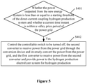
- the method for controlling a direct-current coupling hydrogen production system further includes the following steps S401 and S402 as shown in Figure 5 .
- step S401 it is determined whether the power outputted from the new energy system is less than or equal to a starting threshold and whether a current time instant is within a valley price period of the power grid.
- step S402 is performed.
- step S402 the controllable switch is controlled to be turned off, the second converter is controlled to receive power from the power grid through the conversion device and inversely convert the power from the power grid, and the first converter is controlled to receive power from the second converter and provide power to the hydrogen production electrolyzer system for hydrogen production.
Landscapes
- Engineering & Computer Science (AREA)
- Chemical & Material Sciences (AREA)
- Power Engineering (AREA)
- Chemical Kinetics & Catalysis (AREA)
- Electrochemistry (AREA)
- Materials Engineering (AREA)
- Metallurgy (AREA)
- Organic Chemistry (AREA)
- Inorganic Chemistry (AREA)
- Business, Economics & Management (AREA)
- Health & Medical Sciences (AREA)
- Economics (AREA)
- Public Health (AREA)
- Water Supply & Treatment (AREA)
- General Health & Medical Sciences (AREA)
- Human Resources & Organizations (AREA)
- Marketing (AREA)
- Primary Health Care (AREA)
- Strategic Management (AREA)
- Tourism & Hospitality (AREA)
- Physics & Mathematics (AREA)
- General Business, Economics & Management (AREA)
- General Physics & Mathematics (AREA)
- Theoretical Computer Science (AREA)
- Automation & Control Theory (AREA)
- Electrolytic Production Of Non-Metals, Compounds, Apparatuses Therefor (AREA)
- Vehicle Body Suspensions (AREA)
Applications Claiming Priority (2)
| Application Number | Priority Date | Filing Date | Title |
|---|---|---|---|
| CN201911031338.2A CN112803472A (zh) | 2019-10-28 | 2019-10-28 | 一种直流耦合制氢系统及其控制方法 |
| PCT/CN2020/093091 WO2021082423A1 (zh) | 2019-10-28 | 2020-05-29 | 一种直流耦合制氢系统及其控制方法 |
Publications (2)
| Publication Number | Publication Date |
|---|---|
| EP3965249A1 true EP3965249A1 (de) | 2022-03-09 |
| EP3965249A4 EP3965249A4 (de) | 2023-04-12 |
Family
ID=75715585
Family Applications (1)
| Application Number | Title | Priority Date | Filing Date |
|---|---|---|---|
| EP20883310.3A Pending EP3965249A4 (de) | 2019-10-28 | 2020-05-29 | Gleichstromkopplungssystem zur herstellung von wasserstoff und steuerungsverfahren dafür |
Country Status (4)
| Country | Link |
|---|---|
| EP (1) | EP3965249A4 (de) |
| CN (1) | CN112803472A (de) |
| AU (1) | AU2020377230B2 (de) |
| WO (1) | WO2021082423A1 (de) |
Cited By (3)
| Publication number | Priority date | Publication date | Assignee | Title |
|---|---|---|---|---|
| WO2023237372A1 (de) * | 2022-06-08 | 2023-12-14 | Siemens Energy Global GmbH & Co. KG | Anlagenverbund umfassend mindestens zwei elektrolyseanlagen und eine stromversorgungsquelle |
| WO2024002797A1 (de) * | 2022-06-30 | 2024-01-04 | Siemens Energy Global GmbH & Co. KG | Anlagenverbund umfassend mindestens zwei elektrolyseanlagen und eine stromversorgungsquelle |
| CN119602393A (zh) * | 2024-12-05 | 2025-03-11 | 广东华矩检测技术有限公司 | 一种光伏发电制氢控制方法、系统、程序产品及存储介质 |
Families Citing this family (26)
| Publication number | Priority date | Publication date | Assignee | Title |
|---|---|---|---|---|
| CN113445062A (zh) * | 2021-06-22 | 2021-09-28 | 新天绿色能源股份有限公司 | 电解水制氢装置、电解水制氢装置的控制方法、电子设备 |
| CN113381624B (zh) * | 2021-07-05 | 2024-02-09 | 阳光电源股份有限公司 | 一种制氢的电源系统、制氢的装置和制氢的方法 |
| CN113690938A (zh) * | 2021-08-31 | 2021-11-23 | 河北建投新能源有限公司 | 一种基于功率模型预测的制氢系统控制方法 |
| CN113832475B (zh) * | 2021-09-23 | 2022-07-26 | 中国大唐集团新能源科学技术研究院有限公司 | 可再生能源制氢系统 |
| CN117941198A (zh) * | 2021-09-29 | 2024-04-26 | 西门子(中国)有限公司 | 制氢系统及其控制方法 |
| CN117941199A (zh) * | 2021-09-29 | 2024-04-26 | 西门子(中国)有限公司 | 制氢系统 |
| CN114032559B (zh) * | 2021-11-08 | 2023-05-26 | 阳光电源股份有限公司 | 一种新能源离网制氢的系统及方法 |
| CN114086203A (zh) * | 2021-11-19 | 2022-02-25 | 中国华能集团清洁能源技术研究院有限公司 | 一种间歇、波动电解制氢控制方法 |
| CN114336605B (zh) * | 2021-12-29 | 2023-07-21 | 西安交通大学 | 一种柔性电氢制储注一体站容量配置方法及系统 |
| CN114381759B (zh) * | 2022-02-11 | 2023-09-29 | 中国华能集团清洁能源技术研究院有限公司 | 一种光伏制氢系统的控制系统及控制方法 |
| CN114583682A (zh) * | 2022-03-08 | 2022-06-03 | 阳光氢能科技有限公司 | 一种光伏直流离网制氢系统及其控制方法 |
| CN114737203B (zh) * | 2022-04-24 | 2023-09-26 | 国网浙江省电力有限公司金华供电公司 | 一种基于电解水制氢装置的快速调频响应控制系统 |
| CN114990600B (zh) * | 2022-04-29 | 2024-05-10 | 阳光氢能科技有限公司 | 一种新能源制氢系统及其控制方法 |
| CN114977246A (zh) * | 2022-05-09 | 2022-08-30 | 中国华能集团清洁能源技术研究院有限公司 | 一种光伏电站制氢储能的方法及设备 |
| CN115094433A (zh) * | 2022-05-31 | 2022-09-23 | 同济大学 | 耦合电化学电源和超级电容器的混合制氢系统及控制方法 |
| CN115377992B (zh) * | 2022-06-27 | 2024-04-09 | 国网浙江省电力有限公司丽水供电公司 | 适用于宽范围灵活制氢的功率变流器故障穿越控制方法 |
| CN115305501B (zh) * | 2022-07-05 | 2025-07-25 | 广东电网有限责任公司 | 基于风电并网的制氢控制方法、装置、设备及介质 |
| CN115663911A (zh) * | 2022-08-11 | 2023-01-31 | 南方电网能源发展研究院有限责任公司 | 风能与氢能耦合供电管理方法、装置、设备、介质和产品 |
| CN115693733B (zh) * | 2022-09-08 | 2025-12-02 | 重庆大学 | 一种风光耦合离网电解制氢系统的功率控制方法 |
| CN115694198B (zh) * | 2022-10-19 | 2025-08-05 | 西南交通大学 | 一种适用于碱性电解制氢系统的变换器设计方法 |
| CN115473279B (zh) * | 2022-10-21 | 2024-03-29 | 重庆大学 | 一种含电解水制氢负载的风光储离网微电网运行控制方法 |
| CN116526416A (zh) * | 2023-07-05 | 2023-08-01 | 福建福清核电有限公司 | 一种基于就地电气量特征的安全稳定控制系统防误动方法 |
| CN117889040B (zh) * | 2024-03-14 | 2024-07-16 | 中国船舶集团风电发展有限公司 | 风电离网制氢的控制方法、装置、设备及存储介质 |
| CN119154340B (zh) * | 2024-09-14 | 2026-01-30 | 中国长江三峡集团有限公司 | 一种制氢电解槽集群的控制方法及装置 |
| CN119712420B (zh) * | 2024-12-23 | 2025-10-17 | 东方电气风电股份有限公司 | 一种用于制氢的风力发电机组控制方法 |
| CN119372680A (zh) * | 2024-12-27 | 2025-01-28 | 四川能投氢能产业投资有限公司 | 一种光伏电解水制氢系统及运行方法 |
Family Cites Families (12)
| Publication number | Priority date | Publication date | Assignee | Title |
|---|---|---|---|---|
| US8996182B2 (en) * | 2009-06-08 | 2015-03-31 | Toyota Jidosha Kabushiki Kaisha | Fuel cell system and power control method therefor |
| CN202001202U (zh) * | 2011-03-07 | 2011-10-05 | 国电联合动力技术有限公司 | 一种用于制氢的非并网式风力发电机组 |
| DE102013112431A1 (de) * | 2012-11-13 | 2014-06-05 | Aeg Power Solutions B.V. | Anordnung aus einem Kraftwerk und einer Vorrichtung zur Erzeugung von Gas mittels von dem Kraftwerk erzeugter elektrischer Energie |
| JP2017034843A (ja) * | 2015-07-31 | 2017-02-09 | 株式会社東京機械製作所 | 水素製造システム、水素供給ステーション及び水素製造方法 |
| CN105463498B (zh) * | 2016-01-25 | 2017-10-31 | 新疆工程学院 | 直流‑直流变换器与spe电解槽的耦合装置及其耦合方法 |
| CN107017651A (zh) * | 2017-05-22 | 2017-08-04 | 北京鑫海港亿科技有限公司 | 一种风电制氢储能的氢燃料复合电池及其发电方法 |
| KR101926010B1 (ko) * | 2018-02-28 | 2018-12-06 | 이화전기공업 주식회사 | 신재생에너지를 이용한 전력변환 시스템 |
| CN108517533B (zh) * | 2018-03-26 | 2020-07-28 | 全球能源互联网研究院有限公司 | 一种电解制氢控制方法及装置 |
| CN109004665B (zh) * | 2018-08-31 | 2022-04-01 | 河北科技大学 | 风电、光电储能及离/并网制氢系统 |
| CN109474010B (zh) * | 2018-11-15 | 2022-07-26 | 中广核研究院有限公司 | 一种具有氢能循环利用的并网型微电网系统及其控制方法 |
| CN109286205A (zh) * | 2018-11-23 | 2019-01-29 | 河北工业大学 | 离并网自适应的风力发电机组控制装置及方法 |
| CN109755965B (zh) * | 2019-03-20 | 2022-04-01 | 河北科技大学 | 风光发电和制氢储氢系统的运行控制方法 |
-
2019
- 2019-10-28 CN CN201911031338.2A patent/CN112803472A/zh active Pending
-
2020
- 2020-05-29 AU AU2020377230A patent/AU2020377230B2/en active Active
- 2020-05-29 WO PCT/CN2020/093091 patent/WO2021082423A1/zh not_active Ceased
- 2020-05-29 EP EP20883310.3A patent/EP3965249A4/de active Pending
Cited By (5)
| Publication number | Priority date | Publication date | Assignee | Title |
|---|---|---|---|---|
| WO2023237372A1 (de) * | 2022-06-08 | 2023-12-14 | Siemens Energy Global GmbH & Co. KG | Anlagenverbund umfassend mindestens zwei elektrolyseanlagen und eine stromversorgungsquelle |
| US12431716B2 (en) | 2022-06-08 | 2025-09-30 | Siemens Energy Global GmbH & Co. KG | System network comprising at least two electrolysis systems and a power supply source |
| WO2024002797A1 (de) * | 2022-06-30 | 2024-01-04 | Siemens Energy Global GmbH & Co. KG | Anlagenverbund umfassend mindestens zwei elektrolyseanlagen und eine stromversorgungsquelle |
| CN119602393A (zh) * | 2024-12-05 | 2025-03-11 | 广东华矩检测技术有限公司 | 一种光伏发电制氢控制方法、系统、程序产品及存储介质 |
| CN119602393B (zh) * | 2024-12-05 | 2026-03-17 | 广东华矩检测技术有限公司 | 一种光伏发电制氢控制方法、系统、程序产品及存储介质 |
Also Published As
| Publication number | Publication date |
|---|---|
| AU2020377230A1 (en) | 2022-01-06 |
| WO2021082423A1 (zh) | 2021-05-06 |
| EP3965249A4 (de) | 2023-04-12 |
| CN112803472A (zh) | 2021-05-14 |
| AU2020377230B2 (en) | 2023-07-13 |
Similar Documents
| Publication | Publication Date | Title |
|---|---|---|
| AU2020377230B2 (en) | Direct-current coupling hydrogen production system and control method therefor | |
| CN112290583B (zh) | 直流耦合离网制氢系统及其控制柜供电装置和控制方法 | |
| CN114552659B (zh) | 含电氢储能的多能量综合管理型能量路由器及控制方法 | |
| CN111463807B (zh) | 一种分布式直流耦合制氢系统及其控制方法 | |
| CN105207258B (zh) | 一种光伏直流微电网能量协调控制装置 | |
| CN112290582B (zh) | 新能源电站和直流耦合离网制氢系统及其控制方法 | |
| AU2020387439B2 (en) | New energy composite hydrogen production system and control method therefor | |
| EP3089310B1 (de) | Stromwandlungssystem, wandlervorrichtung, wechselrichtervorrichtung und stromwandlungssystemherstellungsverfahren | |
| US20130057196A1 (en) | Photovoltaic powered system with adaptive power control and method of operating the same | |
| CN116599093B (zh) | 一种碱液电解制氢参与电网深度调峰的控制方法 | |
| CN209298898U (zh) | 一种分布式光伏远距离直流输电系统 | |
| CN112491032A (zh) | 一种直流耦合离网制氢系统及其控制方法 | |
| CN115764951A (zh) | 一种交流耦合的光储充系统 | |
| CN113949054A (zh) | 电网自治系统及方法 | |
| CN211480940U (zh) | 一种具有黑启动功能的双馈式风电机组变流器 | |
| CN220673401U (zh) | 一种储-充固体氧化物燃料电池微电网系统 | |
| CN113497552B (zh) | 一种柔性直流输电系统换流器孤岛启动方法 | |
| CN112994057A (zh) | 一种模块化能量路由器系统的经济运行控制方法 | |
| CN219576711U (zh) | 一种风光制氢混合储能系统 | |
| CN220342044U (zh) | 一种储能控制管理系统及储能集装箱 | |
| CN223872052U (zh) | 一种光伏发电储能系统 | |
| CN222928104U (zh) | 一种氢发电系统 | |
| CN114726085B (zh) | 一种水电站备用电源供电系统 | |
| CN107910933B (zh) | 通信电源充电稳压模块 | |
| CN116995718A (zh) | 电池的控制系统和控制方法 |
Legal Events
| Date | Code | Title | Description |
|---|---|---|---|
| STAA | Information on the status of an ep patent application or granted ep patent |
Free format text: STATUS: THE INTERNATIONAL PUBLICATION HAS BEEN MADE |
|
| PUAI | Public reference made under article 153(3) epc to a published international application that has entered the european phase |
Free format text: ORIGINAL CODE: 0009012 |
|
| STAA | Information on the status of an ep patent application or granted ep patent |
Free format text: STATUS: REQUEST FOR EXAMINATION WAS MADE |
|
| 17P | Request for examination filed |
Effective date: 20211129 |
|
| AK | Designated contracting states |
Kind code of ref document: A1 Designated state(s): AL AT BE BG CH CY CZ DE DK EE ES FI FR GB GR HR HU IE IS IT LI LT LU LV MC MK MT NL NO PL PT RO RS SE SI SK SM TR |
|
| DAV | Request for validation of the european patent (deleted) | ||
| DAX | Request for extension of the european patent (deleted) | ||
| A4 | Supplementary search report drawn up and despatched |
Effective date: 20230313 |
|
| RIC1 | Information provided on ipc code assigned before grant |
Ipc: H02J 15/00 20060101ALI20230306BHEP Ipc: H02J 3/38 20060101AFI20230306BHEP |
|
| STAA | Information on the status of an ep patent application or granted ep patent |
Free format text: STATUS: EXAMINATION IS IN PROGRESS |
|
| 17Q | First examination report despatched |
Effective date: 20250213 |