EP3964824A1 - Expansion coefficient determination with deformation measurement and simulation - Google Patents
Expansion coefficient determination with deformation measurement and simulation Download PDFInfo
- Publication number
- EP3964824A1 EP3964824A1 EP20194020.2A EP20194020A EP3964824A1 EP 3964824 A1 EP3964824 A1 EP 3964824A1 EP 20194020 A EP20194020 A EP 20194020A EP 3964824 A1 EP3964824 A1 EP 3964824A1
- Authority
- EP
- European Patent Office
- Prior art keywords
- image data
- compound material
- expansion coefficient
- deformation
- environmental condition
- Prior art date
- Legal status (The legal status is an assumption and is not a legal conclusion. Google has not performed a legal analysis and makes no representation as to the accuracy of the status listed.)
- Granted
Links
Images


Classifications
-
- G—PHYSICS
- G06—COMPUTING OR CALCULATING; COUNTING
- G06T—IMAGE DATA PROCESSING OR GENERATION, IN GENERAL
- G06T7/00—Image analysis
- G06T7/0002—Inspection of images, e.g. flaw detection
- G06T7/0004—Industrial image inspection
- G06T7/001—Industrial image inspection using an image reference approach
-
- G—PHYSICS
- G06—COMPUTING OR CALCULATING; COUNTING
- G06F—ELECTRIC DIGITAL DATA PROCESSING
- G06F30/00—Computer-aided design [CAD]
- G06F30/20—Design optimisation, verification or simulation
- G06F30/23—Design optimisation, verification or simulation using finite element methods [FEM] or finite difference methods [FDM]
-
- G—PHYSICS
- G01—MEASURING; TESTING
- G01N—INVESTIGATING OR ANALYSING MATERIALS BY DETERMINING THEIR CHEMICAL OR PHYSICAL PROPERTIES
- G01N25/00—Investigating or analyzing materials by the use of thermal means
- G01N25/16—Investigating or analyzing materials by the use of thermal means by investigating thermal coefficient of expansion
-
- G—PHYSICS
- G06—COMPUTING OR CALCULATING; COUNTING
- G06F—ELECTRIC DIGITAL DATA PROCESSING
- G06F30/00—Computer-aided design [CAD]
- G06F30/30—Circuit design
- G06F30/39—Circuit design at the physical level
-
- G—PHYSICS
- G06—COMPUTING OR CALCULATING; COUNTING
- G06T—IMAGE DATA PROCESSING OR GENERATION, IN GENERAL
- G06T7/00—Image analysis
- G06T7/50—Depth or shape recovery
- G06T7/55—Depth or shape recovery from multiple images
- G06T7/593—Depth or shape recovery from multiple images from stereo images
-
- G—PHYSICS
- G06—COMPUTING OR CALCULATING; COUNTING
- G06T—IMAGE DATA PROCESSING OR GENERATION, IN GENERAL
- G06T7/00—Image analysis
- G06T7/60—Analysis of geometric attributes
-
- G—PHYSICS
- G06—COMPUTING OR CALCULATING; COUNTING
- G06V—IMAGE OR VIDEO RECOGNITION OR UNDERSTANDING
- G06V10/00—Arrangements for image or video recognition or understanding
- G06V10/70—Arrangements for image or video recognition or understanding using pattern recognition or machine learning
- G06V10/74—Image or video pattern matching; Proximity measures in feature spaces
- G06V10/75—Organisation of the matching processes, e.g. simultaneous or sequential comparisons of image or video features; Coarse-fine approaches, e.g. multi-scale approaches; using context analysis; Selection of dictionaries
- G06V10/751—Comparing pixel values or logical combinations thereof, or feature values having positional relevance, e.g. template matching
-
- G—PHYSICS
- G01—MEASURING; TESTING
- G01N—INVESTIGATING OR ANALYSING MATERIALS BY DETERMINING THEIR CHEMICAL OR PHYSICAL PROPERTIES
- G01N17/00—Investigating resistance of materials to the weather, to corrosion, or to light
- G01N17/002—Test chambers
-
- G—PHYSICS
- G01—MEASURING; TESTING
- G01N—INVESTIGATING OR ANALYSING MATERIALS BY DETERMINING THEIR CHEMICAL OR PHYSICAL PROPERTIES
- G01N2203/00—Investigating strength properties of solid materials by application of mechanical stress
- G01N2203/02—Details not specific for a particular testing method
- G01N2203/0202—Control of the test
- G01N2203/0212—Theories, calculations
- G01N2203/0218—Calculations based on experimental data
-
- G—PHYSICS
- G01—MEASURING; TESTING
- G01N—INVESTIGATING OR ANALYSING MATERIALS BY DETERMINING THEIR CHEMICAL OR PHYSICAL PROPERTIES
- G01N2203/00—Investigating strength properties of solid materials by application of mechanical stress
- G01N2203/02—Details not specific for a particular testing method
- G01N2203/022—Environment of the test
- G01N2203/0222—Temperature
- G01N2203/0226—High temperature; Heating means
-
- G—PHYSICS
- G01—MEASURING; TESTING
- G01N—INVESTIGATING OR ANALYSING MATERIALS BY DETERMINING THEIR CHEMICAL OR PHYSICAL PROPERTIES
- G01N2203/00—Investigating strength properties of solid materials by application of mechanical stress
- G01N2203/02—Details not specific for a particular testing method
- G01N2203/022—Environment of the test
- G01N2203/0236—Other environments
-
- G—PHYSICS
- G01—MEASURING; TESTING
- G01N—INVESTIGATING OR ANALYSING MATERIALS BY DETERMINING THEIR CHEMICAL OR PHYSICAL PROPERTIES
- G01N2203/00—Investigating strength properties of solid materials by application of mechanical stress
- G01N2203/02—Details not specific for a particular testing method
- G01N2203/022—Environment of the test
- G01N2203/0236—Other environments
- G01N2203/0242—With circulation of a fluid
-
- G—PHYSICS
- G01—MEASURING; TESTING
- G01N—INVESTIGATING OR ANALYSING MATERIALS BY DETERMINING THEIR CHEMICAL OR PHYSICAL PROPERTIES
- G01N2203/00—Investigating strength properties of solid materials by application of mechanical stress
- G01N2203/02—Details not specific for a particular testing method
- G01N2203/06—Indicating or recording means; Sensing means
- G01N2203/0641—Indicating or recording means; Sensing means using optical, X-ray, ultraviolet, infrared or similar detectors
- G01N2203/0647—Image analysis
-
- G—PHYSICS
- G01—MEASURING; TESTING
- G01N—INVESTIGATING OR ANALYSING MATERIALS BY DETERMINING THEIR CHEMICAL OR PHYSICAL PROPERTIES
- G01N2203/00—Investigating strength properties of solid materials by application of mechanical stress
- G01N2203/02—Details not specific for a particular testing method
- G01N2203/06—Indicating or recording means; Sensing means
- G01N2203/067—Parameter measured for estimating the property
- G01N2203/0682—Spatial dimension, e.g. length, area, angle
-
- G—PHYSICS
- G06—COMPUTING OR CALCULATING; COUNTING
- G06F—ELECTRIC DIGITAL DATA PROCESSING
- G06F2115/00—Details relating to the type of the circuit
- G06F2115/12—Printed circuit boards [PCB] or multi-chip modules [MCM]
-
- G—PHYSICS
- G06—COMPUTING OR CALCULATING; COUNTING
- G06F—ELECTRIC DIGITAL DATA PROCESSING
- G06F2119/00—Details relating to the type or aim of the analysis or the optimisation
- G06F2119/08—Thermal analysis or thermal optimisation
-
- G—PHYSICS
- G06—COMPUTING OR CALCULATING; COUNTING
- G06T—IMAGE DATA PROCESSING OR GENERATION, IN GENERAL
- G06T2207/00—Indexing scheme for image analysis or image enhancement
- G06T2207/10—Image acquisition modality
- G06T2207/10004—Still image; Photographic image
- G06T2207/10012—Stereo images
-
- G—PHYSICS
- G06—COMPUTING OR CALCULATING; COUNTING
- G06T—IMAGE DATA PROCESSING OR GENERATION, IN GENERAL
- G06T2207/00—Indexing scheme for image analysis or image enhancement
- G06T2207/30—Subject of image; Context of image processing
- G06T2207/30108—Industrial image inspection
Definitions
- the invention relates to a method, a computer program, a computer-readable medium and a test system for determining an expansion coefficient of a test material.
- Multi-layer circuit boards may be formed of stacks of metal layers and isolation layers.
- the isolation layers may be made of a (reversibly or irreversibly) deformable material, in particular thermally deformable material, such as a prepreg material.
- a prepreg material may be cured and shrinkage of the resin of the prepreg material, in which fibres are embedded, may lead to stress states inside the cured stacks.
- stress states may be caused by deformation of the isolation layers due to expansion or shrinkage.
- possible layouts of multi-layer circuit boards may be simulated. For such simulations, the chemical shrinkage of the prepreg material as well as thermal expansion coefficients may need to be known with high accuracy.
- CN 110 631 906A describes a material parameter acquisition method based on digital image correlation and finite elements. By combining a digital image related method and a finite element method, material parameters of the sample are obtained.
- WO 2019 124 062 A1 relates to a prepreg material used in manufacturing of a semiconductor package provided with a chip and a substrate on which the chip is mounted. A coefficient of thermal expansion of the chip is measured with digital image correlation.
- a first aspect of the invention relates to a method for determining an expansion coefficient of a test material.
- the test material may be a prepreg material, such as FR-4, which may be used in manufacturing circuit boards.
- the expansion coefficient may also be seen as a shrinkage coefficient, when the expansion is negative.
- the expansion coefficient may indicate a thermal expansion and/or chemical shrinkage of the test material during curing.
- the expansion coefficient may be a function of environmental conditions, such as temperature and humidity and/or may be time-dependent with respect to a time an environmental condition is applied to the test material.
- the method comprises: receiving first image data of a compound material, wherein the compound material comprises a plate and a layer of the test material, which is attached to the plate.
- the method further comprises: receiving at least one second image data of the compound material, which has been exposed to an environmental condition, before the second image data has been recorded. It maybe that image data is recorded continuously and/or that image data is recorded at a plurality of time steps.
- the image data of a time step may be compared with the image data of the first time step and/or with the image data of the previous time step.
- the first and second image data may encode an image of the compound material in digital form.
- the image data may comprise depth information.
- the image data may have been recorded with a camera, such as a stereo camera.
- the first image data may have been recorded before the compound material has been exposed to the environmental condition.
- the first image data may have been recorded with the compound material in a standard environmental condition, such as room temperature and/or a standard humidity.
- the second image data may have been recorded after and/or during an environmental condition different from the standard environmental condition, such as a curing process with a higher temperature.
- the compound material may be composed of two layers, a layer of test material and a layer of a further material, which forms the plate.
- the compound material may be seen as a bi-material strip.
- the plate may be undeformable compared to the test material.
- the plate may be made of any material with a deformation coefficient smaller than the test material, for example with a deformation coefficient substantially 0.
- the plate may be made of metal.
- the compound material deforms, for example analogously to a bimetal strip. This movement and/or deformation may be determined from differences in the first image data and the second image data. Due to the two-layer structure, rather small local deformations may result in a much higher cumulated deformation of the compound material.
- the method further comprises: determining a measured deformation of the compound material by comparing the first image data and the second image data.
- the deformation may be determined from depth information encoded into the image data.
- the deformation also may be determined from a deformation of the shape of the compound material. For points in the first image data it may be determined, where the respective point has moved. Therefrom, a movement of a point of the compound material before the exposure to the environmental condition to a point during and/or after the exposure may be determined.
- the measured deformation may encode this movement of points and/or may encode a shape of the compound material after the exposure to the environmental condition.
- the method further comprises: performing a simulated deformation of a model of the compound material exposed to the environmental condition and determining the expansion coefficient of the test material by varying the expansion coefficient until the simulate deformation conforms to the measured deformation. Additionally to the measured deformation, which is determined from the image data, simulated deformations may be determined. The simulated deformations may be determined by performing a simulation of a model of the compound material with different expansion coefficients for the test material. Other properties of the compound material may be fixed, such as the shape, the thicknesses of the layers of the compound material, an expansion coefficient of the plate, etc. The simulation may be performed with a finite elements method. With the simulation, deformations for different expansion coefficients may be tested and compared to the measured deformation.
- the expansion coefficient may be determined with an optimization process, wherein an objective function, which quantifies a difference of the measured deformation and the simulated deformation, is minimized.
- the measured deformation of the compound material is determined by determining a distance of points of the compound material with respect to a plane, in which the compound material extends.
- the compound material Before the exposure to the environmental condition, the compound material may have a flat shape, i.e. may have two flat surfaces and/or may extend along to the plane.
- the compound material may warp and/or may be warped and this may be determined by a movement of the specific points of the compound material orthogonal to the plane defined by the undeformed compound material.
- the measured deformation may comprise points and their movement between the acquisition of the first image data and the second image data. From the simulation, also a movement of these points may be determined.
- An objective function for quantifying a difference of measured and simulated deformation may be based on the movement distances determined from the image data and the simulation.
- the compound material may be provided in the form of a strip, wherein a part of the strip is fixated and another part is allowed to move freely, when the strip is exposed to the environmental condition.
- a part of the strip is fixated and another part is allowed to move freely, when the strip is exposed to the environmental condition.
- an end of the strip may be fixated and the other end is allowed to move freely.
- a center of the strip may be fixated.
- the first image data and the second image data comprises depth information.
- the first image data and the second image data comprise stereo images.
- Depth information may be information, which encode a distance of a point in the image data to the recording device, such as a camera.
- the first image data and second image data comprise 3D pixels, which for example may be provided by a time-of-flight camera.
- a pattern is provided on the compound material and the first image data and the second image data comprise an image of the pattern.
- the measured deformation may be determined by comparing the pattern in the first image data and the pattern in the second image data.
- the pattern may be printed, sprayed, coated or manually applied to the layer of the test material.
- the compound material is provided as a strip, which is fixated at a part, the pattern then may be provided on the part allowed to move freely or on the complete compound material.
- the compound material and therefore the pattern applied to it may move and/or may deform. Differences of the patterns in the first and second image data may be determined with digital image correlation.
- the pattern comprises speckles.
- Speckles may be irregular dots with varying diameter.
- the measured deformation is determined with digital image correlation of the speckles in the first image data and the pattern in the second image data.
- the test material comprises fibres embedded into a resin.
- the fibres and/or a fabric which may be glass fibres and/or carbon fibres, may influence the expansion coefficient of the resin alone with respect to a different direction.
- the fibres may be oriented along warp and weft directions. Therefore, expansion coefficients may be determined with respect to at least two directions.
- the expansion coefficient may be seen as a tensor.
- These direction dependent expansion coefficients may be input into the simulation, in which also an orientation of the fibres (such as warp and weft directions) is modelled. The warp/weft interaction of a fabric with the resin may be determined with the method.
- the environmental condition comprises at least one of: a temperature, to which the compound material is exposed; a humidity, to which the compound material is exposed; and/or a fluid, to which the compound material is exposed.
- the fluid may be a gas, such as air or nitrogen, and liquid, such as water or an oil. The method not only may be used for determining the shrinkage of a prepreg material but also for other types of material.
- the environmental condition comprises at least one of: an electromagnetic filed, to which the compound material is exposed; a current and/or voltage applied to the compound material.
- the plate of the compound material may be electrically conducting.
- a voltage may be applied to the plate and/or may be induced in the plate, such that a current flows through the plate.
- image data at a plurality of time steps during the exposure to the environmental condition is recorded.
- a measured deformation of the compound material may be determined for the plurality of time steps.
- the simulation may be performed over time and the determination of the expansion coefficient may be based on comparing the measured deformation with the simulated deformation at the plurality of time steps. This may increase the accuracy of the expansion coefficient determination. It also may be that further characteristics of the compound material are indicated and a deeper understanding of its material properties is reached.
- a time dependent expansion coefficient is determined. It also may be that the expansion coefficient (even under a time independent environmental condition) is time dependent. For example, the expansion coefficient may increase or lower with increasing time difference to the start, when the compound material is exposed to the environmental condition.
- the compound material is exposed to an environmental condition, which changes over time.
- an environmental condition which changes over time.
- the temperature and/or the humidity may be varied during the exposure. These variations also may be included into the simulation of the compound material.
- the environmental condition, which changes over time, may be controlled by a device, which also performs the simulation with the same parameters.
- the test material comprises a thermally deformable material.
- the test material may be heated and may deform reversibly or irreversibly due to the temperature change.
- the thermally deformable material may be a prepreg material.
- a prepreg material may comprise a resin, which is cured during the exposure to a specific environmental condition, such as a high temperature.
- the prepreg material may be FR-4 dielectric containing a glass cloth.
- the environmental condition may comprise a heating of the compound material for curing the test material, such as a prepreg material.
- the expansion coefficient may specify a chemical shrinkage of the test material.
- the test material may comprise a resin, which may be be reinforced or non-reinforced.
- resins may include an epoxy resin and/or a bismaleimide-triazine resin.
- test materials may be made of and/or may comprise cyanate ester, polyphenylene derivate, glass (in particular glass fibers, multi-layer glass, glass-like materials), prepreg material (such as FR-4 or FR-5) polyimide, polyamide, liquid crystal polymer (LCP), epoxy-based build-up film, polytetrafluoroethylene (Teflon), ceramics and/or a metal oxide.
- prepreg material such as FR-4 or FR-5 polyimide, polyamide, liquid crystal polymer (LCP), epoxy-based build-up film, polytetrafluoroethylene (Teflon), ceramics and/or a metal oxide.
- the model of the compound material used for the simulation models the test material and the plate.
- the model also may contain information on fibres (for example from a fabric) embedded into a resin), in particular a direction of the fibres and/or warp and weft directions.
- the simulation for determining the simulated deformation may be performed with a preset expansion coefficient of the plate of the compound material.
- the plate of the compound material may be a homogenous plate with isotropic known expansion coefficients.
- a further aspect of the invention relates to a computer program for determining an expansion coefficient of a test material, which, when being executed by a processor, is adapted to perform the steps of the method as described herein.
- the computer program may be adapted for: receiving the first image and the second image data; determining a measured deformation of the compound material by comparing the first image data and the second image data; performing the simulated deformation of the model of the compound material exposed to the environmental condition; and determining the expansion coefficient of the test material by varying the expansion coefficient until the simulate deformation conforms with the measured deformation.
- the computer program controls a test system.
- the computer program may control a camera device to record the image data.
- the computer program also may control an exposure device by setting environmental conditions to which the compound material is exposed.
- a further aspect of the invention relates to computer-readable medium, in which such a computer program is stored.
- a computer-readable medium may be a hard disk, an USB (Universal Serial Bus) storage device, a RAM (Random Access Memory), a ROM (Read Only Memory), an EPROM (Erasable Programmable Read Only Memory) or a FLASH memory.
- a computer-readable medium may also be a data communication network, e.g. the Internet, which allows downloading a program code.
- the computer-readable medium may be a non-transitory or transitory medium.
- a further aspect of the invention relates to a usage of the expansion coefficient determined with the method described herein for simulating a circuit board comprising the test material and exposed to the environmental condition.
- chemical shrinkage coefficients of prepreg materials may be determined and these chemical shrinkage coefficients may be used in mechanical, thermal and/or thermo-mechanical simulations of circuit boards.
- the test material which has been tested with the method, may be attached to other kinds of plates and metal layers as have been used during the method.
- the test material may be a prepreg material used in circuit board manufacturing.
- the environmental condition may be a heating of the compound material for curing the prepreg material.
- a test material with fibres embedded into a resin may be modelled in the simulation of the circuit board and that fibre direction and/or direction dependent expansion coefficients may be included into the model of the circuit board.
- the expansion coefficient may indicate a prepreg shrinkage during curing.
- a further aspect of the invention relates to a test system.
- the test system comprises an exposure device, such as an oven, for exposing the compound material to an environmental condition, a camera device for recording image data of the compound material, and an evaluation device for receiving the image data and for performing the method as described herein.
- the test system comprises a light source for illuminating the compound material.
- the exposure device may be a controllable oven, in which environmental conditions of the compound material, such as temperature and/or humidity, may be set, for example under the control of the evaluation device.
- the camera device may comprise a 3D camera and/or a stereo camera for recording the image data, for example under control of the evaluation device.
- the evaluation device may be a PC or other type of computing device, in which the computer program mentioned above may be run.
- Fig. 1 shows a test system 10, which comprises an exposure device 12 accommodating a compound material 14, a camera device 16 and an evaluation device 18.
- the exposure device 12 may be an oven possibly in combination with a humidifier, which may be controlled to expose the compound material to different temperatures, heat the compound material and/or humidify the air inside the oven. It also is possible that the exposure device 12 exposes the compound material to specific gases and/or liquids.
- the exposure device 12 may be controlled by the evaluation device 18. In general, the exposure device 12 is adapted for or exposing the compound material 14 to different environmental conditions, such as described above.
- the compound material 14 may have the form of a plate and/or strip, which is fixed at one end, while the other end is free movable.
- the compound material 14 may be provided in the form of a disk, which is fixated at the center.
- the camera device 16 is arranged to record image data of the compound material 14.
- the camera device 16 may be a stereo camera system and/or may comprise two cameras 19, which are directed towards the compound material 14, which may be situated behind a window of the exposure device 12. It also is possible that the camera device 16 is a time-of-flight camera, which produces image data with pixelwise depth information.
- the camera device 16 may be controlled by the evaluation device 18 and/or the image data may be sent to the evaluation device 18.
- a light source may be provided, which illuminates the compound material 14.
- the evaluation device 18 is adapted for receiving the image data and for performing the method for determining an expansion coefficient of the compound material as described herein.
- the evaluation device 18 may be a PC or other computing device with a processor and memory, in which a computer program is stored, which, when executed, performs the method. It has to be noted that the determination of the expansion coefficient is performed contactless, since the image data can be recorded from a distance to the compound material 14.
- Fig. 2 shows a cross-sectional perspective view of the compound material 14.
- the compound material has the shape of a plate and is composed of a test material 20 attached to a plate 22.
- the plate 22 may be a metal plate, such as an aluminium plate.
- the plate is chosen to have known material properties with respect to the different environmental conditions.
- the test material 20 is a prepreg material with a fabric 24 of fibres 26 embedded into a curable resin 28. Due to the fabric, the expansion coefficient of the test material 20 may be inhomogeneous with respect to different directions.
- Fig. 3 shows an example of a compound material 14, in particular an aluminium plate 22 with a prepreg material 20, which has been cured by heating for a specific time. At ends, the compound material 14 has been sprayed with a pattern 30 in the form of irregular speckles 32. It also can be seen that the strip of compound material 14 is fixated at one end 34 with a fixation means 36 and that the other end 38 has been moved during the curing (more general the exposure to an environmental condition) of the prepreg material 20. This was caused by the deformation of the compound material 20 during the curing. As shown in Fig. 3 , the fixation means 36 may comprise a fixed bearing (left) and a floating bearing (right).
- the compound material 14 is a bi-material strip and the test material 20 and the plate 22 have different expansion coefficients, it may deform analogously to a bimetal strip under temperature changes. However, in the present method, also other processes not restricted to different temperatures can be considered.
- Fig. 3 also shows, how a deformation of the compound material 14 may be specified.
- a distance to a plane, in which the undeformed compound material 14 was aligned may be determined. This determination may be done with the camera device 16, for example by digital image correlation based on the pattern 30 and in particular the speckles 32.
- other points as shown in Fig. 3 may be used as shown in Fig. 3 .
- all points in the image data may be used.
- Fig. 4 shows a flow diagram for a method that may be performed by the evaluation device 18. With the method, an expansion coefficient 42 of the test material 20 is determined.
- step S10 the exposure device 12 is controlled to change an environmental condition for the compound material 14.
- an environmental condition for the compound material 14 For example, a temperature and/or a humidity is changed.
- a fluid such as a gas
- the environmental condition comprises a heating of the compound material 14 for curing a prepreg material.
- the environmental condition to which the compound material 14 is exposed may change over time, for example different temperatures and/or humidities may be set with advancing time.
- First image data 44a may be recorded before the environmental condition starts to change, i.e. during a standard environmental condition.
- Second image data 44b may be recorded after curing or after the exposure to the environmental condition different to the standard environmental condition. It also may be that a series of image data 44a , 44b, 44c is recorded.
- the image data 44a, 44b, 44c may be recorded at a plurality of time steps during the exposure to the environmental condition is recorded.
- the image data and in particular the first image data 44a and the second image data 44b are received in the evaluation device 18.
- the camera device 16 may be a 3D camera device and the image data 44a, 44b, 44c may comprise depth information.
- the image data 44a, 44b, 44c comprise stereo images or a pixelwise depth information.
- step S12 the evaluation device 18 determines a measured deformation 46 of the compound material 14 by comparing the image data and in particular the first image data 44a and the second image data 44b.
- the measured deformation is an indicator about the deformation or warpage of the compound material 14. For example, the distances of the points 40 (see Fig. 3 ) with respect to a plane, the compound material 14 was originally aligned may be such an indicator.
- the measured deformation 46 may be determined by comparing the pattern 30 in the image data 44a, 44b, 44c, for example with digital image correlation.
- the measured deformation 46 of the compound material 14 may be determined for a plurality of time steps, i.e. the measured deformation may be a (discrete) function over time. In particular, this may be done, when also the environmental condition changes over time.
- step S14 the evaluation device 18 performs a simulated deformation of a model 48 of the compound material 14.
- the simulation is performed by simulating the same environmental condition and/or the same change of environmental condition over time, as the compound material 14 in reality was exposed in the exposure device 12.
- the simulation may be performed with finite elements.
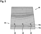
- the model 48 of the compound material 14 may be based on a mesh as shown in Fig. 5 .
- the test material 20 and the plate 22 and respective material parameters are encoded.
- Such material parameters comprise an expansion coefficient 42 of the test material 20 and of the material of the plate 22.
- the expansion coefficient 42 of the test material 20 may be inhomogeneous with respect to different directions and in such a way, also an interaction between the fibres 26 and/or the fabric 25 may be modelled.
- Fig. 5 also shows an indicator for a simulated deformation 50.
- the same points 40 as in the image data 44a, 44b, 44c may be identified in the model 48 and distances of these points between a simulated undeformed compound material 14a and a simulated deformed compound material 14b may be determined.
- an expansion coefficient 42 of the test material 20 is determined by varying the expansion coefficient 42 until the simulate deformation 50 conforms to the measured deformation 46.
- a direction dependent expansion coefficient 42 and/or expansion coefficients 42 with respect to at least two directions may be determined in this way.
- an objective function based on a difference of the measured deformation 46 and the simulated deformation 50 may be evaluated and minimized.
- the objective function may be based on differences of the distances of the points 40 in the measured deformation 46 and the simulated deformation 50.
- a time behaviour of the deformation can be considered.
- the simulation may be performed over time and the determination of the expansion coefficient 42 may be based on comparing the measured deformation 46 with the simulated deformation at a plurality of time steps. This again may be done with the points 40. In this case, a time dependent expansion coefficient 42 may be determined.
- step S16 a circuit board is simulated.
- Step S16 may be performed with a computing device different from the evaluation device.
- a model 52 of the circuit board is generated, into which the expansion coefficient 42 determined in step S14 is input.
- the model 52 may comprise one or more layers of the test material 20, in particular of different shape and/or thickness as the test material 20 in the compound material 14.
- the simulated circuit board may be exposed to the environmental condition as the one in step S10.
- the expansion coefficient 42 may specify a chemical shrinkage and the curing of the circuit board may be simulated.
- a warpage of the circuit board can be predicted. Warpage problems can be solved before manufacturing.
Landscapes
- Engineering & Computer Science (AREA)
- Physics & Mathematics (AREA)
- Theoretical Computer Science (AREA)
- General Physics & Mathematics (AREA)
- Computer Vision & Pattern Recognition (AREA)
- Geometry (AREA)
- Evolutionary Computation (AREA)
- Computer Hardware Design (AREA)
- General Health & Medical Sciences (AREA)
- Health & Medical Sciences (AREA)
- General Engineering & Computer Science (AREA)
- Chemical & Material Sciences (AREA)
- Life Sciences & Earth Sciences (AREA)
- Analytical Chemistry (AREA)
- Biochemistry (AREA)
- Immunology (AREA)
- Pathology (AREA)
- Quality & Reliability (AREA)
- Artificial Intelligence (AREA)
- Computing Systems (AREA)
- Databases & Information Systems (AREA)
- Medical Informatics (AREA)
- Software Systems (AREA)
- Multimedia (AREA)
- Length Measuring Devices By Optical Means (AREA)
Abstract
Description
- The invention relates to a method, a computer program, a computer-readable medium and a test system for determining an expansion coefficient of a test material.
- Multi-layer circuit boards may be formed of stacks of metal layers and isolation layers. The isolation layers may be made of a (reversibly or irreversibly) deformable material, in particular thermally deformable material, such as a prepreg material. For example, after forming of the stack the prepreg material may be cured and shrinkage of the resin of the prepreg material, in which fibres are embedded, may lead to stress states inside the cured stacks. In general, stress states may be caused by deformation of the isolation layers due to expansion or shrinkage. To avoid such stress states and to detect problematic regions inside a multi-layer circuit board, possible layouts of multi-layer circuit boards may be simulated. For such simulations, the chemical shrinkage of the prepreg material as well as thermal expansion coefficients may need to be known with high accuracy.
-
CN 110 631 906A describes a material parameter acquisition method based on digital image correlation and finite elements. By combining a digital image related method and a finite element method, material parameters of the sample are obtained. -
WO 2019 124 062 A1 relates to a prepreg material used in manufacturing of a semiconductor package provided with a chip and a substrate on which the chip is mounted. A coefficient of thermal expansion of the chip is measured with digital image correlation. - It is an object of the invention to accurately determine expansion coefficients of materials used in multi-layer circuit boards.
- This object is achieved by the subject-matter of the independent claims. Further exemplary embodiments are evident from the dependent claims and the following description.
- A first aspect of the invention relates to a method for determining an expansion coefficient of a test material. The test material may be a prepreg material, such as FR-4, which may be used in manufacturing circuit boards. The expansion coefficient may also be seen as a shrinkage coefficient, when the expansion is negative. The expansion coefficient may indicate a thermal expansion and/or chemical shrinkage of the test material during curing. The expansion coefficient may be a function of environmental conditions, such as temperature and humidity and/or may be time-dependent with respect to a time an environmental condition is applied to the test material.
- According to an embodiment of the invention, the method comprises: receiving first image data of a compound material, wherein the compound material comprises a plate and a layer of the test material, which is attached to the plate. The method further comprises: receiving at least one second image data of the compound material, which has been exposed to an environmental condition, before the second image data has been recorded. It maybe that image data is recorded continuously and/or that image data is recorded at a plurality of time steps. The image data of a time step may be compared with the image data of the first time step and/or with the image data of the previous time step.
- The first and second image data may encode an image of the compound material in digital form. The image data may comprise depth information. The image data may have been recorded with a camera, such as a stereo camera.
- The first image data may have been recorded before the compound material has been exposed to the environmental condition. The first image data may have been recorded with the compound material in a standard environmental condition, such as room temperature and/or a standard humidity. The second image data may have been recorded after and/or during an environmental condition different from the standard environmental condition, such as a curing process with a higher temperature.
- The compound material may be composed of two layers, a layer of test material and a layer of a further material, which forms the plate. The compound material may be seen as a bi-material strip. The plate may be undeformable compared to the test material. The plate may be made of any material with a deformation coefficient smaller than the test material, for example with a deformation coefficient substantially 0. As an example, the plate may be made of metal. Between the recording of the first image data and the second image data, the compound material deforms, for example analogously to a bimetal strip. This movement and/or deformation may be determined from differences in the first image data and the second image data. Due to the two-layer structure, rather small local deformations may result in a much higher cumulated deformation of the compound material.
- According to an embodiment of the invention, the method further comprises: determining a measured deformation of the compound material by comparing the first image data and the second image data. The deformation may be determined from depth information encoded into the image data. The deformation also may be determined from a deformation of the shape of the compound material. For points in the first image data it may be determined, where the respective point has moved. Therefrom, a movement of a point of the compound material before the exposure to the environmental condition to a point during and/or after the exposure may be determined.
- The measured deformation may encode this movement of points and/or may encode a shape of the compound material after the exposure to the environmental condition.
- According to an embodiment of the invention, the method further comprises: performing a simulated deformation of a model of the compound material exposed to the environmental condition and determining the expansion coefficient of the test material by varying the expansion coefficient until the simulate deformation conforms to the measured deformation. Additionally to the measured deformation, which is determined from the image data, simulated deformations may be determined. The simulated deformations may be determined by performing a simulation of a model of the compound material with different expansion coefficients for the test material. Other properties of the compound material may be fixed, such as the shape, the thicknesses of the layers of the compound material, an expansion coefficient of the plate, etc. The simulation may be performed with a finite elements method. With the simulation, deformations for different expansion coefficients may be tested and compared to the measured deformation.
- The expansion coefficient may be determined with an optimization process, wherein an objective function, which quantifies a difference of the measured deformation and the simulated deformation, is minimized.
- According to an embodiment of the invention, the measured deformation of the compound material is determined by determining a distance of points of the compound material with respect to a plane, in which the compound material extends. Before the exposure to the environmental condition, the compound material may have a flat shape, i.e. may have two flat surfaces and/or may extend along to the plane. During and/or after the exposure, the compound material may warp and/or may be warped and this may be determined by a movement of the specific points of the compound material orthogonal to the plane defined by the undeformed compound material.
- The measured deformation may comprise points and their movement between the acquisition of the first image data and the second image data. From the simulation, also a movement of these points may be determined. An objective function for quantifying a difference of measured and simulated deformation may be based on the movement distances determined from the image data and the simulation.
- The compound material may be provided in the form of a strip, wherein a part of the strip is fixated and another part is allowed to move freely, when the strip is exposed to the environmental condition. For example, an end of the strip may be fixated and the other end is allowed to move freely. As another example, a center of the strip may be fixated.
- According to an embodiment of the invention, the first image data and the second image data comprises depth information. For example, the first image data and the second image data comprise stereo images. Depth information may be information, which encode a distance of a point in the image data to the recording device, such as a camera. It also may be that the first image data and second image data comprise 3D pixels, which for example may be provided by a time-of-flight camera.
- According to an embodiment of the invention, a pattern is provided on the compound material and the first image data and the second image data comprise an image of the pattern. The measured deformation may be determined by comparing the pattern in the first image data and the pattern in the second image data. The pattern may be printed, sprayed, coated or manually applied to the layer of the test material. When the compound material is provided as a strip, which is fixated at a part, the pattern then may be provided on the part allowed to move freely or on the complete compound material. During the exposure to the environmental condition, the compound material and therefore the pattern applied to it may move and/or may deform. Differences of the patterns in the first and second image data may be determined with digital image correlation.
- According to an embodiment of the invention, the pattern comprises speckles. Speckles may be irregular dots with varying diameter. The measured deformation is determined with digital image correlation of the speckles in the first image data and the pattern in the second image data.
- According to an embodiment of the invention, the test material comprises fibres embedded into a resin. The fibres and/or a fabric, which may be glass fibres and/or carbon fibres, may influence the expansion coefficient of the resin alone with respect to a different direction. The fibres may be oriented along warp and weft directions. Therefore, expansion coefficients may be determined with respect to at least two directions. The expansion coefficient may be seen as a tensor. These direction dependent expansion coefficients may be input into the simulation, in which also an orientation of the fibres (such as warp and weft directions) is modelled. The warp/weft interaction of a fabric with the resin may be determined with the method.
- According to an embodiment of the invention, the environmental condition comprises at least one of: a temperature, to which the compound material is exposed; a humidity, to which the compound material is exposed; and/or a fluid, to which the compound material is exposed. The fluid may be a gas, such as air or nitrogen, and liquid, such as water or an oil. The method not only may be used for determining the shrinkage of a prepreg material but also for other types of material.
- According to an embodiment of the invention, the environmental condition comprises at least one of: an electromagnetic filed, to which the compound material is exposed; a current and/or voltage applied to the compound material. For example, the plate of the compound material may be electrically conducting. A voltage may be applied to the plate and/or may be induced in the plate, such that a current flows through the plate.
- According to an embodiment of the invention, image data at a plurality of time steps during the exposure to the environmental condition is recorded. A measured deformation of the compound material may be determined for the plurality of time steps. The simulation may be performed over time and the determination of the expansion coefficient may be based on comparing the measured deformation with the simulated deformation at the plurality of time steps. This may increase the accuracy of the expansion coefficient determination. It also may be that further characteristics of the compound material are indicated and a deeper understanding of its material properties is reached.
- According to an embodiment of the invention, a time dependent expansion coefficient is determined. It also may be that the expansion coefficient (even under a time independent environmental condition) is time dependent. For example, the expansion coefficient may increase or lower with increasing time difference to the start, when the compound material is exposed to the environmental condition.
- According to an embodiment of the invention, the compound material is exposed to an environmental condition, which changes over time. For example, the temperature and/or the humidity may be varied during the exposure. These variations also may be included into the simulation of the compound material. The environmental condition, which changes over time, may be controlled by a device, which also performs the simulation with the same parameters.
- According to an embodiment of the invention, the test material comprises a thermally deformable material. The test material may be heated and may deform reversibly or irreversibly due to the temperature change.
- The thermally deformable material may be a prepreg material. A prepreg material may comprise a resin, which is cured during the exposure to a specific environmental condition, such as a high temperature. For example, the prepreg material may be FR-4 dielectric containing a glass cloth.
- According to an embodiment of the invention, the environmental condition may comprise a heating of the compound material for curing the test material, such as a prepreg material. In this case, the expansion coefficient may specify a chemical shrinkage of the test material.
- In general, the test material may comprise a resin, which may be be reinforced or non-reinforced. Such resins may include an epoxy resin and/or a bismaleimide-triazine resin.
- Other test materials may be made of and/or may comprise cyanate ester, polyphenylene derivate, glass (in particular glass fibers, multi-layer glass, glass-like materials), prepreg material (such as FR-4 or FR-5) polyimide, polyamide, liquid crystal polymer (LCP), epoxy-based build-up film, polytetrafluoroethylene (Teflon), ceramics and/or a metal oxide.
- According to an embodiment of the invention, the model of the compound material used for the simulation models the test material and the plate. The model also may contain information on fibres (for example from a fabric) embedded into a resin), in particular a direction of the fibres and/or warp and weft directions. The simulation for determining the simulated deformation may be performed with a preset expansion coefficient of the plate of the compound material. The plate of the compound material may be a homogenous plate with isotropic known expansion coefficients.
- A further aspect of the invention relates to a computer program for determining an expansion coefficient of a test material, which, when being executed by a processor, is adapted to perform the steps of the method as described herein. In particular, the computer program may be adapted for: receiving the first image and the second image data; determining a measured deformation of the compound material by comparing the first image data and the second image data; performing the simulated deformation of the model of the compound material exposed to the environmental condition; and determining the expansion coefficient of the test material by varying the expansion coefficient until the simulate deformation conforms with the measured deformation.
- It also may be that the computer program controls a test system. For example, the computer program may control a camera device to record the image data. The computer program also may control an exposure device by setting environmental conditions to which the compound material is exposed.
- A further aspect of the invention relates to computer-readable medium, in which such a computer program is stored. A computer-readable medium may be a hard disk, an USB (Universal Serial Bus) storage device, a RAM (Random Access Memory), a ROM (Read Only Memory), an EPROM (Erasable Programmable Read Only Memory) or a FLASH memory. A computer-readable medium may also be a data communication network, e.g. the Internet, which allows downloading a program code. In general, the computer-readable medium may be a non-transitory or transitory medium.
- A further aspect of the invention relates to a usage of the expansion coefficient determined with the method described herein for simulating a circuit board comprising the test material and exposed to the environmental condition. As already mentioned, chemical shrinkage coefficients of prepreg materials may be determined and these chemical shrinkage coefficients may be used in mechanical, thermal and/or thermo-mechanical simulations of circuit boards. It has to be noted that the test material, which has been tested with the method, may be attached to other kinds of plates and metal layers as have been used during the method.
- The test material may be a prepreg material used in circuit board manufacturing. The environmental condition may be a heating of the compound material for curing the prepreg material. A test material with fibres embedded into a resin may be modelled in the simulation of the circuit board and that fibre direction and/or direction dependent expansion coefficients may be included into the model of the circuit board. The expansion coefficient may indicate a prepreg shrinkage during curing. By determining prepreg shrinkage and using it in a simulation, the accuracy of the results of warpage calculation can be improved. Warpage problems can be predicted and solved even before manufacturing.
- A further aspect of the invention relates to a test system. The test system comprises an exposure device, such as an oven, for exposing the compound material to an environmental condition, a camera device for recording image data of the compound material, and an evaluation device for receiving the image data and for performing the method as described herein. It may be that the test system comprises a light source for illuminating the compound material. The exposure device may be a controllable oven, in which environmental conditions of the compound material, such as temperature and/or humidity, may be set, for example under the control of the evaluation device. The camera device may comprise a 3D camera and/or a stereo camera for recording the image data, for example under control of the evaluation device. The evaluation device may be a PC or other type of computing device, in which the computer program mentioned above may be run.
- It has to be understood that features of the method as described in the above and in the following may be features of the computer program, the computer-readable medium and the test system as described in the above and in the following.
- These and other aspects of the invention will be apparent from and elucidated with reference to the embodiments described hereinafter.
- Below, embodiments of the present invention are described in more detail with reference to the attached drawings.
-
Fig. 1 schematically shows a test system according to an embodiment of the invention. -
Fig. 2 schematically shows a cross-sectional view of a compound material used in the test system ofFig. 1 . -
Fig. 3 shows a perspective view of a deformed compound material. -
Fig. 4 shows a flow diagram for a method according to an embodiment of the invention. -
Fig. 5 shows a visualization of a model of the compound material ofFig. 2 and3 . - The reference symbols used in the drawings, and their meanings, are listed in summary form in the list of reference symbols. In principle, identical parts are provided with the same reference symbols in the figures.
-
Fig. 1 shows atest system 10, which comprises anexposure device 12 accommodating acompound material 14, acamera device 16 and anevaluation device 18. - The
exposure device 12 may be an oven possibly in combination with a humidifier, which may be controlled to expose the compound material to different temperatures, heat the compound material and/or humidify the air inside the oven. It also is possible that theexposure device 12 exposes the compound material to specific gases and/or liquids. Theexposure device 12 may be controlled by theevaluation device 18. In general, theexposure device 12 is adapted for or exposing thecompound material 14 to different environmental conditions, such as described above. - The
compound material 14 may have the form of a plate and/or strip, which is fixed at one end, while the other end is free movable. As a further example, thecompound material 14 may be provided in the form of a disk, which is fixated at the center. - The
camera device 16 is arranged to record image data of thecompound material 14. As shown, thecamera device 16 may be a stereo camera system and/or may comprise twocameras 19, which are directed towards thecompound material 14, which may be situated behind a window of theexposure device 12. It also is possible that thecamera device 16 is a time-of-flight camera, which produces image data with pixelwise depth information. Thecamera device 16 may be controlled by theevaluation device 18 and/or the image data may be sent to theevaluation device 18. A light source may be provided, which illuminates thecompound material 14. - The
evaluation device 18 is adapted for receiving the image data and for performing the method for determining an expansion coefficient of the compound material as described herein. Theevaluation device 18 may be a PC or other computing device with a processor and memory, in which a computer program is stored, which, when executed, performs the method. It has to be noted that the determination of the expansion coefficient is performed contactless, since the image data can be recorded from a distance to thecompound material 14. -
Fig. 2 shows a cross-sectional perspective view of thecompound material 14. The compound material has the shape of a plate and is composed of atest material 20 attached to aplate 22. Theplate 22 may be a metal plate, such as an aluminium plate. The plate is chosen to have known material properties with respect to the different environmental conditions. Here, thetest material 20 is a prepreg material with afabric 24 offibres 26 embedded into acurable resin 28. Due to the fabric, the expansion coefficient of thetest material 20 may be inhomogeneous with respect to different directions. -
Fig. 3 shows an example of acompound material 14, in particular analuminium plate 22 with aprepreg material 20, which has been cured by heating for a specific time. At ends, thecompound material 14 has been sprayed with a pattern 30 in the form ofirregular speckles 32. It also can be seen that the strip ofcompound material 14 is fixated at oneend 34 with a fixation means 36 and that theother end 38 has been moved during the curing (more general the exposure to an environmental condition) of theprepreg material 20. This was caused by the deformation of thecompound material 20 during the curing. As shown inFig. 3 , the fixation means 36 may comprise a fixed bearing (left) and a floating bearing (right). - As the
compound material 14 is a bi-material strip and thetest material 20 and theplate 22 have different expansion coefficients, it may deform analogously to a bimetal strip under temperature changes. However, in the present method, also other processes not restricted to different temperatures can be considered. -
Fig. 3 also shows, how a deformation of thecompound material 14 may be specified. Atspecific points 40, a distance to a plane, in which theundeformed compound material 14 was aligned, may be determined. This determination may be done with thecamera device 16, for example by digital image correlation based on the pattern 30 and in particular thespeckles 32. In general, other points as shown inFig. 3 may be used as shown inFig. 3 . For example, all points in the image data may be used. -
Fig. 4 shows a flow diagram for a method that may be performed by theevaluation device 18. With the method, an expansion coefficient 42 of thetest material 20 is determined. - In step S10, the
exposure device 12 is controlled to change an environmental condition for thecompound material 14. For example, a temperature and/or a humidity is changed. It is also possible that a fluid, such as a gas, is introduced into an interior space of theexposure device 12. As a specific example, the environmental condition comprises a heating of thecompound material 14 for curing a prepreg material. The environmental condition to which thecompound material 14 is exposed may change over time, for example different temperatures and/or humidities may be set with advancing time. - In parallel to this, the
camera device 16 is controlled to recordimage data First image data 44a may be recorded before the environmental condition starts to change, i.e. during a standard environmental condition.Second image data 44b may be recorded after curing or after the exposure to the environmental condition different to the standard environmental condition. It also may be that a series ofimage data image data first image data 44a and thesecond image data 44b are received in theevaluation device 18. - As already mentioned, the
camera device 16 may be a 3D camera device and theimage data image data - In step S12, the
evaluation device 18 determines a measureddeformation 46 of thecompound material 14 by comparing the image data and in particular thefirst image data 44a and thesecond image data 44b. The measured deformation is an indicator about the deformation or warpage of thecompound material 14. For example, the distances of the points 40 (seeFig. 3 ) with respect to a plane, thecompound material 14 was originally aligned may be such an indicator. - The measured
deformation 46 may be determined by comparing the pattern 30 in theimage data - The measured
deformation 46 of thecompound material 14 may be determined for a plurality of time steps, i.e. the measured deformation may be a (discrete) function over time. In particular, this may be done, when also the environmental condition changes over time. - In step S14, the
evaluation device 18 performs a simulated deformation of amodel 48 of thecompound material 14. The simulation is performed by simulating the same environmental condition and/or the same change of environmental condition over time, as thecompound material 14 in reality was exposed in theexposure device 12. - The simulation may be performed with finite elements. The
model 48 of thecompound material 14 may be based on a mesh as shown inFig. 5 . In themodel 48 of thecompound material 14, thetest material 20 and theplate 22 and respective material parameters are encoded. Such material parameters comprise an expansion coefficient 42 of thetest material 20 and of the material of theplate 22. The expansion coefficient 42 of thetest material 20 may be inhomogeneous with respect to different directions and in such a way, also an interaction between thefibres 26 and/or the fabric 25 may be modelled. -
Fig. 5 also shows an indicator for asimulated deformation 50. Thesame points 40 as in theimage data Fig. 3 ) may be identified in themodel 48 and distances of these points between a simulated undeformedcompound material 14a and a simulateddeformed compound material 14b may be determined. - Returning to
Fig. 4 , in step S14, an expansion coefficient 42 of thetest material 20 is determined by varying the expansion coefficient 42 until the simulatedeformation 50 conforms to the measureddeformation 46. As already mentioned, a direction dependent expansion coefficient 42 and/or expansion coefficients 42 with respect to at least two directions may be determined in this way. - For example, an objective function based on a difference of the measured
deformation 46 and thesimulated deformation 50 may be evaluated and minimized. The objective function may be based on differences of the distances of thepoints 40 in the measureddeformation 46 and thesimulated deformation 50. - When the objective function is minimal, it may be assumed that the expansion coefficient 42 used in the simulation fits best to the real one.
- During the simulation, also a time behaviour of the deformation can be considered. The simulation may be performed over time and the determination of the expansion coefficient 42 may be based on comparing the measured
deformation 46 with the simulated deformation at a plurality of time steps. This again may be done with thepoints 40. In this case, a time dependent expansion coefficient 42 may be determined. - In step S16 a circuit board is simulated. Step S16 may be performed with a computing device different from the evaluation device. A
model 52 of the circuit board is generated, into which the expansion coefficient 42 determined in step S14 is input. Themodel 52 may comprise one or more layers of thetest material 20, in particular of different shape and/or thickness as thetest material 20 in thecompound material 14. During the simulation, the simulated circuit board may be exposed to the environmental condition as the one in step S10. In the case of a prepreg material, the expansion coefficient 42 may specify a chemical shrinkage and the curing of the circuit board may be simulated. With the simulation, a warpage of the circuit board can be predicted. Warpage problems can be solved before manufacturing. - While the invention has been illustrated and described in detail in the drawings and foregoing description, such illustration and description are to be considered illustrative or exemplary and not restrictive; the invention is not limited to the disclosed embodiments. Other variations to the disclosed embodiments can be understood and effected by those skilled in the art and practising the claimed invention, from a study of the drawings, the disclosure, and the appended claims. In the claims, the word "comprising" does not exclude other elements or steps, and the indefinite article "a" or "an" does not exclude a plurality. A single processor or controller or other unit may fulfil the functions of several items recited in the claims. The mere fact that certain measures are recited in mutually different dependent claims does not indicate that a combination of these measures cannot be used to advantage. Any reference signs in the claims should not be construed as limiting the scope.
-
- 10
- test system
- 12
- exposure device
- 14
- compound material
- 16
- camera device
- 18
- evaluation device
- 19
- camera
- 20
- test material
- 22
- plate
- 24
- fabric
- 26
- fibres
- 28
- resin
- 30
- pattern
- 32
- speckles
- 34
- first part/end
- 36
- fixation means
- 38
- second part/end
- 40
- point
- 42
- expansion coefficient
- 44a
- first image data
- 44b
- second image data
- 44c
- further image data
- 46
- measured deformation
- 48
- model
- 50
- simulated deformation
- 52
- model of circuit board
Claims (15)
- A method for determining an expansion coefficient (42) of a test material (20), the method comprising:receiving first image data (44a) of a compound material (14), wherein the compound material (14) comprises a plate (22) and a layer of the test material (20), which is attached to the plate (22);receiving at least one second image data (44b) of the compound material (14), which has been exposed to an environmental condition, before the second image data (44b) has been recorded;determining a measured deformation (46) of the compound material (14) by comparing the first image data (44a) and the second image data (44b);performing a simulated deformation (50) of a model (48) of the compound material (14) exposed to the environmental condition and determining the expansion coefficient (42) of the test material (20) by varying the expansion coefficient (42) until the simulate deformation (50) conforms to the measured deformation (46).
- The method of claim 1,
wherein the measured deformation (46) of the compound material (14) is determined by determining a distance of points (40) of the compound material (14) with respect to a plane, in which the compound material (14) extends. - The method of claim 1 or 2,
wherein the first image data (44a) and the second image data (44b) comprise depth information; and/or
wherein the first image data (44a) and the second image data (44b) comprise stereo images. - The method of one of the previous claims,
wherein a pattern (30) is provided on the compound material (14) and the first image data (44a) and the second image data (44b) comprise an image of the pattern (30);
wherein the measured deformation (46) is determined by comparing the pattern (30) in the first image data (44a) and the pattern (30) in the at least one second image data (44b). - The method of one of the previous claims,
wherein the pattern (30) comprises speckles (32); and/or
wherein the measured deformation (46) is determined with digital image correlation of the pattern (30) in the first image data and the pattern (30) in the second image data (44b). - The method of one of the previous claims,
wherein the test material (20) comprises fibers (26) embedded into a resin (28);
wherein expansion coefficients (42) with respect to at least two directions are determined. - The method of one of the previous claims,
wherein the environmental condition comprises at least one of:a temperature, to which the compound material is exposed;a humidity, to which the compound material is exposed;a fluid, to which the compound material is exposed;an electromagnetic filed, to which the compound material is exposed;a current and/or voltage applied to the compound material. - The method of one of the previous claims,
wherein image data (44a, 44b, 44c) at a plurality of time steps during the exposure to the environmental condition is recorded;
wherein a measured deformation (46) of the compound material (14) is determined for the plurality of time steps;
wherein the simulation is performed over time and the determination of the expansion coefficient (42) is based on comparing the measured deformation (46) with the simulated deformation at the plurality of time steps. - The method of claim 8,
wherein a time dependent expansion coefficient (42) is determined; and/or
wherein the compound material (14) is exposed to an environmental condition, which changes over time. - The method of one of the previous claims,
wherein the test material (20) comprises a thermally deformable material;
wherein the environmental condition comprises a heating of the compound material (14) for curing the test material (20);
wherein the expansion coefficient (42) specifies a chemical shrinkage of the test material (20). - The method of one of the previous claims,
wherein the model (48) of the compound material (14) models the test material (20) and the plate (22);
wherein the simulated deformation is performed with a preset expansion coefficient of the plate (22) of the compound material (14); and/or
wherein the plate (22) is a metal plate and/or an aluminium plate. - A computer program for determining an expansion coefficient (42) of a test material (20), which, when being executed by a processor, is adapted to carry out the steps of:receiving first image data (44a) of a compound material (14), wherein the compound material (14) comprises a plate (22) and a layer of the test material (20), which is attached to the plate (22);receiving at least one second image data (44b) of the compound material (14), which has been exposed to an environmental condition, before the second image data (44b) has been recorded;determining a measured deformation (46) of the compound material (14) by comparing the first image data (44a) and the second image data (44b);performing a simulated deformation (50) of a model (48) of the compound material (14) exposed to the environmental condition and determining the expansion coefficient (42) of the test material (20) by varying the expansion coefficient (42) until the simulate deformation (50) conforms to the measured deformation (46).
- A computer-readable medium, in which a computer program according to claim 12 is stored.
- A usage of the expansion coefficient (42) determined with the method of one of claims 1 to 11 for simulating a circuit board comprising the test material (20) and exposed to the environmental condition.
- A test system (10), comprising:an exposure device (12) for exposing the compound material (14) to an environmental condition;a camera device (16) for recording image data (44a, 44b, 44c) of the compound material (14);an evaluation device (18) for receiving the image data (44a, 44b, 44c) and for performing the steps of:receiving first image data (44a) of a compound material (14), wherein the compound material (14) comprises a plate (22) and a layer of the test material (20), which is attached to the plate (22);receiving at least one second image data (44b) of the compound material (14), which has been exposed to an environmental condition, before the second image data (44b) has been recorded;determining a measured deformation (46) of the compound material (14) by comparing the first image data (44a) and the second image data (44b);performing a simulated deformation (50) of a model (48) of the compound material (14) exposed to the environmental condition and determining the expansion coefficient (42) of the test material (20) by varying the expansion coefficient (42) until the simulate deformation (50) conforms to the measured deformation (46).
Priority Applications (2)
| Application Number | Priority Date | Filing Date | Title |
|---|---|---|---|
| EP20194020.2A EP3964824B1 (en) | 2020-09-02 | 2020-09-02 | Expansion coefficient determination with deformation measurement and simulation |
| US17/461,595 US12067709B2 (en) | 2020-09-02 | 2021-08-30 | Expansion coefficient determination with deformation measurement and simulation |
Applications Claiming Priority (1)
| Application Number | Priority Date | Filing Date | Title |
|---|---|---|---|
| EP20194020.2A EP3964824B1 (en) | 2020-09-02 | 2020-09-02 | Expansion coefficient determination with deformation measurement and simulation |
Publications (2)
| Publication Number | Publication Date |
|---|---|
| EP3964824A1 true EP3964824A1 (en) | 2022-03-09 |
| EP3964824B1 EP3964824B1 (en) | 2024-02-14 |
Family
ID=72517082
Family Applications (1)
| Application Number | Title | Priority Date | Filing Date |
|---|---|---|---|
| EP20194020.2A Active EP3964824B1 (en) | 2020-09-02 | 2020-09-02 | Expansion coefficient determination with deformation measurement and simulation |
Country Status (2)
| Country | Link |
|---|---|
| US (1) | US12067709B2 (en) |
| EP (1) | EP3964824B1 (en) |
Families Citing this family (2)
| Publication number | Priority date | Publication date | Assignee | Title |
|---|---|---|---|---|
| EP3964824B1 (en) * | 2020-09-02 | 2024-02-14 | AT & S Austria Technologie & Systemtechnik Aktiengesellschaft | Expansion coefficient determination with deformation measurement and simulation |
| JP7136400B1 (en) * | 2021-12-23 | 2022-09-13 | 昭和電工マテリアルズ株式会社 | Physical property measuring method, member evaluation method, electronic component device manufacturing method, electronic component device material manufacturing method, and physical property measuring system |
Citations (4)
| Publication number | Priority date | Publication date | Assignee | Title |
|---|---|---|---|---|
| JP2004156942A (en) * | 2002-11-05 | 2004-06-03 | Toray Ind Inc | Measurement method of linear expansion coefficient |
| JP2004245764A (en) * | 2003-02-17 | 2004-09-02 | Matsushita Electric Ind Co Ltd | Method for evaluating film stress of thin film and method for identifying mechanical and thermal physical properties and its apparatus |
| WO2019124062A1 (en) | 2017-12-21 | 2019-06-27 | パナソニックIpマネジメント株式会社 | Prepreg, substrate, metal-clad laminate, semiconductor package, and printed circuit board |
| CN110631906A (en) | 2019-09-12 | 2019-12-31 | 浙江工业大学 | A method of obtaining material parameters based on DIC technology |
Family Cites Families (33)
| Publication number | Priority date | Publication date | Assignee | Title |
|---|---|---|---|---|
| US5131758A (en) * | 1990-05-16 | 1992-07-21 | Administrator Of The National Aeronautics And Space Administration | Method of remotely characterizing thermal properties of a sample |
| US5630667A (en) * | 1994-03-30 | 1997-05-20 | Hitachi Metals Ltd | Model and method for predicting heat cracking of heat-resistant members |
| JPH11135953A (en) | 1997-10-30 | 1999-05-21 | Matsushita Electric Works Ltd | Multilayer printed wiring board and manufacture thereof |
| DE60115314T2 (en) * | 2000-04-18 | 2006-08-03 | The University Of Hong Kong | Method for the evaluation of images for defect detection |
| JP2004132245A (en) * | 2002-10-10 | 2004-04-30 | Toshiba Corp | Turbine inspection and diagnosis method and inspection and diagnosis device |
| JP4579617B2 (en) * | 2004-08-11 | 2010-11-10 | 富士通株式会社 | Substrate deformation prediction apparatus, substrate deformation prediction method, and substrate deformation prediction program |
| JP4072176B2 (en) | 2005-08-29 | 2008-04-09 | 新光電気工業株式会社 | Manufacturing method of multilayer wiring board |
| CN101973146B (en) * | 2005-09-30 | 2012-09-26 | 住友电木株式会社 | Process for producing prepreg with carrier, prepreg with carrier, process for producing thin-type double sided board, thin-type double sided board, and process for producing multilayered printed wirin |
| US8014154B2 (en) | 2006-09-27 | 2011-09-06 | Samsung Electronics Co., Ltd. | Circuit substrate for preventing warpage and package using the same |
| KR100815318B1 (en) | 2007-02-16 | 2008-03-19 | 삼성전기주식회사 | Working Panel for Multilayer Circuit Board |
| US8022310B2 (en) | 2007-08-23 | 2011-09-20 | Panasonic Corporation | Multilayer wiring board |
| US8345955B2 (en) * | 2008-06-11 | 2013-01-01 | International Business Machines Corporation | Characterizing thermomechanical properties of an organic substrate using finite element analysis |
| US8056027B2 (en) * | 2008-06-11 | 2011-11-08 | International Business Machines Corporation | Characterizing thermomechanical properties of an organic substrate using three-dimensional finite element analysis |
| JP5302635B2 (en) * | 2008-11-13 | 2013-10-02 | パナソニック株式会社 | Multilayer wiring board |
| JP5497334B2 (en) * | 2009-05-19 | 2014-05-21 | パナソニック株式会社 | Multilayer wiring board |
| KR101053141B1 (en) | 2009-06-08 | 2011-08-02 | 서울과학기술대학교 산학협력단 | Dummy pattern design method to suppress warpage of printed circuit board |
| JP5587139B2 (en) | 2010-11-04 | 2014-09-10 | 日本特殊陶業株式会社 | Multilayer wiring board |
| JP5115645B2 (en) | 2010-11-18 | 2013-01-09 | 住友ベークライト株式会社 | Insulating substrate, metal-clad laminate, printed wiring board, and semiconductor device |
| JP5696643B2 (en) * | 2011-10-26 | 2015-04-08 | トヨタ自動車株式会社 | Strain measuring device, linear expansion coefficient measuring method, and thermoviewer correction coefficient measuring method |
| KR101285771B1 (en) | 2013-05-01 | 2013-07-19 | 서울과학기술대학교 산학협력단 | A method of pattern design for preventing warpage of printed circuit board |
| JP6214930B2 (en) | 2013-05-31 | 2017-10-18 | スナップトラック・インコーポレーテッド | Multilayer wiring board |
| US9386965B2 (en) * | 2013-06-12 | 2016-07-12 | Wisconsin Alumni Research Foundation | Ultrasound machine providing composite image data |
| KR20150047879A (en) | 2013-10-25 | 2015-05-06 | 삼성전기주식회사 | Printed curcuit board and manufacturing method of the same |
| JP6401501B2 (en) * | 2014-06-02 | 2018-10-10 | キヤノン株式会社 | Imprint apparatus and article manufacturing method |
| ITMI20150574A1 (en) * | 2015-04-21 | 2016-10-21 | F Lli Citterio Spa | STRUCTURE WITH BREATHABLE FABRIC FOR THE REALIZATION OF BALLISTIC AND CUT PROTECTION |
| US10110877B2 (en) * | 2015-10-12 | 2018-10-23 | Dell Products, Lp | Method and apparatus for depth algorithm adjustment to images based on predictive analytics and sensor feedback in an information handling system |
| TWI766853B (en) * | 2016-01-14 | 2022-06-11 | 學校法人大阪醫科藥科大學 | Warp knitted fabrics and medical materials |
| US11512173B2 (en) | 2016-10-31 | 2022-11-29 | University Of Tennessee Research Foundation | Method of producing carbon fibers and carbon fiber composites from plant derived lignin and its blends |
| CN110210103B (en) * | 2019-05-27 | 2020-11-27 | 北京工业大学 | A Multiscale Simulation Method for Mechanical Behavior of Multiphase Composites |
| CN110276814B (en) * | 2019-06-05 | 2022-05-10 | 上海大学 | A fast reconstruction method for the mesostructure of braided composites based on topological features |
| EP3964824B1 (en) * | 2020-09-02 | 2024-02-14 | AT & S Austria Technologie & Systemtechnik Aktiengesellschaft | Expansion coefficient determination with deformation measurement and simulation |
| JP2022123289A (en) * | 2021-02-12 | 2022-08-24 | ルネサスエレクトロニクス株式会社 | Reliability prediction method for semiconductor device |
| US12214534B2 (en) * | 2021-10-04 | 2025-02-04 | Autodesk, Inc. | Injection molding warp prediction |
-
2020
- 2020-09-02 EP EP20194020.2A patent/EP3964824B1/en active Active
-
2021
- 2021-08-30 US US17/461,595 patent/US12067709B2/en active Active
Patent Citations (4)
| Publication number | Priority date | Publication date | Assignee | Title |
|---|---|---|---|---|
| JP2004156942A (en) * | 2002-11-05 | 2004-06-03 | Toray Ind Inc | Measurement method of linear expansion coefficient |
| JP2004245764A (en) * | 2003-02-17 | 2004-09-02 | Matsushita Electric Ind Co Ltd | Method for evaluating film stress of thin film and method for identifying mechanical and thermal physical properties and its apparatus |
| WO2019124062A1 (en) | 2017-12-21 | 2019-06-27 | パナソニックIpマネジメント株式会社 | Prepreg, substrate, metal-clad laminate, semiconductor package, and printed circuit board |
| CN110631906A (en) | 2019-09-12 | 2019-12-31 | 浙江工业大学 | A method of obtaining material parameters based on DIC technology |
Non-Patent Citations (3)
| Title |
|---|
| GROMALA P ET AL: "Comprehensive material characterization and method of its validation by means of FEM simulation", THERMAL, MECHANICAL AND MULTI-PHYSICS SIMULATION AND EXPERIMENTS IN MICROELECTRONICS AND MICROSYSTEMS (EUROSIME), 2011 12TH INTERNATIONAL CONFERENCE ON, IEEE, 18 April 2011 (2011-04-18), pages 1/8 - 8/8, XP031865468, ISBN: 978-1-4577-0107-8, DOI: 10.1109/ESIME.2011.5765770 * |
| TSAI C H ET AL: "Warpage Analysis of Fan-Out Panel-Level Packaging Using Equivalent CTE", IEEE TRANSACTIONS ON DEVICE AND MATERIALS RELIABILITY, IEEE SERVICE CENTER, PISCATAWAY, NJ, US, vol. 20, no. 1, 26 November 2019 (2019-11-26), pages 51 - 57, XP011776919, ISSN: 1530-4388, [retrieved on 20200306], DOI: 10.1109/TDMR.2019.2956049 * |
| ZUNDEL J ET AL: "Panel Level Warpage Simulation of Printed Circuit Boards comprising electrical components", 2020 21ST INTERNATIONAL CONFERENCE ON THERMAL, MECHANICAL AND MULTI-PHYSICS SIMULATION AND EXPERIMENTS IN MICROELECTRONICS AND MICROSYSTEMS (EUROSIME), IEEE, 5 July 2020 (2020-07-05), pages 1 - 7, XP033801290, DOI: 10.1109/EUROSIME48426.2020.9152666 * |
Also Published As
| Publication number | Publication date |
|---|---|
| EP3964824B1 (en) | 2024-02-14 |
| US20220067904A1 (en) | 2022-03-03 |
| US12067709B2 (en) | 2024-08-20 |
Similar Documents
| Publication | Publication Date | Title |
|---|---|---|
| US12067709B2 (en) | Expansion coefficient determination with deformation measurement and simulation | |
| KR101142881B1 (en) | Analyzer, analysis method, and computer-readable storage medium recording analysis program | |
| JP5307876B2 (en) | Inspection method | |
| CN1815479B (en) | Structural analysis method employing finite element method | |
| KR20120055322A (en) | Inspection method | |
| McCaslin et al. | Methodology for modeling substrate warpage using copper trace pattern implementation | |
| Stiteler et al. | In-process board warpage measurement in a lab scale wave soldering oven | |
| Lei et al. | A Simplified Method for Analyzing PCB Warpage During Reflow: Focusing on Warpage change and Initial Warpage Shape | |
| Zündel et al. | Panel level warpage simulation of printed circuit boards comprising electrical components | |
| US7839157B2 (en) | Surface mount testing system | |
| Zündel et al. | Characterization of prepreg shrinkage and investigation of its influence on warpage simulation | |
| KR20120069646A (en) | Inspection method | |
| Zhang et al. | Thermal profile prediction for ball grid array solder joints using physic-informed artificial neural network | |
| CN1498346A (en) | Method and device for detecting quality of printed circuit board | |
| Yang et al. | Optimized Simulation Methodology of Warpage and Localized Stress Hotspot Prediction for Assembly Risk Assessment | |
| Kim et al. | Simulation of warpage during fabrication of printed circuit boards | |
| Zhang et al. | Correlation of warpage distribution with the material property scattering for warpage range prediction of PBGA components | |
| Nicolics et al. | Thermal analysis of multilayer printed circuit boards with embedded carbon black-polymer resistors | |
| KR102799871B1 (en) | Apparatus and method for measuring of material property | |
| KR101799840B1 (en) | Inspection method | |
| Powell | Development of convective solder reflow and projection moiré system and FEA model for PWBA warpage prediction | |
| Polsky | Improved prediction modeling with validation for thermally-induced PWB warpage | |
| Sarkar et al. | Influence of de-paneling on moisture incubation and challenges in PCB reliability under highly humid conditions | |
| Frewein et al. | Investigation of the effects of moisture expansion of glass fiber reinforced epoxy resins on printed circuit boards using digital image correlation | |
| JP2020052914A (en) | Thermal stress analysis program, thermal stress analysis method, and information processing apparatus |
Legal Events
| Date | Code | Title | Description |
|---|---|---|---|
| PUAI | Public reference made under article 153(3) epc to a published international application that has entered the european phase |
Free format text: ORIGINAL CODE: 0009012 |
|
| STAA | Information on the status of an ep patent application or granted ep patent |
Free format text: STATUS: THE APPLICATION HAS BEEN PUBLISHED |
|
| AK | Designated contracting states |
Kind code of ref document: A1 Designated state(s): AL AT BE BG CH CY CZ DE DK EE ES FI FR GB GR HR HU IE IS IT LI LT LU LV MC MK MT NL NO PL PT RO RS SE SI SK SM TR |
|
| STAA | Information on the status of an ep patent application or granted ep patent |
Free format text: STATUS: REQUEST FOR EXAMINATION WAS MADE |
|
| 17P | Request for examination filed |
Effective date: 20220908 |
|
| RBV | Designated contracting states (corrected) |
Designated state(s): AL AT BE BG CH CY CZ DE DK EE ES FI FR GB GR HR HU IE IS IT LI LT LU LV MC MK MT NL NO PL PT RO RS SE SI SK SM TR |
|
| P01 | Opt-out of the competence of the unified patent court (upc) registered |
Effective date: 20230526 |
|
| RIC1 | Information provided on ipc code assigned before grant |
Ipc: G01N 17/00 20060101ALN20230720BHEP Ipc: G06F 30/23 20200101ALI20230720BHEP Ipc: G01N 25/16 20060101AFI20230720BHEP |
|
| RIC1 | Information provided on ipc code assigned before grant |
Ipc: G01N 17/00 20060101ALN20230825BHEP Ipc: G06F 30/23 20200101ALI20230825BHEP Ipc: G01N 25/16 20060101AFI20230825BHEP |
|
| GRAP | Despatch of communication of intention to grant a patent |
Free format text: ORIGINAL CODE: EPIDOSNIGR1 |
|
| RIC1 | Information provided on ipc code assigned before grant |
Ipc: G01N 17/00 20060101ALN20230907BHEP Ipc: G06F 30/23 20200101ALI20230907BHEP Ipc: G01N 25/16 20060101AFI20230907BHEP |
|
| STAA | Information on the status of an ep patent application or granted ep patent |
Free format text: STATUS: GRANT OF PATENT IS INTENDED |
|
| INTG | Intention to grant announced |
Effective date: 20231012 |
|
| GRAS | Grant fee paid |
Free format text: ORIGINAL CODE: EPIDOSNIGR3 |
|
| GRAA | (expected) grant |
Free format text: ORIGINAL CODE: 0009210 |
|
| STAA | Information on the status of an ep patent application or granted ep patent |
Free format text: STATUS: THE PATENT HAS BEEN GRANTED |
|
| AK | Designated contracting states |
Kind code of ref document: B1 Designated state(s): AL AT BE BG CH CY CZ DE DK EE ES FI FR GB GR HR HU IE IS IT LI LT LU LV MC MK MT NL NO PL PT RO RS SE SI SK SM TR |
|
| REG | Reference to a national code |
Ref country code: GB Ref legal event code: FG4D |
|
| REG | Reference to a national code |
Ref country code: CH Ref legal event code: EP |
|
| REG | Reference to a national code |
Ref country code: DE Ref legal event code: R096 Ref document number: 602020025556 Country of ref document: DE |
|
| REG | Reference to a national code |
Ref country code: IE Ref legal event code: FG4D |
|
| REG | Reference to a national code |
Ref country code: LT Ref legal event code: MG9D |
|
| REG | Reference to a national code |
Ref country code: NL Ref legal event code: MP Effective date: 20240214 |
|
| PG25 | Lapsed in a contracting state [announced via postgrant information from national office to epo] |
Ref country code: IS Free format text: LAPSE BECAUSE OF FAILURE TO SUBMIT A TRANSLATION OF THE DESCRIPTION OR TO PAY THE FEE WITHIN THE PRESCRIBED TIME-LIMIT Effective date: 20240614 |
|
| PG25 | Lapsed in a contracting state [announced via postgrant information from national office to epo] |
Ref country code: LT Free format text: LAPSE BECAUSE OF FAILURE TO SUBMIT A TRANSLATION OF THE DESCRIPTION OR TO PAY THE FEE WITHIN THE PRESCRIBED TIME-LIMIT Effective date: 20240214 |
|
| PG25 | Lapsed in a contracting state [announced via postgrant information from national office to epo] |
Ref country code: GR Free format text: LAPSE BECAUSE OF FAILURE TO SUBMIT A TRANSLATION OF THE DESCRIPTION OR TO PAY THE FEE WITHIN THE PRESCRIBED TIME-LIMIT Effective date: 20240515 |
|
| REG | Reference to a national code |
Ref country code: AT Ref legal event code: MK05 Ref document number: 1657422 Country of ref document: AT Kind code of ref document: T Effective date: 20240214 |
|
| PG25 | Lapsed in a contracting state [announced via postgrant information from national office to epo] |
Ref country code: HR Free format text: LAPSE BECAUSE OF FAILURE TO SUBMIT A TRANSLATION OF THE DESCRIPTION OR TO PAY THE FEE WITHIN THE PRESCRIBED TIME-LIMIT Effective date: 20240214 Ref country code: NL Free format text: LAPSE BECAUSE OF FAILURE TO SUBMIT A TRANSLATION OF THE DESCRIPTION OR TO PAY THE FEE WITHIN THE PRESCRIBED TIME-LIMIT Effective date: 20240214 Ref country code: RS Free format text: LAPSE BECAUSE OF FAILURE TO SUBMIT A TRANSLATION OF THE DESCRIPTION OR TO PAY THE FEE WITHIN THE PRESCRIBED TIME-LIMIT Effective date: 20240514 |
|
| PG25 | Lapsed in a contracting state [announced via postgrant information from national office to epo] |
Ref country code: ES Free format text: LAPSE BECAUSE OF FAILURE TO SUBMIT A TRANSLATION OF THE DESCRIPTION OR TO PAY THE FEE WITHIN THE PRESCRIBED TIME-LIMIT Effective date: 20240214 |
|
| PG25 | Lapsed in a contracting state [announced via postgrant information from national office to epo] |
Ref country code: AT Free format text: LAPSE BECAUSE OF FAILURE TO SUBMIT A TRANSLATION OF THE DESCRIPTION OR TO PAY THE FEE WITHIN THE PRESCRIBED TIME-LIMIT Effective date: 20240214 |
|
| PG25 | Lapsed in a contracting state [announced via postgrant information from national office to epo] |
Ref country code: RS Free format text: LAPSE BECAUSE OF FAILURE TO SUBMIT A TRANSLATION OF THE DESCRIPTION OR TO PAY THE FEE WITHIN THE PRESCRIBED TIME-LIMIT Effective date: 20240514 Ref country code: NO Free format text: LAPSE BECAUSE OF FAILURE TO SUBMIT A TRANSLATION OF THE DESCRIPTION OR TO PAY THE FEE WITHIN THE PRESCRIBED TIME-LIMIT Effective date: 20240514 Ref country code: NL Free format text: LAPSE BECAUSE OF FAILURE TO SUBMIT A TRANSLATION OF THE DESCRIPTION OR TO PAY THE FEE WITHIN THE PRESCRIBED TIME-LIMIT Effective date: 20240214 Ref country code: LT Free format text: LAPSE BECAUSE OF FAILURE TO SUBMIT A TRANSLATION OF THE DESCRIPTION OR TO PAY THE FEE WITHIN THE PRESCRIBED TIME-LIMIT Effective date: 20240214 Ref country code: IS Free format text: LAPSE BECAUSE OF FAILURE TO SUBMIT A TRANSLATION OF THE DESCRIPTION OR TO PAY THE FEE WITHIN THE PRESCRIBED TIME-LIMIT Effective date: 20240614 Ref country code: HR Free format text: LAPSE BECAUSE OF FAILURE TO SUBMIT A TRANSLATION OF THE DESCRIPTION OR TO PAY THE FEE WITHIN THE PRESCRIBED TIME-LIMIT Effective date: 20240214 Ref country code: GR Free format text: LAPSE BECAUSE OF FAILURE TO SUBMIT A TRANSLATION OF THE DESCRIPTION OR TO PAY THE FEE WITHIN THE PRESCRIBED TIME-LIMIT Effective date: 20240515 Ref country code: FI Free format text: LAPSE BECAUSE OF FAILURE TO SUBMIT A TRANSLATION OF THE DESCRIPTION OR TO PAY THE FEE WITHIN THE PRESCRIBED TIME-LIMIT Effective date: 20240214 Ref country code: ES Free format text: LAPSE BECAUSE OF FAILURE TO SUBMIT A TRANSLATION OF THE DESCRIPTION OR TO PAY THE FEE WITHIN THE PRESCRIBED TIME-LIMIT Effective date: 20240214 Ref country code: BG Free format text: LAPSE BECAUSE OF FAILURE TO SUBMIT A TRANSLATION OF THE DESCRIPTION OR TO PAY THE FEE WITHIN THE PRESCRIBED TIME-LIMIT Effective date: 20240214 Ref country code: AT Free format text: LAPSE BECAUSE OF FAILURE TO SUBMIT A TRANSLATION OF THE DESCRIPTION OR TO PAY THE FEE WITHIN THE PRESCRIBED TIME-LIMIT Effective date: 20240214 |
|
| PG25 | Lapsed in a contracting state [announced via postgrant information from national office to epo] |
Ref country code: PL Free format text: LAPSE BECAUSE OF FAILURE TO SUBMIT A TRANSLATION OF THE DESCRIPTION OR TO PAY THE FEE WITHIN THE PRESCRIBED TIME-LIMIT Effective date: 20240214 Ref country code: PT Free format text: LAPSE BECAUSE OF FAILURE TO SUBMIT A TRANSLATION OF THE DESCRIPTION OR TO PAY THE FEE WITHIN THE PRESCRIBED TIME-LIMIT Effective date: 20240614 |
|
| PG25 | Lapsed in a contracting state [announced via postgrant information from national office to epo] |
Ref country code: SE Free format text: LAPSE BECAUSE OF FAILURE TO SUBMIT A TRANSLATION OF THE DESCRIPTION OR TO PAY THE FEE WITHIN THE PRESCRIBED TIME-LIMIT Effective date: 20240214 Ref country code: PT Free format text: LAPSE BECAUSE OF FAILURE TO SUBMIT A TRANSLATION OF THE DESCRIPTION OR TO PAY THE FEE WITHIN THE PRESCRIBED TIME-LIMIT Effective date: 20240614 Ref country code: PL Free format text: LAPSE BECAUSE OF FAILURE TO SUBMIT A TRANSLATION OF THE DESCRIPTION OR TO PAY THE FEE WITHIN THE PRESCRIBED TIME-LIMIT Effective date: 20240214 Ref country code: LV Free format text: LAPSE BECAUSE OF FAILURE TO SUBMIT A TRANSLATION OF THE DESCRIPTION OR TO PAY THE FEE WITHIN THE PRESCRIBED TIME-LIMIT Effective date: 20240214 |
|
| PG25 | Lapsed in a contracting state [announced via postgrant information from national office to epo] |
Ref country code: DK Free format text: LAPSE BECAUSE OF FAILURE TO SUBMIT A TRANSLATION OF THE DESCRIPTION OR TO PAY THE FEE WITHIN THE PRESCRIBED TIME-LIMIT Effective date: 20240214 |
|
| PG25 | Lapsed in a contracting state [announced via postgrant information from national office to epo] |
Ref country code: SM Free format text: LAPSE BECAUSE OF FAILURE TO SUBMIT A TRANSLATION OF THE DESCRIPTION OR TO PAY THE FEE WITHIN THE PRESCRIBED TIME-LIMIT Effective date: 20240214 |
|
| PG25 | Lapsed in a contracting state [announced via postgrant information from national office to epo] |
Ref country code: CZ Free format text: LAPSE BECAUSE OF FAILURE TO SUBMIT A TRANSLATION OF THE DESCRIPTION OR TO PAY THE FEE WITHIN THE PRESCRIBED TIME-LIMIT Effective date: 20240214 Ref country code: EE Free format text: LAPSE BECAUSE OF FAILURE TO SUBMIT A TRANSLATION OF THE DESCRIPTION OR TO PAY THE FEE WITHIN THE PRESCRIBED TIME-LIMIT Effective date: 20240214 |
|
| PG25 | Lapsed in a contracting state [announced via postgrant information from national office to epo] |
Ref country code: SK Free format text: LAPSE BECAUSE OF FAILURE TO SUBMIT A TRANSLATION OF THE DESCRIPTION OR TO PAY THE FEE WITHIN THE PRESCRIBED TIME-LIMIT Effective date: 20240214 |
|
| PG25 | Lapsed in a contracting state [announced via postgrant information from national office to epo] |
Ref country code: SM Free format text: LAPSE BECAUSE OF FAILURE TO SUBMIT A TRANSLATION OF THE DESCRIPTION OR TO PAY THE FEE WITHIN THE PRESCRIBED TIME-LIMIT Effective date: 20240214 Ref country code: SK Free format text: LAPSE BECAUSE OF FAILURE TO SUBMIT A TRANSLATION OF THE DESCRIPTION OR TO PAY THE FEE WITHIN THE PRESCRIBED TIME-LIMIT Effective date: 20240214 Ref country code: RO Free format text: LAPSE BECAUSE OF FAILURE TO SUBMIT A TRANSLATION OF THE DESCRIPTION OR TO PAY THE FEE WITHIN THE PRESCRIBED TIME-LIMIT Effective date: 20240214 Ref country code: EE Free format text: LAPSE BECAUSE OF FAILURE TO SUBMIT A TRANSLATION OF THE DESCRIPTION OR TO PAY THE FEE WITHIN THE PRESCRIBED TIME-LIMIT Effective date: 20240214 Ref country code: DK Free format text: LAPSE BECAUSE OF FAILURE TO SUBMIT A TRANSLATION OF THE DESCRIPTION OR TO PAY THE FEE WITHIN THE PRESCRIBED TIME-LIMIT Effective date: 20240214 Ref country code: CZ Free format text: LAPSE BECAUSE OF FAILURE TO SUBMIT A TRANSLATION OF THE DESCRIPTION OR TO PAY THE FEE WITHIN THE PRESCRIBED TIME-LIMIT Effective date: 20240214 |
|
| REG | Reference to a national code |
Ref country code: DE Ref legal event code: R097 Ref document number: 602020025556 Country of ref document: DE |
|
| PG25 | Lapsed in a contracting state [announced via postgrant information from national office to epo] |
Ref country code: IT Free format text: LAPSE BECAUSE OF FAILURE TO SUBMIT A TRANSLATION OF THE DESCRIPTION OR TO PAY THE FEE WITHIN THE PRESCRIBED TIME-LIMIT Effective date: 20240214 |
|
| PLBE | No opposition filed within time limit |
Free format text: ORIGINAL CODE: 0009261 |
|
| STAA | Information on the status of an ep patent application or granted ep patent |
Free format text: STATUS: NO OPPOSITION FILED WITHIN TIME LIMIT |
|
| PG25 | Lapsed in a contracting state [announced via postgrant information from national office to epo] |
Ref country code: IT Free format text: LAPSE BECAUSE OF FAILURE TO SUBMIT A TRANSLATION OF THE DESCRIPTION OR TO PAY THE FEE WITHIN THE PRESCRIBED TIME-LIMIT Effective date: 20240214 |
|
| 26N | No opposition filed |
Effective date: 20241115 |
|
| PG25 | Lapsed in a contracting state [announced via postgrant information from national office to epo] |
Ref country code: MC Free format text: LAPSE BECAUSE OF FAILURE TO SUBMIT A TRANSLATION OF THE DESCRIPTION OR TO PAY THE FEE WITHIN THE PRESCRIBED TIME-LIMIT Effective date: 20240214 Ref country code: SI Free format text: LAPSE BECAUSE OF FAILURE TO SUBMIT A TRANSLATION OF THE DESCRIPTION OR TO PAY THE FEE WITHIN THE PRESCRIBED TIME-LIMIT Effective date: 20240214 |
|
| REG | Reference to a national code |
Ref country code: CH Ref legal event code: PL |
|
| PG25 | Lapsed in a contracting state [announced via postgrant information from national office to epo] |
Ref country code: LU Free format text: LAPSE BECAUSE OF NON-PAYMENT OF DUE FEES Effective date: 20240902 |
|
| GBPC | Gb: european patent ceased through non-payment of renewal fee |
Effective date: 20240902 |
|
| PG25 | Lapsed in a contracting state [announced via postgrant information from national office to epo] |
Ref country code: GB Free format text: LAPSE BECAUSE OF NON-PAYMENT OF DUE FEES Effective date: 20240902 |
|
| REG | Reference to a national code |
Ref country code: BE Ref legal event code: MM Effective date: 20240930 |
|
| PG25 | Lapsed in a contracting state [announced via postgrant information from national office to epo] |
Ref country code: BE Free format text: LAPSE BECAUSE OF NON-PAYMENT OF DUE FEES Effective date: 20240930 |
|
| PG25 | Lapsed in a contracting state [announced via postgrant information from national office to epo] |
Ref country code: CH Free format text: LAPSE BECAUSE OF NON-PAYMENT OF DUE FEES Effective date: 20240930 |
|
| PG25 | Lapsed in a contracting state [announced via postgrant information from national office to epo] |
Ref country code: IE Free format text: LAPSE BECAUSE OF NON-PAYMENT OF DUE FEES Effective date: 20240902 |
|
| PGFP | Annual fee paid to national office [announced via postgrant information from national office to epo] |
Ref country code: DE Payment date: 20250917 Year of fee payment: 6 |
|
| PGFP | Annual fee paid to national office [announced via postgrant information from national office to epo] |
Ref country code: FR Payment date: 20250926 Year of fee payment: 6 |
|
| PG25 | Lapsed in a contracting state [announced via postgrant information from national office to epo] |
Ref country code: CY Free format text: LAPSE BECAUSE OF FAILURE TO SUBMIT A TRANSLATION OF THE DESCRIPTION OR TO PAY THE FEE WITHIN THE PRESCRIBED TIME-LIMIT; INVALID AB INITIO Effective date: 20200902 |
|
| PG25 | Lapsed in a contracting state [announced via postgrant information from national office to epo] |
Ref country code: HU Free format text: LAPSE BECAUSE OF FAILURE TO SUBMIT A TRANSLATION OF THE DESCRIPTION OR TO PAY THE FEE WITHIN THE PRESCRIBED TIME-LIMIT; INVALID AB INITIO Effective date: 20200902 |