EP3963875B1 - Rasterbildprozessor - Google Patents
Rasterbildprozessor Download PDFInfo
- Publication number
- EP3963875B1 EP3963875B1 EP20721243.2A EP20721243A EP3963875B1 EP 3963875 B1 EP3963875 B1 EP 3963875B1 EP 20721243 A EP20721243 A EP 20721243A EP 3963875 B1 EP3963875 B1 EP 3963875B1
- Authority
- EP
- European Patent Office
- Prior art keywords
- image
- halftone
- ink
- threshold
- processor
- Prior art date
- Legal status (The legal status is an assumption and is not a legal conclusion. Google has not performed a legal analysis and makes no representation as to the accuracy of the status listed.)
- Active
Links
Images









Classifications
-
- H—ELECTRICITY
- H04—ELECTRIC COMMUNICATION TECHNIQUE
- H04N—PICTORIAL COMMUNICATION, e.g. TELEVISION
- H04N1/00—Scanning, transmission or reproduction of documents or the like, e.g. facsimile transmission; Details thereof
- H04N1/40—Picture signal circuits
- H04N1/405—Halftoning, i.e. converting the picture signal of a continuous-tone original into a corresponding signal showing only two levels
- H04N1/4055—Halftoning, i.e. converting the picture signal of a continuous-tone original into a corresponding signal showing only two levels producing a clustered dots or a size modulated halftone pattern
-
- G—PHYSICS
- G06—COMPUTING OR CALCULATING; COUNTING
- G06K—GRAPHICAL DATA READING; PRESENTATION OF DATA; RECORD CARRIERS; HANDLING RECORD CARRIERS
- G06K15/00—Arrangements for producing a permanent visual presentation of the output data, e.g. computer output printers
- G06K15/02—Arrangements for producing a permanent visual presentation of the output data, e.g. computer output printers using printers
- G06K15/18—Conditioning data for presenting it to the physical printing elements
- G06K15/1867—Post-processing of the composed and rasterized print image
- G06K15/1872—Image enhancement
- G06K15/1881—Halftoning
-
- H—ELECTRICITY
- H04—ELECTRIC COMMUNICATION TECHNIQUE
- H04N—PICTORIAL COMMUNICATION, e.g. TELEVISION
- H04N1/00—Scanning, transmission or reproduction of documents or the like, e.g. facsimile transmission; Details thereof
- H04N1/40—Picture signal circuits
- H04N1/405—Halftoning, i.e. converting the picture signal of a continuous-tone original into a corresponding signal showing only two levels
- H04N1/4051—Halftoning, i.e. converting the picture signal of a continuous-tone original into a corresponding signal showing only two levels producing a dispersed dots halftone pattern, the dots having substantially the same size
Definitions
- the invention relates to the field of raster image processors (RIP) for digital halftoning continuous tone images and printing images, in particular by means of lithographic or flexographic printing presses.
- RIP raster image processors
- Digital halftoning is the process of rendering the illusion of a continuous-tone image with a number of dots, also called halftone dots.
- the digital image produced by digital halftoning is called a halftone raster image or screen. Both multilevel and binary halftoning methods are known.
- the halftone dots produced by binary methods consist of pixels which represent image data and pixels which represent non-image data.
- Binary digital halftoning is a well-known technique, which is explained in detail by Robert Ulichney in his book “Digital Halftoning", MIT Press, 1987, ISBN 0-262-21009-6, wherein chapter 5 about 'clustered-dot ordered dither' is background art for the present invention including the use of threshold tiles for rendering continuous-tone images.
- Said digital halftoning methods are performed by a raster image processor, abbreviated as RIP.
- Said processor converts electronic documents, mostly defined in a page description language (PDL), to a continuous-tone image (CT) and halftoning said image in a halftone raster image (RT) for printing.
- PDL page description language
- CT continuous-tone image
- RT halftone raster image
- PDL page description language
- PS PostScript TM
- PDF 'Page Description Format'
- Said processor is mostly a kernel in a prepress workflow system such as Apogee TM from manufacturer AGFA NV.
- AM (amplitude modulated) screening is a widely used clustered-dot-ordered dithering technique wherein the size of the halftone dots is modulated in order to represent different densities of an image. Said halftone dots are regularly tiled according to a screen frequency and screen angle.
- An AM halftone dot is typically circular-, elliptical-, diamond- or square-shaped.
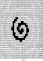
- AFA NV Another type of regularly halftone dots are disclosed in application WO2019/081493 A1 (AGFA NV ) , namely spiral halftone dots which may be implemented with a single threshold tile, such as in AM screening.
- US2008123146 A1 discloses a dither matrix which is used in halftone processing for converting input image data having M input halftone levels into output image data having N (M>N>2) output halftone levels, thus for using a multilevel halftoning process.
- Fig. 10 there are three of said half toning methods implemented in a raster image processor according the type of an image object in a document: a character dithering step for characters; a graphic dithering step for line and graphics and an error diffusion step for images.
- the quality of printing is realized by controlling the halftoning processing in the raster image processor (RIP). But to realize high quality printing on a selected substrate, it is important to use an appropriate threshold tile for halfoning a continuous-tone image (CT).
- CT continuous-tone image
- an operator selects a threshold tile for halftoning on the experience and his own sense depending on the to-be-printed substrate.
- the number of halftone dot shapes and their variances are recently growing as discussed above. When said number halftone dots shapes may be used by said processor, it occurs occasionally that an inappropriate halftone dot shape is selected for halftoning a continuous-tone image (CT) on a selected substrate (S i ). This results that a printed image on the selected substrate is not provided as expected.
- Said processor has several advantages such as providing a threshold selection method for selecting automatically a threshold tile which is appropriate for a selected substrate. Said selection makes it easier for the operator if the number of threshold tiles (TT 1 , TT 2 ,... , TT N ) is large, especially when said threshold tiles determines a large number of halftone dot shapes including variances of said shapes and especially when said shapes including variances influences quality of printing seriously.
- N is hereby larger than 2.
- said processor comprises an input field in which information regarding a substrate, preferably of said plurality of substrates, is to be used; a memory having stored thereon a plurality of threshold tiles (TT 1 , TT 2 ,..., TT N ) for generating regularly tiled halftone dots; and a threshold selector which is capable to select said threshold tile (TT) of said plurality of threshold tiles (TT 1 , TT 2 ,... , TT N ) based on information supplied to the input field.
- the selected threshold tile may be selected for example because it gives less patterns, less/more gloss, less ink usage and/or less shine-through when used for halftoning and representing a continuous-tone image on the selected substrate.
- Said processor manages apparently in-memory-stored plurality of threshold tiles and selects from it the most effective threshold tile for a selected substrate.
- Said processors has also means for receiving the continuous-tone image (CT); and means for storing said continuous-tone image (CT) in another memory.
- CT continuous-tone image
- the regularly tiled halftone dots are preferably arranged according to a screen frequency larger than 100 lines per inch and more preferably according to a screen angle selected from a group consisting of 0°, 7.5°, 15°, 22.5°, 75°, 45°, 67.5° and 82.5°.
- said processor additionally comprises: an ink-usage predictor; and wherein the threshold selector is capable to select the threshold tile (TT) based additionally on predicted amounts of ink from said ink-usage predictor; wherein said amounts are calculated from halftone raster images of the continuous tone image (CT) by threshold tiles of the plurality of threshold tiles (TT 1 , TT 2 ,... , TT N ). Said amount may be described in millilitres but also in ink layer thickness.
- Said ink-usage predictor is capable to predict amount of ink from a selected halftone raster image that shall be printed on a substrate. Said calculation is based on complex mathematics as disclosed further on in an example. The selection of the most effective threshold tile may be the one with the lowest prediction of amount of ink.
- the kind of ink that is used for rendering a continuous-tone image influences also print quality for example inks that have to be cured or inks that have a high penetration in the selected substrate.
- the raster image processor RIP
- the raster image processor preferably further comprises another input field in which information regarding an ink, preferably of said plurality of inks, is to be used; and wherein the threshold selector is capable of determining the threshold tile (TT) based additionally on information supplied to the other input field.
- Said preferred processor manages in-memory-stored plurality of threshold tiles and selects from it the most effective threshold tile for a selected substrate combined with a selected ink.
- said plurality of threshold tiles (TT 1 , TT 2 ,... , TT N ) comprises
- the first path is preferably a space filling curve inside said halftone cell or said first path is a spiral for generating spiral halftone dots.
- Said spiral halftone dots and possible variants are also disclosed in PCT/EP2018/079011 (AGFA NV ).
- the halftone cells of said portion have a quarter section which represents a relative image density which is at least twice the relative image density represented by the halftone cell as a whole, more preferably the portion comprises at least 10% of all the halftone cells having a relative image density of less than 50% or preferably the portion comprises at least 50% of all the halftone cells having a relative image density of less than 50%.
- the portion may comprise at least 4 image clusters.
- the raster image processor is preferably used for halftoning a continuous-tone image (CT) by said processor into a halftone raster image (RT) by a selected threshold tile (TT) from the threshold selector.
- CT continuous-tone image
- RT halftone raster image
- TT selected threshold tile
- Said threshold selector may comprise an ink-usage predictor wherein several threshold tiles of said memory (890) are used for halftoning said continuous-tone image (750) to halftone raster images whereof the ink usage is predicted. The one of the smallest ink-usage is than selected.
- An ink-usage predictor is a tool to predict the amount of ink that shall be used for a halftone raster image (RT) on a selected printing device.
- Said tool is typically a data processing system adapted to predict said amount or a computer program comprising instructions to predict said amount.
- Said computer program is preferably stored on a computer-readable storage medium.
- a continuous-tone image (CT) into a halftone raster image (RT)
- pixels of said raster image are analysed and a certain amount of ink per pixel is determined by said ink-usage predictor.
- the sum of said determined amount of ink per pixel determines the amount of ink that is needed to print one copy of the continuous-tone image on a selected substrate by a printing device.
- an amount per ink is determined for non-image pixels by said ink-usage predictor. This is not automatically zero because ink can flow towards said non-image pixels during or after printing until the ink is fixed on the selected substrate.
- pixels also neighbour pixels from pixels of said raster image (RT) are analysed to predict the flow of ink during or after printing until the ink is fixed on the selected substrate.
- the behaviour of ink flow in non-image pixels and image pixels on a selected substrate is modelled for the present invention by using one or more printing targets comprising a plurality of patches having regular tiled clusters with image-pixels wherein said clusters are mixed with clusters having non-image-pixels. The size and/or shape of said clusters is different between said patches.
- a model By measuring print densities (e.g. by XRITE 500 Series spectro-densitometer) or optical densities, mottle and/or ink layer thickness of printed patches on a selected substrate said model can be calculated for prediction of the amount of ink per pixel in a halftone raster image.
- a model may be calculated because said ink flow (e.g. by absorbance) depends on the substrate parameters such as structure, composition and optical properties.
- optical microscopy e.g. a scanning electron microscopy (SEM)
- SEM scanning electron microscopy
- the ink flow in non-image pixels and image pixels may additional be determined and the presence of ink can be measured.
- the amount of pigments of the used ink for said printed patch may be determined (e.g.
- the model may use said amount of ink for the regular tiled image pixels in said patch for the prediction.
- the ink-usage predictor determines from a pixel if it has some similarity between the pixels of said patches and returns the amount of ink of a patch or a recalculation of if if the similarity matches.
- the amount of pigments of the used ink for a pixel may also be determined to recalculate the amount of ink for said pixel (printed or not printed) by knowing the percentage of pigment in the used ink.
- the ink-usage predictor may use for its model an artificial neural network which is a computing system inspired by biological neural networks that constitute animal brains. More specifically, the predictor is capable of training itself by said artificial neural network to determine the amount of ink that is needed for printing a halftone raster image. By using previous measurements on the printed target, printed patches and/or printed pixels said artificial neural network is trained to accomplish its task on any other halftone raster image, regardless the used threshold tile and continuous tone image, instead of said print target, namely the task to predict the amount of ink that shall be used when printed on a selected substrate.
- a raster image processor is a tool for digital halftoning a continuous tone image (CT) or other file formats including PDF (portable document format), into a halftone raster image (RT) for a printing device.
- Said tool is typically a data processing system adapted to halftone said continuous tone image (CT) or a computer program comprising instructions to digital halftone said continuous tone image (CT).
- Said computer program is preferably stored on a computer-readable storage medium.
- An example of such raster image processor is Harlequin Host Renderer from Global Graphics.
- a raster image processor may convert the halftone raster image (RT) into a format that a printing device such as in inkjet printer can understand.
- said printing device is capable of printing on a plurality of substrates (S 1 , S 2 ,..., S M ); and preferably is capable is of printing with a plurality of inks (I 1 , I 2 ,..., I Q ), such as an offset press.
- the halftone raster image is mostly a well-known raster graphics file format such as TIFF TM (tagged image file format), RTL (raster transfer language) or BMP file format (bitmap).
- TIFF TM tagged image file format
- RTL raster transfer language
- BMP file format bitmap
- the halftone raster image comprises in the present invention regularly tiled halftone dots, generated by using a threshold tile preferably a single threshold tile.
- the generation is done by a screener, also called halftone raster generator, which is part of the raster image processor.
- the halftone raster image produced by the present invention is suitable for rendering a continuous-tone image (CT), i.e. it creates the illusion of a continuous-tone image (CT) on a printed copy.
- CT continuous-tone image
- the screen frequency i.e. the number of halftone cells arranged next to each other per length unit in the direction that yields the greatest value, is above 40 lines per inch (LPI; 15.7 lines/cm), more preferably above 60 LPI (23.6 lines/cm) and most preferably above 100 LPI (39.4 lines/cm). If the screen frequency is below 40 LPI, the halftone dots become visible at viewing distance, also called reading distance, which is about 20 cm.
- Such low screen frequencies are typically used in artistic screening, which is used for decorative purposes such as patterned illustrations, wherein it is intended that the individual dots are visible to the naked eye.
- Halftone raster images wherein the halftone dots are clearly visible at viewing distance are therefore not suitable and shall not be produced by the present invention.
- the above mentioned screen frequency defines the spatial frequency of the halftone cells comprised in the halftone raster image.
- a halftone cell on its turn consists of a grid of pixels and the spatial frequency thereof, called resolution, is expressed as dots per inch (DPI) or pixels per inch (PPI).
- DPI dots per inch
- PPI pixels per inch
- the pixels are also called laser dots and the resolution then refers to the number of laser lines per inch.
- the halftone raster image produced in the method of the present invention has preferably a resolution larger than 600 DPI, more preferably larger than 1200 DPI. Higher resolutions up to 9600 DPI may also be used, e.g. for the printing of security features.
- the halftone raster image used in the method of the present invention is a monochrome image, which may represent a colour selection of a multi-colour printing process, e.g. one of the 4 basic colours in CMYK printing.
- the quality of the printed image is preferably checked with colour density measurement.
- the colour density values can then be used as input parameters of the raster image processor of the present invention.
- Said processor which produces the halftone raster image, adjust said image so that the quality of the printed image is improved in a subsequent press run and/or so that more ink is saved in a subsequent press run.
- the halftone raster image produced by the present invention comprises regularly tiled halftone cells.
- the cells may be tiled along a triangular, rectangular or hexagonal grid and more preferably along a square grid.
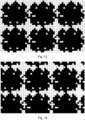
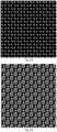
- FIG.13 and FIG.14 each show examples of the preferred embodiment wherein 6 halftone cells are tiled as a square grid.
- the halftone cells themselves also consist of a grid, more particularly a grid of pixels, which may be image pixels or non-image pixels. These pixels preferably have the shape of a regular polygon or convex polygon, e.g. a triangle, a square, a rectangle, a rhombus or a hexagon.
- the Figures show examples of preferred embodiments, wherein the halftone cells consist of a grid of square pixels.
- the halftone raster image comprises halftone cells having more than 2 image clusters, e.g. at least 3 or 4 image clusters, more preferably at least 5 and most preferably at least 6 image clusters.
- FIG. 15 shows three such image clusters: cluster A consists of 7 adjacent image pixels; cluster B consists of 6 adjacent image pixels; and cluster C consists of 5 adjacent image pixels.
- the image pixels d, e and f are in contact with another image pixel but only by a corner of the square; as these pixels are not sharing an edge, they are not considered to be adjacent, as defined above.
- Groups of 4 or less image pixels like group h neither constitute an image cluster in accordance with the above definition.
- FIG. 12 illustrates a further refinement of the definition of an image cluster used herein.
- groups of image pixels in one halftone cell may connect with one or more adjacent edges to another group of image pixels in another halftone cell.
- FIG. 12 shows an example wherein the group of image pixels designated 3a connects to the group designated 3b.
- groups shall not be regarded as separate clusters but together represent a single cluster.
- the halftone cells represented in FIG. 12 each contain only 3 image clusters.
- the image clusters used in the present invention allow to obtain a printed image of the same image density with less ink.
- the large number variances of said halftone dots makes it possible to optimize print quality and/or to minimize ink usage.
- the reasons for this advantage are not completely understood but engineers have systematically measured that press runs according to the method of the present invention consume significantly less ink compared to press runs with plates exposed with a conventional AM screen of the same original image.
- press runs according to the method of the present invention consume significantly less ink compared to press runs with plates exposed with a conventional AM screen of the same original image.
- FM screens consist either of a plurality of single image pixels or a group of four (2x2) image pixels, which degrade more easily than the image clusters used in the present invention.
- the halftone cells having clustered image pixels as described above when compared to a conventional AM halftone dot representing the same relative image density, either absorb a thinner ink film on the ink accepting areas of the plate and/or provide a better spreading of the ink film into the empty (non-image) areas between the image clusters.
- the ink saving effect has been observed with various images and various plates. Ink savings of about 10% were frequently obtained. Ink and paper are the major cost factors of a printer, so even a reduction of the ink consumption by a few percent represents a high cost saving.
- Optimization of the halftone raster image in relation to the substrate that is to be printed e.g. by adjusting the number, size, shape and/or distribution of image clusters in the halftone cells, can lead to even more ink saving, in the range from 10% to 20% compared to conventional AM screening.
- ink provides additional advantages resulting therefrom, e.g. faster drying and/or less energy consumption by drying equipment such as curing units and ovens. Faster drying is particularly beneficial for printing on uncoated plastic foils and in newspaper printing.
- the better spreading of the ink also reduces ink setoff, i.e. the transfer of ink from one printed copy to the back side of another copy lying on top of it, for example in the press delivery tray.
- Shine-through also called print-through, whereby images become visible at the backside of the substrate, e.g. a thin, ink absorbing substrate as used for the printing of newspapers, is reduced as well.
- the method of the present invention is especially advantageous when performed on a perfecting press, i.e. a press that allows the simultaneous printing on both sides of the substrate in one pass through the press.
- the image clusters are not distributed randomly over the halftone cell, but are concentrated locally, so that the image clusters together mimick a conventional AM dot and the method maintains the advantages of AM screens as much as possible.
- the image clusters may be concentrated in e.g. a quarter section of the halftone cell. As a result, that quarter section represents a higher relative image density than the other sections of the halftone cell. More preferably, one quarter section of the halftone cell has a relative image density which is at least twice the relative image density represented by the halftone cell as a whole.
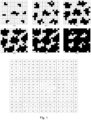
- FIG.5 shows an example of such an arrangement: the 8x8 pixels around the centre of the cell define a quarter section, indicated by thick lines, which has a much higher density of image pixels than the cell as a whole.
- FIG.3 and FIG.4 show different local concentrations of image pixels, which however represent the same halftone image when these cells are tiled next to each other, as shown in FIG. 13 and 14 respectively.
- the halftone raster image generated by the raster image processor from the present invention with a selected threshold tile may contain a combination of different types of halftone cells, e.g. halftone cells with multiple image clusters, as defined above, combined with conventional halftone cells, e.g. AM halftone cells wherein all image pixels are grouped in a single cluster.
- conventional halftone cells e.g. AM halftone cells wherein all image pixels are grouped in a single cluster.
- One or more parts of the image may also be represented by FM screens.
- the highlights and midtones of the image i.e. the subset of all the halftone cells in the image which represent a relative image density of less than 50%, consist entirely of halftone cells having 2 or more image clusters as defined above.
- only a portion of the halftone cells which represent highlights and midtones of the image contain 2 or more image clusters. Said portion may be as low as 5%. Preferably, said portion is at least 10%, more preferably at least 25% and even more preferably at least 50%.
- the substrate on which the halftone raster image may be printed can be of any kind, e.g. plastic films or foils, release liner, textiles, metal, glass, leather, hide, cotton and of course a variety of paper substrates (lightweight, heavyweight, coated, uncoated, paperboard, cardboard, etc.).
- the substrate may be a rigid work piece or a flexible sheet, roll or sleeve.
- Preferred flexible materials include e.g. paper, transparency foils, adhesive PVC sheets, etc., which may have a thickness less than 100 micrometres and preferably less than 50 micrometres.
- Preferred rigid substrates include e.g.
- the substrate may also be a flexible web material (e.g. paper, adhesive vinyl, fabrics, PVC, textile).
- a receiving layer for example an ink-receiving layer, may be applied on the substrate for a good adhesion of the reproduced image on the substrate.
- Print quality on a substrate depends on several factors.
- the print quality becomes better by the selected threshold tile from the present invention. Said several factors are for example:
- the halftone raster image is generated by a threshold tile, preferably a single threshold tile.
- Digital halftoning by means of a threshold tile sometimes also called threshold matrix or threshold array, is known in the art.
- the number of threshold tiles is preferably the same as the number of colour channels in the original continuous-tone image.
- Digital halftoning with a threshold tile typically implies that the original image is sampled into cells which are mapped on the threshold tile.
- the local density value of the original image is then compared with each of the values in the array (if necessary, the density range of the original image is adjusted so that it is equal to the range in the array).
- the dimension of the array i.e. the number of pixels per halftone cell, may depend on various factors such as the resolution of the image setter and the desired quality of the printed image.
- the array is preferably arranged as a square (n x n dimension) or a rectangle (m x n, with m>n).
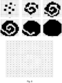
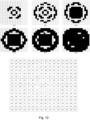
- FIGs.1-16 show examples of square threshold tiles having a dimension of 16x16 locations, wherein each location contains a threshold value in a certain range.
- the threshold value range (1-256) is equal to the number of locations (16x16) in the array; in other embodiments, such as the example shown in FIG. CL16, the value range may be lower than the number of locations and then each individual value may occur at multiple locations of the array.
- the threshold tile is designed in such a way that the number and/or the size of the image clusters increases in line with the corresponding density of the original image.
- FIG.1 shows a cell which represents a relative image density of 25% with 7 image clusters, of which the size grows at increasing image densities.
- FIG.3 shows a 10% cell with 5 image clusters, wherein both the size and the number of clusters grow at higher image densities. While the image density of the halftone cell grows by adding image pixels, it is preferred to keep the non-image pixels together in non-image clusters, which are defined as mutually separated groups of adjacent non-image pixels.
- the ink can spread to a higher extent than when the non-image pixels are isolated or distributed over multiple clusters. In that way, ink can also be saved in the shadow areas of the image.
- the relative image density can be increased by growing the length and/or the thickness of the first spiral (which comprises the image pixels), as shown in FIG.6 , or by inserting image pixels inside the second spiral; or by a combination of any of these methods.
- more image pixels are added to the halftone cell in such a way that the ink channel formed by the second spiral (which comprises the non-image pixels) shrinks and/or becomes thinner, as shown in FIGs. 6 and 9 .
- the plurality of threshold tiles (TT 1 , TT 2 ,..., TT N ) are
- TYPE A and TYPE B a number of variants can be generated but it is found they have to be fine-tuned depending on the selected substrate and/or selected ink. Both types have similar advantages such as resulting in thinner ink layers on the selected substrate.
- a substrate is in the present invention also a substrate-type.
- An ink is in the present invention also an ink-type.
- the first path may be part of a space filling curve in said halftone cell, such as a Hilbert curve or a Peano curve.
- All the clusters which together constitute the first path are preferably mutually connected so that the first path represents a continuous line following said path.
- the first path may also contain isolated non-image pixels or may comprise disconnected clusters, so that the first path is interrupted by empty space at one or more locations.
- the empty space which separates adjacent clusters of the first path may be regarded as protrusions of the second path into the first path. Such protrusions of the second path may cut the first path completely into disconnected clusters, or incompletely whereby the first path is not interrupted but reduced locally to a lower thickness.
- first cluster an arc (200) and/or the first plurality of clusters a plurality of arcs which together represent a first spiral (100) as first path.
- second cluster another arc (201) and/or the second plurality of arcs a plurality of arcs, which together represents a second spiral (101) as second path preferably along said first path.
- Such dots will be referred to herein as "spiral halftone dots".
- the image pixels are represented by the black areas in the figures.
- the non-image pixels define non-printing areas and correspond to the empty space that is left in the dot as represented by the white areas in the figures.
- first spiral as first path is a preferred embodiment but also intersecting paths as first or second path are part of the invention.
- the first and second path may also not a spiral.
- the first path preferably a spiral, grows in length from said feed point (2003, 1003), also called inner end, along said path, preferably spiral-wise, to an outer end (2005, 1005).
- the path preferably a spiral, may overlap with neighbouring halftone dots usually from midtones to shadows ( FIG. 19 ). If said first path is a spiral, the growing is also defined by a start angle for its bending or windings. This is different that AM halftone dots which extends a single cluster to a larger single cluster.
- the number of image pixels per dot is low so that they cannot form a complete winding of the first spiral but just a section thereof, which is referred to as the "first arc".
- the empty space which is partially enclosed by the first arc also may be considered as another arc, which is referred to herein as the "second arc”.
- the number of image pixels per dot is higher so that they can form one or more windings of the "first spiral", thereby also defining a "second spiral" of non-image pixels defined by the empty space between the windings of the first spiral (see e.g. FIG.19 ).
- the shape and size of the printed ink blob is less affected by uncontrolled spreading of the ink because, when the ink blob is pressed onto the substrate, e.g. by a printing press, the excess ink that is printed by the first cluster or first path can flow into the empty space that corresponds to the second cluster or second path. But said spreading depends on substrate and/or ink.
- the empty space defines an ink channel that can accept ink, which is printed from the first cluster/path, thereby providing means for controlling the spreading of the ink.
- the plurality of image clusters within a halftone cell are preferably mutually grouped together within a virtual circle or virtual ellipse or virtual ellipse. Examples are illustrated in Fig. 2 and Fig. 3 wherein the image clusters are positioned within a virtual circle that preferably grows depending on the local density values of a continuous image such as in AM halftone dots.
- a threshold selector is a tool for selecting a threshold tile based on one or more conditions.
- Said tool is typically a data processing system adapted to select a threshold from a plurality of thresholds or a computer program comprising instructions to select said threshold.
- Said computer program is preferably stored on a computer-readable storage medium.
- said of plurality of threshold tiles (TT 1 , TT 2 ,..., TT N ) are stored in a memory and one or more conditions are based on information supplied to the input field in which information regarding substrate is to be used.
- the number of threshold tiles is preferably more than 5, more preferably more than 10.
- the input field from the present invention is preferably part of a graphical user interface (GUI) shown on a computer display such as disclosed in US9058105B2 (International Business Machines Corp ).
- GUI graphical user interface
- An input field is preferably a GUI feature such as a list-box, combo-box and/or an editable text field which gives a RIP-user multiple ways to input or select the desired information.
- the input field may be part of a dialog box from the RIP.
- a prepress workflow system is a tool for managing digital documents, preferably defined in a page description languages (PDL) such as Postscript TM , wherein said documents are prepared for printing on a printing device, such as an offset press.
- PDL page description languages
- Said tool is typically a data processing system adapted to manage and preparing said documents for printing or a computer program comprising instructions to manage and to prepare said documents for printing.
- Said computer program is preferably stored on a computer-readable storage medium.
- An example of such prepress workflow system is Apogee TM from AGFA NV.
- a prepress workflow system comprises a raster image processor from the present invention and further comprises means for transmitting the halftone raster image (RT) to a digital printing press or a plate setter for obtaining a printing plate.
- Said printing plate is preferably a lithographic plate or flexographic plate.
- the printing plates of the present invention are obtained by the exposure of the halftone raster image on a light- or heat-sensitive material called printing plate precursor.
- the plate precursor can be positive or negative working.
- a positive plate precursor has a coating which after exposure and development accepts ink at non-exposed areas and no ink at exposed areas.
- a negative plate accepts ink at exposed areas and no ink at non-exposed areas.
- the image pixels shown in the Figures define ink-accepting areas of the plate and thus correspond to exposed or non-exposed areas of a negative or positive plate precursor respectively.
- the plates of the present invention are preferably lithographic or flexographic printing plates.
- Lithographic plates are typically obtained by exposing the halftone raster image on the light- or heat-sensitive coating of a printing plate precursor by means of a scanning laser, preferably a violet or a near infrared laser, or another digitally modulated light source, such as a digital mirror device, LCD or LED display.
- a lithographic printing plate carrying the halftone raster image of the present invention is obtained.
- That plate can then be mounted on a lithographic printing press, preferably an offset press, wherein ink is supplied to the plate which is then transferred onto the substrate to be printed.
- the exposed precursor can be mounted directly on the press, i.e. without any preceding liquid treatment or other development, and the development of the image may then occur by means of the ink and/or fountain which is supplied to the plate at the start of the press.
- Flexographic plates are generally obtained by UV exposure of a photopolymer coating, typically with a UV lamp through a mask which can be a graphic film in contact with the photopolymer coating or an in-situ mask that is present on top of the photopolymer coating.
- the mask is preferably obtained by exposing the halftone raster image on the film or on the in-situ mask layer by means of a scanning laser, preferably a near infrared layer.
- a data processing system operates one or more computer programs for example a raster image processor.
- the present invention includes such a data processing system that is capable of performing the method of halftoning of the present invention and its preferred embodiments.
- Part or whole of the data processing system and/or the functional units or blocks thereof may be implemented in one or more circuits or circuitry, such as an integrated circuit(s) or as an LSI (large scale integration).
- Each functional unit or block of the data processing system may be individually made into an integrated circuit chip.
- part or whole of the functional units or blocks may be integrated and made into an integrated circuit chip.
- a software program, also called a computer program, which is operated in the data processing system is a program controlling a processor in order to realize functions of the various preferred embodiments according to the present invention. Therefore, information which is handled by the data processing system is temporarily accumulated in a RAM at the time of the processing. Thereafter, the information may be stored in various types of circuitry in the form of ROMs and HDDs, and read out by circuitry within, or included in combination with, the data processing system as necessary, and modification or write-in is performed thereto.
- any one of a semiconductor medium for example, the ROM, a non-volatile memory card or the like
- an optical recording medium for example, a DVD, an MO, an MD, a CD, a BD or the like
- a magnetic recording medium for example, a magnetic tape, a flexible disc or the like
- the functions of the various preferred embodiments of the present invention are not only realized, but the functions of preferred embodiments of the present invention may be realized by processing the loaded software program in combination with an operating system or other application programs, based on an instruction of the program.
- the program can be distributed by being stored in the portable recording medium, or the program can be transmitted to a server computer which is connected through a network such as the Internet.
- a portion of a terminal device, a wireless base station, a host system, or other devices, or the whole thereof may be realized as an LSI which is typically an integrated circuit.
- Each functional unit or block of the data processing system may be individually chipped, or a portion thereof, or the whole thereof may be chipped by being integrated.
- an integrated circuit controller that controls the integrated circuits, is added.
- circuit or circuitry
- circuitry includes combined hardware and software implementations in which the circuit or circuitry is operative to perform functions and operations based on machine readable programs, software or other instructions in any form that are usable to operate the circuit or circuitry.
- the location of the data processing system (18) may be located at a prepress bureau, at the printing device or even at a third party location.
- Digital connections with the data processing system may be made in any form. It can be a connection using an optical fiber or a wireless connection, such as a wifi connection according to the IEEE 802.11 standard.
Landscapes
- Engineering & Computer Science (AREA)
- Multimedia (AREA)
- Signal Processing (AREA)
- General Engineering & Computer Science (AREA)
- Physics & Mathematics (AREA)
- General Physics & Mathematics (AREA)
- Theoretical Computer Science (AREA)
- Image Processing (AREA)
- Facsimile Image Signal Circuits (AREA)
Claims (13)
- Ein Rasterbildprozessor (RIP) für digitale binäre Rasterung eines Halbtonbildes (CT) mittels einer einzelnen Schwellwertkachel (TT) zu einem Rasterbild (RT) für eine Druckvorrichtung, mit der eine Vielzahl von Substraten (S1, S2,..., SM) bedruckt werden kann, wobei der Prozessor Folgendes umfasst:- ein Eingabefeld, in dem Information bezüglich eines Substrats zu verwenden ist,- einen Speicher, in dem eine Vielzahl von Schwellwertkacheln (TT1, TT2,..., TTN) zur Erzeugung regelmäßig gekachelter Rasterpunkte gespeichert ist, wobei die Vielzahl von Schwellwertkacheln zur Rasterung des Halbtonbildes (CT) zu einer Vielzahl von Rasterbildern verwendet wird,- eine Tintenverwendungsvorhersageeinheit, die so konfiguriert ist, dass damit Tintenmengen vorhergesagt werden, die für die Vielzahl von auf dem Substrat zu druckenden Rasterbildern verwendet werden, wobei die vorhergesagten Tintenmengen mittels Schwellwertkacheln der Vielzahl von Schwellwertkacheln (TT1, TT2,..., TTN) aus Rasterbildern des Halbtonbildes (CT) berechnet werden,- einen Schwellwertselektor, mit dem auf Basis von in das Eingabefeld eingeführter Information bezüglich eine Substrats und zusätzlich auf Basis der durch die Tintenverwendungsvorhersageeinheit vorhergesagten Tintenmengen die einzelne Schwellwertkachel (TT) der Vielzahl von Schwellwertkacheln (TT1, TT2,..., TTN) ausgewählt werden kann.
- Der Prozessor (RIP) nach Anspruch 1, wobei mit der Druckvorrichtung eine Vielzahl von Tinten (I1, I2,..., IQ) gedruckt werden kann und wobei der Prozessor ferner ein weiteres Eingabefeld, in dem Information bezüglich einer Tinte zu verwenden ist, umfasst, und wobei mit dem Schwellwertselektor zusätzlich auf Basis von in das weitere Eingabefeld eingefügter Information bezüglich einer Tinte die einzelne Schwellwertkachel (TT) bestimmt werden kann.
- Der Prozessor (RIP) nach Anspruch 2, wobei die regelmäßig gekachelten Rasterpunkte gemäß einer Rasterweite von über 100 Linien pro Zoll angeordnet sind.
- Der Prozessor (RIP) nach Anspruch 3, wobei die regelmäßig gekachelten Rasterpunkte gemäß einer Rasterwinkelung, gewählt aus einer Gruppe bestehend aus 0°, 7,5°, 15°, 22,5°, 75°, 45°, 67,5° und 82,5°, angeordnet sind.
- Der Prozessor (RIP) nach Anspruch 3 oder Anspruch 4, wobei die Vielzahl von Schwellwertkacheln (TT1, TT2,... , TTN) einen Satz von Schwellwertkacheln zur Erzeugung von Rasterbildern umfasst, wobei mindestens ein Teil aller Rasterzellen ein Rasterpunkt ist, umfassend:(i) Bildpixel, die als erster Cluster oder als Vielzahl von Clustern, die gemeinsam eine erste Strecke darstellen, angeordnet sind, und wobei die Bildpixel einen Beginnpunkt (1003, 2003) aufweisen, und(ii) Nicht-Bildpixel, die als zweiter Cluster oder als Vielzahl von Clustern, die gemeinsam eine zweite Strecke darstellen, angeordnet sind.
- Der Prozessor (RIP) nach Anspruch 5, wobei die erste Strecke eine raumfüllende Kurve innerhalb der Rasterzelle ist.
- Der Prozessor (RIP) nach Anspruch 5, wobei die erste Strecke eine Spirale ist.
- Der Prozessor (RIP) nach Anspruch 3 oder Anspruch 4, wobei die Vielzahl von Schwellwertkacheln (TT1, TT2,... , TTN) einen Satz von Schwellwertkacheln zur Erzeugung von Rasterbildern umfasst, wobei mindestens ein Teil aller Rasterzellen mindestens 2 Bildcluster umfasst, wobei Bildcluster als voneinander getrennte Gruppen von mehr als 4 angrenzenden Bildpixeln definiert werden.
- Der Prozessor (RIP) nach Anspruch 8, wobei die Rasterzellen des Teils einen Viertelbereich aufweisen, deren relative Bilddichte bei mindestens zweimal der durch die Rasterzelle als Ganzes dargestellten relativen Bilddichte liegt.
- Der Prozessor (RIP) nach Anspruch 8 oder Anspruch 9, wobei der Teil mindestens 10% aller Rasterzellen mit einer relativen Bilddichte von weniger als 50% umfasst.
- Der Prozessor (RIP) nach Anspruch 8 oder Anspruch 9, wobei der Teil mindestens 4 Bildcluster umfasst.
- Ein Arbeitsablaufsystem für die Druckvorstufe, umfassend einen Rasterbildprozessor nach einem der vorstehenden Ansprüche, wobei das Arbeitsablaufsystem für die Druckvorstufe ferner:- Mittel zur Übertragung des Rasterbildes (RT) zu einer digitalen Druckmaschine oder einem Plattenbelichter zum Erhalten einer Druckplatte umfasst.
- Ein Arbeitsablaufsystem für die Druckvorstufe nach Anspruch 12, wobei die Druckplatte eine lithografische Druckplatte oder eine flexografische Druckplatte ist.
Applications Claiming Priority (2)
| Application Number | Priority Date | Filing Date | Title |
|---|---|---|---|
| EP19171934 | 2019-04-30 | ||
| PCT/EP2020/061846 WO2020221788A1 (en) | 2019-04-30 | 2020-04-29 | Raster image processor |
Publications (2)
| Publication Number | Publication Date |
|---|---|
| EP3963875A1 EP3963875A1 (de) | 2022-03-09 |
| EP3963875B1 true EP3963875B1 (de) | 2025-04-02 |
Family
ID=66379710
Family Applications (1)
| Application Number | Title | Priority Date | Filing Date |
|---|---|---|---|
| EP20721243.2A Active EP3963875B1 (de) | 2019-04-30 | 2020-04-29 | Rasterbildprozessor |
Country Status (4)
| Country | Link |
|---|---|
| US (1) | US20220230031A1 (de) |
| EP (1) | EP3963875B1 (de) |
| CN (1) | CN113711577B (de) |
| WO (1) | WO2020221788A1 (de) |
Families Citing this family (2)
| Publication number | Priority date | Publication date | Assignee | Title |
|---|---|---|---|---|
| WO2022173435A1 (en) * | 2021-02-11 | 2022-08-18 | Hewlett-Packard Development Company, L.P. | Halftone screen tiles |
| US12373661B2 (en) | 2023-12-14 | 2025-07-29 | Ricoh Company, Ltd. | Vectorized interleave of bit planes |
Citations (1)
| Publication number | Priority date | Publication date | Assignee | Title |
|---|---|---|---|---|
| EP3461116A1 (de) * | 2017-09-23 | 2019-03-27 | Heidelberg Polska Sp. z o.o. | Verfahren und system für am-screening und -schutz von druckausgaben |
Family Cites Families (23)
| Publication number | Priority date | Publication date | Assignee | Title |
|---|---|---|---|---|
| AU4237593A (en) * | 1992-05-06 | 1993-11-29 | Microsoft Corporation | Method and system of color halftone reproduction |
| US5579457A (en) * | 1994-07-29 | 1996-11-26 | The Harlequin Group Ltd. | Image display apparatus and method using irregularly placed curving structures |
| US6067406A (en) * | 1995-05-03 | 2000-05-23 | Agfa-Gevaert N.V. | Automatic calibration for output devices based on device output mode |
| US6128099A (en) * | 1995-06-08 | 2000-10-03 | Delabastita; Paul A. | Halftone screen generator, halftone screen and method for generating same |
| JPH0969960A (ja) * | 1995-09-01 | 1997-03-11 | Brother Ind Ltd | 印刷出力装置 |
| US6654143B1 (en) * | 1999-10-28 | 2003-11-25 | Xerox Corporation | Printer characterization adjustment for different papers |
| US7142332B2 (en) * | 2000-12-28 | 2006-11-28 | Xerox Corporation | Method and system of individualizing tone-reproduction curves calibration and applying thereof |
| JP3748209B2 (ja) * | 2001-01-23 | 2006-02-22 | 大日本スクリーン製造株式会社 | 網点面積率測定方法および網点面積率測定装置 |
| US7085014B2 (en) * | 2001-06-06 | 2006-08-01 | International Business Machines Corporation | Method, apparatus and article of manufacture using media roughness as a print parameter |
| US7262881B2 (en) * | 2001-10-15 | 2007-08-28 | Agfa Graphics Nv | Method to determine a characteristic of a printing system |
| JP3848877B2 (ja) * | 2001-12-27 | 2006-11-22 | 三菱重工業株式会社 | 印刷機における色調制御方法とその装置 |
| US8132508B2 (en) | 2005-04-14 | 2012-03-13 | Esko Software Bvba | Method of controlling ink film thickness on a printing plate |
| US20060279788A1 (en) * | 2005-06-10 | 2006-12-14 | Monotype Imaging, Inc. | Automatic generation of supercell halftoning threshold arrays for high addressability devices |
| JP4549333B2 (ja) | 2005-11-01 | 2010-09-22 | 株式会社リコー | ディザマトリクス、画像処理方法、プログラム、画像処理装置、画像形成装置及び画像形成システム |
| JP2009208460A (ja) * | 2007-12-06 | 2009-09-17 | Seiko Epson Corp | 画像処理装置と画像形成装置、および画像形成方法 |
| US8437037B2 (en) * | 2008-05-29 | 2013-05-07 | Xeikon Manufacturing N.V. | Multilevel clustered dot screening method with improved detail and reduced image noise |
| DE102009042374A1 (de) * | 2008-10-20 | 2010-04-22 | Heidelberger Druckmaschinen Ag | Verfahren zur digitalen Rasterung von Halbtonbildern |
| US8399177B2 (en) * | 2008-12-08 | 2013-03-19 | Eastman Kodak Company | Enhanced relief printing plate |
| JP5604761B2 (ja) * | 2009-11-11 | 2014-10-15 | 健治 吉田 | 印刷媒体、情報処理方法、情報処理装置 |
| US9058105B2 (en) | 2010-10-31 | 2015-06-16 | International Business Machines Corporation | Automated adjustment of input configuration |
| PL3701710T3 (pl) | 2017-10-27 | 2023-05-08 | Agfa Offset Bv | Rastrowanie cyfrowe z punktami spiralnymi |
| EP3804290B1 (de) * | 2018-06-05 | 2025-03-26 | Esko Software BV | Druckkalibrierungsprozess und -verfahren und drucksysteme mit konfiguration zum drucken damit |
| CN109086861A (zh) * | 2018-07-26 | 2018-12-25 | 西安理工大学 | 基于bp神经网络的胶印半色调网点预测方法 |
-
2020
- 2020-04-29 US US17/607,177 patent/US20220230031A1/en not_active Abandoned
- 2020-04-29 WO PCT/EP2020/061846 patent/WO2020221788A1/en not_active Ceased
- 2020-04-29 EP EP20721243.2A patent/EP3963875B1/de active Active
- 2020-04-29 CN CN202080032383.4A patent/CN113711577B/zh active Active
Patent Citations (1)
| Publication number | Priority date | Publication date | Assignee | Title |
|---|---|---|---|---|
| EP3461116A1 (de) * | 2017-09-23 | 2019-03-27 | Heidelberg Polska Sp. z o.o. | Verfahren und system für am-screening und -schutz von druckausgaben |
Also Published As
| Publication number | Publication date |
|---|---|
| WO2020221788A1 (en) | 2020-11-05 |
| US20220230031A1 (en) | 2022-07-21 |
| CN113711577A (zh) | 2021-11-26 |
| EP3963875A1 (de) | 2022-03-09 |
| CN113711577B (zh) | 2024-12-24 |
Similar Documents
| Publication | Publication Date | Title |
|---|---|---|
| JP7121357B2 (ja) | スパイラルドットを用いるデジタル階調表現 | |
| EP3963874B1 (de) | Digitale halbtonrasterung mit spiralförmigen punkten | |
| EP3981139B1 (de) | Verfahren zur digitalen rasterung | |
| US20220230031A1 (en) | Raster image processor | |
| EP3834406B1 (de) | Digitale rasterung mit spiralen | |
| CA3080250C (en) | Digital halftoning with spiral dots | |
| JPH10210292A (ja) | 混成ハーフトーンスクリーン生成法 |
Legal Events
| Date | Code | Title | Description |
|---|---|---|---|
| STAA | Information on the status of an ep patent application or granted ep patent |
Free format text: STATUS: UNKNOWN |
|
| STAA | Information on the status of an ep patent application or granted ep patent |
Free format text: STATUS: THE INTERNATIONAL PUBLICATION HAS BEEN MADE |
|
| PUAI | Public reference made under article 153(3) epc to a published international application that has entered the european phase |
Free format text: ORIGINAL CODE: 0009012 |
|
| STAA | Information on the status of an ep patent application or granted ep patent |
Free format text: STATUS: REQUEST FOR EXAMINATION WAS MADE |
|
| 17P | Request for examination filed |
Effective date: 20211130 |
|
| AK | Designated contracting states |
Kind code of ref document: A1 Designated state(s): AL AT BE BG CH CY CZ DE DK EE ES FI FR GB GR HR HU IE IS IT LI LT LU LV MC MK MT NL NO PL PT RO RS SE SI SK SM TR |
|
| DAV | Request for validation of the european patent (deleted) | ||
| DAX | Request for extension of the european patent (deleted) | ||
| STAA | Information on the status of an ep patent application or granted ep patent |
Free format text: STATUS: EXAMINATION IS IN PROGRESS |
|
| 17Q | First examination report despatched |
Effective date: 20230322 |
|
| RAP3 | Party data changed (applicant data changed or rights of an application transferred) |
Owner name: ECO3 BV |
|
| GRAP | Despatch of communication of intention to grant a patent |
Free format text: ORIGINAL CODE: EPIDOSNIGR1 |
|
| STAA | Information on the status of an ep patent application or granted ep patent |
Free format text: STATUS: GRANT OF PATENT IS INTENDED |
|
| INTG | Intention to grant announced |
Effective date: 20241028 |
|
| GRAS | Grant fee paid |
Free format text: ORIGINAL CODE: EPIDOSNIGR3 |
|
| GRAA | (expected) grant |
Free format text: ORIGINAL CODE: 0009210 |
|
| STAA | Information on the status of an ep patent application or granted ep patent |
Free format text: STATUS: THE PATENT HAS BEEN GRANTED |
|
| AK | Designated contracting states |
Kind code of ref document: B1 Designated state(s): AL AT BE BG CH CY CZ DE DK EE ES FI FR GB GR HR HU IE IS IT LI LT LU LV MC MK MT NL NO PL PT RO RS SE SI SK SM TR |
|
| REG | Reference to a national code |
Ref country code: GB Ref legal event code: FG4D |
|
| REG | Reference to a national code |
Ref country code: CH Ref legal event code: EP |
|
| REG | Reference to a national code |
Ref country code: DE Ref legal event code: R096 Ref document number: 602020048693 Country of ref document: DE |
|
| REG | Reference to a national code |
Ref country code: IE Ref legal event code: FG4D |
|
| PGFP | Annual fee paid to national office [announced via postgrant information from national office to epo] |
Ref country code: DE Payment date: 20250422 Year of fee payment: 6 |
|
| PGFP | Annual fee paid to national office [announced via postgrant information from national office to epo] |
Ref country code: GB Payment date: 20250527 Year of fee payment: 6 |
|
| PGFP | Annual fee paid to national office [announced via postgrant information from national office to epo] |
Ref country code: FR Payment date: 20250530 Year of fee payment: 6 |
|
| REG | Reference to a national code |
Ref country code: NL Ref legal event code: MP Effective date: 20250402 |
|
| PG25 | Lapsed in a contracting state [announced via postgrant information from national office to epo] |
Ref country code: NL Free format text: LAPSE BECAUSE OF FAILURE TO SUBMIT A TRANSLATION OF THE DESCRIPTION OR TO PAY THE FEE WITHIN THE PRESCRIBED TIME-LIMIT Effective date: 20250402 |
|
| REG | Reference to a national code |
Ref country code: AT Ref legal event code: MK05 Ref document number: 1782429 Country of ref document: AT Kind code of ref document: T Effective date: 20250402 |
|
| PG25 | Lapsed in a contracting state [announced via postgrant information from national office to epo] |
Ref country code: PT Free format text: LAPSE BECAUSE OF FAILURE TO SUBMIT A TRANSLATION OF THE DESCRIPTION OR TO PAY THE FEE WITHIN THE PRESCRIBED TIME-LIMIT Effective date: 20250804 Ref country code: ES Free format text: LAPSE BECAUSE OF FAILURE TO SUBMIT A TRANSLATION OF THE DESCRIPTION OR TO PAY THE FEE WITHIN THE PRESCRIBED TIME-LIMIT Effective date: 20250402 Ref country code: FI Free format text: LAPSE BECAUSE OF FAILURE TO SUBMIT A TRANSLATION OF THE DESCRIPTION OR TO PAY THE FEE WITHIN THE PRESCRIBED TIME-LIMIT Effective date: 20250402 |
|
| REG | Reference to a national code |
Ref country code: LT Ref legal event code: MG9D |
|
| PG25 | Lapsed in a contracting state [announced via postgrant information from national office to epo] |
Ref country code: NO Free format text: LAPSE BECAUSE OF FAILURE TO SUBMIT A TRANSLATION OF THE DESCRIPTION OR TO PAY THE FEE WITHIN THE PRESCRIBED TIME-LIMIT Effective date: 20250702 Ref country code: GR Free format text: LAPSE BECAUSE OF FAILURE TO SUBMIT A TRANSLATION OF THE DESCRIPTION OR TO PAY THE FEE WITHIN THE PRESCRIBED TIME-LIMIT Effective date: 20250703 |
|
| PG25 | Lapsed in a contracting state [announced via postgrant information from national office to epo] |
Ref country code: PL Free format text: LAPSE BECAUSE OF FAILURE TO SUBMIT A TRANSLATION OF THE DESCRIPTION OR TO PAY THE FEE WITHIN THE PRESCRIBED TIME-LIMIT Effective date: 20250402 |
|
| PG25 | Lapsed in a contracting state [announced via postgrant information from national office to epo] |
Ref country code: BG Free format text: LAPSE BECAUSE OF FAILURE TO SUBMIT A TRANSLATION OF THE DESCRIPTION OR TO PAY THE FEE WITHIN THE PRESCRIBED TIME-LIMIT Effective date: 20250402 |
|
| PG25 | Lapsed in a contracting state [announced via postgrant information from national office to epo] |
Ref country code: HR Free format text: LAPSE BECAUSE OF FAILURE TO SUBMIT A TRANSLATION OF THE DESCRIPTION OR TO PAY THE FEE WITHIN THE PRESCRIBED TIME-LIMIT Effective date: 20250402 |
|
| PG25 | Lapsed in a contracting state [announced via postgrant information from national office to epo] |
Ref country code: AT Free format text: LAPSE BECAUSE OF FAILURE TO SUBMIT A TRANSLATION OF THE DESCRIPTION OR TO PAY THE FEE WITHIN THE PRESCRIBED TIME-LIMIT Effective date: 20250402 |
|
| PG25 | Lapsed in a contracting state [announced via postgrant information from national office to epo] |
Ref country code: RS Free format text: LAPSE BECAUSE OF FAILURE TO SUBMIT A TRANSLATION OF THE DESCRIPTION OR TO PAY THE FEE WITHIN THE PRESCRIBED TIME-LIMIT Effective date: 20250702 |
|
| PG25 | Lapsed in a contracting state [announced via postgrant information from national office to epo] |
Ref country code: IS Free format text: LAPSE BECAUSE OF FAILURE TO SUBMIT A TRANSLATION OF THE DESCRIPTION OR TO PAY THE FEE WITHIN THE PRESCRIBED TIME-LIMIT Effective date: 20250802 |
|
| PG25 | Lapsed in a contracting state [announced via postgrant information from national office to epo] |
Ref country code: LV Free format text: LAPSE BECAUSE OF FAILURE TO SUBMIT A TRANSLATION OF THE DESCRIPTION OR TO PAY THE FEE WITHIN THE PRESCRIBED TIME-LIMIT Effective date: 20250402 |
|
| REG | Reference to a national code |
Ref country code: CH Ref legal event code: H13 Free format text: ST27 STATUS EVENT CODE: U-0-0-H10-H13 (AS PROVIDED BY THE NATIONAL OFFICE) Effective date: 20251125 |
|
| PG25 | Lapsed in a contracting state [announced via postgrant information from national office to epo] |
Ref country code: LU Free format text: LAPSE BECAUSE OF NON-PAYMENT OF DUE FEES Effective date: 20250429 |
|
| REG | Reference to a national code |
Ref country code: BE Ref legal event code: MM Effective date: 20250430 |
|
| REG | Reference to a national code |
Ref country code: DE Ref legal event code: R097 Ref document number: 602020048693 Country of ref document: DE |
|
| PG25 | Lapsed in a contracting state [announced via postgrant information from national office to epo] |
Ref country code: SM Free format text: LAPSE BECAUSE OF FAILURE TO SUBMIT A TRANSLATION OF THE DESCRIPTION OR TO PAY THE FEE WITHIN THE PRESCRIBED TIME-LIMIT Effective date: 20250402 Ref country code: DK Free format text: LAPSE BECAUSE OF FAILURE TO SUBMIT A TRANSLATION OF THE DESCRIPTION OR TO PAY THE FEE WITHIN THE PRESCRIBED TIME-LIMIT Effective date: 20250402 |
|
| PG25 | Lapsed in a contracting state [announced via postgrant information from national office to epo] |
Ref country code: BE Free format text: LAPSE BECAUSE OF NON-PAYMENT OF DUE FEES Effective date: 20250430 |
|
| PG25 | Lapsed in a contracting state [announced via postgrant information from national office to epo] |
Ref country code: CH Free format text: LAPSE BECAUSE OF NON-PAYMENT OF DUE FEES Effective date: 20250430 |
|
| PG25 | Lapsed in a contracting state [announced via postgrant information from national office to epo] |
Ref country code: CZ Free format text: LAPSE BECAUSE OF FAILURE TO SUBMIT A TRANSLATION OF THE DESCRIPTION OR TO PAY THE FEE WITHIN THE PRESCRIBED TIME-LIMIT Effective date: 20250402 |
|
| PG25 | Lapsed in a contracting state [announced via postgrant information from national office to epo] |
Ref country code: EE Free format text: LAPSE BECAUSE OF FAILURE TO SUBMIT A TRANSLATION OF THE DESCRIPTION OR TO PAY THE FEE WITHIN THE PRESCRIBED TIME-LIMIT Effective date: 20250402 |
|
| PG25 | Lapsed in a contracting state [announced via postgrant information from national office to epo] |
Ref country code: SK Free format text: LAPSE BECAUSE OF FAILURE TO SUBMIT A TRANSLATION OF THE DESCRIPTION OR TO PAY THE FEE WITHIN THE PRESCRIBED TIME-LIMIT Effective date: 20250402 Ref country code: RO Free format text: LAPSE BECAUSE OF FAILURE TO SUBMIT A TRANSLATION OF THE DESCRIPTION OR TO PAY THE FEE WITHIN THE PRESCRIBED TIME-LIMIT Effective date: 20250402 |
|
| PG25 | Lapsed in a contracting state [announced via postgrant information from national office to epo] |
Ref country code: IT Free format text: LAPSE BECAUSE OF FAILURE TO SUBMIT A TRANSLATION OF THE DESCRIPTION OR TO PAY THE FEE WITHIN THE PRESCRIBED TIME-LIMIT Effective date: 20250402 |
|
| PG25 | Lapsed in a contracting state [announced via postgrant information from national office to epo] |
Ref country code: MC Free format text: LAPSE BECAUSE OF FAILURE TO SUBMIT A TRANSLATION OF THE DESCRIPTION OR TO PAY THE FEE WITHIN THE PRESCRIBED TIME-LIMIT Effective date: 20250402 |
|
| PLBE | No opposition filed within time limit |
Free format text: ORIGINAL CODE: 0009261 |
|
| STAA | Information on the status of an ep patent application or granted ep patent |
Free format text: STATUS: NO OPPOSITION FILED WITHIN TIME LIMIT |
|
| REG | Reference to a national code |
Ref country code: CH Ref legal event code: L10 Free format text: ST27 STATUS EVENT CODE: U-0-0-L10-L00 (AS PROVIDED BY THE NATIONAL OFFICE) Effective date: 20260211 |
|
| 26N | No opposition filed |
Effective date: 20260105 |
|
| PG25 | Lapsed in a contracting state [announced via postgrant information from national office to epo] |
Ref country code: IE Free format text: LAPSE BECAUSE OF NON-PAYMENT OF DUE FEES Effective date: 20250429 |