EP3963663B1 - Antennenkonstruktion für einen robusten kreuzkopf und kreuzkörperverbindung - Google Patents
Antennenkonstruktion für einen robusten kreuzkopf und kreuzkörperverbindung Download PDFInfo
- Publication number
- EP3963663B1 EP3963663B1 EP20750994.4A EP20750994A EP3963663B1 EP 3963663 B1 EP3963663 B1 EP 3963663B1 EP 20750994 A EP20750994 A EP 20750994A EP 3963663 B1 EP3963663 B1 EP 3963663B1
- Authority
- EP
- European Patent Office
- Prior art keywords
- antenna
- pcb
- antenna radiator
- metal structure
- accessory
- Prior art date
- Legal status (The legal status is an assumption and is not a legal conclusion. Google has not performed a legal analysis and makes no representation as to the accuracy of the status listed.)
- Active
Links
Images

Classifications
-
- H—ELECTRICITY
- H01—ELECTRIC ELEMENTS
- H01Q—ANTENNAS, i.e. RADIO AERIALS
- H01Q1/00—Details of, or arrangements associated with, antennas
- H01Q1/36—Structural form of radiating elements, e.g. cone, spiral, umbrella; Particular materials used therewith
-
- G—PHYSICS
- G06—COMPUTING OR CALCULATING; COUNTING
- G06F—ELECTRIC DIGITAL DATA PROCESSING
- G06F3/00—Input arrangements for transferring data to be processed into a form capable of being handled by the computer; Output arrangements for transferring data from processing unit to output unit, e.g. interface arrangements
- G06F3/01—Input arrangements or combined input and output arrangements for interaction between user and computer
- G06F3/03—Arrangements for converting the position or the displacement of a member into a coded form
- G06F3/041—Digitisers, e.g. for touch screens or touch pads, characterised by the transducing means
-
- G—PHYSICS
- G06—COMPUTING OR CALCULATING; COUNTING
- G06F—ELECTRIC DIGITAL DATA PROCESSING
- G06F3/00—Input arrangements for transferring data to be processed into a form capable of being handled by the computer; Output arrangements for transferring data from processing unit to output unit, e.g. interface arrangements
- G06F3/01—Input arrangements or combined input and output arrangements for interaction between user and computer
- G06F3/03—Arrangements for converting the position or the displacement of a member into a coded form
- G06F3/041—Digitisers, e.g. for touch screens or touch pads, characterised by the transducing means
- G06F3/044—Digitisers, e.g. for touch screens or touch pads, characterised by the transducing means by capacitive means
-
- H—ELECTRICITY
- H01—ELECTRIC ELEMENTS
- H01Q—ANTENNAS, i.e. RADIO AERIALS
- H01Q1/00—Details of, or arrangements associated with, antennas
- H01Q1/27—Adaptation for use in or on movable bodies
- H01Q1/273—Adaptation for carrying or wearing by persons or animals
-
- H—ELECTRICITY
- H01—ELECTRIC ELEMENTS
- H01Q—ANTENNAS, i.e. RADIO AERIALS
- H01Q1/00—Details of, or arrangements associated with, antennas
- H01Q1/36—Structural form of radiating elements, e.g. cone, spiral, umbrella; Particular materials used therewith
- H01Q1/38—Structural form of radiating elements, e.g. cone, spiral, umbrella; Particular materials used therewith formed by a conductive layer on an insulating support
-
- H—ELECTRICITY
- H01—ELECTRIC ELEMENTS
- H01Q—ANTENNAS, i.e. RADIO AERIALS
- H01Q1/00—Details of, or arrangements associated with, antennas
- H01Q1/44—Details of, or arrangements associated with, antennas using equipment having another main function to serve additionally as an antenna, e.g. means for giving an antenna an aesthetic aspect
-
- H—ELECTRICITY
- H01—ELECTRIC ELEMENTS
- H01Q—ANTENNAS, i.e. RADIO AERIALS
- H01Q1/00—Details of, or arrangements associated with, antennas
- H01Q1/50—Structural association of antennas with earthing switches, lead-in devices or lightning protectors
-
- H—ELECTRICITY
- H01—ELECTRIC ELEMENTS
- H01Q—ANTENNAS, i.e. RADIO AERIALS
- H01Q1/00—Details of, or arrangements associated with, antennas
- H01Q1/52—Means for reducing coupling between antennas; Means for reducing coupling between an antenna and another structure
-
- H—ELECTRICITY
- H01—ELECTRIC ELEMENTS
- H01Q—ANTENNAS, i.e. RADIO AERIALS
- H01Q1/00—Details of, or arrangements associated with, antennas
- H01Q1/52—Means for reducing coupling between antennas; Means for reducing coupling between an antenna and another structure
- H01Q1/526—Electromagnetic shields
-
- H—ELECTRICITY
- H01—ELECTRIC ELEMENTS
- H01Q—ANTENNAS, i.e. RADIO AERIALS
- H01Q9/00—Electrically-short antennas having dimensions not more than twice the operating wavelength and consisting of conductive active radiating elements
- H01Q9/04—Resonant antennas
- H01Q9/0407—Substantially flat resonant element parallel to ground plane, e.g. patch antenna
-
- H—ELECTRICITY
- H01—ELECTRIC ELEMENTS
- H01Q—ANTENNAS, i.e. RADIO AERIALS
- H01Q9/00—Electrically-short antennas having dimensions not more than twice the operating wavelength and consisting of conductive active radiating elements
- H01Q9/04—Resonant antennas
- H01Q9/0407—Substantially flat resonant element parallel to ground plane, e.g. patch antenna
- H01Q9/0421—Substantially flat resonant element parallel to ground plane, e.g. patch antenna with a shorting wall or a shorting pin at one end of the element
-
- H—ELECTRICITY
- H04—ELECTRIC COMMUNICATION TECHNIQUE
- H04M—TELEPHONIC COMMUNICATION
- H04M1/00—Substation equipment, e.g. for use by subscribers
- H04M1/72—Mobile telephones; Cordless telephones, i.e. devices for establishing wireless links to base stations without route selection
- H04M1/724—User interfaces specially adapted for cordless or mobile telephones
- H04M1/72403—User interfaces specially adapted for cordless or mobile telephones with means for local support of applications that increase the functionality
- H04M1/72409—User interfaces specially adapted for cordless or mobile telephones with means for local support of applications that increase the functionality by interfacing with external accessories
- H04M1/724094—Interfacing with a device worn on the user's body to provide access to telephonic functionalities, e.g. accepting a call, reading or composing a message
- H04M1/724097—Worn on the head
-
- H—ELECTRICITY
- H01—ELECTRIC ELEMENTS
- H01Q—ANTENNAS, i.e. RADIO AERIALS
- H01Q1/00—Details of, or arrangements associated with, antennas
- H01Q1/48—Earthing means; Earth screens; Counterpoises
-
- H—ELECTRICITY
- H04—ELECTRIC COMMUNICATION TECHNIQUE
- H04R—LOUDSPEAKERS, MICROPHONES, GRAMOPHONE PICK-UPS OR LIKE ACOUSTIC ELECTROMECHANICAL TRANSDUCERS; ELECTRIC HEARING AIDS; PUBLIC ADDRESS SYSTEMS
- H04R1/00—Details of transducers, loudspeakers or microphones
- H04R1/10—Earpieces; Attachments therefor ; Earphones; Monophonic headphones
- H04R1/1041—Mechanical or electronic switches, or control elements
-
- H—ELECTRICITY
- H04—ELECTRIC COMMUNICATION TECHNIQUE
- H04R—LOUDSPEAKERS, MICROPHONES, GRAMOPHONE PICK-UPS OR LIKE ACOUSTIC ELECTROMECHANICAL TRANSDUCERS; ELECTRIC HEARING AIDS; PUBLIC ADDRESS SYSTEMS
- H04R1/00—Details of transducers, loudspeakers or microphones
- H04R1/10—Earpieces; Attachments therefor ; Earphones; Monophonic headphones
- H04R1/1058—Manufacture or assembly
-
- H—ELECTRICITY
- H04—ELECTRIC COMMUNICATION TECHNIQUE
- H04R—LOUDSPEAKERS, MICROPHONES, GRAMOPHONE PICK-UPS OR LIKE ACOUSTIC ELECTROMECHANICAL TRANSDUCERS; ELECTRIC HEARING AIDS; PUBLIC ADDRESS SYSTEMS
- H04R2420/00—Details of connection covered by H04R, not provided for in its groups
- H04R2420/07—Applications of wireless loudspeakers or wireless microphones
Definitions
- Wearable devices or accessories typically have an antenna that connects the accessory to a host device.
- the antenna may also connect one accessory to another, such as when the accessory is a pair of earbuds.
- the accessory may also include a touchpad for receiving inputs, such as commands to increase/decrease the playback volume, skip to the next song, answer a phone call, etc. Due to the typical small form factor of wearable devices, the touchpad and the antenna may compete for space within the wearable and may be positioned within close proximity of one another. In some cases, the design may require more space in the accessory, thereby making the accessory larger than necessary. Large accessories may be cumbersome or unconformable to wear and/or carry.
- Document WO 2018/063506 A1 discloses a multi-function input interface for an electronic device, the multi-function input interface including a conductive portion to transceive a signal through the input interface.
- US 2015/303979 A1 and EP 2 551 955 A2 describe electronic devices including an antenna device with an integrated sensor.
- References EP 3 190 805 A1 and US 2020/091590 A1 relate to communication devices with integrated antennas.
- US 2020/045422 A1 discloses a headset combined with antenna and touch sensor.
- the invention relates to a device, comprising a printed circuit board ("PCB"); and a metal structure configured to be both an antenna and an input control, wherein the metal structure is located at a distance from the PCB and oriented such that the metal structure is substantially parallel to the PCB, wherein the metal structure is coupled to the PCB via at least a first coupling such that metal structure is substantially parallel to the PCB, wherein an electric field extends between the PCB and the metal structure, and the first coupling is an antenna feed and a connection for the input, wherein the device is configured to be worn on a human body, wherein the electric field extends in a direction transverse to a tangent of a longitudinal surface of the human body when the device is being worn on the human body.
- PCB printed circuit board
- the metal structure may be located closer to the at least one second surface of the housing than the at least one first surface of the housing.
- the metal structure may have a central region and a perimeter, wherein the metal structure curves from the central region towards the PCB at the perimeter.
- the input control may be a touchpad.
- the device may be an earbud.
- the technology disclosed may generally relate to wearable devices or accessories that connect to a host device.
- the wearable device may be, for example, one or more earbuds, glasses, virtual reality (VR) headsets, motorcycle helmets, etc.
- Each accessory may have an antenna that connects the accessory to a host device, such as a smart phone.
- the antenna may be located within a housing of the accessory.
- the accessory may also include an input control, such as touchpad or touch input, for receiving user commands.
- the antenna and touchpad may be combined, or integrated, such that the antenna and touchpad are one component within the housing of the accessory.
- the combination antenna and touchpad may be, in some examples, referred to as an antenna radiator.
- the antenna radiator may function as both an antenna and a touchpad as the antenna and the touchpad do not experience cross talk even though they are combined into one element.
- the antenna radiator may be larger within the housing of the accessory than each component would be if they were placed within the housing separately.
- the combination antenna radiator may eliminate the need to create room for two separate components, i.e. the antenna and the touchpad.
- the overall size of the combined antenna and touchpad, or the antenna radiator may be enlarged within the housing as compared to an accessory that has the antenna and touchpad as two separate components.
- the physical size of the antenna and touchpad may be directly correlated to the functional performance of wireless radio and the touch sensor.
- the antenna radiator may, additionally or alternatively, allow for a lower profile of the housing as the housing no longer needs to have room for two separate components.
- the combination antenna radiator may enable both elements, the antenna and touchpad, to be co-located at their most preferred area or location within the device to maximize their respective performance.
- the antenna radiator is coupled to the PCB by one or more contact points.
- One contact functions as both the feed of an antenna as well as the input of touch sensor.
- Other contacts may function as antenna grounding or impedance tuning stub that can be totally isolated from touch sensing functionality.
- the contact points may be one or more spring clips.
- a first spring clip functions as both an antenna feed and a connection for the input control.
- a second spring clip may function as an antenna ground.
- An electromagnetic field may extend or propagate between and/or around the PCB and the antenna radiator.
- the electromagnetic field that propagates around the PCB and the antenna radiator, as opposed to propagating directly between the PCB and the antenna radiator, may allow for enhanced coupling between accessories, such as when the accessory is a pair of earbuds.
- the electric field that propagates around the PCB and the antenna radiator also referred to as the fringe electric field, may allow for better coupling between the accessory and the host device.
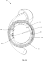
- Figures 1A and 1B illustrate different perspective views of an antenna radiator within a housing of an accessory 100.
- an accessory may be used to refer to any electronic device that is coupled to a host device or another accessory and is capable of receiving inputs from a user. Examples of accessories may include earbuds, smartwatches, headsets, other wearable electronics, etc. Accessories may further include other electronic devices, such as a laptop, hub, tablet, etc.
- the accessory 100 shown in Figures 1A and 1B is an earbud, however, this is merely one example and is not intended to be limiting.
- Accessory 100 may include a housing 102, a PCB 104, an antenna radiator 106, and spring clips 108, 110.
- the antenna radiator 106 may be a combined antenna and touchpad. Thus, the antenna radiator 106 may function as both the antenna and the touchpad.
- Accessory 100 may include additional components, such as one or more processors (e.g., a central processing unit (CPU)), memory (e.g., RAM and internal hard drives) storing data and instructions, a display (e.g., a monitor having a screen, a touchscreen, or other devices such as a smartwatch display that is operable to display information), and user input devices (e.g., a keyboard, touchscreen or microphone).
- processors e.g., a central processing unit (CPU)
- memory e.g., RAM and internal hard drives
- a display e.g., a monitor having a screen, a touchscreen, or other devices such as a smartwatch display that is operable to display information
- Housing 102 may be shaped to be worn on a human body. For example, at least one first surface of the housing may be shaped to come in contact with the body and at least one second surface of the housing may be shaped to be exposed when the accessory 100 is worn on the body. The first surface and the second surface may be opposite each other. Housing 102 may house the internal components of accessory 100. For example, within housing 102 may be PCB 104, the antenna radiator 106, spring clips 108, 110, and any additional components, as described above. As shown, a portion of housing 102 is removed such that the internal components of the accessory 100 may be visible.
- PCB 104 may be located within housing 102. In some examples, PCB 104 may be located closer to the first surface than the second surface of housing 102. That is, PCB 104 may be located closer to the human body when accessory 100 is being worn as compared to other components.
- antenna radiator 106 is important as the human body is a dielectric such that the human body may degrade, or weaken, the functioning of antenna components.
- the antenna radiator 106 may be located within housing 102 between PCB 104 and the second surface of housing 102. That is, the antenna radiator 106 may be located closer to the second surface of housing 102, i.e. the exposed surface of housing 102 when accessory 100 is worn on the body.
- the PCB 104 may shield, or isolate, the antenna radiator 106 from the body such that the antenna radiator 106 experiences less loss effect from the body.
- the antenna radiator 106 may make the antenna radiator 106.
- the antenna and touchpad function more efficiently and less susceptible to wearing conditions, as compared to accessories that have antennas along the perimeter of the housing or those susceptible to placement on the human body.
- antenna radiator 106 may be located centrally within the housing 102 such that antenna radiator 106 may not come in contact with the human body.
- antenna radiator 106 and, therefore, the antenna and touchpad may have a maximum amount of clearance from the user's body within the given volume defined by the housing 102 of the device 100.
- the location of antenna radiator 106 may reduce the dieletric loading effect from the human body and, therefore, may reduce variability due to wearing tolerance and rotation of the accessory.
- antenna radiator 106 may by a solid structure having a circular shape.
- the structure may be a metal structure.
- the shape of the antenna radiator may change based on the shape of the accessory 100 and/or housing 102.
- antenna radiator 106 may have a square, rectangular, oblong, etc. shape and having a circular shape, as shown, is merely one example and is not intended to be limiting.
- antenna radiator 106 may have portions of the structure cut out.
- the cut outs may create a pattern in antenna radiator 106. This may create a lighter and/or less expensive antenna radiator 106 without compromising the performance of the antenna radiator 106.
- the antenna pattern on antenna radiator 106 may be made in a meshed form. The meshed form may reduce the touch capacitance of the antenna radiator 106 without sacrificing or reducing the antenna radiation performance.
- Antenna radiator 106 may have a curvature.
- antenna radiator may have a central region 112 and a perimeter 114.
- the antenna radiator 106 may curve from the central region 112 towards the PCB 104 at the perimeter.
- the curvature of the antenna radiator 106 may be convex.
- the curvature of antenna radiator 106 may correspond to or substantially follow the curvature of housing 102 of the accessory 100.
- the antenna radiator 106 may not curve or the antenna radiator 106 may have a concave curvature.
- the antenna radiator 106 may be sized such that the perimeter 114 of the antenna radiator 106 is located at a distance from housing 102. That is, antenna radiator 106 may have a size that is smaller than the opening in housing 102 in which the antenna radiator 106 is placed. The size of antenna radiator 106 may reduce false touch by pulling away from the housing 102 of the accessory 100. Additionally or alternatively, the size of antenna radiator 106 may provide minimal, if any, additional protrusion from housing 102. In some examples, the size of antenna radiator 106 may lower the susceptibility to finger gesture of inputs, such as pause, play, etc.
- the antenna radiator 106 may be coupled to the PCB 104 via at least one contact point, such as a spring clip110. According to some examples not covered by the appended claims, there may be two contact points, such as first and second spring clips 108, 110. Thus, the radio-frequency ("RF") circuitry to the antenna and the touch sensor circuitry for the touchpad may both be connected to the antenna radiator 106. This may allow the antenna and touchpad to work independently without having their respective signals cross talking. For example, the antenna RF signal may not impact or interfere with the touch sensor signals and vice versa.
- the antenna radiator 106 may be coupled to the PCB 104 such that antenna radiator 106 is substantially parallel to the PCB.
- a first spring clip 110- may function as both an antenna feed and an input for a touch sensor.
- the device 100 may include decoupling circuitry to be implemented at spring clip 110 in order to make both the radio system and touch sensor system function properly and independently while sharing the same metal structure 106. Combining the antenna feed with the circuitry for receiving the signal for an input into one spring clip 110, may increase the efficiency of the accessory 100. Moreover, overall manufacturing costs may be reduced as one component, spring clip 108, may have two functions, being the antenna ground and being the circuitry for receiving signals indicating a touch input.
- a second spring clip 108 may function as an antenna ground pin or impedance tuning sub. A capacitor with calculated capacitance value may be implemented on spring clip 108 to prevent touch input signal being shorted to ground.
- Figure 2 illustrates an example of an electric field extending between the PCB and the antenna radiator.
- the electric field 220 may extend between PCB 204 and antenna radiator 206.
- the portion of the electric field that remains between PCB 204 and antenna radiator 206 may be the vertical electric field 224 and the portion of the electric field 220 that extends beyond or outside of the PCB 204 and antenna radiator 206 may be the fringe electric field 222.
- the antenna radiator described herein may reduce the electromagnetic field concentration as compared to a traditional monopole antenna.
- the antenna's opening carries the strongest electric field of an antenna which is responsible for radiation.
- the antenna's opening of the planar antenna radiator described herein may be wider than the antenna's opening for traditional monopole antenna. This may smooth out the concentration of the electric field of an antenna, and, therefore, help reduce the variation due to the loading effects from the human body tissues, which may be high permittivity materials.
- the vertical electric field 224 may extend between PCB 204 and antenna radiator 206.
- the vertical electric field 224 may maximize the surface wave that propagates along the surface of antenna radiator 206. As the surface wave is maximized, the sensitivity for cross-head and cross-body linkage may increase.
- Cross-head linkage may occur between two earbuds, such as a right and left earbud.
- Cross-body linkage may occur between a left and/or right earbud and a host device, such as a smartphone.
- the vertical electric field 224 may not be vertical when the accessory is in use.
- the vertical electric field 224 is perpendicular to the tangential vertical surface of the human body.
- the vertical electric field 224 is perpendicular to the tangential vertical surface of the user's ear or cheek.
- the vertical electric field 224 may be horizontal, or at any other angle, when the accessory is being worn.
- the fringe electric field 222 may propagate and/or radiate outwardly from the edge of PCB 204 to the edge of antenna radiator 206. As the fringe electric field 222 radiates from the PCB 204 to the antenna radiator 206, the strength of the fringe electric field 222 may decrease as the distance away from the PCB 204 and the antenna radiator 206 increases.
- the fringe electric field 22 may allow for connectivity and/or increased connectivity between accessories and/or between an accessory and a host device. For example, when the accessory is a pair of earbuds, the fringe electric field 222 from the right earbud may propagate around the user's head and be used to connect the right earbud to the left earbud.
- the fringe electric field 222 from the left earbud may propagate around the user's head and be used to connect the left earbud to the right earbud.
- the fringe electric field 222 from the accessory may propagate and be used to connect the accessory to the host device.
- the fringe electric field 222 from a pair of earbuds may propagate around the user and be used to connect to the host device, which may be a smartphone in the user's hands.
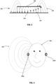
- Figure 3 illustrates an example of the fringe electric field propagating around a user's head.
- the user 330 may be wearing a right and left earbud 300a, 300b.
- the fringe electric field 322 of the right earbud 300a may propagate around right earbud 300a and user 330.
- the left earbud 300b may have a fringe electric field propagating around left earbud 300b and user 330.
- the propagation of fringe electric field 322 may increase the connectivity between the right earbud 300a and left earbud 300b and/or between the right earbud 300a and the host device (not shown).
- the propagation of the fringe electric field 322 around the human body and/or across the human body may be stronger at locations further away from the accessory than an electric field from a monopole antenna.
- the increased strength of the fringe electric field 322 may increase the connectivity for cross-head linkage between right earbud 300a and left earbud 300b as well as for cross-body linkage between right earbud 300a and a host device (not shown).
- the size, shape, and placement of the antenna radiator described herein may provide the user a better experience when interacting with the accessory housing the antenna radiator.
- the overall size of the accessory may decrease and/or there may be few protrusions extending from the accessory as there only needs to be room for one component instead of two.
- the antenna radiator allows for the size of the antenna and touchpad to be increased within the housing of the device.
- combining the function of the antenna and the touchpad into one element may allow both components to co-locate at their best performance benefitting location. This may improve antenna efficiency by having an increased antenna aperture and/or volume.
- the placement of the antenna radiator within the housing of the accessory may reduce the frequency loading effect from the user's body. Moreover, the internal placement of the antenna radiator may reduce the likelihood of the antenna radiator from coming in contact with the human body which may prevent the human body from weakening the antenna components.
Landscapes
- Engineering & Computer Science (AREA)
- General Engineering & Computer Science (AREA)
- Theoretical Computer Science (AREA)
- Human Computer Interaction (AREA)
- Physics & Mathematics (AREA)
- General Physics & Mathematics (AREA)
- Computer Networks & Wireless Communication (AREA)
- Signal Processing (AREA)
- Electromagnetism (AREA)
- Support Of Aerials (AREA)
Claims (7)
- Vorrichtung (100), umfassend:einer Leiterplatte, PCB, (104, 204); undeine Metallstruktur (106, 206), die konfiguriert ist, um sowohl eine Antenne als auch eine Eingabesteuerung zu sein,wobei die Metallstruktur (106, 206) sich in einem Abstand von der PCB (104, 204) befindet und ausgerichtet ist, sodass die Metallstruktur (106, 206) im Wesentlichen parallel zu der PCB (104, 204) ist,wobei die Metallstruktur (106, 206) an die PCB (104, 204) über zumindest eine erste Kopplung (110) gekoppelt ist, sodass die Metallstruktur (106, 206) im Wesentlichen parallel zu der PCB (104, 204) ist,wobei ein elektrisches Feld (224) konfiguriert ist, um sich zwischen der PCB (104, 204) und der Metallstruktur (106, 206) zu erstrecken,wobei die erste Kopplung (110) eine Antennenzuleitung und ein Anschluss für die Eingabesteuerung ist,und wobei die Vorrichtung (100) konfiguriert ist, um an einem menschlichen Körper getragen zu werden, dadurch gekennzeichnet,dass das elektrische Feld (224) sich in einer Richtung quer zu einer Tangente einer Längsfläche des menschlichen Körpers erstreckt, wenn die Vorrichtung (100) an dem menschlichen Körper getragen wird.
- Vorrichtung nach Anspruch 1, ferner umfassend eine zweite Kopplung (108), die konfiguriert ist, um ein Antennenstift oder ein Impedanzabstimmungsstutzen zu sein.
- Vorrichtung nach Anspruch 1, wobei die Metallstruktur (106, 206) eine zentrale Region (112) und einen Umfang (114) aufweist, wobei die Metallstruktur (106, 206) sich an dem Umfang (114) von der zentralen Region (112) zu der PCB (104, 204) hin wölbt.
- Vorrichtung nach Anspruch 1, wobei die Eingabesteuerung ein Touchpad ist.
- Vorrichtung nach Anspruch 1, wobei die PCB (104, 204) konfiguriert ist, um die Metallstruktur (106, 206) von dem menschlichen Körper abzuschirmen.
- Vorrichtung nach Anspruch 1, wobei das elektrische Feld (224) konfiguriert ist, um sich um den menschlichen Körper herum auszubreiten.
- Vorrichtung nach Anspruch 1, wobei, wenn die Metallstruktur (106, 206) eine Eingabe empfängt, die Metallstruktur (106, 206) konfiguriert ist, um eine Änderung der Kapazität zu erfassen.
Applications Claiming Priority (1)
| Application Number | Priority Date | Filing Date | Title |
|---|---|---|---|
| PCT/US2020/042094 WO2022015298A1 (en) | 2020-07-15 | 2020-07-15 | Antenna design for robust cross-head and cross-body link |
Publications (2)
| Publication Number | Publication Date |
|---|---|
| EP3963663A1 EP3963663A1 (de) | 2022-03-09 |
| EP3963663B1 true EP3963663B1 (de) | 2024-10-02 |
Family
ID=71944388
Family Applications (1)
| Application Number | Title | Priority Date | Filing Date |
|---|---|---|---|
| EP20750994.4A Active EP3963663B1 (de) | 2020-07-15 | 2020-07-15 | Antennenkonstruktion für einen robusten kreuzkopf und kreuzkörperverbindung |
Country Status (4)
| Country | Link |
|---|---|
| US (2) | US12068530B2 (de) |
| EP (1) | EP3963663B1 (de) |
| CN (1) | CN114207939B (de) |
| WO (1) | WO2022015298A1 (de) |
Families Citing this family (2)
| Publication number | Priority date | Publication date | Assignee | Title |
|---|---|---|---|---|
| KR102894642B1 (ko) * | 2021-04-13 | 2025-12-03 | 삼성전자주식회사 | 안테나를 포함하는 전자 장치 |
| CN114679650A (zh) * | 2022-03-24 | 2022-06-28 | 东莞泰升音响科技有限公司 | 一种低sar值天线结构的tws耳机 |
Citations (3)
| Publication number | Priority date | Publication date | Assignee | Title |
|---|---|---|---|---|
| EP2551955A2 (de) * | 2011-07-27 | 2013-01-30 | Samsung Electronics Co., Ltd. | Integrierte Antenne und Sensorelementvorrichtung für ein tragbares drahtloses Endgerät |
| US20200045422A1 (en) * | 2018-08-02 | 2020-02-06 | Holy Stone Enterprise Co., Ltd. | Bluetooth headset combined with antenna and touch sensor |
| EP3772858A1 (de) * | 2019-08-09 | 2021-02-10 | Panasonic Intellectual Property Management Co., Ltd. | Drahtloser ohrhörer |
Family Cites Families (17)
| Publication number | Priority date | Publication date | Assignee | Title |
|---|---|---|---|---|
| US8482488B2 (en) * | 2004-12-22 | 2013-07-09 | Oakley, Inc. | Data input management system for wearable electronically enabled interface |
| US8018983B2 (en) | 2007-01-09 | 2011-09-13 | Sky Cross, Inc. | Tunable diversity antenna for use with frequency hopping communications protocol |
| US7724201B2 (en) | 2008-02-15 | 2010-05-25 | Sierra Wireless, Inc. | Compact diversity antenna system |
| JP2011002947A (ja) | 2009-06-17 | 2011-01-06 | Alps Electric Co Ltd | アンテナ付タッチパッド入力装置、及び該装置を搭載した電子機器 |
| US9184502B2 (en) | 2010-12-22 | 2015-11-10 | Intel Corporation | Antenna integrated into a touch sensor of a touchscreen display |
| US20120329524A1 (en) * | 2011-06-22 | 2012-12-27 | Kent Joel C | Touch sensor and antenna integration along an electronic device housing |
| EP2835863B1 (de) * | 2013-08-09 | 2019-12-11 | Oticon A/s | Hörgerät mit RF-Antenne |
| KR102139145B1 (ko) | 2014-04-22 | 2020-07-29 | 삼성전자주식회사 | 센서 겸용 안테나 장치를 갖는 전자 장치 |
| JP6475998B2 (ja) | 2015-02-10 | 2019-02-27 | デクセリアルズ株式会社 | タッチパッド用アンテナ装置、及び電子機器 |
| DK3148219T3 (da) * | 2015-09-28 | 2021-01-25 | Oticon As | Høreanordning |
| US20170195466A1 (en) | 2016-01-02 | 2017-07-06 | Erato (Cayman) Holdings Co., Ltd. | Radiofrequency communication device |
| US11366431B2 (en) | 2016-09-29 | 2022-06-21 | Intel Corporation | Multi-function antenna and input interface |
| US10129165B2 (en) | 2017-02-28 | 2018-11-13 | Apple Inc. | Electronics devices having antenna diversity capabilities |
| EP3422473B1 (de) | 2017-06-30 | 2021-07-28 | GN Audio A/S | Antennenstruktur für ein headset |
| CN208273204U (zh) | 2018-06-22 | 2018-12-21 | 歌尔科技有限公司 | 耳机 |
| US11522273B2 (en) | 2018-09-13 | 2022-12-06 | Google Llc | Antenna for wearable devices |
| CN109547885A (zh) | 2018-11-29 | 2019-03-29 | 北京羽扇智信息科技有限公司 | 一种无线通信耳机 |
-
2020
- 2020-07-15 WO PCT/US2020/042094 patent/WO2022015298A1/en not_active Ceased
- 2020-07-15 CN CN202080008763.4A patent/CN114207939B/zh active Active
- 2020-07-15 US US17/419,877 patent/US12068530B2/en active Active
- 2020-07-15 EP EP20750994.4A patent/EP3963663B1/de active Active
-
2024
- 2024-07-18 US US18/777,338 patent/US20240372249A1/en active Pending
Patent Citations (3)
| Publication number | Priority date | Publication date | Assignee | Title |
|---|---|---|---|---|
| EP2551955A2 (de) * | 2011-07-27 | 2013-01-30 | Samsung Electronics Co., Ltd. | Integrierte Antenne und Sensorelementvorrichtung für ein tragbares drahtloses Endgerät |
| US20200045422A1 (en) * | 2018-08-02 | 2020-02-06 | Holy Stone Enterprise Co., Ltd. | Bluetooth headset combined with antenna and touch sensor |
| EP3772858A1 (de) * | 2019-08-09 | 2021-02-10 | Panasonic Intellectual Property Management Co., Ltd. | Drahtloser ohrhörer |
Also Published As
| Publication number | Publication date |
|---|---|
| US20240372249A1 (en) | 2024-11-07 |
| WO2022015298A1 (en) | 2022-01-20 |
| CN114207939A (zh) | 2022-03-18 |
| US20220181769A1 (en) | 2022-06-09 |
| CN114207939B (zh) | 2025-04-25 |
| US12068530B2 (en) | 2024-08-20 |
| EP3963663A1 (de) | 2022-03-09 |
Similar Documents
| Publication | Publication Date | Title |
|---|---|---|
| US20240372249A1 (en) | Antenna Design for Robust Cross-head and Cross-body Link | |
| EP3910918B1 (de) | Antenne und elektronische vorrichtung damit | |
| EP3608751B1 (de) | Faltbare elektronische vorrichtung mit antenne integriert im gehäuserahmen | |
| CN102646861B (zh) | 具有基于邻近度射频功率控制的集成邻近度传感器的天线 | |
| CA2767776C (en) | Electronic devices with capacitive proximity sensors for proximity-based radio-frequency power control | |
| EP2276108B1 (de) | Elektronische Vorrichtungen mit Sekundärstrahler-Resonanzelementen zur Reduzierung der Nahfeldstrahlung | |
| US11736844B2 (en) | Earphone module | |
| CN112534640B (zh) | 用于可穿戴装置的天线 | |
| KR102419622B1 (ko) | 적어도 하나의 지정된 대역 상의 노이즈를 차단하기 위한 구조체 및 그것을 포함하는 전자 장치 | |
| US20120329524A1 (en) | Touch sensor and antenna integration along an electronic device housing | |
| CN209929474U (zh) | 一种天线结构及耳机 | |
| US20230110601A1 (en) | Antenna and electronic device including same | |
| AU2014202603B2 (en) | Electronic devices with capacitive proximity sensors for proximity-based radio-frequency power control | |
| CN115441179A (zh) | 传感器及天线组件、无线耳机 | |
| CN220527205U (zh) | 天线及电子设备 | |
| TWI849470B (zh) | 無線電子裝置之天線電路及其操作方法 | |
| KR20220033045A (ko) | 접근 검출 장치 및 전자장치 | |
| CN223052373U (zh) | 天线组件及可穿戴设备 | |
| CN116260478A (zh) | 无线电子装置的天线电路及其操作方法 | |
| CN121709929A (zh) | 天线组件及可穿戴设备 | |
| TW202418654A (zh) | 用於筆記型電腦的切換式環天線模組 | |
| CN121336156A (zh) | 包括刚柔结合印刷电路板的可穿戴电子装置 | |
| TW201304280A (zh) | 具電波干擾遮蔽蓋之天線 | |
| HK1153310B (en) | Electronic devices with capacitive proximity sensors |
Legal Events
| Date | Code | Title | Description |
|---|---|---|---|
| STAA | Information on the status of an ep patent application or granted ep patent |
Free format text: STATUS: UNKNOWN |
|
| STAA | Information on the status of an ep patent application or granted ep patent |
Free format text: STATUS: THE INTERNATIONAL PUBLICATION HAS BEEN MADE |
|
| PUAI | Public reference made under article 153(3) epc to a published international application that has entered the european phase |
Free format text: ORIGINAL CODE: 0009012 |
|
| STAA | Information on the status of an ep patent application or granted ep patent |
Free format text: STATUS: REQUEST FOR EXAMINATION WAS MADE |
|
| 17P | Request for examination filed |
Effective date: 20210713 |
|
| AK | Designated contracting states |
Kind code of ref document: A1 Designated state(s): AL AT BE BG CH CY CZ DE DK EE ES FI FR GB GR HR HU IE IS IT LI LT LU LV MC MK MT NL NO PL PT RO RS SE SI SK SM TR |
|
| STAA | Information on the status of an ep patent application or granted ep patent |
Free format text: STATUS: EXAMINATION IS IN PROGRESS |
|
| 17Q | First examination report despatched |
Effective date: 20230124 |
|
| DAV | Request for validation of the european patent (deleted) | ||
| DAX | Request for extension of the european patent (deleted) | ||
| REG | Reference to a national code |
Ref country code: DE Ref legal event code: R079 Free format text: PREVIOUS MAIN CLASS: H01Q0001270000 Ipc: H01Q0009040000 Ref country code: DE Ref legal event code: R079 Ref document number: 602020038708 Country of ref document: DE Free format text: PREVIOUS MAIN CLASS: H01Q0001270000 Ipc: H01Q0009040000 |
|
| GRAP | Despatch of communication of intention to grant a patent |
Free format text: ORIGINAL CODE: EPIDOSNIGR1 |
|
| STAA | Information on the status of an ep patent application or granted ep patent |
Free format text: STATUS: GRANT OF PATENT IS INTENDED |
|
| RIC1 | Information provided on ipc code assigned before grant |
Ipc: H04R 1/10 20060101ALN20240328BHEP Ipc: H01Q 1/48 20060101ALN20240328BHEP Ipc: H01Q 1/52 20060101ALI20240328BHEP Ipc: H01Q 1/44 20060101ALI20240328BHEP Ipc: H01Q 1/27 20060101ALI20240328BHEP Ipc: H01Q 9/04 20060101AFI20240328BHEP |
|
| INTG | Intention to grant announced |
Effective date: 20240422 |
|
| RIN1 | Information on inventor provided before grant (corrected) |
Inventor name: ZHU, JIANG Inventor name: ASRANI, VIJAY Inventor name: XU, NAN |
|
| GRAS | Grant fee paid |
Free format text: ORIGINAL CODE: EPIDOSNIGR3 |
|
| GRAA | (expected) grant |
Free format text: ORIGINAL CODE: 0009210 |
|
| STAA | Information on the status of an ep patent application or granted ep patent |
Free format text: STATUS: THE PATENT HAS BEEN GRANTED |
|
| AK | Designated contracting states |
Kind code of ref document: B1 Designated state(s): AL AT BE BG CH CY CZ DE DK EE ES FI FR GB GR HR HU IE IS IT LI LT LU LV MC MK MT NL NO PL PT RO RS SE SI SK SM TR |
|
| P01 | Opt-out of the competence of the unified patent court (upc) registered |
Free format text: CASE NUMBER: APP_48304/2024 Effective date: 20240822 |
|
| REG | Reference to a national code |
Ref country code: GB Ref legal event code: FG4D |
|
| REG | Reference to a national code |
Ref country code: CH Ref legal event code: EP |
|
| REG | Reference to a national code |
Ref country code: DE Ref legal event code: R096 Ref document number: 602020038708 Country of ref document: DE |
|
| REG | Reference to a national code |
Ref country code: IE Ref legal event code: FG4D |
|
| REG | Reference to a national code |
Ref country code: NL Ref legal event code: FP |
|
| REG | Reference to a national code |
Ref country code: LT Ref legal event code: MG9D |
|
| REG | Reference to a national code |
Ref country code: AT Ref legal event code: MK05 Ref document number: 1729144 Country of ref document: AT Kind code of ref document: T Effective date: 20241002 |
|
| PG25 | Lapsed in a contracting state [announced via postgrant information from national office to epo] |
Ref country code: HR Free format text: LAPSE BECAUSE OF FAILURE TO SUBMIT A TRANSLATION OF THE DESCRIPTION OR TO PAY THE FEE WITHIN THE PRESCRIBED TIME-LIMIT Effective date: 20241002 Ref country code: IS Free format text: LAPSE BECAUSE OF FAILURE TO SUBMIT A TRANSLATION OF THE DESCRIPTION OR TO PAY THE FEE WITHIN THE PRESCRIBED TIME-LIMIT Effective date: 20250202 Ref country code: PT Free format text: LAPSE BECAUSE OF FAILURE TO SUBMIT A TRANSLATION OF THE DESCRIPTION OR TO PAY THE FEE WITHIN THE PRESCRIBED TIME-LIMIT Effective date: 20250203 |
|
| PG25 | Lapsed in a contracting state [announced via postgrant information from national office to epo] |
Ref country code: FI Free format text: LAPSE BECAUSE OF FAILURE TO SUBMIT A TRANSLATION OF THE DESCRIPTION OR TO PAY THE FEE WITHIN THE PRESCRIBED TIME-LIMIT Effective date: 20241002 |
|
| PG25 | Lapsed in a contracting state [announced via postgrant information from national office to epo] |
Ref country code: BG Free format text: LAPSE BECAUSE OF FAILURE TO SUBMIT A TRANSLATION OF THE DESCRIPTION OR TO PAY THE FEE WITHIN THE PRESCRIBED TIME-LIMIT Effective date: 20241002 |
|
| PG25 | Lapsed in a contracting state [announced via postgrant information from national office to epo] |
Ref country code: ES Free format text: LAPSE BECAUSE OF FAILURE TO SUBMIT A TRANSLATION OF THE DESCRIPTION OR TO PAY THE FEE WITHIN THE PRESCRIBED TIME-LIMIT Effective date: 20241002 |
|
| PG25 | Lapsed in a contracting state [announced via postgrant information from national office to epo] |
Ref country code: NO Free format text: LAPSE BECAUSE OF FAILURE TO SUBMIT A TRANSLATION OF THE DESCRIPTION OR TO PAY THE FEE WITHIN THE PRESCRIBED TIME-LIMIT Effective date: 20250102 |
|
| PG25 | Lapsed in a contracting state [announced via postgrant information from national office to epo] |
Ref country code: GR Free format text: LAPSE BECAUSE OF FAILURE TO SUBMIT A TRANSLATION OF THE DESCRIPTION OR TO PAY THE FEE WITHIN THE PRESCRIBED TIME-LIMIT Effective date: 20250103 Ref country code: LV Free format text: LAPSE BECAUSE OF FAILURE TO SUBMIT A TRANSLATION OF THE DESCRIPTION OR TO PAY THE FEE WITHIN THE PRESCRIBED TIME-LIMIT Effective date: 20241002 Ref country code: AT Free format text: LAPSE BECAUSE OF FAILURE TO SUBMIT A TRANSLATION OF THE DESCRIPTION OR TO PAY THE FEE WITHIN THE PRESCRIBED TIME-LIMIT Effective date: 20241002 |
|
| PG25 | Lapsed in a contracting state [announced via postgrant information from national office to epo] |
Ref country code: PL Free format text: LAPSE BECAUSE OF FAILURE TO SUBMIT A TRANSLATION OF THE DESCRIPTION OR TO PAY THE FEE WITHIN THE PRESCRIBED TIME-LIMIT Effective date: 20241002 Ref country code: CZ Free format text: LAPSE BECAUSE OF FAILURE TO SUBMIT A TRANSLATION OF THE DESCRIPTION OR TO PAY THE FEE WITHIN THE PRESCRIBED TIME-LIMIT Effective date: 20241002 |
|
| PG25 | Lapsed in a contracting state [announced via postgrant information from national office to epo] |
Ref country code: RS Free format text: LAPSE BECAUSE OF FAILURE TO SUBMIT A TRANSLATION OF THE DESCRIPTION OR TO PAY THE FEE WITHIN THE PRESCRIBED TIME-LIMIT Effective date: 20250102 |
|
| PG25 | Lapsed in a contracting state [announced via postgrant information from national office to epo] |
Ref country code: SM Free format text: LAPSE BECAUSE OF FAILURE TO SUBMIT A TRANSLATION OF THE DESCRIPTION OR TO PAY THE FEE WITHIN THE PRESCRIBED TIME-LIMIT Effective date: 20241002 |
|
| REG | Reference to a national code |
Ref country code: DE Ref legal event code: R097 Ref document number: 602020038708 Country of ref document: DE |
|
| PG25 | Lapsed in a contracting state [announced via postgrant information from national office to epo] |
Ref country code: DK Free format text: LAPSE BECAUSE OF FAILURE TO SUBMIT A TRANSLATION OF THE DESCRIPTION OR TO PAY THE FEE WITHIN THE PRESCRIBED TIME-LIMIT Effective date: 20241002 |
|
| PG25 | Lapsed in a contracting state [announced via postgrant information from national office to epo] |
Ref country code: EE Free format text: LAPSE BECAUSE OF FAILURE TO SUBMIT A TRANSLATION OF THE DESCRIPTION OR TO PAY THE FEE WITHIN THE PRESCRIBED TIME-LIMIT Effective date: 20241002 |
|
| PG25 | Lapsed in a contracting state [announced via postgrant information from national office to epo] |
Ref country code: RO Free format text: LAPSE BECAUSE OF FAILURE TO SUBMIT A TRANSLATION OF THE DESCRIPTION OR TO PAY THE FEE WITHIN THE PRESCRIBED TIME-LIMIT Effective date: 20241002 |
|
| PG25 | Lapsed in a contracting state [announced via postgrant information from national office to epo] |
Ref country code: SK Free format text: LAPSE BECAUSE OF FAILURE TO SUBMIT A TRANSLATION OF THE DESCRIPTION OR TO PAY THE FEE WITHIN THE PRESCRIBED TIME-LIMIT Effective date: 20241002 |
|
| PG25 | Lapsed in a contracting state [announced via postgrant information from national office to epo] |
Ref country code: IT Free format text: LAPSE BECAUSE OF FAILURE TO SUBMIT A TRANSLATION OF THE DESCRIPTION OR TO PAY THE FEE WITHIN THE PRESCRIBED TIME-LIMIT Effective date: 20241002 |
|
| PLBE | No opposition filed within time limit |
Free format text: ORIGINAL CODE: 0009261 |
|
| STAA | Information on the status of an ep patent application or granted ep patent |
Free format text: STATUS: NO OPPOSITION FILED WITHIN TIME LIMIT |
|
| PGFP | Annual fee paid to national office [announced via postgrant information from national office to epo] |
Ref country code: NL Payment date: 20250726 Year of fee payment: 6 |
|
| PG25 | Lapsed in a contracting state [announced via postgrant information from national office to epo] |
Ref country code: SE Free format text: LAPSE BECAUSE OF FAILURE TO SUBMIT A TRANSLATION OF THE DESCRIPTION OR TO PAY THE FEE WITHIN THE PRESCRIBED TIME-LIMIT Effective date: 20241002 |
|
| 26N | No opposition filed |
Effective date: 20250703 |
|
| PGFP | Annual fee paid to national office [announced via postgrant information from national office to epo] |
Ref country code: DE Payment date: 20250729 Year of fee payment: 6 |
|
| PGFP | Annual fee paid to national office [announced via postgrant information from national office to epo] |
Ref country code: GB Payment date: 20250728 Year of fee payment: 6 |
|
| PGFP | Annual fee paid to national office [announced via postgrant information from national office to epo] |
Ref country code: FR Payment date: 20250725 Year of fee payment: 6 |
|
| REG | Reference to a national code |
Ref country code: CH Ref legal event code: H13 Free format text: ST27 STATUS EVENT CODE: U-0-0-H10-H13 (AS PROVIDED BY THE NATIONAL OFFICE) Effective date: 20260224 |
|
| PG25 | Lapsed in a contracting state [announced via postgrant information from national office to epo] |
Ref country code: LU Free format text: LAPSE BECAUSE OF NON-PAYMENT OF DUE FEES Effective date: 20250715 |
|
| REG | Reference to a national code |
Ref country code: BE Ref legal event code: MM Effective date: 20250731 |
|
| PG25 | Lapsed in a contracting state [announced via postgrant information from national office to epo] |
Ref country code: BE Free format text: LAPSE BECAUSE OF NON-PAYMENT OF DUE FEES Effective date: 20250731 |
|
| PG25 | Lapsed in a contracting state [announced via postgrant information from national office to epo] |
Ref country code: CH Free format text: LAPSE BECAUSE OF NON-PAYMENT OF DUE FEES Effective date: 20250731 |