EP3963552B1 - Rührer-spender für einen getränkeautomaten - Google Patents
Rührer-spender für einen getränkeautomaten Download PDFInfo
- Publication number
- EP3963552B1 EP3963552B1 EP20730320.7A EP20730320A EP3963552B1 EP 3963552 B1 EP3963552 B1 EP 3963552B1 EP 20730320 A EP20730320 A EP 20730320A EP 3963552 B1 EP3963552 B1 EP 3963552B1
- Authority
- EP
- European Patent Office
- Prior art keywords
- strip
- stirrer
- vending machine
- feeding
- beverage vending
- Prior art date
- Legal status (The legal status is an assumption and is not a legal conclusion. Google has not performed a legal analysis and makes no representation as to the accuracy of the status listed.)
- Active
Links
Images


Classifications
-
- B—PERFORMING OPERATIONS; TRANSPORTING
- B26—HAND CUTTING TOOLS; CUTTING; SEVERING
- B26D—CUTTING; DETAILS COMMON TO MACHINES FOR PERFORATING, PUNCHING, CUTTING-OUT, STAMPING-OUT OR SEVERING
- B26D1/00—Cutting through work characterised by the nature or movement of the cutting member or particular materials not otherwise provided for; Apparatus or machines therefor; Cutting members therefor
- B26D1/01—Cutting through work characterised by the nature or movement of the cutting member or particular materials not otherwise provided for; Apparatus or machines therefor; Cutting members therefor involving a cutting member which does not travel with the work
- B26D1/04—Cutting through work characterised by the nature or movement of the cutting member or particular materials not otherwise provided for; Apparatus or machines therefor; Cutting members therefor involving a cutting member which does not travel with the work having a linearly-movable cutting member
- B26D1/06—Cutting through work characterised by the nature or movement of the cutting member or particular materials not otherwise provided for; Apparatus or machines therefor; Cutting members therefor involving a cutting member which does not travel with the work having a linearly-movable cutting member wherein the cutting member reciprocates
- B26D1/08—Cutting through work characterised by the nature or movement of the cutting member or particular materials not otherwise provided for; Apparatus or machines therefor; Cutting members therefor involving a cutting member which does not travel with the work having a linearly-movable cutting member wherein the cutting member reciprocates of the guillotine type
- B26D1/085—Cutting through work characterised by the nature or movement of the cutting member or particular materials not otherwise provided for; Apparatus or machines therefor; Cutting members therefor involving a cutting member which does not travel with the work having a linearly-movable cutting member wherein the cutting member reciprocates of the guillotine type for thin material, e.g. for sheets, strips or the like
-
- G—PHYSICS
- G07—CHECKING-DEVICES
- G07F—COIN-FREED OR LIKE APPARATUS
- G07F11/00—Coin-freed apparatus for dispensing, or the like, discrete articles
- G07F11/70—Coin-freed apparatus for dispensing, or the like, discrete articles in which the articles are formed in the apparatus from components, blanks, or material constituents
-
- B—PERFORMING OPERATIONS; TRANSPORTING
- B26—HAND CUTTING TOOLS; CUTTING; SEVERING
- B26D—CUTTING; DETAILS COMMON TO MACHINES FOR PERFORATING, PUNCHING, CUTTING-OUT, STAMPING-OUT OR SEVERING
- B26D5/00—Arrangements for operating and controlling machines or devices for cutting, cutting-out, stamping-out, punching, perforating, or severing by means other than cutting
- B26D5/08—Means for actuating the cutting member to effect the cut
- B26D5/086—Electric, magnetic, piezoelectric, electro-magnetic means
-
- B—PERFORMING OPERATIONS; TRANSPORTING
- B29—WORKING OF PLASTICS; WORKING OF SUBSTANCES IN A PLASTIC STATE IN GENERAL
- B29C—SHAPING OR JOINING OF PLASTICS; SHAPING OF MATERIAL IN A PLASTIC STATE, NOT OTHERWISE PROVIDED FOR; AFTER-TREATMENT OF THE SHAPED PRODUCTS, e.g. REPAIRING
- B29C53/00—Shaping by bending, folding, twisting, straightening or flattening; Apparatus therefor
- B29C53/02—Bending or folding
- B29C53/04—Bending or folding of plates or sheets
- B29C53/06—Forming folding lines by pressing or scoring
-
- B—PERFORMING OPERATIONS; TRANSPORTING
- B29—WORKING OF PLASTICS; WORKING OF SUBSTANCES IN A PLASTIC STATE IN GENERAL
- B29C—SHAPING OR JOINING OF PLASTICS; SHAPING OF MATERIAL IN A PLASTIC STATE, NOT OTHERWISE PROVIDED FOR; AFTER-TREATMENT OF THE SHAPED PRODUCTS, e.g. REPAIRING
- B29C53/00—Shaping by bending, folding, twisting, straightening or flattening; Apparatus therefor
- B29C53/02—Bending or folding
- B29C53/04—Bending or folding of plates or sheets
- B29C53/06—Forming folding lines by pressing or scoring
- B29C53/063—Forming folding lines by pressing or scoring combined with folding
-
- B—PERFORMING OPERATIONS; TRANSPORTING
- B31—MAKING ARTICLES OF PAPER, CARDBOARD OR MATERIAL WORKED IN A MANNER ANALOGOUS TO PAPER; WORKING PAPER, CARDBOARD OR MATERIAL WORKED IN A MANNER ANALOGOUS TO PAPER
- B31D—MAKING ARTICLES OF PAPER, CARDBOARD OR MATERIAL WORKED IN A MANNER ANALOGOUS TO PAPER, NOT PROVIDED FOR IN SUBCLASSES B31B OR B31C
- B31D5/00—Multiple-step processes for making three-dimensional [3D] articles
- B31D5/0091—Making paper sticks
-
- B—PERFORMING OPERATIONS; TRANSPORTING
- B31—MAKING ARTICLES OF PAPER, CARDBOARD OR MATERIAL WORKED IN A MANNER ANALOGOUS TO PAPER; WORKING PAPER, CARDBOARD OR MATERIAL WORKED IN A MANNER ANALOGOUS TO PAPER
- B31F—MECHANICAL WORKING OR DEFORMATION OF PAPER, CARDBOARD OR MATERIAL WORKED IN A MANNER ANALOGOUS TO PAPER
- B31F1/00—Mechanical deformation without removing material, e.g. in combination with laminating
- B31F1/0003—Shaping by bending, folding, twisting, straightening, flattening or rim-rolling; Shaping by bending, folding or rim-rolling combined with joining; Apparatus therefor
- B31F1/0006—Bending or folding; Folding edges combined with joining; Reinforcing edges during the folding thereof
- B31F1/0009—Bending or folding; Folding edges combined with joining; Reinforcing edges during the folding thereof of plates, sheets or webs
- B31F1/0019—Bending or folding; Folding edges combined with joining; Reinforcing edges during the folding thereof of plates, sheets or webs the plates, sheets or webs moving continuously
-
- G—PHYSICS
- G07—CHECKING-DEVICES
- G07F—COIN-FREED OR LIKE APPARATUS
- G07F13/00—Coin-freed apparatus for controlling dispensing or fluids, semiliquids or granular material from reservoirs
- G07F13/10—Coin-freed apparatus for controlling dispensing or fluids, semiliquids or granular material from reservoirs with associated dispensing of containers, e.g. cups or other articles
-
- B—PERFORMING OPERATIONS; TRANSPORTING
- B29—WORKING OF PLASTICS; WORKING OF SUBSTANCES IN A PLASTIC STATE IN GENERAL
- B29C—SHAPING OR JOINING OF PLASTICS; SHAPING OF MATERIAL IN A PLASTIC STATE, NOT OTHERWISE PROVIDED FOR; AFTER-TREATMENT OF THE SHAPED PRODUCTS, e.g. REPAIRING
- B29C2793/00—Shaping techniques involving a cutting or machining operation
- B29C2793/0027—Cutting off
-
- B—PERFORMING OPERATIONS; TRANSPORTING
- B29—WORKING OF PLASTICS; WORKING OF SUBSTANCES IN A PLASTIC STATE IN GENERAL
- B29C—SHAPING OR JOINING OF PLASTICS; SHAPING OF MATERIAL IN A PLASTIC STATE, NOT OTHERWISE PROVIDED FOR; AFTER-TREATMENT OF THE SHAPED PRODUCTS, e.g. REPAIRING
- B29C2793/00—Shaping techniques involving a cutting or machining operation
- B29C2793/009—Shaping techniques involving a cutting or machining operation after shaping
Definitions
- the present invention relates to a beverage vending machine with a stirrer dispenser.
- a beverage vending machine In the vending sector, it is known to equip a beverage vending machine with a stirrer dispenser controlled by an electronic control unit of the vending machine to dispense a stirrer in a cup arranged in a filling station to receive a beverage.
- the stirrer is normally dispensed in the cup before this is filled with the beverage and the dispensing of the stirrer may be made subject to a user request for sugar in the selected beverage.
- stirrers used in vending machines are formed from plastic and the known stirrer dispensers comprise, in general, a storage containing one or more columns of stacked stirrers and an extractor reciprocatingly movable transverse to the stirrers at an outlet of the storage to cause a forward motion to result in a stirrer being released from the bottom of the stack and falling into the cup either directly or via a slide.
- stirrer dispensers As far as stirrer dispensers are concerned, the substitution of plastic stirrers with wood stirrers gives rise to various problems stemming from the fact that the fibre of natural wood tends to expand with the humidity present inside the vending machine, rendering the surface of the stirrers rough, which, as they are unable to slide on top of each other, can cause the disruption and sometimes the blocking of the stirrer dispenser.
- stirrer dispenser sector which arises from the need to adapt the supply of this type of product to an ever wider, more varied and personalized offer of state-of-the-art vending machines.
- the need is felt for dispensing stirrers of different lengths, avoiding, for cost and size reasons, an increase in the number of stirrer dispensers inside the vending machine.
- the object of the present invention is to provide a beverage vending machine with a stirrer dispenser which is associable with the beverage vending machine and which represents an ecological, economical and extremely flexible alternative and adaptable to the requirements pertaining to the solutions currently on the market.
- a beverage vending machine with a stirrer dispenser is provided, as claimed in the appended claims.
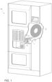
- reference numeral 1A references as a whole a beverage vending machine.
- the beverage vending machine 1 has the general shape of a wardrobe closed at the front by a door and is provided, on said door, with a beverage selection interface and with a cup withdrawal compartment accessible from the outside to allow a user to withdraw a cup containing a selected beverage.
- the beverage vending machine 1A is additionally provided with a stirrer dispenser 1 configured to form and dispense disposable stirrers 2 from a flat strip 3 of ecological food-grade material, preferably biodegradable or compostable and preferably plastic-free, for instance waterproof cardboard.
- the stirrer dispenser 1 is arranged inside the beverage vending machine 1A and is controllable by an electronic control unit of the beverage vending machine to automatically dispense, during a beverage preparation process, a stirrer 2 directly into a cup previously arranged in a withdrawal compartment to receive the beverage selected by a user.
- the electronic control unit may be programmed to operate the stirrer dispenser 1 to dispense a stirrer 2 every time a beverage is selected or when a given quantity of sugar in the selected beverage is requested by the user or, independently of a request for sugar, depending on the type of beverage selected, such as in the case of soluble beverages.
- the stirrer dispenser 1 may be arranged in the beverage vending machine to be operated, in response to a specific user selection, to dispense a stirrer 2 only, independently of the beverage request.
- the stirrer dispenser 2 is arranged such that the stirrer 2 is dispensed inside a dedicated stirrer withdrawal area, separate from or contiguous to the cup withdrawal compartment, and accessible to the user from the outside.
- the stirrer dispenser 1 may be distinct from, and externally associated with, the beverage vending machine 1A so as to constitute an independent device that is operable by a user independently of the beverage vending machine 1A in order to dispense a stirrer 2 when requested.
- stirrer dispenser 1 is conveniently electronically controlled by the electronic control unit of the beverage vending machine 1A to dispense stirrers 2 of different lengths depending on the size of the cup that is selected by the electronic control unit to receive the beverage selected by the user.
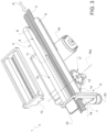
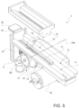
- the stirrer dispenser 1 comprises a feeding channel 4, which is slidably engaged, in a feeding direction D (indicated in Figures 3 and 4 by an arrow), by an end portion of the strip 3, which, during operation, is unwound from a storage in the form of a roll 5.
- the strip 3 may be stored in manners and forms different from a roll; for example, the strip 3 may be folded to form a bellow or with other folding methods which allow the achievement of a compact storage.
- the stirrer dispenser 1 further comprises a detaching device 6 associated with the feeding channel 4 to form a transverse detachment line on the strip 3, at a predetermined distance from the free end of the strip 3, which transverse detachment line defines, on the strip 3, an end piece of a given length forming a stirrer 2.
- the detaching device 6 is configured to form a complete transverse detachment line, i.e., to cut the strip 3 transversely.
- the detaching device 6 is preferably arranged at an outlet 7 of the feeding channel 4 such that, when the stirrer 2 is detached from the rest of the strip 3, the stirrer 2 is already arranged outside the feeding channel 4 and is free to fall by gravity, either directly or via a slide, into the cup arranged in the cup withdrawal compartment or in the stirrer withdrawal area for manual withdrawal by the user.
- the detaching device 6 may be configured to form an uncompleted transverse detachment line on the strip 3, i.e., to form a weakened or incision line or a perforated or pre-cut line so as to allow a user to manually detach the stirrer 2 from the rest of the strip 3 by simply pulling the stirrer 2.
- the detaching device 6 may be arranged at or upstream from the outlet 7 such that at least a portion of the stirrer 2 protrudes out of the outlet 7 into the stirrer withdrawal area and allows a user to grasp and detach the stirrer 2.
- the feeding channel 4 comprises an inlet portion 8 along which the strip 3 is advanced in a flat configuration while being guided laterally by two lateral walls 9 of the feeding channel 4.
- the feeding channel 4 further comprises a bending portion 10, which is arranged between the inlet portion 8 and the outlet 7 and has the function of bending the strip 3 longitudinally, while the latter advances toward the outlet 7, so as to give the stirrers 2 a more rigid and more manageable shape.
- a bending portion 10 which is arranged between the inlet portion 8 and the outlet 7 and has the function of bending the strip 3 longitudinally, while the latter advances toward the outlet 7, so as to give the stirrers 2 a more rigid and more manageable shape.
- the bending portion 10 is formed by two benders 11 and 12, which have respective shaping profiles and are mutually coupled so as to define a passage extending in the feeding direction D and having a cross-section of a given shape so as to shape the strip 3 longitudinally, when it is advanced through the passage, in accordance with said given shape.
- the shaping profiles of the benders 11 and 12 are such as to give the strip 2 an L-shaped cross-section; however, any other shape that is fit for the purpose may be used, for example a V, U or C shape.
- the bender 11 comprises a wedge-shaped member having an apex edge extending in the feeding direction D, and the bender 12 has a longitudinal groove with a shape complementary to the wedge-shaped member and coupled thereto to form a passage therebetween with a height equal to the thickness of the strip 3 and adapted to be slidably engaged by the strip 3.
- a strip 3 with a longitudinal weakened line is used ( Figures 2 , 3 , 6-8 ), which is formed on the strip 3 in such a way as to be arranged, when the strip 3 passes through the bending portion 10, at the apex edge of the bender 11 so as to ensure that the strip 3 is bent exactly along the longitudinal weakened line.
- one of the two benders is mounted in a fixed manner and is integral with the feeding channel 4, while the bender 12 is removably coupled to the bender 11 to allow an operator either to remove it for maintenance ( Figure 3 ) or to position the initial end of the strip 3 along the feeding channel 4 during replacement of the roll 5,
- the strip 3 is conveniently fed along the feeding channel 4 by a feeding device 13.
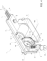
- the feeding device 13 comprises a dragging wheel 13, which lies on a plane parallel to the feeding direction D of the strip 3 along the feeding channel 4 and is arranged underneath the feeding channel 4 with one of its peripheral edges 14 substantially tangent to the feeding channel 4 in such a manner as to extend through an aperture 15 made through the feeding channel 4.
- the feeding direction D is horizontal and the dragging wheel 13 lies on a vertical plane.
- the peripheral edge 14 of the dragging wheel 13 is provided with small sharp teeth 14a which protrude, through the aperture 15, towards the feeding channel 4 far enough to penetrate, when the dragging wheel 13 turns and the strip 3 is advanced along the feeding channel 4, the lower surface of the strip 3 so as to impart to the strip 3 a dragging motion in the feeding direction D.
- the aperture 15 is formed at the bending portion 10 of the feeding channel 4.
- the dragging wheel is arranged below the bender 12 which thus opposes the thrust imparted by the teeth 14a to the strip 3, so resulting not only in a more efficient dragging action on the strip 3 being, but, above all, in an enduring longitudinal bending of the strip 3.
- the teeth 14a may be replaced with small rollers or other dragging mechanisms capable of bringing about a dragging motion of the strip 3 in the feeding direction D by penetration, by suction, by friction or in any other suitable way.
- the dragging wheel 13 is conveniently driven by an electric motor 16 to rotate about an axis 16a transverse to the feeding direction D of the strip 3, in a direction of rotation concordant with the feeding direction D.
- the dragging wheel 13 is conveniently provided with an angular position sensor 17 in the form of a rotary encoder associated with the axis 16a and electrically connected to an electronic control unit of the beverage vending machine 1A to control the feeding of the strip 3 and, thus, the length of the stirrer 2 to be dispensed.
- the presence of the strip 3 on the feeding channel 4 is detected by means of a presence or proximity sensor 18 arranged at the inlet portion of the feeding channel 4.
- the detaching device 6 conveniently comprises a reciprocating blade 19 arranged before the outlet 7 to reciprocate in a direction transverse to the feeding direction D between a rest position ( Figure 6 ), in which the blade 19 leaves the outlet 7 free, and a cutting position ( Figure 8 ), in which the blade 19 extends through the outlet 7 and cuts the piece of strip 3 protruding from the outlet 7 to form a stirrer 2.
- the blade 19 is caused to reciprocate by the electronic control unit by means of an electromagnet 20, which, when electrically energised, attracts the blade 19 and move it from the rest position to the cutting position against the bias of a return spring 21, which is arranged to cause the blade 19 to move back into the rest position when the electromagnet is electrically de-energised.
- actuating devices may be used to move the blade 19.
- a single electric motor may be used to operate the dragging wheel 13 and the detaching device 6.
- the blade 19 is further provided, at ad end thereof, with a lever 22 to allow an operator, during replacement of the roll 5, to operate the blade 19 manually and remove the end of the strip 3 after positioning it in the feeding channel 4.
Landscapes
- Engineering & Computer Science (AREA)
- Mechanical Engineering (AREA)
- Physics & Mathematics (AREA)
- General Physics & Mathematics (AREA)
- Life Sciences & Earth Sciences (AREA)
- Forests & Forestry (AREA)
- Beverage Vending Machines With Cups, And Gas Or Electricity Vending Machines (AREA)
- Table Equipment (AREA)
Claims (9)
- Ein Getränkeautomat (1A), der einen Rührer-Spender (1) aufweist, der innerhalb des Getränkeautomaten (1A) angeordnet ist, um Einweg-Rührer (2) auszugeben; und eine elektronische Steuereinheit, die eingerichtet ist, einen Betrieb des Rührer-Spenders (1) zu steuern;wobei der Rührer-Spender (1) so gestaltet ist, dass er Einweg-Rührer (2) aus einem Streifen (3) formt und ausgibt, der aus lebensmitteltauglichem Material besteht, das vorzugsweise biologisch abbaubar oder kompostierbar und vorzugsweise plastikfrei und wasserdicht ist,wobei der Rührer-Spender (1) einen Zuführkanal (4) und eine Zuführvorrichtung (13) aufweist, die mit dem Zuführkanal (4) verbunden und geeignet ist, mit dem Streifen (3) in Eingriff zu kommen, um dem Streifen (3) einen Schub zu verleihen, um den Streifen (3) entlang einer Zuführrichtung (D) zu einem Auslass (7) des Rührer-Spenders (1) zuzuführen;wobei der Rührer-Spender (1) ferner eine Abtrennvorrichtung (6) aufweist, die eingerichtet ist, ein Endstück des Streifens (3) mit einer solchen Länge abzutrennen, dass es als Rührer verwendet werden kann;wobei der Rührer-Spender (1) durch die elektronische Steuereinheit steuerbar ist, entweder während eines Getränkezubereitungsprozesses automatisch einen Rührer (2) in einen Becher abzugeben, der zuvor in einem Entnahmefach des Getränkeautomaten (1A) angeordnet wurde, um das von einem Benutzer ausgewählte Getränk aufzunehmen, oder, und zwar als Reaktion auf eine spezifische Benutzerauswahl, unabhängig von einer Getränkeanforderung einen Rührer (2) innerhalb eines speziellen Rührer-Entnahmebereichs abzugeben, der entweder von dem Becher-Entnahmefach getrennt ist oder an dieses angrenzt und der für einen Benutzer von außen zugänglich ist.
- Der Getränkeautomat (1A) nach Anspruch 1,
wobei der Zuführkanal (4) einen Biegeabschnitt (10) aufweist, der sich in der Zuführrichtung (D) stromaufwärts vom Auslass (7) befindet und der eingerichtet ist, den Streifen (3) während des Zuführens zum Auslass (7) in Längsrichtung zu biegen, um den Rührern (2) einen bestimmten Querschnitt, vorzugsweise L- oder V-förmig, zu verleihen. - Der Getränkeautomat (1A) nach Anspruch 2,
wobei der Zuführkanal (4) zum Aufnehmen des Streifens (3) in einer flachen Konfiguration angepasst ist und wobei der Biegeabschnitt zwei Biegeeinrichtungen (11, 12) mit komplementären Formgebungsprofilen aufweist, die miteinander gekoppelt sind, um dazwischen einen Durchgang mit einem bestimmten Querschnitt zu definieren, und die angepasst sind, um von dem Streifen (3) durchquert zu werden, wenn er in der Zuführrichtung (D) zugeführt wird. - Der Getränkeautomat (1A) nach Anspruch 3,
wobei eine der beiden Biegeeinrichtungen (11) durch ein keilförmiges Element definiert ist, das eine sich in der Zuführrichtung (D) erstreckende Scheitelkante aufweist, und wobei die andere Biegeeinrichtung (12) eine Längsnut mit einer zu dem keilförmigen Element komplementären Form aufweist und mit diesem so verbunden ist, dass dazwischen ein Durchgang mit einer Höhe gebildet wird, die gleich der Dicke des Streifens (3) ist, und der angepasst ist, um von dem Streifen (3) gleitend erfasst zu werden. - Der Getränkeautomat (1A) nach einem der vorhergehenden Ansprüche, wobei die Zuführvorrichtung (13) so gestaltet ist, dass sie den Streifen (3) durch einen Eingriff auf Basis von Durchdringung, Reibung oder Sog mitzieht.
- Der Getränkeautomat (1A) nach einem der vorhergehenden Ansprüche, wobei die Zuführvorrichtung (13) ein Antriebsrad (13) mit einer Umfangskante (14) aufweist, die tangential zum Zuführkanal (4) angeordnet und mit Spitzen (14a) versehen ist, die eingerichtet sind, in den Zuführkanal (4) hineinzuragen, um in Eingriff zu kommen, wenn sich das Antriebsrad (13) dreht und der Streifen (3) entlang des Zuführkanals (4) zugeführt wird, mit einer Oberfläche des Streifens (3), um dem Streifen (3) eine Zugwirkung in der Zuführrichtung (D) zu verleihen.
- Der Getränkeautomat (1A) nach Anspruch 4,
wobei die Zuführvorrichtung (13) an dem Biegeabschnitt (10) angeordnet und eingerichtet ist, mit dem Biegeabschnitt (10) zusammenzuwirken, um dem Streifen (3) zusätzlich zu einem Schub in der Zuführrichtung (D) auch einen Schub quer zur Zuführrichtung (D) zu verleihen, um den Streifen (3) in den Durchgang zu drücken und das Biegen des Streifens (3) zu erleichtern. - Der Getränkeautomat (1A) nach einem der vorhergehenden Ansprüche, wobei die Abtrennvorrichtung (6) eine hin- und hergehende Klinge (19) aufweist, die in einer Richtung quer zur Zuführrichtung (D) hin- und herbewegt werden kann.
- Der Getränkeautomat (1A) nach einem der vorhergehenden Ansprüche, wobei die elektronische Steuereinheit eingerichtet ist, den Rührer-Spender (1) zu betätigen, um Rührer (2) unterschiedlicher Längen zu bilden, und zwar abhängig von der Art des Bechers, in den das Getränk ausgegeben werden soll.
Applications Claiming Priority (3)
| Application Number | Priority Date | Filing Date | Title |
|---|---|---|---|
| EP19172645 | 2019-05-03 | ||
| IT102019000013083A IT201900013083A1 (it) | 2019-07-26 | 2019-07-26 | Erogatore di palette mescolatrici per un distributore automatico di bevande |
| PCT/IB2020/054097 WO2020225669A1 (en) | 2019-05-03 | 2020-04-30 | Stirrer dispenser for a beverage vending machine |
Publications (2)
| Publication Number | Publication Date |
|---|---|
| EP3963552A1 EP3963552A1 (de) | 2022-03-09 |
| EP3963552B1 true EP3963552B1 (de) | 2023-09-13 |
Family
ID=70975904
Family Applications (1)
| Application Number | Title | Priority Date | Filing Date |
|---|---|---|---|
| EP20730320.7A Active EP3963552B1 (de) | 2019-05-03 | 2020-04-30 | Rührer-spender für einen getränkeautomaten |
Country Status (6)
| Country | Link |
|---|---|
| US (1) | US11904488B2 (de) |
| EP (1) | EP3963552B1 (de) |
| CN (1) | CN113767426B (de) |
| BR (1) | BR112021022048A2 (de) |
| ES (1) | ES2961742T3 (de) |
| WO (1) | WO2020225669A1 (de) |
Families Citing this family (3)
| Publication number | Priority date | Publication date | Assignee | Title |
|---|---|---|---|---|
| WO2023012634A1 (en) * | 2021-08-03 | 2023-02-09 | Bianucci, Stefano | Machine and method for producing drink stirring sticks made of paper material |
| IT202100021173A1 (it) | 2021-08-04 | 2023-02-04 | Evoca Spa | Gruppo di alimentazione di un nastro, particolarmente per un erogatore di palette di mescolamento in un distributore automatico di bevande |
| EP4416710B1 (de) * | 2021-10-15 | 2025-03-12 | EVOCA S.p.A. | Rührstabformanordnung für einen rührstabspender in einem getränkeverkaufsautomat |
Family Cites Families (12)
| Publication number | Priority date | Publication date | Assignee | Title |
|---|---|---|---|---|
| DK96964C (da) * | 1961-12-12 | 1963-09-23 | Gram Brdr As | Foldemekanisme til en pakkemaskine. |
| US4725218A (en) * | 1986-06-23 | 1988-02-16 | Facile Technologies, Inc. | Apparatus for folding tape |
| US5381925A (en) * | 1993-07-22 | 1995-01-17 | Cervantes; Pat | Stirrer/straw dispenser |
| ITVR20040061A1 (it) | 2004-04-16 | 2004-07-16 | Fas International Spa | Dispensatore di zucchero e di palette |
| US20060199719A1 (en) * | 2005-03-02 | 2006-09-07 | White Thornton C | Roll stand paper guide |
| CA2645830C (en) | 2006-03-15 | 2013-08-27 | Toray Industries, Inc. | Process for manufacturing preform and apparatus therefor |
| FR2907654B1 (fr) * | 2006-10-31 | 2010-01-29 | Georgia Pacific France | Procede, dispositif de fabrication et rouleaux associes formes de feuilles a decoupes et predecoupes alternees |
| US20080128445A1 (en) * | 2006-12-05 | 2008-06-05 | Hsi Ping Huang | Dispenser having advertisement counting effect |
| AU2011246922B2 (en) * | 2010-04-26 | 2015-05-14 | Saga Coffee S.P.A. | A stirrer or spoon dispenser for beverage dispensing machines |
| RU2710351C2 (ru) * | 2015-04-30 | 2019-12-25 | Н ЭНД В ГЛОБАЛ ВЕНДИНГ С.п.А. | Машина для продажи напитков |
| DE202016001413U1 (de) * | 2016-03-07 | 2017-06-12 | SETTER GmbH & Co. Papierverarbeitung | Papierprofil und Verwendung eines Papierprofils |
| CN109094115B (zh) * | 2018-08-01 | 2024-07-16 | 常州市诚鑫环保科技有限公司 | 纸塑吸管及其制造方法 |
-
2020
- 2020-04-30 US US17/594,691 patent/US11904488B2/en active Active
- 2020-04-30 WO PCT/IB2020/054097 patent/WO2020225669A1/en not_active Ceased
- 2020-04-30 EP EP20730320.7A patent/EP3963552B1/de active Active
- 2020-04-30 CN CN202080033153.XA patent/CN113767426B/zh not_active Expired - Fee Related
- 2020-04-30 BR BR112021022048A patent/BR112021022048A2/pt not_active Application Discontinuation
- 2020-04-30 ES ES20730320T patent/ES2961742T3/es active Active
Also Published As
| Publication number | Publication date |
|---|---|
| CN113767426B (zh) | 2023-06-23 |
| BR112021022048A2 (pt) | 2022-03-22 |
| US20220203567A1 (en) | 2022-06-30 |
| US11904488B2 (en) | 2024-02-20 |
| ES2961742T3 (es) | 2024-03-13 |
| EP3963552A1 (de) | 2022-03-09 |
| WO2020225669A1 (en) | 2020-11-12 |
| CN113767426A (zh) | 2021-12-07 |
Similar Documents
| Publication | Publication Date | Title |
|---|---|---|
| EP3963552B1 (de) | Rührer-spender für einen getränkeautomaten | |
| US10531770B2 (en) | Automatic napkin dispenser | |
| US10993591B2 (en) | Automatic napkin dispenser | |
| CA2864324C (en) | Automatic napkin dispenser | |
| EP2877402A1 (de) | Bandspender mit verbessertem benetzungssystem | |
| CN109502071B (zh) | 一种防霉干燥片生产包装机 | |
| US11297984B2 (en) | Automatic napkin dispenser | |
| US1976788A (en) | Machine for delivering sheets from a stack | |
| RU2799394C2 (ru) | Устройство для выдачи палочек для перемешивания, предназначенное для автомата для продажи напитков | |
| EP3232884B1 (de) | Automatischer serviettenspender | |
| IT201900013083A1 (it) | Erogatore di palette mescolatrici per un distributore automatico di bevande | |
| CN109621649B (zh) | 一种防霉干燥片及其生产工艺 | |
| US20050061127A1 (en) | Device for dispensing a paper product | |
| US3074607A (en) | Stamp vending machine | |
| US2798293A (en) | Automatic slicer for bars of butter or the like | |
| HK1203042B (en) | Automatic napkin dispenser | |
| RU2021134377A (ru) | Устройство для выдачи палочек для перемешивания, предназначенное для автомата для продажи напитков | |
| HK1243294B (zh) | 自动餐巾分配器 |
Legal Events
| Date | Code | Title | Description |
|---|---|---|---|
| STAA | Information on the status of an ep patent application or granted ep patent |
Free format text: STATUS: UNKNOWN |
|
| STAA | Information on the status of an ep patent application or granted ep patent |
Free format text: STATUS: THE INTERNATIONAL PUBLICATION HAS BEEN MADE |
|
| PUAI | Public reference made under article 153(3) epc to a published international application that has entered the european phase |
Free format text: ORIGINAL CODE: 0009012 |
|
| STAA | Information on the status of an ep patent application or granted ep patent |
Free format text: STATUS: REQUEST FOR EXAMINATION WAS MADE |
|
| 17P | Request for examination filed |
Effective date: 20211126 |
|
| AK | Designated contracting states |
Kind code of ref document: A1 Designated state(s): AL AT BE BG CH CY CZ DE DK EE ES FI FR GB GR HR HU IE IS IT LI LT LU LV MC MK MT NL NO PL PT RO RS SE SI SK SM TR |
|
| DAV | Request for validation of the european patent (deleted) | ||
| DAX | Request for extension of the european patent (deleted) | ||
| RAP3 | Party data changed (applicant data changed or rights of an application transferred) |
Owner name: EVOCA S.P.A. |
|
| REG | Reference to a national code |
Ref country code: DE Ref legal event code: R079 Free format text: PREVIOUS MAIN CLASS: G07F0013100000 Ipc: G07F0011700000 Ref country code: DE Ref legal event code: R079 Ref document number: 602020017650 Country of ref document: DE Free format text: PREVIOUS MAIN CLASS: G07F0013100000 Ipc: G07F0011700000 |
|
| RIC1 | Information provided on ipc code assigned before grant |
Ipc: B31F 1/00 20060101ALI20230303BHEP Ipc: B31D 5/00 20060101ALI20230303BHEP Ipc: B29C 53/06 20060101ALI20230303BHEP Ipc: B26D 5/08 20060101ALI20230303BHEP Ipc: B26D 1/08 20060101ALI20230303BHEP Ipc: G07F 13/10 20060101ALI20230303BHEP Ipc: G07F 11/70 20060101AFI20230303BHEP |
|
| GRAP | Despatch of communication of intention to grant a patent |
Free format text: ORIGINAL CODE: EPIDOSNIGR1 |
|
| STAA | Information on the status of an ep patent application or granted ep patent |
Free format text: STATUS: GRANT OF PATENT IS INTENDED |
|
| INTG | Intention to grant announced |
Effective date: 20230419 |
|
| P01 | Opt-out of the competence of the unified patent court (upc) registered |
Effective date: 20230530 |
|
| GRAS | Grant fee paid |
Free format text: ORIGINAL CODE: EPIDOSNIGR3 |
|
| GRAA | (expected) grant |
Free format text: ORIGINAL CODE: 0009210 |
|
| STAA | Information on the status of an ep patent application or granted ep patent |
Free format text: STATUS: THE PATENT HAS BEEN GRANTED |
|
| AK | Designated contracting states |
Kind code of ref document: B1 Designated state(s): AL AT BE BG CH CY CZ DE DK EE ES FI FR GB GR HR HU IE IS IT LI LT LU LV MC MK MT NL NO PL PT RO RS SE SI SK SM TR |
|
| REG | Reference to a national code |
Ref country code: CH Ref legal event code: EP |
|
| REG | Reference to a national code |
Ref country code: DE Ref legal event code: R096 Ref document number: 602020017650 Country of ref document: DE |
|
| REG | Reference to a national code |
Ref country code: NL Ref legal event code: FP Ref country code: IE Ref legal event code: FG4D |
|
| REG | Reference to a national code |
Ref country code: SE Ref legal event code: TRGR |
|
| REG | Reference to a national code |
Ref country code: LT Ref legal event code: MG9D |
|
| PG25 | Lapsed in a contracting state [announced via postgrant information from national office to epo] |
Ref country code: GR Free format text: LAPSE BECAUSE OF FAILURE TO SUBMIT A TRANSLATION OF THE DESCRIPTION OR TO PAY THE FEE WITHIN THE PRESCRIBED TIME-LIMIT Effective date: 20231214 |
|
| PG25 | Lapsed in a contracting state [announced via postgrant information from national office to epo] |
Ref country code: RS Free format text: LAPSE BECAUSE OF FAILURE TO SUBMIT A TRANSLATION OF THE DESCRIPTION OR TO PAY THE FEE WITHIN THE PRESCRIBED TIME-LIMIT Effective date: 20230913 Ref country code: NO Free format text: LAPSE BECAUSE OF FAILURE TO SUBMIT A TRANSLATION OF THE DESCRIPTION OR TO PAY THE FEE WITHIN THE PRESCRIBED TIME-LIMIT Effective date: 20231213 Ref country code: LV Free format text: LAPSE BECAUSE OF FAILURE TO SUBMIT A TRANSLATION OF THE DESCRIPTION OR TO PAY THE FEE WITHIN THE PRESCRIBED TIME-LIMIT Effective date: 20230913 Ref country code: LT Free format text: LAPSE BECAUSE OF FAILURE TO SUBMIT A TRANSLATION OF THE DESCRIPTION OR TO PAY THE FEE WITHIN THE PRESCRIBED TIME-LIMIT Effective date: 20230913 Ref country code: HR Free format text: LAPSE BECAUSE OF FAILURE TO SUBMIT A TRANSLATION OF THE DESCRIPTION OR TO PAY THE FEE WITHIN THE PRESCRIBED TIME-LIMIT Effective date: 20230913 Ref country code: GR Free format text: LAPSE BECAUSE OF FAILURE TO SUBMIT A TRANSLATION OF THE DESCRIPTION OR TO PAY THE FEE WITHIN THE PRESCRIBED TIME-LIMIT Effective date: 20231214 Ref country code: FI Free format text: LAPSE BECAUSE OF FAILURE TO SUBMIT A TRANSLATION OF THE DESCRIPTION OR TO PAY THE FEE WITHIN THE PRESCRIBED TIME-LIMIT Effective date: 20230913 |
|
| REG | Reference to a national code |
Ref country code: AT Ref legal event code: MK05 Ref document number: 1612087 Country of ref document: AT Kind code of ref document: T Effective date: 20230913 |
|
| REG | Reference to a national code |
Ref country code: ES Ref legal event code: FG2A Ref document number: 2961742 Country of ref document: ES Kind code of ref document: T3 Effective date: 20240313 |
|
| PG25 | Lapsed in a contracting state [announced via postgrant information from national office to epo] |
Ref country code: IS Free format text: LAPSE BECAUSE OF FAILURE TO SUBMIT A TRANSLATION OF THE DESCRIPTION OR TO PAY THE FEE WITHIN THE PRESCRIBED TIME-LIMIT Effective date: 20240113 |
|
| PG25 | Lapsed in a contracting state [announced via postgrant information from national office to epo] |
Ref country code: AT Free format text: LAPSE BECAUSE OF FAILURE TO SUBMIT A TRANSLATION OF THE DESCRIPTION OR TO PAY THE FEE WITHIN THE PRESCRIBED TIME-LIMIT Effective date: 20230913 |
|
| PG25 | Lapsed in a contracting state [announced via postgrant information from national office to epo] |
Ref country code: SM Free format text: LAPSE BECAUSE OF FAILURE TO SUBMIT A TRANSLATION OF THE DESCRIPTION OR TO PAY THE FEE WITHIN THE PRESCRIBED TIME-LIMIT Effective date: 20230913 Ref country code: RO Free format text: LAPSE BECAUSE OF FAILURE TO SUBMIT A TRANSLATION OF THE DESCRIPTION OR TO PAY THE FEE WITHIN THE PRESCRIBED TIME-LIMIT Effective date: 20230913 Ref country code: IS Free format text: LAPSE BECAUSE OF FAILURE TO SUBMIT A TRANSLATION OF THE DESCRIPTION OR TO PAY THE FEE WITHIN THE PRESCRIBED TIME-LIMIT Effective date: 20240113 Ref country code: EE Free format text: LAPSE BECAUSE OF FAILURE TO SUBMIT A TRANSLATION OF THE DESCRIPTION OR TO PAY THE FEE WITHIN THE PRESCRIBED TIME-LIMIT Effective date: 20230913 Ref country code: CZ Free format text: LAPSE BECAUSE OF FAILURE TO SUBMIT A TRANSLATION OF THE DESCRIPTION OR TO PAY THE FEE WITHIN THE PRESCRIBED TIME-LIMIT Effective date: 20230913 Ref country code: AT Free format text: LAPSE BECAUSE OF FAILURE TO SUBMIT A TRANSLATION OF THE DESCRIPTION OR TO PAY THE FEE WITHIN THE PRESCRIBED TIME-LIMIT Effective date: 20230913 Ref country code: SK Free format text: LAPSE BECAUSE OF FAILURE TO SUBMIT A TRANSLATION OF THE DESCRIPTION OR TO PAY THE FEE WITHIN THE PRESCRIBED TIME-LIMIT Effective date: 20230913 Ref country code: PT Free format text: LAPSE BECAUSE OF FAILURE TO SUBMIT A TRANSLATION OF THE DESCRIPTION OR TO PAY THE FEE WITHIN THE PRESCRIBED TIME-LIMIT Effective date: 20240115 |
|
| PGFP | Annual fee paid to national office [announced via postgrant information from national office to epo] |
Ref country code: NL Payment date: 20240425 Year of fee payment: 5 |
|
| PG25 | Lapsed in a contracting state [announced via postgrant information from national office to epo] |
Ref country code: PL Free format text: LAPSE BECAUSE OF FAILURE TO SUBMIT A TRANSLATION OF THE DESCRIPTION OR TO PAY THE FEE WITHIN THE PRESCRIBED TIME-LIMIT Effective date: 20230913 |
|
| REG | Reference to a national code |
Ref country code: DE Ref legal event code: R097 Ref document number: 602020017650 Country of ref document: DE |
|
| PG25 | Lapsed in a contracting state [announced via postgrant information from national office to epo] |
Ref country code: DK Free format text: LAPSE BECAUSE OF FAILURE TO SUBMIT A TRANSLATION OF THE DESCRIPTION OR TO PAY THE FEE WITHIN THE PRESCRIBED TIME-LIMIT Effective date: 20230913 |
|
| PLBE | No opposition filed within time limit |
Free format text: ORIGINAL CODE: 0009261 |
|
| STAA | Information on the status of an ep patent application or granted ep patent |
Free format text: STATUS: NO OPPOSITION FILED WITHIN TIME LIMIT |
|
| PG25 | Lapsed in a contracting state [announced via postgrant information from national office to epo] |
Ref country code: DK Free format text: LAPSE BECAUSE OF FAILURE TO SUBMIT A TRANSLATION OF THE DESCRIPTION OR TO PAY THE FEE WITHIN THE PRESCRIBED TIME-LIMIT Effective date: 20230913 |
|
| 26N | No opposition filed |
Effective date: 20240614 |
|
| PGFP | Annual fee paid to national office [announced via postgrant information from national office to epo] |
Ref country code: SE Payment date: 20240527 Year of fee payment: 5 |
|
| PG25 | Lapsed in a contracting state [announced via postgrant information from national office to epo] |
Ref country code: SI Free format text: LAPSE BECAUSE OF FAILURE TO SUBMIT A TRANSLATION OF THE DESCRIPTION OR TO PAY THE FEE WITHIN THE PRESCRIBED TIME-LIMIT Effective date: 20230913 |
|
| PG25 | Lapsed in a contracting state [announced via postgrant information from national office to epo] |
Ref country code: SI Free format text: LAPSE BECAUSE OF FAILURE TO SUBMIT A TRANSLATION OF THE DESCRIPTION OR TO PAY THE FEE WITHIN THE PRESCRIBED TIME-LIMIT Effective date: 20230913 |
|
| PG25 | Lapsed in a contracting state [announced via postgrant information from national office to epo] |
Ref country code: BG Free format text: LAPSE BECAUSE OF FAILURE TO SUBMIT A TRANSLATION OF THE DESCRIPTION OR TO PAY THE FEE WITHIN THE PRESCRIBED TIME-LIMIT Effective date: 20230913 |
|
| PG25 | Lapsed in a contracting state [announced via postgrant information from national office to epo] |
Ref country code: MC Free format text: LAPSE BECAUSE OF FAILURE TO SUBMIT A TRANSLATION OF THE DESCRIPTION OR TO PAY THE FEE WITHIN THE PRESCRIBED TIME-LIMIT Effective date: 20230913 |
|
| PG25 | Lapsed in a contracting state [announced via postgrant information from national office to epo] |
Ref country code: MC Free format text: LAPSE BECAUSE OF FAILURE TO SUBMIT A TRANSLATION OF THE DESCRIPTION OR TO PAY THE FEE WITHIN THE PRESCRIBED TIME-LIMIT Effective date: 20230913 Ref country code: BG Free format text: LAPSE BECAUSE OF FAILURE TO SUBMIT A TRANSLATION OF THE DESCRIPTION OR TO PAY THE FEE WITHIN THE PRESCRIBED TIME-LIMIT Effective date: 20230913 |
|
| REG | Reference to a national code |
Ref country code: CH Ref legal event code: PL |
|
| PG25 | Lapsed in a contracting state [announced via postgrant information from national office to epo] |
Ref country code: LU Free format text: LAPSE BECAUSE OF NON-PAYMENT OF DUE FEES Effective date: 20240430 |
|
| GBPC | Gb: european patent ceased through non-payment of renewal fee |
Effective date: 20240430 |
|
| REG | Reference to a national code |
Ref country code: BE Ref legal event code: MM Effective date: 20240430 |
|
| PG25 | Lapsed in a contracting state [announced via postgrant information from national office to epo] |
Ref country code: LU Free format text: LAPSE BECAUSE OF NON-PAYMENT OF DUE FEES Effective date: 20240430 |
|
| PG25 | Lapsed in a contracting state [announced via postgrant information from national office to epo] |
Ref country code: BE Free format text: LAPSE BECAUSE OF NON-PAYMENT OF DUE FEES Effective date: 20240430 |
|
| PG25 | Lapsed in a contracting state [announced via postgrant information from national office to epo] |
Ref country code: GB Free format text: LAPSE BECAUSE OF NON-PAYMENT OF DUE FEES Effective date: 20240430 |
|
| PG25 | Lapsed in a contracting state [announced via postgrant information from national office to epo] |
Ref country code: GB Free format text: LAPSE BECAUSE OF NON-PAYMENT OF DUE FEES Effective date: 20240430 Ref country code: BE Free format text: LAPSE BECAUSE OF NON-PAYMENT OF DUE FEES Effective date: 20240430 Ref country code: CH Free format text: LAPSE BECAUSE OF NON-PAYMENT OF DUE FEES Effective date: 20240430 |
|
| PG25 | Lapsed in a contracting state [announced via postgrant information from national office to epo] |
Ref country code: IE Free format text: LAPSE BECAUSE OF NON-PAYMENT OF DUE FEES Effective date: 20240430 |
|
| PGFP | Annual fee paid to national office [announced via postgrant information from national office to epo] |
Ref country code: DE Payment date: 20250428 Year of fee payment: 6 |
|
| PGFP | Annual fee paid to national office [announced via postgrant information from national office to epo] |
Ref country code: ES Payment date: 20250513 Year of fee payment: 6 |
|
| PGFP | Annual fee paid to national office [announced via postgrant information from national office to epo] |
Ref country code: IT Payment date: 20250402 Year of fee payment: 6 |
|
| PGFP | Annual fee paid to national office [announced via postgrant information from national office to epo] |
Ref country code: FR Payment date: 20250424 Year of fee payment: 6 |
|
| PG25 | Lapsed in a contracting state [announced via postgrant information from national office to epo] |
Ref country code: CY Free format text: LAPSE BECAUSE OF FAILURE TO SUBMIT A TRANSLATION OF THE DESCRIPTION OR TO PAY THE FEE WITHIN THE PRESCRIBED TIME-LIMIT; INVALID AB INITIO Effective date: 20200430 |
|
| PG25 | Lapsed in a contracting state [announced via postgrant information from national office to epo] |
Ref country code: HU Free format text: LAPSE BECAUSE OF FAILURE TO SUBMIT A TRANSLATION OF THE DESCRIPTION OR TO PAY THE FEE WITHIN THE PRESCRIBED TIME-LIMIT; INVALID AB INITIO Effective date: 20200430 |
|
| REG | Reference to a national code |
Ref country code: NL Ref legal event code: MM Effective date: 20250501 |
|
| PG25 | Lapsed in a contracting state [announced via postgrant information from national office to epo] |
Ref country code: NL Free format text: LAPSE BECAUSE OF NON-PAYMENT OF DUE FEES Effective date: 20250501 |
|
| PG25 | Lapsed in a contracting state [announced via postgrant information from national office to epo] |
Ref country code: SE Free format text: LAPSE BECAUSE OF NON-PAYMENT OF DUE FEES Effective date: 20250501 |
|
| REG | Reference to a national code |
Ref country code: SE Ref legal event code: EUG |