EP3963296B1 - Systeme und verfahren zur füllstandsmessung eines silos - Google Patents
Systeme und verfahren zur füllstandsmessung eines silos Download PDFInfo
- Publication number
- EP3963296B1 EP3963296B1 EP20721616.9A EP20721616A EP3963296B1 EP 3963296 B1 EP3963296 B1 EP 3963296B1 EP 20721616 A EP20721616 A EP 20721616A EP 3963296 B1 EP3963296 B1 EP 3963296B1
- Authority
- EP
- European Patent Office
- Prior art keywords
- silo
- deformation
- measurement signal
- sensor
- deformation sensor
- Prior art date
- Legal status (The legal status is an assumption and is not a legal conclusion. Google has not performed a legal analysis and makes no representation as to the accuracy of the status listed.)
- Active
Links
Images


Classifications
-
- G—PHYSICS
- G01—MEASURING; TESTING
- G01F—MEASURING VOLUME, VOLUME FLOW, MASS FLOW OR LIQUID LEVEL; METERING BY VOLUME
- G01F23/00—Indicating or measuring liquid level or level of fluent solid material, e.g. indicating in terms of volume or indicating by means of an alarm
- G01F23/20—Indicating or measuring liquid level or level of fluent solid material, e.g. indicating in terms of volume or indicating by means of an alarm by measurement of weight, e.g. to determine the level of stored liquefied gas
-
- G—PHYSICS
- G01—MEASURING; TESTING
- G01K—MEASURING TEMPERATURE; MEASURING QUANTITY OF HEAT; THERMALLY-SENSITIVE ELEMENTS NOT OTHERWISE PROVIDED FOR
- G01K13/00—Thermometers specially adapted for specific purposes
-
- G—PHYSICS
- G01—MEASURING; TESTING
- G01G—WEIGHING
- G01G17/00—Apparatus for or methods of weighing material of special form or property
- G01G17/04—Apparatus for or methods of weighing material of special form or property for weighing fluids, e.g. gases, pastes
-
- G—PHYSICS
- G01—MEASURING; TESTING
- G01G—WEIGHING
- G01G23/00—Auxiliary devices for weighing apparatus
- G01G23/18—Indicating devices, e.g. for remote indication; Recording devices; Scales, e.g. graduated
- G01G23/36—Indicating the weight by electrical means, e.g. using photoelectric cells
- G01G23/37—Indicating the weight by electrical means, e.g. using photoelectric cells involving digital counting
- G01G23/3728—Indicating the weight by electrical means, e.g. using photoelectric cells involving digital counting with wireless means
- G01G23/3735—Indicating the weight by electrical means, e.g. using photoelectric cells involving digital counting with wireless means using a digital network
-
- G—PHYSICS
- G01—MEASURING; TESTING
- G01G—WEIGHING
- G01G3/00—Weighing apparatus characterised by the use of elastically-deformable members, e.g. spring balances
- G01G3/12—Weighing apparatus characterised by the use of elastically-deformable members, e.g. spring balances wherein the weighing element is in the form of a solid body stressed by pressure or tension during weighing
-
- H—ELECTRICITY
- H04—ELECTRIC COMMUNICATION TECHNIQUE
- H04Q—SELECTING
- H04Q9/00—Arrangements in telecontrol or telemetry systems for selectively calling a substation from a main station, in which substation desired apparatus is selected for applying a control signal thereto or for obtaining measured values therefrom
Definitions
- the invention relates to measuring the filling level of bulk material storage and mixing silos. More particularly, the invention relates to a system and method for remote management of bulk material stocks present in such silos.
- CA2371068A1 a remote control system for the filling status of loading bins such as wood chip bins.
- the system CA2371068A1 uses a load sensor on each support beam.
- each load cell is formed into a square plate that has a mounting hole at each of its four corners.
- the system of CA2371068A1 uses a microcontroller placed near the load sensors, in order to average their measurements. Then, the microcontroller communicates the loading or filling status of the loading bin to a web server having a user interface to make this state available on the Internet.
- the dimensions of the load sensor must be modified.
- the invention aims to overcome these drawbacks.
- the invention aims in particular to propose an inexpensive and flexible system for determining data representative of the filling rate of a silo.
- the use of a metrological type system is not necessary provided that the reliability of the proposed system is ensured.
- the inventors found that the use of a single deformation sensor on a single foot of a silo was sufficient to enable reliable determination of the filling rate of said silo and/or the variation in its filling rate.
- the invention relates to a system for measuring the filling level of a silo for storing and mixing at least one bulk material, according to claim 1.
- the system is intended to operate with a silo which is provided with a plurality of ground support feet.
- the strain sensor comprises a connector electrically connected to the electronic circuit, the connector being provided for wiredly connecting the strain sensor to the first wireless communication means.
- the system further comprises a temperature sensor provided to measure at least one temperature in the vicinity of the support foot of the silo, convert the temperature into a temperature value and add the temperature value to the measurement signal.
- the system further comprises a geolocation sensor configured to determine a geographic position of the deformation sensor, convert the geographic position into a geographic position value, and add the geographic position value to the auxiliary signal.
- the processor determines the filling level of the silo as a function, in addition, of a rate of variation of the detected deformation values.
- the digital processing of the measurement signal and the auxiliary signal by processor includes the determination of a set of corrective parameters which make it possible to take into account the effect of the temperature on the support foot of the silo and the effect of time on the acquisition performance of the deformation sensor.
- the strain sensor comprises a test body which comprises two end sections through which the test body is fixed to the support foot of the silo.
- the deformation sensor is fixed to the support foot of the silo by screws.
- the deformation sensor can be fixed to the support foot of the silo by glue.
- system further comprises a housing adapted to enclose a middle section of the test body and the connector, the connector projecting from the housing.
- the invention also relates to a method for measuring the filling level of a silo for storing and mixing at least one bulk material, according to claim 11.
- the method is provided to operate with a silo which is provided with a plurality of ground support feet.
- FIG. 1 illustrates a system 100 for measuring the filling level of a silo 110 intended for the storage and/or mixing of at least one bulk material.
- the silo 110 is of a known type.
- bulk material is understood to mean any material suitable for being able to flow.
- the bulk material is chosen from the group formed by liquids and powdery materials.
- powdery materials include powdery solids.
- the silo 110 is provided with a plurality of support feet 111 on the ground.
- the silo 110 comprises two support feet 111 on the ground.
- the silo 110 may comprise more than two support feet 111 on the ground without requiring substantial modifications to the invention.
- the system 100 includes a single strain sensor 120, a first wireless communication means 130 and a remote server 140.
- the inventors have chosen to use, for each silo, a single deformation sensor with increased sensitivity.
- the deformation sensor according to the invention is of the type described in US 4,064,744 from Kistler. However, in the invention this sensor is used in a manner different from that recommended by US 4,064,744 . Indeed, in practice it is recommended to use several variants of the sensor depending on the type of silo foot. This is not the case in the invention where only one form of the sensor is used, regardless of the type of silo foot. Indeed, as explained below, all of the measurement processing is offset outside the sensor. It is therefore not necessary to modify its dimensions depending on the type of silo support foot.
- the deformation sensor 120 is intended to be fixed on a single support foot 111 of the silo 110 among the plurality of support feet 111 of the silo 110. Thus, in the invention, the deformation sensor 120 does not come into contact with the contents of the silo 110.
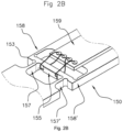
- the deformation sensor 120 comprises a test body which comprises two end sections 151, 152 through which the test body can be fixed to the support foot 111 of the silo 110.
- the deformation sensor 120 is fixed to the support foot 111 of the silo 110 by screws passing through the fixing holes 121, 122.
- the deformation sensor 120 is fixed to the support foot 111 of the silo 110 by other fixing or assembly means, such as glue.
- the deformation sensor 120 is fixed at a location on the support foot 111 of the silo 110 where a maximum deformation of the support foot 111 of the silo 110 can be measured.
- the deformation sensor 120 is fixed such that it can detect deformations of the support foot 111 in response to the introduction or extraction of the bulk material. According to the arrangement of the deformation sensor 120 on the support foot 111 of the silo 110, the deformation sensor 120 can detect deformations longitudinal and/or transverse forces undergone by the support foot 111 of the silo 110.
- test body is in the form of a plate formed from a single piece with a generally rectangular cross-section.
- the plate which forms the test body comprises at least one material capable of exhibiting homogeneous or non-homogeneous finite deformations and which is chosen from the group formed of metallic materials, polymer materials, ceramic materials and their composites.
- the plate which forms the test body has a generally rectangular parallelepiped shape with a width greater than 0.5 cm - in particular less than 2.5 cm, for example of the order of 1.5 cm to 2 cm -, a length greater than 5 cm - in particular less than 10 cm, for example of the order of 6.5 cm to 8 cm - and a height greater than 0.15 cm - in particular less than 0.4 cm, for example of the order of 0.28 cm to 0.3 cm.
- test body comprises a middle section 153 which comprises a deformation rod 154.
- the deformation rod 154 is arranged substantially perpendicular to the axis of the test body and mechanically connected separately to the end sections 151, 152.
- the deformation rod 154 is connected to the end sections 151, 152 by means of two pairs of connecting rods 157, 157', 158, 158' arranged symmetrically, but equally spaced.
- the deformation rod 154 comprises at least two resistive elements 155, 156 sensitive to deformation.
- the two resistive elements 155, 156 sensitive to deformation are glued to the deformation rod 154.
- any type of glue can be used, such as, for example, epoxy glue or cyanoacrylate glue.
- the strain-sensitive resistive elements 155, 156 are semiconductor strain gauges.
- each resistive element sensitive to deformation has at least one electrical characteristic which varies according to its deformation.
- the deformation sensor 120 is thus configured to convert into electrical signals the elongation, shortening, bending or buckling that the support foot 111 undergoes under the effect of a tensile or compressive force produced by the introduction or extraction of the bulk material.
- the strain sensor 120 is further provided to convert the detected strains into strain values and to generate at least one measuring signal which includes the strain values.
- the deformation sensor 120 further comprises an electronic circuit 159 electrically connected to the resistive elements 155, 156 sensitive to the deformation.
- each resistive element 155, 156 sensitive to the deformation has electrical connection pads to be electrically connected to the electronic circuit.
- the electronic circuit 159 is adapted to measure the electrical characteristic of each resistive element sensitive to deformation, and to generate the measurement signal.
- the electronic circuit 159 generates a measurement signal for each strain value.
- the electronic circuit 159 generates a measurement signal for a plurality of deformation values.
- the electronic circuit 159 is further adapted to generate an auxiliary signal which is associated with the measurement signal.
- the electronic circuit 159 generates an auxiliary signal for each measurement signal.
- the electronic circuit 159 is adapted to add an identifier of the silo 110 to the auxiliary signal. In this way, since the measurement signal is associated with the auxiliary signal, the measurement signals associated with different silos can be distinguished.
- the electronic circuit 159 is adapted to add to the auxiliary signal a timestamp of the acquired deformation values. In this way, since the measurement signal is associated with the auxiliary signal, a rate of variation of the detected deformation values can be determined.
- the first wireless communication means 130 is provided for transmitting the measurement signal and the auxiliary signal on a communication network 10.
- the first wireless communication means 130 transmits the measurement signal and the auxiliary signal at a predetermined transmission frequency.
- the first wireless communication means 130 is chosen from a radiofrequency communication module, an infrared communication module, an optical communication module, a magnetic communication module, an induction communication module.
- the communication network 10 is of a known type (e.g., Wi-Fi ® , Bluetooth ® , ZigBee ® , SigFox ® , LoRaWan ® , GPRS, UMTS, LTE, WiMax, NB-IOT).
- Wi-Fi ® Wi-Fi ®
- Bluetooth ® ZigBee ®
- SigFox ® LoRaWan ®
- GPRS UMTS
- LTE Long Term Evolution
- WiMax NB-IOT
- the first wireless communication means 130 is included in a first housing.
- the first housing is fixed to the support foot 111 of the silo 110 by clamping collars.
- the deformation sensor 120 further comprises a connector 160 electrically connected to the electronic circuit 159.
- the connector 160 is provided for wired connection to the deformation sensor 120 to the first wireless communication means 130.
- the strain sensor 120 further comprises a second housing 170 provided to enclose the middle section 153 of the test body and the connector 160, the latter projecting from the second housing 170.
- the first housing and the second housing 170 are formed from at least one polymeric material, for example chosen from the group formed by polyimide, polyolefins (in particular polyethylene (PE)—in particular high-density polyethylene (HDPE) or low-density polyethylene (LDPE)—poly(ethylene terephthalate) (PET), polypropylene (PP), polyethylene naphthalate (PEN), and cycloolefin copolymer (COC)), polymethyl methacrylate (PMMA), polycarbonate (PC), polyetheretherketone (PEEK), poly(vinyl chloride) (PVC), acrylonitrile butadiene styrene (ABS), and halocarbon polymers (in particular fluorocarbons such as polytetrafluoroethylene (PTFE) and poly(vinylidene fluoride) (PVDF)).
- PE polyethylene
- HDPE high-density polyethylene
- LDPE low-density polyethylene
- the system 100 further comprises a temperature sensor (not shown) provided to measure at least one temperature in the vicinity of the support foot 111 of the silo 110.
- the temperature sensor is further provided to convert the temperature into a temperature value and add the temperature value to the measurement signal.
- the system 100 further includes a geolocation sensor (not shown) electrically connected to the electronic circuit 159.
- the geolocation sensor is provided to determine a geographic position of the strain sensor 120.
- the geolocation sensor is further provided to convert the geographic position into a geographic position value and add the geographic position value to the auxiliary signal. In this manner, a bulk material supplier can be easily directed to the silo(s) to be filled.
- the system 100 does not include a geolocation sensor.
- the geographic position of the deformation sensor 120 can be located using the signals transmitted on the communication network 10.
- the position of the first wireless communication means 130 and of the second wireless communication means is known. In this case, it is possible, for example, to triangulate the position of a particular deformation sensor 120 based on the signals transmitted on the communication network 10.
- the remote server 140 comprises a second wireless communication means (not shown) and a processor (not shown).
- the second wireless communication means is provided to receive the measurement signal and the auxiliary signal.
- the processor is designed to perform digital processing of the measurement signal and the auxiliary signal so as to obtain an estimate of the filling level of the silo 110 based on the measurement signal and the auxiliary signal.
- the computing power is transferred to the remote server. This differs from the prior art, in which the calculation is carried out locally near the sensors.
- the processor uses a plurality of measurement signals and auxiliary signals to determine a mathematical law which links the variations in the deformation values and a filling rate of the silo 110.
- the mathematical law can be determined from the first full filling of the silo 110 from an empty initial state.
- the variation of the measured deformation values is considered as a variation from 0% to 100% filling of the silo 110.
- the flow rate of introduction of the bulk material into the silo 110 during this first filling does not need to be constant, but can vary and the filling can be continuous or discontinuous (filling in several times).
- Knowledge of the maximum capacity of the silo 110 is not necessary, nor of the density of the material in bulk introduced into the silo 110. However, such data can make it possible to refine the determined filling rate.
- the evolution of the deformation detected by the deformation sensor 120 and the comparison of any corresponding value with the maximum value detected by the deformation sensor 120 makes it possible to deduce therefrom (using a mathematical law established according to the particular parameters relating to the silo 110 and to the nature of the bulk material in particular) a volume remaining in the silo 110 or a filling rate value.
- the mathematical law can be determined during the filling/emptying of the silo 110, regardless of the filling state of the silo 110. Indeed, the inventors have noted that the filling of a silo 110 is carried out quickly, while the emptying is carried out more slowly. Thus, a maximum/minimum filling value of the silo 110 can be deduced from the speed of variation of the deformation values detected by the deformation sensor 120.
- the maximum value is associated with one of the last strain values that precedes a deceleration of the rate of variation of the strain values detected by the strain sensor 120, beyond a predetermined deceleration value.
- the minimum value is associated with one of the last strain values that precedes an acceleration of the rate of variation of the strains detected by the strain sensor 120, beyond a predetermined acceleration value. In this way, the value maximum/minimum filling of silo 110 can be updated each time silo 110 is filled/emptied.
- the digital processing of the measurement signal and the auxiliary signal by processor comprises the determination of a set of corrective parameters of the estimation of the filling level of the silo 110.
- the processor derives corrective parameters for the estimation of the filling level of the silo 110 from the temperature values included in the measurement signals.
- the estimation of the filling level of the silo 110 takes into account the deformations of the support foot 111 of the silo 110 under the effect of the temperature. Indeed, in certain meteorological situations, the temperature at the support foot 111 of the silo 110 can induce deformations similar to those produced by a filling of the silo 110.
- the processor derives corrective parameters for the estimation of the filling level of the silo 110 from the detected deformation values.
- the estimation of the filling level of the silo 110 takes into account a drift of the deformation sensor 120 under the effect of time. Indeed, over time, the acquisition performance of the deformation sensor 120 may degrade.
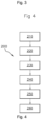
- the invention also relates to a method 200 for measuring the filling rate of the silo 110, as illustrated by FIG. [ Fig. 4 ].
- step 210 as explained above, the strain sensor 120 is provided.
- step 220 as explained above, the deformation sensor 120 is fixed on a single support foot 111 of the silo 110.
- step 230 as explained above, the first means of communication is provided.
- step 240 as explained above, the first means of communication is fixed to the support foot 111 of the silo 110.
- step 250 as explained above, the deformation sensor 120 is wired to the first means of communication.
- step 260 the remote server 140 is provided.
Landscapes
- Physics & Mathematics (AREA)
- General Physics & Mathematics (AREA)
- Fluid Mechanics (AREA)
- Engineering & Computer Science (AREA)
- Computer Networks & Wireless Communication (AREA)
- Arrangements For Transmission Of Measured Signals (AREA)
- Testing Or Calibration Of Command Recording Devices (AREA)
Claims (11)
- - System (100) zum Messen des Füllstands eines Silos (110) zum Lagern und Mischen von mindestens einem Schüttgut, wobei der Silo mit einer Vielzahl von Stützfüßen (111) am Boden versehen ist, das System umfassend:- einen einzelnen Verformungssensor (120), der bereitgestellt ist, um an einem einzelnen Stützfuß des Silos befestigt zu werden, sodass der Verformungssensor die Verformungen des Stützfußes als Reaktion auf das Einbringen oder Entnehmen des Schüttguts erfassen kann, wobei der Verformungssensor bereitgestellt ist, um die erfassten Verformungen in Verformungswerte umzuwandeln, und umfassend eine elektronische Schaltung (159) zum Erzeugen mindestens eines Messsignals, das die Verformungswerte umfasst, und zum Erzeugen mindestens eines Hilfssignals, das mit dem Messsignal assoziiert ist und das einen Zeitstempel der Verformungswerte umfasst,- eine erste drahtlose Kommunikationseinrichtung (130), das zum Emittieren des Messsignals und des Hilfssignals bereitgestellt ist, und- einen entfernten Server (140), der eine zweite drahtlose Kommunikationseinrichtung und einen Prozessor umfasst, wobei die zweite drahtlose Kommunikationseinrichtung bereitgestellt ist, um das Messsignal und das Hilfssignal zu empfangen, wobei der Prozessor bereitgestellt ist, um eine digitale Verarbeitung des Messsignals und des Hilfssignals durchzuführen, um eine Schätzung des Füllstands des Silos anhand eines mathematischen Gesetzes zu erlangen, das den Füllgrad des Silos und die Veränderung der Verformungswerte, die in dem Messsignal enthalten sind, miteinander verbindet, wobei das mathematische Gesetz anhand einer Vielzahl von Messsignalen und Hilfssignalen bestimmt wird.
- - System nach Anspruch 1, wobei der Verformungssensor einen Verbinder (160) umfasst, der elektrisch mit der elektronischen Schaltung verbunden ist, wobei der Verbinder bereitgestellt ist, um den Verformungssensor drahtgebunden mit der ersten drahtlosen Kommunikationseinrichtung zu verbinden.
- - System nach Anspruch 2, ferner umfassend einen Temperatursensor, der bereitgestellt ist, um mindestens eine Temperatur in der Nähe des Stützfußes des Silos zu messen, die Temperatur in einen Temperaturwert umzuwandeln und den Temperaturwert zu dem Messsignal hinzuzufügen.
- - System nach einem der Ansprüche 1 bis 3, ferner umfassend einen Geolokalisierungssensor, der bereitgestellt ist, um eine geografische Position des Verformungssensors zu bestimmen, die geografische Position in einen geografischen Positionswert umzuwandeln und den geografischen Positionswert zu dem Hilfssignal hinzuzufügen.
- - System nach einem der Ansprüche 1 bis 4, wobei der Prozessor den Füllstand des Silos ferner abhängig von einer Änderungsgeschwindigkeit der erfassten Verformungswerte bestimmt.
- - System nach einem der Ansprüche 1 bis 5, wobei die digitale Verarbeitung des Messsignals und des Hilfssignals durch einen Prozessor die Bestimmung eines Satzes von Korrekturparametern umfasst, die es ermöglichen, die Auswirkung der Temperatur auf den Stützfuß des Silos und die Auswirkung der Zeit auf die Erfassungsleistung des Verformungssensors zu berücksichtigen.
- - System nach einem der Ansprüche 1 bis 6, wobei der Verformungssensor einen Prüfkörper (150) aufweist, der zwei Endabschnitte (151, 152) umfasst, durch die der Prüfkörper an dem Stützfuß des Silos befestigt werden kann.
- - System nach Anspruch 7, wobei der Verformungssensor durch Schrauben an dem Stützfuß des Silos befestigt ist.
- - System nach einem der Ansprüche 1 bis 8, wobei der Verformungssensor durch Klebstoff an dem Stützfuß des Silos befestigt ist.
- - System nach einem der Ansprüche 1 bis 9, ferner umfassend ein Gehäuse (170), das bereitgestellt ist, um einen Mittelabschnitt des Prüfkörpers und den Verbinder zu umschließen, wobei der Verbinder aus dem Gehäuse hervorsteht.
- - Verfahren (200) zum Messen des Füllstands eines Silos (110) zum Lagern und Mischen von mindestens einem Schüttgut, wobei der Silo mit einer Vielzahl von Stützfüßen (111) am Boden versehen ist, das Verfahren umfassend:- einen ersten Schritt eines Lieferns (210) eines einzelnen Verformungssensors (120), der bereitgestellt ist, um an einem einzelnen Stützfuß des Silos befestigt zu werden, sodass der Verformungssensor die Verformungen des Stützfußes als Reaktion auf das Einbringen oder Entnehmen des Schüttguts erfassen kann, wobei der Verformungssensor bereitgestellt ist, um die erfassten Verformungen in Verformungswerte umzuwandeln, und umfassend eine elektronische Schaltung (159) zum Erzeugen mindestens eines Messsignals, das die Verformungswerte umfasst, und zum Erzeugen mindestens eines Hilfssignals, das mit dem Messsignal assoziiert ist und das einen Zeitstempel der Verformungswerte umfasst,- einen ersten Schritt eines Befestigens (220) des Verformungssensors an dem Stützfuß des Silos,- einen zweiten Schritt eines Lieferns (230) einer ersten drahtlosen Kommunikationseinrichtung (130), das zum Senden des Messsignals und des Hilfssignals bereitgestellt ist, und- einen zweiten Schritt eines Befestigens (240) der ersten drahtlosen Kommunikationseinrichtung an dem Stützfuß des Silos,- einen Schritt eines drahtgebundenen Verbindens (250) des Verformungssensors mit der ersten Kommunikationseinrichtung, und- einen dritten Schritt eines Lieferns (260) eines entfernten Servers (140), der eine zweite drahtlose Kommunikationseinrichtung und einen Prozessor umfasst, wobei die zweite drahtlose Kommunikationseinrichtung bereitgestellt ist, um das Messsignal und das Hilfssignal zu empfangen, wobei der Prozessor bereitgestellt ist, um eine digitale Verarbeitung des Messsignals und des Hilfssignals durchzuführen, um eine Schätzung des Füllstands des Silos anhand eines mathematischen Gesetzes zu erlangen, das den Füllgrad des Silos und die Veränderung der Verformungswerte, die in dem Messsignal enthalten sind, miteinander verbindet, wobei das mathematische Gesetz anhand einer Vielzahl von Messsignalen und Hilfssignalen bestimmt wird.
Applications Claiming Priority (2)
| Application Number | Priority Date | Filing Date | Title |
|---|---|---|---|
| FR1904594A FR3095696B1 (fr) | 2019-04-30 | 2019-04-30 | Systèmes et procédés de mesure du niveau de remplissage d’un silo |
| PCT/EP2020/062024 WO2020221857A1 (fr) | 2019-04-30 | 2020-04-30 | Systèmes et procédés de mesure du niveau de remplissage d'un silo |
Publications (4)
| Publication Number | Publication Date |
|---|---|
| EP3963296A1 EP3963296A1 (de) | 2022-03-09 |
| EP3963296B1 true EP3963296B1 (de) | 2024-10-09 |
| EP3963296C0 EP3963296C0 (de) | 2024-10-09 |
| EP3963296B8 EP3963296B8 (de) | 2024-11-13 |
Family
ID=67262754
Family Applications (1)
| Application Number | Title | Priority Date | Filing Date |
|---|---|---|---|
| EP20721616.9A Active EP3963296B8 (de) | 2019-04-30 | 2020-04-30 | Systeme und verfahren zur füllstandsmessung eines silos |
Country Status (7)
| Country | Link |
|---|---|
| US (1) | US11920969B2 (de) |
| EP (1) | EP3963296B8 (de) |
| CA (1) | CA3132523C (de) |
| ES (1) | ES2996920T3 (de) |
| FR (1) | FR3095696B1 (de) |
| PL (1) | PL3963296T3 (de) |
| WO (1) | WO2020221857A1 (de) |
Cited By (1)
| Publication number | Priority date | Publication date | Assignee | Title |
|---|---|---|---|---|
| FR3165311A1 (fr) | 2025-03-07 | 2026-02-06 | Nanolike | Système de traitement de mesures de déformation d’un pied d’appui de silo pour l'isolement de la composante de déformation liee au poids du contenant silo par apprentissage automatique |
Families Citing this family (2)
| Publication number | Priority date | Publication date | Assignee | Title |
|---|---|---|---|---|
| FR3095696B1 (fr) | 2019-04-30 | 2021-05-14 | Nanolike | Systèmes et procédés de mesure du niveau de remplissage d’un silo |
| FR3160399B1 (fr) | 2024-03-22 | 2026-02-13 | Nanolike | Système de détection du transfert d’un silo transportable d’un premier site d’exploitation vers un deuxième site d’exploitation |
Citations (14)
| Publication number | Priority date | Publication date | Assignee | Title |
|---|---|---|---|---|
| US4064744A (en) | 1976-06-04 | 1977-12-27 | Kistler-Morse Corporation | Strain sensorextensiometer |
| JPH09236479A (ja) * | 1996-03-01 | 1997-09-09 | Shoei Denki Kk | 歪ゲージを用いた重量センサの構造 |
| US5983198A (en) | 1996-04-23 | 1999-11-09 | Novus International, Inc. | Integrated system monitoring use of materials, controlling and monitoring delivery of materials and providing automated billing of delivered materials |
| DE10018942A1 (de) | 2000-04-17 | 2001-10-18 | Cargocom Gmbh | Verfahren zur telemetrischen Ermittlung der sich bei einem Lastkraftwagen ergebenden Gewichtsstrecke |
| CA2371068A1 (en) | 2002-02-08 | 2003-08-08 | Bill Christensen | Load sensor |
| ES1062520U (es) * | 2006-03-13 | 2006-07-01 | Dinacell Electronica Sl | Sensor de carga con sonda de temperatura incorporada. |
| WO2006105679A1 (de) * | 2005-04-08 | 2006-10-12 | Digi Sens Ag | Silowaage |
| US20070135955A1 (en) | 1998-10-06 | 2007-06-14 | J.P. Donmoyer, Inc. | Bulk inventory network system |
| WO2008037095A1 (de) | 2006-09-29 | 2008-04-03 | Digi Sens Ag | Silowaage |
| CN202025205U (zh) | 2011-03-04 | 2011-11-02 | 福建南方路面机械有限公司 | 料仓料位在线智能监测系统 |
| US8581734B2 (en) | 2010-01-11 | 2013-11-12 | Antonio Ozamiz Tapia | Management system for managing bulk material inside a silo using a set of load cells and an accelerometer |
| US20160236902A1 (en) * | 2013-09-23 | 2016-08-18 | Dinacell Electrónica, S.L. | Method and arrangement for calibrating the load control system of a lift |
| WO2018039787A1 (en) * | 2016-08-29 | 2018-03-08 | Technologies Intelia Inc. | Method and apparatus to monitor a reservoir or a structure |
| CN109178966A (zh) * | 2018-07-20 | 2019-01-11 | 芜湖佩林郁松计量科技有限公司 | 一种玉米入仓称重计量设备 |
Family Cites Families (11)
| Publication number | Priority date | Publication date | Assignee | Title |
|---|---|---|---|---|
| US5493903A (en) * | 1994-08-23 | 1996-02-27 | Allen; James | Method of determining the volume of a substance having a density, in vertical storage tanks |
| US6513373B1 (en) * | 2001-12-21 | 2003-02-04 | Grand Hall Enterprise Co., Ltd. | Suspension support with volume indication for a LPG tank |
| US6636820B2 (en) * | 2002-02-20 | 2003-10-21 | Becs Technology, Inc. | Method and apparatus for measuring weight using uncalibrated load cells |
| US20050284381A1 (en) * | 2004-06-04 | 2005-12-29 | Bell Timothy L | Livestock facility equipment network |
| US7255003B2 (en) * | 2005-09-12 | 2007-08-14 | Schneiter Calvin R | Device for measuring and displaying the amount of beer in a keg |
| US8444312B2 (en) * | 2009-09-11 | 2013-05-21 | Halliburton Energy Services, Inc. | Methods and systems for integral blending and storage of materials |
| US10300830B2 (en) * | 2011-10-24 | 2019-05-28 | Solaris Oilfield Site Services Operating Llc | Storage and blending system for multi-component granular compositions |
| US9360360B2 (en) * | 2012-12-06 | 2016-06-07 | Osborne Industries Inc. | System for measuring level of dry bulk material in container |
| WO2017137832A1 (en) * | 2016-02-11 | 2017-08-17 | Ubikwa Systems, Slu | A method and a system for assessing the amount of content stored within a container |
| KR20190043573A (ko) * | 2016-09-09 | 2019-04-26 | 가부시키가이샤 네지로 | 센서 구조, 센서 구조 부착 부재, 센서 구조의 패터닝 방법 |
| FR3095696B1 (fr) | 2019-04-30 | 2021-05-14 | Nanolike | Systèmes et procédés de mesure du niveau de remplissage d’un silo |
-
2019
- 2019-04-30 FR FR1904594A patent/FR3095696B1/fr active Active
-
2020
- 2020-04-30 US US17/605,425 patent/US11920969B2/en active Active
- 2020-04-30 CA CA3132523A patent/CA3132523C/fr active Active
- 2020-04-30 ES ES20721616T patent/ES2996920T3/es active Active
- 2020-04-30 EP EP20721616.9A patent/EP3963296B8/de active Active
- 2020-04-30 WO PCT/EP2020/062024 patent/WO2020221857A1/fr not_active Ceased
- 2020-04-30 PL PL20721616.9T patent/PL3963296T3/pl unknown
Patent Citations (15)
| Publication number | Priority date | Publication date | Assignee | Title |
|---|---|---|---|---|
| US4064744B1 (de) | 1976-06-04 | 1985-12-17 | ||
| US4064744A (en) | 1976-06-04 | 1977-12-27 | Kistler-Morse Corporation | Strain sensorextensiometer |
| JPH09236479A (ja) * | 1996-03-01 | 1997-09-09 | Shoei Denki Kk | 歪ゲージを用いた重量センサの構造 |
| US5983198A (en) | 1996-04-23 | 1999-11-09 | Novus International, Inc. | Integrated system monitoring use of materials, controlling and monitoring delivery of materials and providing automated billing of delivered materials |
| US20070135955A1 (en) | 1998-10-06 | 2007-06-14 | J.P. Donmoyer, Inc. | Bulk inventory network system |
| DE10018942A1 (de) | 2000-04-17 | 2001-10-18 | Cargocom Gmbh | Verfahren zur telemetrischen Ermittlung der sich bei einem Lastkraftwagen ergebenden Gewichtsstrecke |
| CA2371068A1 (en) | 2002-02-08 | 2003-08-08 | Bill Christensen | Load sensor |
| WO2006105679A1 (de) * | 2005-04-08 | 2006-10-12 | Digi Sens Ag | Silowaage |
| ES1062520U (es) * | 2006-03-13 | 2006-07-01 | Dinacell Electronica Sl | Sensor de carga con sonda de temperatura incorporada. |
| WO2008037095A1 (de) | 2006-09-29 | 2008-04-03 | Digi Sens Ag | Silowaage |
| US8581734B2 (en) | 2010-01-11 | 2013-11-12 | Antonio Ozamiz Tapia | Management system for managing bulk material inside a silo using a set of load cells and an accelerometer |
| CN202025205U (zh) | 2011-03-04 | 2011-11-02 | 福建南方路面机械有限公司 | 料仓料位在线智能监测系统 |
| US20160236902A1 (en) * | 2013-09-23 | 2016-08-18 | Dinacell Electrónica, S.L. | Method and arrangement for calibrating the load control system of a lift |
| WO2018039787A1 (en) * | 2016-08-29 | 2018-03-08 | Technologies Intelia Inc. | Method and apparatus to monitor a reservoir or a structure |
| CN109178966A (zh) * | 2018-07-20 | 2019-01-11 | 芜湖佩林郁松计量科技有限公司 | 一种玉米入仓称重计量设备 |
Non-Patent Citations (14)
| Title |
|---|
| ANDROIDANDYUK: "Budget Digital Bluetooth Body Fat Smart Scales", 8 October 2018 (2018-10-08), XP093278498, Retrieved from the Internet <URL:https://www.youtube.com/watch?v=NL7lopb72CE> |
| ANONYMOUS: "Cloud computing ", WIKIPEDIA, 6 May 2025 (2025-05-06), XP093278493, Retrieved from the Internet <URL:https://en.wikipedia.org/w/index.php?title=Cloud_computing&oldid=1289095428> |
| ANONYMOUS: "GP2Y0A41SK0F distance sensor datasheet", POLOLU, 1 August 2013 (2013-08-01), pages 1 - 8, XP093020980, Retrieved from the Internet <URL:https://www.pololu.com/file/0J713/GP2Y0A41SK0F.pdf> [retrieved on 20230206] * |
| ANONYMOUS: "IVQs in Electrical and Electronic Engineering", CITY & GUILDS, 1 September 2009 (2009-09-01), pages 1 - 96, XP093020967, Retrieved from the Internet <URL:https://cdn.cityandguilds.com/productdocuments/engineering/electrical_and_electronic/8030/8030_level_2/centre_documents/8030-200_l2_qualification_handbook_v1.pdf> [retrieved on 20230206] * |
| ANONYMOUS: "OM-DAQXL Multi-Channel Universal Input Touch Screen Data Logger", INSTRUMENTATION.COM, 1 January 2017 (2017-01-01), pages 1 - 85, XP093020999, Retrieved from the Internet <URL:https://instrumentation.com/pdfs/M5570.pdf> [retrieved on 20230206] * |
| ANONYMOUS: "Remote Desktop Protocol", WIKIPEDIA, 4 May 2025 (2025-05-04), XP093278495, Retrieved from the Internet <URL:https://en.wikipedia.org/w/index.php?title=Remote_Desktop_Protocol&oldid=1288696588> |
| ANONYMOUS: "Sensor por deformación SD1000", DINACELL - FICHA TÉCNICA, 28 February 2018 (2018-02-28), XP055883222, Retrieved from the Internet <URL:http://www.dinacell.com/> [retrieved on 20220125] * |
| ANONYMOUS: "Silo Weight Monitoring and Control", SCALE-TRON INC., 12 June 2014 (2014-06-12), pages 1 - 6, XP093021016, Retrieved from the Internet <URL:https://www.environmental-expert.com/downloads/siloweigh-silex-sensor-installation-user-manual-416115?callBackMethodJs=openFlipbook> [retrieved on 20230206] * |
| ANONYMOUS: "SiloWeigh - Silex Sensor Installation User Manual", AYSIX TECHNOLOGIES / USER'S MANUAL, 1 September 2011 (2011-09-01), XP055883228, Retrieved from the Internet <URL:https://www.environmental-expert.com/downloads/siloweigh-silex-sensor-installation-user-manual-416115?callBackMethodJs=openFlipbook> [retrieved on 20220125] * |
| ANONYMOUS: "The StrainCell 360° strain sensor to a weighing of silos and industrial facilities afterwards", STRAIN SYSTEM EUROPE - FLYER, 1 January 2014 (2014-01-01), XP055883217, Retrieved from the Internet <URL:http://www.strainsystems.eu/english/media/StrainCell-Flyer-k.pdf> [retrieved on 20220125] * |
| ANONYMOUS: "Transductor de fuerza DF30/RF", DINACELL - FICHA TÉCNICA, 14 September 2018 (2018-09-14), XP055883214, Retrieved from the Internet <URL:http://www.dinacell.com/> [retrieved on 20220125] * |
| ANONYMOUS: "VersaLog brochure", ACCSENSE.COM, 19 June 2015 (2015-06-19), pages 1 - 2, XP093021020, Retrieved from the Internet <URL:https://accsense.com/wp-content/uploads/2018/07/VersaLog-BR-2.pdf> [retrieved on 20230206] * |
| YOUTUBE VIDEO - "INTEGRATED TEST & MEASUREMENT (ITM) SOLO MONITORING DEMO" PUBLISHED 14 AUGUST 2014 (CANNOT BE FOUND ON INTERNET) |
| YOUTUBE VIDEO "WIFI & BLUETOOTH BATHROOM SCALES" PUBLISHED 12 MARCH 2017 (CANNOT BE FOUND ON INTERNET) |
Cited By (1)
| Publication number | Priority date | Publication date | Assignee | Title |
|---|---|---|---|---|
| FR3165311A1 (fr) | 2025-03-07 | 2026-02-06 | Nanolike | Système de traitement de mesures de déformation d’un pied d’appui de silo pour l'isolement de la composante de déformation liee au poids du contenant silo par apprentissage automatique |
Also Published As
| Publication number | Publication date |
|---|---|
| CA3132523C (fr) | 2024-04-16 |
| EP3963296B8 (de) | 2024-11-13 |
| PL3963296T3 (pl) | 2025-01-07 |
| FR3095696A1 (fr) | 2020-11-06 |
| ES2996920T3 (en) | 2025-02-13 |
| US11920969B2 (en) | 2024-03-05 |
| FR3095696B1 (fr) | 2021-05-14 |
| EP3963296C0 (de) | 2024-10-09 |
| WO2020221857A1 (fr) | 2020-11-05 |
| US20220187116A1 (en) | 2022-06-16 |
| EP3963296A1 (de) | 2022-03-09 |
| CA3132523A1 (fr) | 2020-11-05 |
Similar Documents
| Publication | Publication Date | Title |
|---|---|---|
| EP3963296B1 (de) | Systeme und verfahren zur füllstandsmessung eines silos | |
| EP2921863B1 (de) | Verfahren und Vorrichtung zum automatischen Abschätzen von Flugparametern eines Luftfahrzeugs | |
| FR2901357A1 (fr) | Dispositif de detection d'angle de rotation permettant une mesure du degre de rotation d'un arbre qui depasse 360 | |
| EP3209993B1 (de) | Verfahren und vorrichtung zur überwachung von einer flugzeugsturbineschaufel durch messung einer gleichgewichtposition | |
| FR3003346A1 (fr) | Capteur a fibre optique | |
| FR2918743A1 (fr) | Capteur d'attitude a quartz piezoelectrique | |
| WO2006013247A1 (fr) | Dispositif optique de mesure de l’epaisseur d’un milieu au moins partiellement transparent | |
| EP3449208A1 (de) | Vorrichtung zur messung von endogenen deformationen | |
| EP2864756A1 (de) | Verfahren zur bestimmung der grössenverteilung eines gemisches von teilchen mit taylor-dispersion und zugehöriges system | |
| EP3870522A1 (de) | Vorrichtung zum lagern von mindestens einem schüttgut | |
| EP1963779B1 (de) | Vorrichtung zur aufnahme einer lagerung mit einem system zur erkennung der auf die lagerung gelegten last. | |
| FR3125875A1 (fr) | Procédé de mesure non intrusive de la variation de pression interne et/ou de variation de température d’un tuyau, dispositif de mesure et installation associés | |
| EP1642095A2 (de) | Elektromagnetischer schleifensensor zur messung von einer strasse durch strassenverkehr auferlegten dynamischen lasten | |
| FR2874085A1 (fr) | Systeme et procede pour ameliorer la mesure de proprietes rheologiques | |
| FR3022291B1 (fr) | Raidisseur de courbure pour un element allonge destine a etre introduit dans une etendue d'eau | |
| FR3096775A1 (fr) | Dispositif de mesures capacitives d’une hauteur d’un fluide dans un réservoir | |
| WO2018219683A1 (fr) | Capteur de déformation monobloc et procédé de mesure de la déformation d'une surface d'un solide | |
| EP3725099B1 (de) | Verfahren zur erkennung einer fehlfunktion eines mit einem elektrochemischen generator gekoppelten akustischen sensors und vorrichtung zur durchführung des verfahrens | |
| EP4646579B1 (de) | System zur erkennung des umschlags eines transportfähigen silos von einem ersten arbeitsplatz zu einem zweiten arbeitsplatz | |
| FR3116336A1 (fr) | Procédé de traitement d’un signal de mesure pour obtenir une signature et dispositif de mesure associé | |
| FR2701566A1 (fr) | Procédé de mesure d'au moins une caractéristique d'une solution liquide et moyens pour la mise en Óoeuvre de la dite solution. | |
| EP2496916A1 (de) | Vorrichtung zur bestimmung des gewichts eines objekts | |
| WO2008006973A1 (fr) | Dispositif de mesure de propriétés électriques d'un milieu comportant de l'eau | |
| Gonchar et al. | THE INCREASE OF THE ACCURACY OF SOLID AND LIQUID TRANSPARENT FILMS THICKNESS MEASUREMENT | |
| FR2660430A1 (fr) | Appareil et procede pour la mesure d'une grandeur mecanique telle qu'une force ou un moment. |
Legal Events
| Date | Code | Title | Description |
|---|---|---|---|
| STAA | Information on the status of an ep patent application or granted ep patent |
Free format text: STATUS: UNKNOWN |
|
| STAA | Information on the status of an ep patent application or granted ep patent |
Free format text: STATUS: THE INTERNATIONAL PUBLICATION HAS BEEN MADE |
|
| TPAC | Observations filed by third parties |
Free format text: ORIGINAL CODE: EPIDOSNTIPA |
|
| PUAI | Public reference made under article 153(3) epc to a published international application that has entered the european phase |
Free format text: ORIGINAL CODE: 0009012 |
|
| STAA | Information on the status of an ep patent application or granted ep patent |
Free format text: STATUS: REQUEST FOR EXAMINATION WAS MADE |
|
| 17P | Request for examination filed |
Effective date: 20211027 |
|
| AK | Designated contracting states |
Kind code of ref document: A1 Designated state(s): AL AT BE BG CH CY CZ DE DK EE ES FI FR GB GR HR HU IE IS IT LI LT LU LV MC MK MT NL NO PL PT RO RS SE SI SK SM TR |
|
| DAV | Request for validation of the european patent (deleted) | ||
| DAX | Request for extension of the european patent (deleted) | ||
| TPAC | Observations filed by third parties |
Free format text: ORIGINAL CODE: EPIDOSNTIPA |
|
| TPAC | Observations filed by third parties |
Free format text: ORIGINAL CODE: EPIDOSNTIPA |
|
| STAA | Information on the status of an ep patent application or granted ep patent |
Free format text: STATUS: EXAMINATION IS IN PROGRESS |
|
| 17Q | First examination report despatched |
Effective date: 20231016 |
|
| GRAP | Despatch of communication of intention to grant a patent |
Free format text: ORIGINAL CODE: EPIDOSNIGR1 |
|
| STAA | Information on the status of an ep patent application or granted ep patent |
Free format text: STATUS: GRANT OF PATENT IS INTENDED |
|
| INTG | Intention to grant announced |
Effective date: 20240718 |
|
| RAP3 | Party data changed (applicant data changed or rights of an application transferred) |
Owner name: NANOLIKE |
|
| GRAS | Grant fee paid |
Free format text: ORIGINAL CODE: EPIDOSNIGR3 |
|
| GRAA | (expected) grant |
Free format text: ORIGINAL CODE: 0009210 |
|
| STAA | Information on the status of an ep patent application or granted ep patent |
Free format text: STATUS: THE PATENT HAS BEEN GRANTED |
|
| REG | Reference to a national code |
Ref country code: DE Ref legal event code: R081 Ref document number: 602020039031 Country of ref document: DE Owner name: NANOLIKE, FR Free format text: FORMER OWNER: NANOLIKE, LABEGE, FR |
|
| AK | Designated contracting states |
Kind code of ref document: B1 Designated state(s): AL AT BE BG CH CY CZ DE DK EE ES FI FR GB GR HR HU IE IS IT LI LT LU LV MC MK MT NL NO PL PT RO RS SE SI SK SM TR |
|
| REG | Reference to a national code |
Ref country code: CH Ref legal event code: EP |
|
| RAP4 | Party data changed (patent owner data changed or rights of a patent transferred) |
Owner name: NANOLIKE |
|
| REG | Reference to a national code |
Ref country code: DE Ref legal event code: R096 Ref document number: 602020039031 Country of ref document: DE |
|
| REG | Reference to a national code |
Ref country code: CH Ref legal event code: PK Free format text: RECTIFICATION B8 |
|
| REG | Reference to a national code |
Ref country code: IE Ref legal event code: FG4D Free format text: LANGUAGE OF EP DOCUMENT: FRENCH |
|
| U01 | Request for unitary effect filed |
Effective date: 20241009 |
|
| U07 | Unitary effect registered |
Designated state(s): AT BE BG DE DK EE FI FR IT LT LU LV MT NL PT RO SE SI Effective date: 20241028 |
|
| REG | Reference to a national code |
Ref country code: DE Ref legal event code: R026 Ref document number: 602020039031 Country of ref document: DE |
|
| PLBI | Opposition filed |
Free format text: ORIGINAL CODE: 0009260 |
|
| 26 | Opposition filed |
Opponent name: DINACELL ELECTRONICA, S.L. Effective date: 20241205 |
|
| REG | Reference to a national code |
Ref country code: ES Ref legal event code: FG2A Ref document number: 2996920 Country of ref document: ES Kind code of ref document: T3 Effective date: 20250213 |
|
| U1N | Appointed representative for the unitary patent procedure changed after the registration of the unitary effect |
Representative=s name: A.P.I. CONSEIL; FR |
|
| PG25 | Lapsed in a contracting state [announced via postgrant information from national office to epo] |
Ref country code: HR Free format text: LAPSE BECAUSE OF FAILURE TO SUBMIT A TRANSLATION OF THE DESCRIPTION OR TO PAY THE FEE WITHIN THE PRESCRIBED TIME-LIMIT Effective date: 20241009 Ref country code: IS Free format text: LAPSE BECAUSE OF FAILURE TO SUBMIT A TRANSLATION OF THE DESCRIPTION OR TO PAY THE FEE WITHIN THE PRESCRIBED TIME-LIMIT Effective date: 20250209 |
|
| PG25 | Lapsed in a contracting state [announced via postgrant information from national office to epo] |
Ref country code: GR Free format text: LAPSE BECAUSE OF FAILURE TO SUBMIT A TRANSLATION OF THE DESCRIPTION OR TO PAY THE FEE WITHIN THE PRESCRIBED TIME-LIMIT Effective date: 20250110 |
|
| PG25 | Lapsed in a contracting state [announced via postgrant information from national office to epo] |
Ref country code: RS Free format text: LAPSE BECAUSE OF FAILURE TO SUBMIT A TRANSLATION OF THE DESCRIPTION OR TO PAY THE FEE WITHIN THE PRESCRIBED TIME-LIMIT Effective date: 20250109 |
|
| PLBI | Opposition filed |
Free format text: ORIGINAL CODE: 0009260 |
|
| PLAB | Opposition data, opponent's data or that of the opponent's representative modified |
Free format text: ORIGINAL CODE: 0009299OPPO |
|
| U20 | Renewal fee for the european patent with unitary effect paid |
Year of fee payment: 6 Effective date: 20250428 |
|
| 26 | Opposition filed |
Opponent name: E COLLINSON & CO. LTD. Effective date: 20250507 |
|
| R26 | Opposition filed (corrected) |
Opponent name: E COLLINSON & CO. LTD. Effective date: 20250507 |
|
| PG25 | Lapsed in a contracting state [announced via postgrant information from national office to epo] |
Ref country code: SM Free format text: LAPSE BECAUSE OF FAILURE TO SUBMIT A TRANSLATION OF THE DESCRIPTION OR TO PAY THE FEE WITHIN THE PRESCRIBED TIME-LIMIT Effective date: 20241009 |
|
| PGFP | Annual fee paid to national office [announced via postgrant information from national office to epo] |
Ref country code: PL Payment date: 20250429 Year of fee payment: 6 |
|
| PGFP | Annual fee paid to national office [announced via postgrant information from national office to epo] |
Ref country code: GB Payment date: 20250423 Year of fee payment: 6 Ref country code: ES Payment date: 20250506 Year of fee payment: 6 |
|
| PGFP | Annual fee paid to national office [announced via postgrant information from national office to epo] |
Ref country code: NO Payment date: 20250424 Year of fee payment: 6 |
|
| PGFP | Annual fee paid to national office [announced via postgrant information from national office to epo] |
Ref country code: CH Payment date: 20250501 Year of fee payment: 6 |
|
| PLAX | Notice of opposition and request to file observation + time limit sent |
Free format text: ORIGINAL CODE: EPIDOSNOBS2 |
|
| PG25 | Lapsed in a contracting state [announced via postgrant information from national office to epo] |
Ref country code: SK Free format text: LAPSE BECAUSE OF FAILURE TO SUBMIT A TRANSLATION OF THE DESCRIPTION OR TO PAY THE FEE WITHIN THE PRESCRIBED TIME-LIMIT Effective date: 20241009 |
|
| PGFP | Annual fee paid to national office [announced via postgrant information from national office to epo] |
Ref country code: TR Payment date: 20250416 Year of fee payment: 6 |
|
| PG25 | Lapsed in a contracting state [announced via postgrant information from national office to epo] |
Ref country code: CZ Free format text: LAPSE BECAUSE OF FAILURE TO SUBMIT A TRANSLATION OF THE DESCRIPTION OR TO PAY THE FEE WITHIN THE PRESCRIBED TIME-LIMIT Effective date: 20241009 |
|
| PGFP | Annual fee paid to national office [announced via postgrant information from national office to epo] |
Ref country code: IE Payment date: 20250428 Year of fee payment: 6 |
|
| PLBB | Reply of patent proprietor to notice(s) of opposition received |
Free format text: ORIGINAL CODE: EPIDOSNOBS3 |
|
| PG25 | Lapsed in a contracting state [announced via postgrant information from national office to epo] |
Ref country code: MC Free format text: LAPSE BECAUSE OF FAILURE TO SUBMIT A TRANSLATION OF THE DESCRIPTION OR TO PAY THE FEE WITHIN THE PRESCRIBED TIME-LIMIT Effective date: 20241009 |