EP3963247B1 - Shielding structure - Google Patents
Shielding structure Download PDFInfo
- Publication number
- EP3963247B1 EP3963247B1 EP20735269.1A EP20735269A EP3963247B1 EP 3963247 B1 EP3963247 B1 EP 3963247B1 EP 20735269 A EP20735269 A EP 20735269A EP 3963247 B1 EP3963247 B1 EP 3963247B1
- Authority
- EP
- European Patent Office
- Prior art keywords
- shielding structure
- elements
- sheet
- strips
- sections
- Prior art date
- Legal status (The legal status is an assumption and is not a legal conclusion. Google has not performed a legal analysis and makes no representation as to the accuracy of the status listed.)
- Active
Links
- 239000002184 metal Substances 0.000 claims description 36
- 229910052751 metal Inorganic materials 0.000 claims description 36
- 238000004080 punching Methods 0.000 claims description 13
- 238000005520 cutting process Methods 0.000 claims description 4
- 230000002441 reversible effect Effects 0.000 claims description 4
- 238000013016 damping Methods 0.000 claims description 3
- 238000012545 processing Methods 0.000 claims description 3
- 230000007704 transition Effects 0.000 claims description 3
- 238000003466 welding Methods 0.000 claims description 3
- 230000008859 change Effects 0.000 description 9
- 230000000694 effects Effects 0.000 description 9
- 230000004048 modification Effects 0.000 description 7
- 238000012986 modification Methods 0.000 description 7
- 150000002739 metals Chemical class 0.000 description 5
- 238000002485 combustion reaction Methods 0.000 description 4
- 230000005855 radiation Effects 0.000 description 4
- 230000017525 heat dissipation Effects 0.000 description 3
- 238000009413 insulation Methods 0.000 description 3
- 230000000750 progressive effect Effects 0.000 description 3
- 229910000831 Steel Inorganic materials 0.000 description 2
- 238000004026 adhesive bonding Methods 0.000 description 2
- 229910045601 alloy Inorganic materials 0.000 description 2
- 239000000956 alloy Substances 0.000 description 2
- 239000011324 bead Substances 0.000 description 2
- 238000013461 design Methods 0.000 description 2
- 238000001125 extrusion Methods 0.000 description 2
- 230000006870 function Effects 0.000 description 2
- 239000011810 insulating material Substances 0.000 description 2
- 238000004519 manufacturing process Methods 0.000 description 2
- 239000000463 material Substances 0.000 description 2
- 239000010959 steel Substances 0.000 description 2
- 229910001369 Brass Inorganic materials 0.000 description 1
- 229910001374 Invar Inorganic materials 0.000 description 1
- HCHKCACWOHOZIP-UHFFFAOYSA-N Zinc Chemical compound [Zn] HCHKCACWOHOZIP-UHFFFAOYSA-N 0.000 description 1
- 230000003321 amplification Effects 0.000 description 1
- 238000000137 annealing Methods 0.000 description 1
- 238000005452 bending Methods 0.000 description 1
- 230000015572 biosynthetic process Effects 0.000 description 1
- 239000010951 brass Substances 0.000 description 1
- 150000001875 compounds Chemical class 0.000 description 1
- 238000001816 cooling Methods 0.000 description 1
- 230000001419 dependent effect Effects 0.000 description 1
- 238000011161 development Methods 0.000 description 1
- 238000009792 diffusion process Methods 0.000 description 1
- 238000005553 drilling Methods 0.000 description 1
- 239000003822 epoxy resin Substances 0.000 description 1
- 238000005530 etching Methods 0.000 description 1
- 230000005284 excitation Effects 0.000 description 1
- 230000002349 favourable effect Effects 0.000 description 1
- 238000010438 heat treatment Methods 0.000 description 1
- 238000000034 method Methods 0.000 description 1
- 238000003199 nucleic acid amplification method Methods 0.000 description 1
- 230000008447 perception Effects 0.000 description 1
- 229920000647 polyepoxide Polymers 0.000 description 1
- 230000008569 process Effects 0.000 description 1
- 238000005096 rolling process Methods 0.000 description 1
- 238000007493 shaping process Methods 0.000 description 1
- 230000002277 temperature effect Effects 0.000 description 1
- 238000012549 training Methods 0.000 description 1
- XLYOFNOQVPJJNP-UHFFFAOYSA-N water Substances O XLYOFNOQVPJJNP-UHFFFAOYSA-N 0.000 description 1
- 229910052725 zinc Inorganic materials 0.000 description 1
- 239000011701 zinc Substances 0.000 description 1
Images

Classifications
-
- F—MECHANICAL ENGINEERING; LIGHTING; HEATING; WEAPONS; BLASTING
- F16—ENGINEERING ELEMENTS AND UNITS; GENERAL MEASURES FOR PRODUCING AND MAINTAINING EFFECTIVE FUNCTIONING OF MACHINES OR INSTALLATIONS; THERMAL INSULATION IN GENERAL
- F16L—PIPES; JOINTS OR FITTINGS FOR PIPES; SUPPORTS FOR PIPES, CABLES OR PROTECTIVE TUBING; MEANS FOR THERMAL INSULATION IN GENERAL
- F16L55/00—Devices or appurtenances for use in, or in connection with, pipes or pipe systems
- F16L55/02—Energy absorbers; Noise absorbers
- F16L55/033—Noise absorbers
-
- B—PERFORMING OPERATIONS; TRANSPORTING
- B60—VEHICLES IN GENERAL
- B60R—VEHICLES, VEHICLE FITTINGS, OR VEHICLE PARTS, NOT OTHERWISE PROVIDED FOR
- B60R13/00—Elements for body-finishing, identifying, or decorating; Arrangements or adaptations for advertising purposes
- B60R13/08—Insulating elements, e.g. for sound insulation
- B60R13/0876—Insulating elements, e.g. for sound insulation for mounting around heat sources, e.g. exhaust pipes
-
- F—MECHANICAL ENGINEERING; LIGHTING; HEATING; WEAPONS; BLASTING
- F02—COMBUSTION ENGINES; HOT-GAS OR COMBUSTION-PRODUCT ENGINE PLANTS
- F02B—INTERNAL-COMBUSTION PISTON ENGINES; COMBUSTION ENGINES IN GENERAL
- F02B77/00—Component parts, details or accessories, not otherwise provided for
- F02B77/11—Thermal or acoustic insulation
-
- F—MECHANICAL ENGINEERING; LIGHTING; HEATING; WEAPONS; BLASTING
- F16—ENGINEERING ELEMENTS AND UNITS; GENERAL MEASURES FOR PRODUCING AND MAINTAINING EFFECTIVE FUNCTIONING OF MACHINES OR INSTALLATIONS; THERMAL INSULATION IN GENERAL
- F16L—PIPES; JOINTS OR FITTINGS FOR PIPES; SUPPORTS FOR PIPES, CABLES OR PROTECTIVE TUBING; MEANS FOR THERMAL INSULATION IN GENERAL
- F16L59/00—Thermal insulation in general
- F16L59/08—Means for preventing radiation, e.g. with metal foil
Definitions
- the present invention relates to a shielding structure for shielding an object against heat and/or sound, the shielding structure having an inner surface facing the object and an outer surface facing away from the object.
- shielding structures are known from the prior art, for example as heat shields. Shielding structures are also known which, in addition to thermal insulation, also have acoustic insulation. The acoustic effectiveness of shielding structures can be achieved by introducing insulating material and can be further enhanced in combination with open-pored sheet metal layers facing sound. In other frequency ranges, however, a higher rigidity of a shielding structure is desired in order to reduce sound radiation. Greater mechanical rigidity is achieved by introducing structures, such as beads, in acoustically relevant areas. Both measures described above are therefore aimed at a specific frequency range at which they work.
- DE 10 2008 003 721 A1 discloses a heat shield with a shielding device that can be moved between a shielding position and a heating position (by movable arms. It is proposed an own active drive by an actuator as electrical, mechanical, pneumatic, hydraulic or a combination thereof, as well as a temperature-dependent change in shape Poor.
- EP 1 995 120 A2 describes a structural component that acts as a heat shield and has very good sound and heat insulating properties while requiring little space.
- EP 1 905 653 A1 teaches the provision of an opening with a temperature-dependently movable closure on a heat shield.
- KR 101817759 B1 discloses a heat shield that comprises two sheets glued together in some areas using epoxy resin. An air layer is formed between a double plate made of two metal layers to improve a heat shielding effect.
- the present invention has the object of providing a shielding structure for shielding an object against heat and/or sound with improved mechanical properties, through which the classic conflict of objectives described above is at least mitigated.
- the shielding structure has a sheet with an inner surface facing the object and an outside facing away from the object and is characterized in that an inner surface of the shielding structure is equipped with elements that are designed to deform themselves or the sheet metal to reach at least a predetermined temperature.
- a structure with a type of thermally induced switching from a soft and therefore more acoustically dampening structure to a rigid structure dominated by mechanical properties is achieved.
- the deformation of the elements and/or the deformation of the surface of the shielding structure is formed by the elements as ribbing.
- the elements themselves form a ribbing
- the elements form a ribbing of the surface of the shielding structure, in particular that of an inner surface or inner surface.
- ribbing can be linear or limited to, for example, a more oval area of the surface of the shielding structure in order to specifically suppress the formation of vibration modes there.
- deformation of the elements is reversible. This means that when a temperature or a temperature range is reached, a switch can take place between a relatively soft and a more mechanically rigid structure and back again.
- the elements comprise bimetal sections, or the elements themselves form sections made of bimetal.
- the elements consist of bimetallic sections in the form of strips or elongated sections of strips.
- the elements are each arranged at a distance from one another, aligned essentially parallel, and fixed to or on the sheet metal that forms the inner surface of the shielding structure.
- the fixation preferably takes place on at least one of the longitudinal edges, but it can also, for example, run diagonally over a length of a strip or section.
- Elements arranged adjacent to one another advantageously have an oppositely directed thermally induced deformation and in particular a curvature. This means that from a predetermined temperature range, relative maxima and relative minima or mountains and valleys follow one another in order to increase the mechanical stiffening of a surface structure.
- all elements can be activated in a same temperature range of an elevated temperature.
- successive temperature ranges are also implemented in a defined manner, for example to realize a progressive unfolding and further progressive mechanical stiffening of the inner surface of the shielding structure.
- the elements are preferably fixed to the sheet metal by cold welding, riveting, gluing and/or screwing. It is clear to the expert that there are alternatives and possible mixed forms of thermally induced deformations result from a respective fixation of the elements on and/or on the surface of the sheet of the shielding structure. In one case, only one element in question is deformed, in another case, an area of the sheet metal is also deformed by the element, as will be shown below using an exemplary embodiment.
- an element or strip is fixed to the sheet metal in a linear manner at least in sections.
- This fixation connects one edge of the strip or section to the sheet metal.
- This fixation is preferably carried out in a punctiform manner and/or in the form of short sections.
- such a fixation on and on the sheet metal along a diagonal across the strip or section is possible, as shown in the drawing.
- corresponding elements are also provided on an opposite surface of the shielding structure. An inner and an outer surface of a sheet of the shielding structure facing the object are then equipped with this.
- Strips are advantageously fixed at common positions on the sheet. This arrangement causes a particularly strong mechanical stiffening.
- an element has incisions. These incisions are preferably made in the form of free punchings, alternatively as etchings or as a result of laser or water jet cutting processes.
- a free punching is formed at least in the area of a connecting edge to the element, which is designed, for example, in the form of a strip and / or the section, through treatment or processing, during a transition to predetermined areas of increased temperature ⁇ h to effect a three-dimensional or 3D unfolding relative to the sheet and/or the strip or the section.
- a mechanical stiffening is advantageously associated with an even further enlargement of a free surface. This enlargement of the surface also acts like a labyrinth.
- improved heat dissipation with increased acoustic damping is achieved, which can be adjusted by dimensioning the cuts and/or shape of the at least one free punching or the like, in particular in coordination with certain frequencies.
- inside surface and “outside” chosen above can be interchanged with one another with a view to achieving a technically achieved goal.
- acoustic damping can be directed inwards, but acoustic radiation can also be reduced to the outside.
- An enlarged surface can promote heat dissipation from a neighboring object directed inwards, and improve heat release through free or forced convection towards the outside.
- an inside surface can become an outside surface and vice versa depending on a location of a desired technical effect according to the present invention.
- a shielding structure 1 for shielding an object (not shown) against heat and/or sound in a motor vehicle.
- a shielding structure 1 can have any shape, including three-dimensional shapes, and is shown here as a rectangular element without any restrictions and only for the sake of simplicity.
- this rectangular element represents a sheet metal 2 facing the object to be shielded.
- the shielding structure 1 has an inner surface IS facing the object (not shown) and an outside AS facing away from the object.
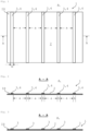
- Figure 1 now shows a top view of a surface of a metallic sheet 2 as the inner surface IS of the shielding structure 1.
- Strips 3 arranged parallel to one another at a distance a from one another are fixed on the sheet 2.
- these strips 3 consist of a bimetal, i.e. two layers of different layers with one another materially or positively connected metals.
- What is characteristic of a bimetal strip is a change in its shape when the temperature changes, which manifests itself as bending that progresses as the temperature increases due to different thermal expansion coefficients of the metals used.
- the deformation of a bimetal is reversible, so that this process of targeted deformation of the strips etc. is also reversible and can be repeated almost as desired through appropriate temperature changes.
- Figure 2 represents a sectional view in a plane AA of Figure 1 at a low temperature ⁇ n .
- the elements that deform upon reaching at least a predetermined temperature ⁇ h are arranged as strips 3 of a width b at a distance a from one another, essentially parallel to each other.
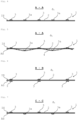
- Figure 3 shows the sectional view of Figure 2 at an increased temperature ⁇ h , through which the strips 3 deform or begin to deform.
- the deformation consists in the fact that the strips 3 curve perpendicular to a longitudinal axis and thus form ribs connected to the sheet 2 for mechanical stiffening of the sheet 2 connected to the strips 3.
- Figure 4 shows an alternative to the structure according to Figures 2 and 3 .
- Strips 3, 3a are provided here, the curvature of which is directed in opposite directions to one another in an alternating arrangement at an elevated temperature ⁇ h . This results in a sequence of differently shaped ribs in the selected cutting plane to stiffen the sheet 3.
- Figure 5 shows an embodiment in which the strips 3, 3a of Figure 4 are now fixed to the sheet 2 in such a way that the flat and therefore comparatively sound-soft sheet 2 is at the increased temperature ⁇ h under the influence of the strips 3, 3a itself assumes a wave-like cross section, while in the arrangement of Figure 4 only the elements or strips 3, 3a have been thermally induced deformed.
- a wave-like cross section is significantly stiffened mechanically and acoustically compared to a flat sheet 2. In this way, among other things, a natural frequency of the sheet metal 2 is changed in order to shift a possible resonance with an amplification of disturbing noises into more favorable frequency ranges, in particular outside of strong perception by the human ear.
- Figure 6 presents an alternative embodiment to the structure of the Figures 1 and 2
- strips 3 are now fixed on both surfaces IS, AS of the sheet 2.
- the strips 3 are fixed at common positions on the sheet 2, as the section in a plane BB shows. Curvatures of the strips in the same direction were chosen while establishing the increased temperature ⁇ h .
- a distance between the strips 3 has been more than doubled here and can be adapted to the requirements of a particular application. In particular, there is no need to provide a regular distance b between strips 3, which do not necessarily have to be arranged parallel to one another and/or have the same widths b in order to change the mechanical properties of the sheet 2.
- the sheet 2 itself can also be used as one of two layers of different metals connected to one another in a cohesive or form-fitting manner. Pairings of a sheet 2 made of steel with strips 4 made of zinc or a sheet 2 made of steel in combination with strips 4 made of the brass alloy are used, as already in Figure 2 indicated. Furthermore, the person skilled in the art knows, among other things, under the generic term "Invar" a group of alloys and compounds that have the remarkable property of having very small or sometimes even negative coefficients of thermal expansion in certain temperature ranges. Such materials are also used for strips 4 without any further graphic representations.
- the bare metals of the sheet 2 and each strip 4, which are free of oxide layers, are rolled together under pressure.
- cold welding and subsequent diffusion annealing treatment create an inseparable connection between a strip 4 and the metal of the sheet 2.
- Co-extrusion or extrusion are also used as manufacturing processes for bimetallic structures.
- congruent through holes are made at the ends of a strip 4 and the sheet 2 provided, through which the strip 4 is riveted and / or screwed to the sheet 2.
- the bimetal partners can also be fixed by gluing at the ends without drilling holes etc.
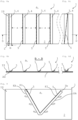
- FIGS. 8a, 8b show an alternative exemplary embodiment as a modification of the exemplary embodiments Figure 3 and 4 analogous in a top view Figure 1 and as a sectional view at elevated temperature ⁇ h .
- a linear fixation 5 of the strips 3 on the sheet 2 is now provided here. Through this fixation 5, only one edge of the relevant strip 3 is connected to the sheet 2, with the result that the strips 3 are at elevated temperature ⁇ h . Beyond the fixation 5, lift it off the sheet metal 2 by deforming the strips 3, approximately in the form of curved strips. In this position, the strips 3 form, on the one hand, an additional enlargement of the surface of the shielding structure 1, which act as cooling fins on the sheet 2. In addition, a surface of the shielding structure 1 is no longer flat, so that In addition to a mechanical stiffening of the sheet 2, there is also a significantly changed acoustic property and improved heat emission.
- Figure 8c converts that from Figure 8a in that here the linear fixation 5 of the strip 3 or section 3b on the sheet 2 no longer runs along an edge.
- the linear fixation 5 runs diagonally over the length of the strip 3 or section 3b.
- Figure 8d shows compared to Figure 8b A possible effect of this change is that the strip 3 or section 3b appears to twist under the influence of the increased temperature ⁇ h . This effect can be used acoustically to dampen and mechanically to stiffen the sheet 2.
- Figure 9 presents another alternative embodiment as a modification of Figure 8a
- an element no longer forms a strip 3, but a section 3b with a different geometry, indicated here as an example as a V-section. Due to a linear fixation 5 of the section 3b on the inner edges KI on the sheet 2, the outer edges KA can now lift off the sheet 2 under the influence of the increased temperature ⁇ h , while the inner edges KI must remain on the sheet 2.
- Figure 10a represents a top view analogously Figure 1 represent
- Figure 10b shows a representation of a section plane EE of the Figure 10a at an elevated temperature ⁇ h .
- a strip 3, 3a is now divided into sections 3c of a length L via a linear fixation 5 of the elements in the form of strips 3 on the sheet metal 2.
- a change is provided with regard to an edge to be fixed on the sheet 2 between adjacent sections 3c.
- the sections 3c bend in opposite directions from an increased temperature ⁇ h and stand out from the sheet 2 in alternating ways.
- Such a change is of course also in accordance with an order Figure 8a applicable.
- an element here in the form of sections 3c, has incisions, which in this exemplary embodiment are realized in the form of punchings.
- square punchings 6a and triangular punchings 6b are shown here in sections 3c of the bimetal strips. Possible shapes are not limited to these basic geometric shapes and their size can therefore be tailored to specific frequency ranges depending on the application, for example to influence an acoustic effect.
- the sections 3c in this exemplary embodiment lie flat and level on the sheet metal 2 at each longitudinal edge held by a linear fixation 5.
- a deformation of the bimetal used begins, which causes a curvature in a direction, as indicated by the dotted arrows in Figure 10a indicated.
- a special treatment or processing of the free punchings 6a, 6b in the area of a connecting edge 7 to the section 3c causes a 3D unfolding of each of the sections 3c on the sheet 2.
- a convectively accessible space above the sheet 2 is thus further enlarged, so that also heat dissipation is further improved.
- the different bends of the bimetal parts in the area of the punchings 6a, 6b reinforce a labyrinth structure of this arrangement and thus exert an increased influence on the acoustic properties of the entire shielding structure 1 during the transition to predetermined areas of increased temperature ⁇ h .
- this change in mechanical properties under the influence of temperature during operation in different driving modes can be used specifically to reversibly influence the structure of at least part of a shielding structure 1 and thus at the same time as an acoustically effective function.
- Different deformations can also be achieved from different temperatures ⁇ h1 , ⁇ h2 , ... through selection, dimensioning and shaping as well as other treatment of the bimetals.
Landscapes
- Engineering & Computer Science (AREA)
- General Engineering & Computer Science (AREA)
- Mechanical Engineering (AREA)
- Physics & Mathematics (AREA)
- Acoustics & Sound (AREA)
- Chemical & Material Sciences (AREA)
- Combustion & Propulsion (AREA)
- Soundproofing, Sound Blocking, And Sound Damping (AREA)
- Laminated Bodies (AREA)
Description
Die vorliegende Erfindung betrifft eine Abschirmstruktur zum Abschirmen eines Gegenstandes gegen Hitze und/oder Schall, wobei die Abschirmstruktur eine dem Gegenstand zugewandte Innenoberfläche und eine dem Gegenstand abgewandte Außenoberfläche aufweist.The present invention relates to a shielding structure for shielding an object against heat and/or sound, the shielding structure having an inner surface facing the object and an outer surface facing away from the object.
Aus dem Stand der Technik sind diverse Bauformen von Abschirmstrukturen bekannt, z.B. als Hitzeschilde. Ebenfalls sind Abschirmstrukturen bekannt, die neben einer Temperaturdämmung auch eine akustische Dämmung aufweisen. Eine akustische Wirksamkeit von Abschirmstrukturen kann durch Einbringen von Isoliermaterial realisiert und in Kombination mit offenporigen schallzugewandten Blechlagen noch verstärkt werden. In anderen Frequenzbereichen ist hingegen eine höhere Steifigkeit einer Abschirmstruktur erwünscht, um eine Schallabstrahlung zu mindern. Eine größere mechanische Steifigkeit wird durch Einbringen von Strukturierungen, wie z.B. Sicken, in akustisch relevanten Bereichen erreicht. Damit zielen beide vorstehend beschriebenen Maßnahmen jeweils auf einen bestimmten Frequenzbereich ab, bei dem sie wirken.Various designs of shielding structures are known from the prior art, for example as heat shields. Shielding structures are also known which, in addition to thermal insulation, also have acoustic insulation. The acoustic effectiveness of shielding structures can be achieved by introducing insulating material and can be further enhanced in combination with open-pored sheet metal layers facing sound. In other frequency ranges, however, a higher rigidity of a shielding structure is desired in order to reduce sound radiation. Greater mechanical rigidity is achieved by introducing structures, such as beads, in acoustically relevant areas. Both measures described above are therefore aimed at a specific frequency range at which they work.
Nachteilig ist bei bekannten Lösungen, dass entweder mechanische Verbesserungen durch Einbringen von Strukturmaßnahmen auf Kosten einer guten akustischen Effizienz erzielt werden können - was Effekte eher in höheren Frequenzbereichen betrifft, oder gute akustische Wirksamkeiten aufgrund einer biegeweichen Struktur auf Kosten einer mechanischen Festigkeit erreicht werden - mit Wirkung eher in niedrigen Frequenzbereichen. Durch diesen Zielkonflikt können nicht beide Ziele zugleich in zufriedenstellendem Maß erreicht werden.The disadvantage of known solutions is that either mechanical improvements can be achieved by introducing structural measures at the expense of good acoustic efficiency - which affects effects more in higher frequency ranges, or good acoustic effectiveness can be achieved due to a flexible structure at the expense of mechanical strength - with effect rather in low frequency ranges. Due to this conflict of goals, both goals cannot be achieved satisfactorily at the same time.
Die vorliegende Erfindung hat die Aufgabe eine Abschirmstruktur zum Abschirmen eines Gegenstandes gegen Hitze und/oder Schall mit verbesserten mechanischen Eigenschaften bereit zu stellen, durch die der oben beschriebene klassische Zielkonflikt zumindest gemildert wird.The present invention has the object of providing a shielding structure for shielding an object against heat and/or sound with improved mechanical properties, through which the classic conflict of objectives described above is at least mitigated.
Diese Aufgabe wird erfindungsgemäß durch die Merkmale von Anspruch 1 gelöst. Demnach weist die Abschirmstruktur ein Blech mit einer dem Gegenstand zugewandten Innenoberfläche und eine dem Gegenstand abgewandten Außenseite auf und ist dadurch gekennzeichnet, dass eine Innenoberfläche der Abschirmstruktur mit Elementen bestückt ist, die dazu ausgebildet sind, sich oder auch das Blech mit Erreichung mindestens einer vorbestimmten Temperatur zu verformen. Erfindungsgemäß wird dadurch ein Aufbau mit einer Art von thermisch induziertem Umschalten von einer weichen und damit akustisch mehr bedämpfend funktionierender zu einer biegesteifen und durch mechanische Eigenschaften dominierten Struktur erzielt.This object is achieved according to the invention by the features of
Vorteilhafte Weiterbildungen sind Gegenstand der Unteransprüche. Demnach ist die Verformung der Elemente und/oder die Verformung der Oberfläche der Abschirmstruktur durch die Elemente als Verrippung ausgebildet. Im erstgenannten Fall bilden die Elemente selber eine Verrippung, im zweitgenannten Fall wird durch die Elemente eine Verrippung der Oberfläche der Abschirmstruktur gebildet, insbesondere die einer inneren Oberfläche bzw. Innenoberfläche. Eine Verrippung kann je nach konstruktiver Ausformung linienförmig verlaufen oder sich auf einen z.B. eher ovalen Bereich der Oberfläche der Abschirmstruktur beschränken, um dort gezielt eine Ausbildung von Schwingungsmoden zu unterdrücken.Advantageous further training is the subject of the subclaims. Accordingly, the deformation of the elements and/or the deformation of the surface of the shielding structure is formed by the elements as ribbing. In the first-mentioned case, the elements themselves form a ribbing, in the second-mentioned case, the elements form a ribbing of the surface of the shielding structure, in particular that of an inner surface or inner surface. Depending on the design, ribbing can be linear or limited to, for example, a more oval area of the surface of the shielding structure in order to specifically suppress the formation of vibration modes there.
In einer bevorzugten Ausführungsform der Erfindung ist eine Verformung der Elemente reversibel. Damit kann mit Erreichung einer Temperatur bzw. eines Temperaturbereichs ein Umschalten zwischen einer relativ weichen und einer eher mechanisch biegesteifen Struktur und wieder zurück erfolgen.In a preferred embodiment of the invention, deformation of the elements is reversible. This means that when a temperature or a temperature range is reached, a switch can take place between a relatively soft and a more mechanically rigid structure and back again.
Die Elemente umfassen gemäß einer Ausführungsform der Erfindung Bimetall-Abschnitte, oder die Elemente bilden selber Abschnitte aus Bimetall. Vorzugsweise bestehen die Elemente aus Bimetall-Abschnitten in der Form von Streifen oder länglichen Abschnitten von Streifen. Alternativ oder zusätzlich bilden die Elemente zusammen mit dem Metall des Blechs, an und/oder mit dem sie insbesondere in Form von Streifen fixiert sind, selber ein Bimetall. Von Bimetallen ist bekannt, dass sie sich mit Erreichung mindestens einer vorbestimmten Temperatur fortschreitend und i.d.R. vollständig reversibel verformen können. Je nach Materialauswahl und Dimensionierung sind unterschiedliche Temperaturen für das Einsetzen einer vorbestimmten Verformung einstellbar.According to one embodiment of the invention, the elements comprise bimetal sections, or the elements themselves form sections made of bimetal. Preferably the elements consist of bimetallic sections in the form of strips or elongated sections of strips. Alternatively or additionally, the elements together with the metal of the sheet to and/or with which they are fixed, in particular in the form of strips, form itself a bimetal. It is known that bimetals can deform progressively and usually completely reversibly when at least a predetermined temperature is reached. Depending on the material selection and dimensioning, different temperatures can be set for the onset of a predetermined deformation.
In einer bevorzugten Ausführungsform der Erfindung sind die Elemente zueinander jeweils in einem Abstand im Wesentlichen parallel verlaufend ausgerichtet angeordnet und an oder auf dem Blech fixiert, das die Innenoberfläche der Abschirmstruktur bildet. Die Fixierung erfolgt vorzugsweise an mindestens einer der Längskanten, sie kann aber auch z.B. diagonal über eine Länge eines Streifens oder Abschnitts verlaufen.In a preferred embodiment of the invention, the elements are each arranged at a distance from one another, aligned essentially parallel, and fixed to or on the sheet metal that forms the inner surface of the shielding structure. The fixation preferably takes place on at least one of the longitudinal edges, but it can also, for example, run diagonally over a length of a strip or section.
Vorteilhafterweise weisen zueinander benachbart angeordnete Elemente eine jeweils entgegengesetzt gerichtete thermisch induzierte Verformung und insbesondere eine Krümmung auf. Damit folgen ab einem vorbestimmten Temperaturbereich benachbart relative Maxima und relative Minima bzw. Berge und Täler zur Steigerung einer mechanischen Aufsteifung einer Flächenstruktur aufeinander.Elements arranged adjacent to one another advantageously have an oppositely directed thermally induced deformation and in particular a curvature. This means that from a predetermined temperature range, relative maxima and relative minima or mountains and valleys follow one another in order to increase the mechanical stiffening of a surface structure.
In einer besonders bevorzugten Ausführungsform der Erfindung sind alle Elemente in einem gleichen Temperaturbereich einer erhöhten Temperatur aktivierbar. Alternativ sind auch aufeinander definiert folgende Temperaturbereiche ausgeführt, um z.B. eine fortschreitende Auffaltung und weiter fortschreitende mechanische Aufsteifungen der Innenoberfläche der Abschirmstruktur zu realisieren.In a particularly preferred embodiment of the invention, all elements can be activated in a same temperature range of an elevated temperature. Alternatively, successive temperature ranges are also implemented in a defined manner, for example to realize a progressive unfolding and further progressive mechanical stiffening of the inner surface of the shielding structure.
Vorzugsweise sind die Elemente durch Kaltverschweißung, Vernietung, Verklebung und/oder Verschraubung an dem Blech fixiert. Für den Fachmann ist erkennbar, dass sich Alternativen und mögliche Mischformen von thermisch induzierten Verformungen als Folge einer jeweiligen Fixierung der Elemente auf und/oder an der Oberfläche des Blechs der Abschirmstruktur ergeben. In einem Fall verformt sich nur ein betreffendes Element, in einem anderen Fall wird ein Bereich des Blechs durch das Element mit verformt, wie nachfolgend noch anhand eines Ausführungsbeispiels dargestellt wird.The elements are preferably fixed to the sheet metal by cold welding, riveting, gluing and/or screwing. It is clear to the expert that there are alternatives and possible mixed forms of thermally induced deformations result from a respective fixation of the elements on and/or on the surface of the sheet of the shielding structure. In one case, only one element in question is deformed, in another case, an area of the sheet metal is also deformed by the element, as will be shown below using an exemplary embodiment.
In einer bevorzugten Ausführungsform der Erfindung ist eine mindestens abschnittsweise linienförmige Fixierung eines Elements oder Streifens an dem Blech vorgesehen. Durch diese Fixierung ist eine Kante des Streifens oder Abschnitts mit dem Blech verbunden. Diese Fixierung ist vorzugsweise punktförmig und/oder in Form kurzer Abschnitte ausgeführt. Alternativ ist eine derartige Fixierung an und auf dem Blech entlang einer Diagonale über den Streifen oder Abschnitt möglich, wie noch anhand der Zeichnung dargestellt.In a preferred embodiment of the invention, an element or strip is fixed to the sheet metal in a linear manner at least in sections. This fixation connects one edge of the strip or section to the sheet metal. This fixation is preferably carried out in a punctiform manner and/or in the form of short sections. Alternatively, such a fixation on and on the sheet metal along a diagonal across the strip or section is possible, as shown in the drawing.
Alternativ oder zusätzlich werden in einer Ausführungsform der Erfindung auch entsprechende Elemente an einer gegenüberliegenden Oberfläche der Abschirmstruktur vorgesehen. Damit werden dann eine innere und eine äußere Oberfläche eines dem Gegenstand zugewandten Blechs der Abschirmstruktur bestückt.Alternatively or additionally, in one embodiment of the invention, corresponding elements are also provided on an opposite surface of the shielding structure. An inner and an outer surface of a sheet of the shielding structure facing the object are then equipped with this.
Vorteilhafterweise sind Streifen an gemeinsamen Positionen an dem Blech fixiert. Diese Anordnung bewirkt eine besonders starke mechanische Versteifung.Strips are advantageously fixed at common positions on the sheet. This arrangement causes a particularly strong mechanical stiffening.
Gemäß einer wesentlichen Weiterbildung der Erfindung weist ein Element Einschnitte auf. Diese Einschnitte werden vorzugsweise in Form von Freistanzungen ausgeführt, alternativ als Ätzungen oder als Ergebnis von Laser- oder Wasserstrahl-Schneidprozessen.According to a significant development of the invention, an element has incisions. These incisions are preferably made in the form of free punchings, alternatively as etchings or as a result of laser or water jet cutting processes.
In einer bevorzugten Ausführungsform der Erfindung ist eine Freistanzung mindestens im Bereich einer Verbindungskante zu dem Element, das beispielsweise in Form eines Streifen und/oder dem Abschnitt ausgebildet ist, hin durch eine Behandlung oder Bearbeitung dazu ausgebildet, bei einem Übergang in vorbestimmte Bereiche erhöhter Temperatur ϑh eine dreidimensionale bzw. 3D-Auffaltung gegenüber dem Blech und/oder dem Streifen oder dem Abschnitt zu bewirken. Eine mechanische Versteifung ist gemäß dieser Ausführungsform vorteilhafterweise so mit einer noch weiteren Vergrößerung einer freien Oberfläche verbunden. Diese Vergrößerung der Oberfläche wirkt zudem nach Art eines Labyrinths. Damit treten zu einer geänderten mechanischen Eigenschaft eine verbesserte Wärmeabfuhr mit erhöhter akustischer Dämpfung hinzu, die über eine Dimensionierung der Einschnitte und/oder Form der mindestens einen Freistanzung o.ä. einstellbar sind, insbesondere in Abstimmung auf bestimmte Frequenzen.In a preferred embodiment of the invention, a free punching is formed at least in the area of a connecting edge to the element, which is designed, for example, in the form of a strip and / or the section, through treatment or processing, during a transition to predetermined areas of increased temperature ϑ h to effect a three-dimensional or 3D unfolding relative to the sheet and/or the strip or the section. According to this embodiment, a mechanical stiffening is advantageously associated with an even further enlargement of a free surface. This enlargement of the surface also acts like a labyrinth. In addition to a changed mechanical property, improved heat dissipation with increased acoustic damping is achieved, which can be adjusted by dimensioning the cuts and/or shape of the at least one free punching or the like, in particular in coordination with certain frequencies.
Dem Fachmann ist verständlich, dass je nach Anwendungsfall und Betrachtungsweise die vorstehend gewählten Begriffe "Innenoberfläche" und "Außenseite" gegeneinander mit Blick auf ein technisch zu erreichendes Ziel austauschbar sind. So kann eine akustische Bedämpfung nach Innen gerichtet sein, aber auch nach außen eine akustische Abstrahlung gemindert werden. Eine vergrößerte Oberfläche kann nach Innen gerichtet eine Entwärmung eines benachbarten Gegenstands fördern, nach außen hin gerichtet eine Wärmeabgabe durch freie oder erzwungene Konvektion verbessern. In diesem Sinne kann eine Innenoberfläche zu einer Außenseite werden und umgekehrt, abhängig von einem Ort eines erwünschten technischen Effekts gemäß der vorliegenden Erfindung.The person skilled in the art will understand that, depending on the application and perspective, the terms “inside surface” and “outside” chosen above can be interchanged with one another with a view to achieving a technically achieved goal. In this way, acoustic damping can be directed inwards, but acoustic radiation can also be reduced to the outside. An enlarged surface can promote heat dissipation from a neighboring object directed inwards, and improve heat release through free or forced convection towards the outside. In this sense, an inside surface can become an outside surface and vice versa depending on a location of a desired technical effect according to the present invention.
Nachfolgend werden weitere Merkmale und Vorteile erfindungsgemäßer Ausführungsformen unter Bezugnahme auf Ausführungsbeispiele anhand der Zeichnung näher erläutert. Darin zeigen in schematischer Darstellung:
- Figur 1:
- eine Draufsicht auf eine Außenseite einer Abschirmstruktur;
- Figur 2:
- eine Schnittdarstellung in einer Ebene A-A von
Figur 1 - Figur 3:
- die Schnittdarstellung von
Figur 2 - Figur 4:
- eine Alternative zu dem Aufbau gemäß
Figur 3 - Figur 5:
- ein weiteres Ausführungsbeispiel als Alternative zu dem Aufbau der
Figur 2 bei erhöhter Temperatur; - Figur 6:
- ein Ausführungsbeispiel als Alternative zu dem Aufbau der
Figuren 1 und 2 bei erhöhter Temperatur; - Figur 7:
- ein alternatives Ausführungsbeispiel als Abwandlung von
Figur 6 bei erhöhter Temperatur; - Figuren 8a bis 8d:
- alternative Ausführungsbeispiele als Abwandlungen der Ausführungsbeispiele der
Figuren 3 und4 in einerDraufsicht analog Figur 1 und als Schnittdarstellung bei erhöhter Temperatur; - Figur 9:
- ein alternatives Ausführungsbeispiel als Abwandlung von
Figur 8a und - Figuren 10a, 10b:
- ein weiteres alternatives Ausführungsbeispiel als Abwandlung der Ausführungsbeispiele der
Figur 8a in einerDraufsicht analog Figur 1 und als Darstellung einer Schnittebene E-E bei erhöhter Temperatur.
- Figure 1:
- a top view of an outside of a shielding structure;
- Figure 2:
- a sectional view in a plane AA of
Figure 1 ; - Figure 3:
- the sectional view of
Figure 2 at elevated temperature; - Figure 4:
- an alternative to the structure according to
Figure 3 at elevated temperature; - Figure 5:
- another embodiment as an alternative to the structure of
Figure 2 at elevated temperature; - Figure 6:
- an embodiment as an alternative to the structure of
Figures 1 and 2 at elevated temperature; - Figure 7:
- an alternative embodiment as a modification of
Figure 6 at elevated temperature; - Figures 8a to 8d:
- alternative embodiments as modifications of the embodiments of
Figures 3 and4 analogous in a top viewFigure 1 and as a sectional view at elevated temperature; - Figure 9:
- an alternative embodiment as a modification of
Figure 8a and - Figures 10a, 10b:
- a further alternative exemplary embodiment as a modification of the exemplary embodiments
Figure 8a analogous in a top viewFigure 1 and as a representation of a section plane EE at elevated temperature.
Über die verschiedenen Abbildungen und Ausführungsbeispiele hinweg werden für gleiche Elemente stets die gleichen Bezugszeichen verwendet.Across the various illustrations and exemplary embodiments, the same reference numbers are always used for the same elements.
Die nun beschriebenen erfindungsgemäßen Ausführungsformen zeigen alle eine Abschirmstruktur 1 zum Abschirmen eines nicht weiter dargestellten Gegenstandes gegen Hitze und/oder Schall in einem Kraftfahrzeug. Eine solche Abschirmstruktur 1 kann beliebige auch dreidimensionale Formen aufweisen und wird hier ohne Beschränkung und nur der Einfachheit halber als rechteckiges Element dargestellt. Dieses rechteckige Element stellt im Fall einer mehrschichtig aufgebauten Abschirmstruktur ein dem abzuschirmenden Gegenstand zugewandtes Blech 2 dar.The embodiments according to the invention now described all show a shielding
Ein regulärer Fahrbetrieb in einem unteren Fahrzeuggeschwindigkeitsbereich des Kraftfahrzeugs mit Antrieb durch eine oder Betrieb einer Verbrennungskraftmaschine geht meist mit niedrigeren Verbrennungstemperaturen und daher kleinen thermischen Lasten der Bauteile einher. In diesen Frequenzbereichen ist es aber besonders wichtig, eine gut wirkende akustische Maßnahme durch die Abschirmstruktur 1 bereitzustellen, da der Anteil der Schallabstrahlung verbrennungsmotorischer Geräusche eine hohe Gewichtung gegenüber einem z.B. durch Abrollgeräusche der Reifen, Windgeräusche etc. hervorgerufenen Gesamtgeräuschniveau in einem solchen Fahrbetrieb hat. Alternative Antriebskonzepte zeigen ein vergleichbares Verhalten. Für eine wirksame Schalldämmung sind somit biegeweiche Strukturen der Abschirmstruktur 1 mit hoher flächenbezogener Masse zu bevorzugen. Eine akustische Wirksamkeit von Abschirmteilen kann durch Einbringen von Isoliermaterial in Kombination mit offenporigen und/oder mechanisch weichen schallzugewandten Blechlagen realisiert werden.Regular driving in a lower vehicle speed range of the motor vehicle with drive by or operation of an internal combustion engine is usually accompanied by lower combustion temperatures and therefore small thermal loads on the components. In these frequency ranges, however, it is particularly important to provide a well-acting acoustic measure through the shielding
Ändert sich jedoch der Fahrbetrieb hin zu einem höher beaufschlagten Lastfall in einem höheren Geschwindigkeits- und damit auch höheren Verbrennungsmotorlastbereich sind gute Eigenschaften hinsichtlich Steifigkeit und Strukturdynamik bei der Abschirmstruktur 1 wünschenswert und auch hinsichtlich einer Betriebsfestigkeit zu bevorzugen. Eine größere mechanische Steifigkeit wird z.B. durch Einbringen von Strukturierungen z.B. in Form von Sicken in relevanten Bereichen erreicht.However, if the driving operation changes to a higher load case in a higher speed and thus also higher internal combustion engine load range, good properties in terms of rigidity and structural dynamics are desirable for the shielding
Beide vorstehend beschriebenen Maßnahmen zielen damit jeweils auf einen bestimmten Frequenzbereich in einem jeweiligen Anwendungs-Szenario ab. Erfindungsgemäß wird nun eine Lösung zur Vereinbarung dieser Maßnahmen in Form einer Kombination von akustischen mit mechanischen Eigenschaften mit einem Wechsel dieser Eigenschaften geschaffen, der einem jeweiligen Anwendungs-Szenario entsprechend ausgebildet ist und durch eine jeweilige Temperatureinwirkung gesteuert wird. Dieser Wechsel der mechanischen Eigenschaften unter Temperatureinwirkung kann somit während des Betriebs in unterschiedlichen Fahr-Modi gezielt zur Beeinflussung der Abschirmstruktur 1 und somit zugleich auch als akustisch wirksame Funktion genutzt werden, die auch eine mechanische Anregung der Abschirmstruktur 1 mit störender Abstrahlung von Schall als zusätzlichem Geräusch mindert.Both measures described above are each aimed at a specific frequency range in a respective application scenario. According to the invention, a solution is now created for combining these measures in the form of a combination of acoustic and mechanical properties with a change of these properties, which is designed according to a respective application scenario and is controlled by a respective temperature effect. This change in mechanical properties under the influence of temperature can thus be used specifically to influence the shielding
Die Abschirmstruktur 1 weist dazu eine dem nicht weiter dargestellten Gegenstand zugewandten Innenoberfläche IS und eine dem Gegenstand abgewandten Außenseite AS auf.
Im Unterschied zu dem Ausführungsbeispiel von
Statt der Verwendung von Streifen 3, 3a aus mindestens einer Bimetall-Kombination kann das Blech 2 auch selber als eine von zwei Schichten unterschiedlicher, miteinander stoffschlüssig oder formschlüssig verbundener Metalle verwendet werden. Dabei werden Paarungen von einem Blech 2 aus Stahl mit Streifen 4 aus Zink oder auch einem Blech 2 aus Stahl in Kombination mit Streifen 4 aus der Legierung Messing verwendet, wie schon in
In einem Herstellungsverfahren werden die blanken und von Oxidschichten freien Metalle des Blechs 2 und jeweils eines Streifens 4 unter Druck aufeinander gewalzt. In der Kontaktzone entsteht durch Kaltverschweißung und eine anschließende Diffusionsglühbehandlung eine unlösbare Verbindung zwischen einem Streifen 4 und dem Metall des Blechs 2. Auch Co-Extrusion oder Strangpressen werden als Herstellungsverfahren für Bimetall-Strukturen genutzt. Bei einer anderen Ausführungsform werden zur Herstellung eines Bimetalls an Enden eines Streifen 4 und dem Blech 2 deckungsgleiche Durchgangsbohrungen vorgesehen, durch die der Streifen 4 mit dem Blech 2 vernietet und/oder verschraubt wird. Ohne Bohrungen etc. ist in niedrigeren Temperaturbereichen auch eine Fixierung der Bimetall-Partner durch eine endseitige Verklebung möglich.In a manufacturing process, the bare metals of the
Damit können prinzipiell alle vorstehend unter der Verwendung von Streifen 3, 3a aus Bimetall beschriebenen Anordnungen analog nachgebildet werden, insbesondere die von
Nicht weiter zeichnerisch dargestellt sind Variationen z.B. von
Die Abbildungen der
In der in
Das Ausführungsbeispiel von
Die Abbildungen der
Darüber hinaus weist ein Element, hier in Form der Abschnitte 3c, Einschnitte auf, die in diesem Ausführungsbeispiel in Form von Freistanzungen realisiert sind. Beispielhaft werden hier viereckige Freistanzungen 6a sowie dreieckige Freistanzungen 6b in den Abschnitten 3c der Bimetall-Streifen dargestellt. Mögliche Formgebungen sind nicht auf diese geometrischen Basisformen geschränkt und können so auch in ihrer Größe je nach Anwendungsfall z.B. zur Beeinflussung einer akustischen Wirkung auf bestimmte Frequenzbereiche abgestimmt werden. Bei niedrigeren Temperaturen ϑn liegen die Abschnitte 3c in diesem Ausführungsbeispiel an jeweils einer Längskante durch eine linienförmige Fixierung 5 gehalten flach und eben auf dem Blech 2 auf.In addition, an element, here in the form of
In einfacher Weise ebenfalls realisierbar, hier aber nicht weiter dargestellt, ist es möglich, die Abschnitte 3c bei niedrigeren Temperaturen ϑn von dem Blech 2 abstehen zu lassen, um die Abschnitte 3c sich ab einer erhöhten Temperatur ϑh in sonstiger Weise zur Erzielung thermischer und/oder akustischer Effekte zu krümmen. Dabei könnten sich die Abschnitte 3c an das Blech 2 anlegen.Also feasible in a simple manner, but not shown here, it is possible to let the
Mit Erreichen einer vorbestimmten erhöhten Temperatur ϑh setzt in diesem Ausführungsbeispiel eine Verformung des verwendeten Bimetalls ein, das eine Krümmung in einer Richtung verursacht, wie durch die gepunkteten Pfeile in
In jedem Fall und über alle Ausführungsbeispiele hinweg kann dieser Wechsel mechanischer Eigenschaften unter Temperatureinwirkung während des Betriebs in unterschiedlichen Fahr-Modi gezielt zur reversiblen Beeinflussung der Struktur mindestens eines Teils einer Abschirmstruktur 1 und somit zugleich als akustisch wirksame Funktion genutzt werden. Dabei sind unterschiedliche Verformungen auch ab verschiedenen Temperaturen ϑh1, ϑh2, ... durch Auswahl, Dimensionierung und Formung sowie sonstige Behandlung der Bimetalle realisierbar.In any case and across all exemplary embodiments, this change in mechanical properties under the influence of temperature during operation in different driving modes can be used specifically to reversibly influence the structure of at least part of a shielding
- 11
- AbschirmstrukturShielding structure
- 22
- Blechsheet
- 33
-
Streifen aus Bimetall
3a Streifen aus Bimetall mit entgegengesetzter Krümmung
3b Abschnitt aus Bimetall mit von Streifen abweichender Flächen-Form
3c Abschnitt eines Streifens mit einer Länge LBimetal strips
3a Bimetal strips with opposite curvature
3b Section made of bimetal with a surface shape that deviates from stripes
3c Section of a strip with a length L - 44
-
Streifen aus nur einem Metall zur Bildung einer Bimetall-Anordnung zusammen mit dem Blech 2Strips made of just one metal to form a bimetal arrangement together with
sheet metal 2 - 55
-
linienförmige Fixierung des Streifens 3 oder Abschnitts 3b an dem Blech 2Line-shaped fixation of the
strip 3 orsection 3b on thesheet 2 - 6a6a
-
viereckige Freistanzung in dem Streifen 3b aus Bimetallsquare punching in the
strip 3b made of bimetal - 6b6b
-
dreieckige Freistanzung in dem Streifen 3b aus BimetallTriangular punching in the
strip 3b made of bimetal - 77
-
Verbindungskante einer Freistanzung zu dem Abschnitt 3bConnecting edge of a free punching to
section 3b
- aa
-
Abstand der Streifen 3, 3a, 4Distance between
strips - bb
-
Breite der Streifen 3, 3a, 4Width of
strips - ASAS
-
Außenseite des Blechs 2Outside of the
sheet 2 - ISIS
-
Innenoberfläche des Blechs 2Inner surface of the
sheet 2 - KIAI
- InnenkanteInside edge
- KAKA
- AußenkanteOuter edge
- LL
-
Länge des Abschnitts 3bLength of
section 3b - ϑnϑn
- niedrige Temperaturlow temperature
- ϑhϑh
- eine vorbestimmte erhöhte Temperatur einer einsetzenden Verformung eines Bimetallsa predetermined elevated temperature of onset deformation of a bimetal
Claims (15)
- Shielding structure (1) for shielding an object against heat and/or sound, wherein the shielding structure (1) comprises a metal sheet (2) with an inner surface (IS) facing the object and an outer surface (AS) facing away from the object,
characterized in that
the inner surface (IS) of the sheet metal (2) of the shielding structure (1) is equipped with elements which are designed to deform themselves or also the sheet metal (2) from a soft and thus acoustically more damping structure to a rigid structure when at least one predetermined temperature (ϑh) is reached. - Shielding structure (1) according to the preceding claim, characterized in that a deformation of the elements and/or of the sheet metal (2) by the elements is designed as ribbing.
- Shielding structure (1) according to one of the preceding claims, characterized in that a deformation of the elements is reversible.
- Shielding structure (1) according to one of the preceding claims, characterized in that the elements comprise bimetal sections or are formed as sections of bi-metal.
- Shielding structure (1) according to the preceding claim, characterized in that the elements consist of bi-metal sections in the form of strips (3, 3a) and/or elongated sections (3b, 3c).
- Shielding structure (1) according to one of the preceding claims, characterized in that the elements form a bimetal together with the metal of the sheet (2) to which and/or with which they are fixed.
- Shielding structure (1) according to one of the preceding claims, characterized in that the elements are arranged at a distance (a) from one another, running essentially parallel, and are fixed to or on the sheet metal (2), preferably on at least one of the longitudinal edges or else running diagonally over a length of a strip or section.
- Shielding structure (1) according to one of the preceding claims, characterized in that elements arranged adjacent to one another exhibit a thermally induced deformation directed in opposite directions, in particular a thermally induced curvature.
- Shielding structure (1) according to one of the preceding claims, characterized in that all elements can be activated in the same temperature range of an elevated temperature (ϑh).
- Shielding structure (1) according to one of the preceding claims, characterized in that the elements are fixed to the sheet metal (2) by cold welding, riveting, bonding and/or screwing.
- Shielding structure (1) according to one of the preceding claims, characterized in that an at least sectional linear fixation (5) of a strip (3) to the sheet metal (2) is provided, by means of which preferably an edge (5) of the strip (3) is fixed to the sheet metal (2).
- Shielding structure (1) according to one of the preceding claims, characterized in that elements in the form of strips (3, 3a) and/or sections (3b, 3c) are fixed on both surfaces (IS, AS) of the sheet (2).
- Shielding structure (1) according to the preceding claim, characterized in that strips (3, 3a) and/or sections (3b, 3c) are fixed to the sheet (2) at common positions.
- Shielding structure (1) according to one of the preceding claims, characterized in that an element has incisions, preferably in the form of free die-cuttings or punchings (6a, 6b).
- Shielding structure (1) according to the preceding claim, characterized in that a free die-cutting or punching (6a, 6b) at least in the region of a connecting edge (7) to the element in the form of a strip (3, 3a) and/or cutoffs (3b, 3c) is designed by a treatment or processing to cause 3D folding relative to the sheet (2) and/or the strip (3, 3a) and/or the section (3b, 3c) at a transition to predetermined regions of increased temperature (ϑh).
Applications Claiming Priority (2)
| Application Number | Priority Date | Filing Date | Title |
|---|---|---|---|
| DE102019111404.7A DE102019111404A1 (en) | 2019-05-02 | 2019-05-02 | Shielding structure |
| PCT/EP2020/062352 WO2020221941A1 (en) | 2019-05-02 | 2020-05-04 | Shielding structure |
Publications (2)
| Publication Number | Publication Date |
|---|---|
| EP3963247A1 EP3963247A1 (en) | 2022-03-09 |
| EP3963247B1 true EP3963247B1 (en) | 2024-01-10 |
Family
ID=71401706
Family Applications (1)
| Application Number | Title | Priority Date | Filing Date |
|---|---|---|---|
| EP20735269.1A Active EP3963247B1 (en) | 2019-05-02 | 2020-05-04 | Shielding structure |
Country Status (3)
| Country | Link |
|---|---|
| EP (1) | EP3963247B1 (en) |
| DE (1) | DE102019111404A1 (en) |
| WO (1) | WO2020221941A1 (en) |
Family Cites Families (4)
| Publication number | Priority date | Publication date | Assignee | Title |
|---|---|---|---|---|
| DE502006002271D1 (en) * | 2006-09-27 | 2009-01-15 | Reinz Dichtungs Gmbh | heat shield |
| DE102007024553A1 (en) * | 2007-05-25 | 2008-11-27 | Elringklinger Ag | Structural component, in particular heat shield |
| DE102008003721B4 (en) * | 2008-01-09 | 2014-02-13 | Audi Ag | Heat shield for a motor vehicle |
| KR101817759B1 (en) * | 2016-08-26 | 2018-01-11 | (주)영진 | A two-layer board for a vehicle heat protector and a manufacturing method |
-
2019
- 2019-05-02 DE DE102019111404.7A patent/DE102019111404A1/en active Pending
-
2020
- 2020-05-04 EP EP20735269.1A patent/EP3963247B1/en active Active
- 2020-05-04 WO PCT/EP2020/062352 patent/WO2020221941A1/en unknown
Also Published As
| Publication number | Publication date |
|---|---|
| DE102019111404A1 (en) | 2020-11-05 |
| WO2020221941A1 (en) | 2020-11-05 |
| EP3963247A1 (en) | 2022-03-09 |
Similar Documents
| Publication | Publication Date | Title |
|---|---|---|
| DE102011077361A1 (en) | Spring for a shaft / hub connection with overload protection function, especially for tailgate drives | |
| EP2032393B1 (en) | Structured component, in particular heat shield | |
| EP1794531A1 (en) | Metal side-plate for a radiator | |
| WO2011032800A1 (en) | Ball roller bearing | |
| EP3963247B1 (en) | Shielding structure | |
| EP2832464B1 (en) | Lamella element and method for producing a lamella element | |
| EP1869390A1 (en) | Heat exchanger, in particular for a motor vehicle | |
| DE4020891A1 (en) | TUB-LIKE ROCKER LEVER | |
| EP0672520A1 (en) | Multilayered, cold formable and deep drawable metal composites | |
| DE112012002384T5 (en) | support element | |
| DE19645517A1 (en) | Door leaf, in particular for elevator doors | |
| DE102019132450A1 (en) | Battery housing for a vehicle driven by an electric motor | |
| WO2008151680A1 (en) | Heat exchanger | |
| EP1702803B1 (en) | Shielding element | |
| EP2901099B1 (en) | Deformation element and method for producing a deformation element | |
| WO2006111197A1 (en) | Double-stranded waste gas system | |
| DE102005008667A1 (en) | Heat shield for motor vehicle`s diesel engine components, has shielding part fixable at vehicle or machine parts by fixing units, and provided with compensation part that compensates temperature conditioned different material expansions | |
| DE1601859B2 (en) | Hermetically sealed cold machine | |
| DE19929872A1 (en) | Shaft strip for vehicle door and window seal is made from single sheet metal strip bent round and welded to form integral hollow steel section and off-set steel vane to hold window seal | |
| EP1495924B1 (en) | Vehicle body part, in particular a bonnet | |
| DE102010060157A1 (en) | Deformation element for bumper system of motor vehicle, has elongated hollow body that is made of metal sheet, where metal sheet has multiple longitudinal beads | |
| DE102019119748A1 (en) | Insulation element | |
| DE102008062222A1 (en) | Motor vehicle, has sliding element designed such that element is supported at body component in form-fit manner or held with auxiliary device in form-fit manner, so that element is not rotated in hole by screwing torque of screw | |
| DE2461296C3 (en) | Heavy-duty tape resistance | |
| DE102014219210A1 (en) | Heat exchanger |
Legal Events
| Date | Code | Title | Description |
|---|---|---|---|
| STAA | Information on the status of an ep patent application or granted ep patent |
Free format text: STATUS: UNKNOWN |
|
| STAA | Information on the status of an ep patent application or granted ep patent |
Free format text: STATUS: THE INTERNATIONAL PUBLICATION HAS BEEN MADE |
|
| PUAI | Public reference made under article 153(3) epc to a published international application that has entered the european phase |
Free format text: ORIGINAL CODE: 0009012 |
|
| STAA | Information on the status of an ep patent application or granted ep patent |
Free format text: STATUS: REQUEST FOR EXAMINATION WAS MADE |
|
| 17P | Request for examination filed |
Effective date: 20211202 |
|
| AK | Designated contracting states |
Kind code of ref document: A1 Designated state(s): AL AT BE BG CH CY CZ DE DK EE ES FI FR GB GR HR HU IE IS IT LI LT LU LV MC MK MT NL NO PL PT RO RS SE SI SK SM TR |
|
| DAV | Request for validation of the european patent (deleted) | ||
| DAX | Request for extension of the european patent (deleted) | ||
| STAA | Information on the status of an ep patent application or granted ep patent |
Free format text: STATUS: EXAMINATION IS IN PROGRESS |
|
| 17Q | First examination report despatched |
Effective date: 20230421 |
|
| GRAP | Despatch of communication of intention to grant a patent |
Free format text: ORIGINAL CODE: EPIDOSNIGR1 |
|
| STAA | Information on the status of an ep patent application or granted ep patent |
Free format text: STATUS: GRANT OF PATENT IS INTENDED |
|
| INTG | Intention to grant announced |
Effective date: 20231018 |
|
| GRAS | Grant fee paid |
Free format text: ORIGINAL CODE: EPIDOSNIGR3 |
|
| GRAA | (expected) grant |
Free format text: ORIGINAL CODE: 0009210 |
|
| STAA | Information on the status of an ep patent application or granted ep patent |
Free format text: STATUS: THE PATENT HAS BEEN GRANTED |
|
| AK | Designated contracting states |
Kind code of ref document: B1 Designated state(s): AL AT BE BG CH CY CZ DE DK EE ES FI FR GB GR HR HU IE IS IT LI LT LU LV MC MK MT NL NO PL PT RO RS SE SI SK SM TR |
|
| REG | Reference to a national code |
Ref country code: GB Ref legal event code: FG4D Free format text: NOT ENGLISH |
|
| REG | Reference to a national code |
Ref country code: CH Ref legal event code: EP |
|
| REG | Reference to a national code |
Ref country code: DE Ref legal event code: R096 Ref document number: 502020006699 Country of ref document: DE |
|
| REG | Reference to a national code |
Ref country code: IE Ref legal event code: FG4D Free format text: LANGUAGE OF EP DOCUMENT: GERMAN |
|
| REG | Reference to a national code |
Ref country code: LT Ref legal event code: MG9D |
|
| REG | Reference to a national code |
Ref country code: NL Ref legal event code: MP Effective date: 20240110 |