EP3963246B1 - Abreisskupplung mit verdrehsicherung - Google Patents
Abreisskupplung mit verdrehsicherung Download PDFInfo
- Publication number
- EP3963246B1 EP3963246B1 EP20722589.7A EP20722589A EP3963246B1 EP 3963246 B1 EP3963246 B1 EP 3963246B1 EP 20722589 A EP20722589 A EP 20722589A EP 3963246 B1 EP3963246 B1 EP 3963246B1
- Authority
- EP
- European Patent Office
- Prior art keywords
- sealing body
- valve seat
- coupling
- breakaway
- compensating element
- Prior art date
- Legal status (The legal status is an assumption and is not a legal conclusion. Google has not performed a legal analysis and makes no representation as to the accuracy of the status listed.)
- Active
Links
Images
Classifications
-
- F—MECHANICAL ENGINEERING; LIGHTING; HEATING; WEAPONS; BLASTING
- F16—ENGINEERING ELEMENTS AND UNITS; GENERAL MEASURES FOR PRODUCING AND MAINTAINING EFFECTIVE FUNCTIONING OF MACHINES OR INSTALLATIONS; THERMAL INSULATION IN GENERAL
- F16L—PIPES; JOINTS OR FITTINGS FOR PIPES; SUPPORTS FOR PIPES, CABLES OR PROTECTIVE TUBING; MEANS FOR THERMAL INSULATION IN GENERAL
- F16L37/00—Couplings of the quick-acting type
- F16L37/28—Couplings of the quick-acting type with fluid cut-off means
- F16L37/30—Couplings of the quick-acting type with fluid cut-off means with fluid cut-off means in each of two pipe-end fittings
-
- F—MECHANICAL ENGINEERING; LIGHTING; HEATING; WEAPONS; BLASTING
- F16—ENGINEERING ELEMENTS AND UNITS; GENERAL MEASURES FOR PRODUCING AND MAINTAINING EFFECTIVE FUNCTIONING OF MACHINES OR INSTALLATIONS; THERMAL INSULATION IN GENERAL
- F16L—PIPES; JOINTS OR FITTINGS FOR PIPES; SUPPORTS FOR PIPES, CABLES OR PROTECTIVE TUBING; MEANS FOR THERMAL INSULATION IN GENERAL
- F16L37/00—Couplings of the quick-acting type
- F16L37/08—Couplings of the quick-acting type in which the connection between abutting or axially overlapping ends is maintained by locking members
- F16L37/084—Couplings of the quick-acting type in which the connection between abutting or axially overlapping ends is maintained by locking members combined with automatic locking
- F16L37/088—Couplings of the quick-acting type in which the connection between abutting or axially overlapping ends is maintained by locking members combined with automatic locking by means of a split elastic ring
-
- F—MECHANICAL ENGINEERING; LIGHTING; HEATING; WEAPONS; BLASTING
- F16—ENGINEERING ELEMENTS AND UNITS; GENERAL MEASURES FOR PRODUCING AND MAINTAINING EFFECTIVE FUNCTIONING OF MACHINES OR INSTALLATIONS; THERMAL INSULATION IN GENERAL
- F16L—PIPES; JOINTS OR FITTINGS FOR PIPES; SUPPORTS FOR PIPES, CABLES OR PROTECTIVE TUBING; MEANS FOR THERMAL INSULATION IN GENERAL
- F16L55/00—Devices or appurtenances for use in, or in connection with, pipes or pipe systems
- F16L55/10—Means for stopping flow in pipes or hoses
- F16L55/1015—Couplings closed automatically when disengaging force exceeds preselected value
-
- F—MECHANICAL ENGINEERING; LIGHTING; HEATING; WEAPONS; BLASTING
- F16—ENGINEERING ELEMENTS AND UNITS; GENERAL MEASURES FOR PRODUCING AND MAINTAINING EFFECTIVE FUNCTIONING OF MACHINES OR INSTALLATIONS; THERMAL INSULATION IN GENERAL
- F16L—PIPES; JOINTS OR FITTINGS FOR PIPES; SUPPORTS FOR PIPES, CABLES OR PROTECTIVE TUBING; MEANS FOR THERMAL INSULATION IN GENERAL
- F16L37/00—Couplings of the quick-acting type
- F16L37/28—Couplings of the quick-acting type with fluid cut-off means
- F16L37/38—Couplings of the quick-acting type with fluid cut-off means with fluid cut-off means in only one of two pipe-end fittings
- F16L37/40—Couplings of the quick-acting type with fluid cut-off means with fluid cut-off means in only one of two pipe-end fittings with a lift valve being opened automatically when the coupling is applied
Definitions
- the subject matter of the present invention is a breakaway coupling for connecting fluid lines.
- the breakaway coupling comprises a first coupling part that can be connected to a fluid line and a second coupling part that can be connected to a second fluid line.
- the coupling parts can be separated from one another by a defined separation force.
- At least one of the coupling parts has an anti-leakage valve with a valve seat and a sealing body designed to interact with the valve seat.
- the leakage protection valve comprises a hold-open element, which is designed to allow the fluid to pass through when the coupling parts are in the assembled state.
- the leakage protection valve is also designed to prevent the fluid from escaping from at least one of the fluid lines when the coupling parts are in the disconnected state.
- the breakaway coupling also has an anti-rotation device which prevents the first coupling part and the second coupling part from rotating relative to one another during operation of the coupling.
- breakaway couplings are used to connect two fluid lines to one another and at the same time to enable a controlled and defined separation of the fluid lines from one another in the event that large forces act on one or both fluid lines. In this way, the breakaway coupling avoids damage to the fluid lines and the associated undesired escape of the fluid. Breakaway couplings are used, for example, to connect a dispensing hose to a dispensing valve for dispensing fuel.
- the valve seat has a contact surface for the sealing body, with a compensating element being arranged in the area of the contact surface, which consists of a material that has a lower hardness than the material of the valve seat and/or than the material of the sealing body.
- the leakage protection valve has a guide for the sealing body with play, which is designed to allow an angular deviation of at least 0.1° between an axial direction of the valve seat and an axial direction of the sealing body in the closed position.
- a leakage protection valve is arranged on at least one of the coupling parts to prevent leakage of the fluid from the respective To prevent fluid line, which is connected to this coupling part.
- the anti-leakage valve comprises a valve seat and a sealing body.
- the leakage protection valve is held in an open position by the hold-open element, in which position the sealing body is usually held in the open position by the hold-open element against a closing force.
- the hold-open element usually detaches from the sealing body, so that the latter is brought into the closed position by the closing force, in which it is clamped against the valve seat.
- the outlet protection valve preferably has a guide for the sealing body, which is "with play”. This means that the axial direction of the sealing body is not precisely defined relative to the axial direction of the valve seat, but is variable within certain limits.
- the axial directions of the sealing body or valve seat can be determined by the symmetrical properties of these elements.
- the guidance which is subject to play, allows an angular deviation between the named axial directions of at least 0.1° in the closed position of the outlet protection valve.
- the guide In the closed position, the guide preferably allows an angular deviation between the axial directions of at least 0.2°, more preferably of at least 0.5°.
- Such a guide is structurally much easier to implement than a play-free guide, which aligns the valve seat and sealing body exactly.
- a guide with play has a positive effect on the separation properties of the breakaway coupling.
- the breakaway coupling does not have an anti-twist device, the regular rotation of the coupling parts relative to one another results in the hold-open element at least partially transmitting this rotation to the sealing body, so that the latter is moved relative to the sealing seat. No attention has been paid to this movement in the prior art.
- a compensation element in the area of the contact surface between the sealing body and the valve seat of the outlet protection valve, which consists of a material that is less hard has than the material of the valve seat or as the material of the sealing body.
- the softer material of the compensating element allows the sealing body, despite a possible slight misalignment relative to the longitudinal axis of the outlet protection valve, which has built up over time, to come into sealing contact with the valve seat when the coupling parts separate, by causing the compensating element to undergo a locally stronger deformation permits and thus compensates for the misalignment.
- the provision of such a compensating element was previously completely unusual in the prior art, since the production process becomes more complex and costly due to the introduction of the additional material of lower hardness.
- the compensating element is preferably arranged between the valve seat and the sealing body in such a way that the compensating element prevents direct contact between the valve seat and the sealing body in the area of the contact surface.
- the positive effect of this configuration is based on the knowledge that remaining contact in the area of the contact surface between the material of the sealing body and the material of the valve seat can lead to a leak when the sealing body is skewed, which is not remedied by the compensating element. If such contact is avoided, however, the compensating effect of the compensating element can be fully utilized.
- the material of the compensating element has a lower hardness than the material of the valve seat and than the material of the sealing body. In this case, both the sealing body and the valve seat can bring about a deformation of the compensating element when the sealing body is skewed, by which the skewed position is compensated.
- the compensating element is fastened to the valve seat or to the sealing body with a friction fit and/or with a form fit.
- it can be let into the valve seat in a form-fitting manner or it can also be placed around the sealing body in a frictionally and/or form-fitting manner.
- the sealing body or the valve seat can have a circumferential groove into which the compensating element is inserted, the sealing body or the valve seat preferably being elastic so that a clamping effect is exerted on the compensating element inserted in the groove.
- the compensating element can be integrally connected to the valve seat or to the sealing body.
- the compensating element is sprayed or glued onto the material of the valve seat or the sealing body.
- the valve seat or the sealing body is produced with a cohesively bonded compensating element in a two-component injection molding process.
- the material of the compensating element preferably has a hardness in the range between 25 and 100 Shore A, preferably in the range between 70 and 95 Shore A and more preferably in the range between 75 and 90 Shore A, each preferably determined according to ISO 7619-1.
- the valve seat and/or the sealing body can be made of metal, plastic or other materials and is harder than the compensating element.
- the valve seat and/or the sealing body can have or be formed from one of the following materials: an aluminum alloy, preferably with a hardness between 50 HB and 160 HB (Brinell hardness preferably determined according to DIN EN 754-2 / 755-2, hardenable / not hardenable), a hardenable steel, preferably with a hardness between 40 HRC and 64 HRC (Rockwell hardness, preferably determined according to DIN EN 10083), a stainless steel, preferably with a hardness between 200 HB and 250 HB (Brinell hardness preferably determined according to DIN EN 10088), a non-alloy steel, preferably with a hardness between 100 HB and 120 HB (Brinell hardness preferably determined according to DIN EN 10025), a plastic, preferably with a hardness between 46 Shore-D and 100 Shore-D (preferably determined according to DIN ISO 7619-1), and/or a ceramic, preferably with a hardness between 900 HV10 and 2500 HV10 (Vickers hardness). It
- the compensating element comprises a plastic and in particular an elastomer is formed from it.
- the sealing body and/or the valve seat preferably has or is formed from a metal, a plastic or a ceramic material. This choice of material has proven to be advantageous in order to be able to effectively compensate for inclined positions of the sealing body and at the same time to ensure long-term reliable operation of the breakaway coupling.
- the sealing body and/or the valve seat in the area of the contact surface have an average peak-to-valley height R z according to DIN EN ISO 4287:1984, which is between 1 ⁇ m and 63 ⁇ m, preferably between 4 ⁇ m and 25 ⁇ m, more preferably between 4 and 4 ⁇ m ⁇ m and 10 ⁇ m.
- the leakage protection valve can be arranged on the first coupling part, with the hold-open element bearing against a contact surface of the second coupling part when the coupling parts are in the assembled state and holding the valve body of the leakage protection valve in an open position against a closing force.
- the anti-twist device has a securing element which is arranged between the first and the second coupling part.
- the securing element preferably has a non-rotationally symmetrical securing ring which forms a form fit with the first and second coupling parts.
- the anti-rotation device can be implemented in a simple and effective manner.
- the breakaway may have a locking ring in a first
- Locking ring receptacle of the first coupling part and a second locking ring receptacle of the second coupling part engages and can be disengaged from the locking ring receptacles by the defined separating force.
- the coupling parts of the breakaway coupling can be designed to connect at least one further pair of fluid lines to one another, for example the first and second fluid lines can be designed to supply a first fluid and the further pair of fluid lines to return a second fluid.
- the coupling parts can be connectable to the at least one additional pair of fluid lines, with the coupling parts having at least one additional leakage protection valve which is assigned to the additional pair of fluid lines and which has a valve seat and a sealing body designed to interact with the valve seat, wherein the additional The anti-leakage valve includes a hold-open element which is designed to allow the fluid to pass through when the coupling parts are in the assembled state, wherein the additional anti-leakage valve is designed to prevent the fluid from escaping from at least one of the additional fluid lines when the coupling parts are in the separated state.
- the further leakage protection valve can also be designed in accordance with the invention as already described above.
- leakage protection valves designed according to the invention are arranged on both coupling parts, so that the
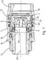
- figure 1 shows a breakaway coupling according to the invention in a longitudinal sectional view.
- the breakaway coupling comprises a first coupling part 3 and a second coupling part 4.
- the coupling parts are in figure 1 in an assembled state.
- the second coupling part 4 which in the present case is designed as a male coupling part, engages in the first coupling part 3, which is designed as a female coupling part.
- the coupling parts 3, 4 each have a fluid connection 13 for connection to a fluid line (not shown).
- the two coupling parts 3, 4 are fastened to one another with the aid of a locking ring 5, which engages in a locking ring receptacle arranged on an inner surface of the first coupling part 3 and in a further locking ring receptacle arranged on an outer surface of the second coupling part 4.
- a non-rotationally symmetrical locking ring 12 is arranged, which positively interacts with both coupling parts 3, 4 and on these Way relative rotation of the two coupling parts 3, 4 against each other prevented.
- the breakaway coupling also has an outlet protection valve 20 arranged in an end region 9 of the second coupling part 4 .
- the outlet protection valve 20 comprises a sealing body 14 and a valve seat 21.
- the sealing body 14 is connected to a return spring 15 which exerts a closing force on the sealing body 14 and thus urges it in the direction of a closed position.
- the sealing body 14 in the in figure 1 shown assembled state of the coupling parts 3, 4, the sealing body 14 is held by a hold-open element 16 in an open position.
- a front face of the hold-open element 16 pointing towards the second coupling part 4 presses against a counter-face of the sealing body 14 and thus holds it in the open position against the closing force. In this position, the fluid can flow through a channel formed inside the coupling parts 3,4.
- the valve seat 21 has a contact surface 24 for a sealing surface 26 of the sealing body 14 .
- a compensating element 25 which is arranged concentrically with respect to a longitudinal axis 22 of the valve seat and is materially connected to the contact surface 24 of the valve seat 21 .
- the compensating element 25 is made of acrylonitrile butadiene rubber (NBR) and has a Shore A hardness of 85.
- NBR acrylonitrile butadiene rubber
- the valve seat 21 is made of aluminum and the sealing body 14 and its sealing surface 26 are made of plastic. Valve seat 21 and sealing body 14 have a significantly greater hardness than the compensating element.
- the mean peak-to-valley height R z according to DIN EN ISO 4287:1984 of the material of the sealing body 14 is 4 ⁇ m in the present case.
- the compensating element 25 prevents direct contact between the material of the sealing body 14 and the material of the valve seat 21 in the area of the contact surface 24 .
- a guide for the sealing body 14 is formed by the inner wall surface of the breakaway coupling downstream of the valve seat 21, along which the sealing body 14 is movable. This guidance enables an angular deviation of more than 0.1° between an axial direction of the sealing body 14 and the longitudinal axis 22 of the valve seat 21.
- the locking ring 5 snaps out of the locking ring receptacle of the first and/or second coupling part, thus enabling a controlled and defined separation of the two coupling parts 3, 4 from one another.
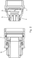
- figure 2 is the embodiment of figure 1 shown in a separated condition of the coupling parts.
- the front surface of the hold-open element 16 moves away from the counter surface of the sealing body 14, so that the sealing body 14 is moved into the closed position by the closing force exerted by the return spring 15.
- a sealing surface 26 of the sealing body 14 comes to rest on the compensating element 25 and the fluid channel of the second clutch part 4 is thereby closed.
- the above-described misalignment of the sealing body 14 relative to the longitudinal axis 22 can result in the sealing surface 26 not lying optimally on the valve seat 21 .
- the circumferential section that protrudes further in the longitudinal direction thus hits the contact surface 24 first.
- Due to the compensating element 25 arranged there, however, the soft material of the compensating element can be deformed at this point, so that the misalignment is compensated for and, despite the misalignment, there is a sealing closure between the sealing surface 26 of the sealing body 14 and the contact surface 24 of the valve seat 21.
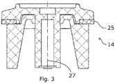
- figure 3 shows a side sectional view of a sealing body 14 of an alternative embodiment of a breakaway coupling according to the invention.
- the compensating element 25 is not on the valve seat 21 but, as in FIG figure 3 shown, arranged on the sealing body 14 .
- the sealing body has a circumferential groove in which the compensating element is inserted.
- the axial direction 27 of the sealing body 14 is illustrated.
Landscapes
- Engineering & Computer Science (AREA)
- General Engineering & Computer Science (AREA)
- Mechanical Engineering (AREA)
- Lift Valve (AREA)
- Quick-Acting Or Multi-Walled Pipe Joints (AREA)
- Joints Allowing Movement (AREA)
Applications Claiming Priority (2)
| Application Number | Priority Date | Filing Date | Title |
|---|---|---|---|
| EP19172437 | 2019-05-03 | ||
| PCT/EP2020/062276 WO2020225192A1 (de) | 2019-05-03 | 2020-05-04 | ABREIßKUPPLUNG MIT VERDREHSICHERUNG |
Publications (2)
| Publication Number | Publication Date |
|---|---|
| EP3963246A1 EP3963246A1 (de) | 2022-03-09 |
| EP3963246B1 true EP3963246B1 (de) | 2023-03-08 |
Family
ID=66397079
Family Applications (1)
| Application Number | Title | Priority Date | Filing Date |
|---|---|---|---|
| EP20722589.7A Active EP3963246B1 (de) | 2019-05-03 | 2020-05-04 | Abreisskupplung mit verdrehsicherung |
Country Status (12)
| Country | Link |
|---|---|
| US (1) | US11543063B2 (pl) |
| EP (1) | EP3963246B1 (pl) |
| CN (1) | CN113785153B (pl) |
| AU (1) | AU2020267822B2 (pl) |
| BR (1) | BR112021021560B1 (pl) |
| CA (1) | CA3138987A1 (pl) |
| CL (1) | CL2021002817A1 (pl) |
| DK (1) | DK3963246T3 (pl) |
| ES (1) | ES2942292T3 (pl) |
| PL (1) | PL3963246T3 (pl) |
| PT (1) | PT3963246T (pl) |
| WO (1) | WO2020225192A1 (pl) |
Families Citing this family (2)
| Publication number | Priority date | Publication date | Assignee | Title |
|---|---|---|---|---|
| US12344385B2 (en) * | 2020-07-18 | 2025-07-01 | Goodrich Corporation | Load adjustable and reusable mechanical restraint for aircraft evacuation slide/raft systems |
| CN112780854A (zh) * | 2021-01-28 | 2021-05-11 | 兰州凯宏中原石油科技有限公司 | 一种油田用油管防旋转连接件 |
Family Cites Families (17)
| Publication number | Priority date | Publication date | Assignee | Title |
|---|---|---|---|---|
| US3719194A (en) * | 1971-09-23 | 1973-03-06 | Wiggens E Inc | Breakaway coupling |
| US4674525A (en) * | 1985-08-16 | 1987-06-23 | Richards Industries, Inc. | Breakaway hose coupling device |
| US4763683A (en) * | 1987-09-21 | 1988-08-16 | Catlow, Inc. | Breakaway coupling for a coaxial fuel supply hose |
| US5018546A (en) | 1990-10-15 | 1991-05-28 | Helix Enterprises, Inc. | Fuel supply detachable coupling |
| US5228474A (en) | 1991-11-05 | 1993-07-20 | Precision General, Inc. | Flow system disconnect and method |
| US5360413A (en) * | 1991-12-06 | 1994-11-01 | Filtertek, Inc. | Needleless access device |
| AU1331595A (en) * | 1993-11-30 | 1995-06-19 | Medex, Inc. | Anti-reflux valve with environmental barrier |
| US5385331A (en) | 1994-03-15 | 1995-01-31 | Aeroquip Corporation | Valve assembly |
| US8141849B1 (en) * | 2001-04-16 | 2012-03-27 | Blume George H | Valve body and seal assembly |
| US6997181B2 (en) * | 2004-04-29 | 2006-02-14 | The Lighthouse For The Blind, Inc. | Personal hydration device |
| DE102005011601A1 (de) | 2005-03-08 | 2006-09-14 | Roman Seliger Gmbh | Abreißkupplung |
| DE202010009871U1 (de) | 2010-07-05 | 2011-08-02 | Erwin Weh | Hochdruckverbindung |
| ES2663602T3 (es) | 2011-06-01 | 2018-04-16 | Elaflex Hiby Tanktechnik Gmbh & Co. | Acoplamiento arrancable para un conducto de líquido |
| DE102012103061A1 (de) | 2012-03-23 | 2013-09-26 | Andreas von Keitz | Kupplung zum Anschluss fluidführender Leitungen |
| JP2014123293A (ja) | 2012-12-21 | 2014-07-03 | Panasonic Corp | 振動制御装置、電子機器、および振動制御方法 |
| DE102015014816B4 (de) | 2015-11-14 | 2018-01-18 | Audi Ag | Kupplungselement zum Verbinden fluidführender Leitungen sowie entsprechende Kupplungsanordnung |
| FR3071301B1 (fr) | 2017-09-15 | 2019-09-27 | Staubli Faverges | Coupe-circuit et installation de manutention de fluide sous pression comprenant un tel coupe-circuit |
-
2020
- 2020-05-04 PT PT207225897T patent/PT3963246T/pt unknown
- 2020-05-04 CN CN202080033180.7A patent/CN113785153B/zh active Active
- 2020-05-04 CA CA3138987A patent/CA3138987A1/en not_active Abandoned
- 2020-05-04 BR BR112021021560-3A patent/BR112021021560B1/pt active IP Right Grant
- 2020-05-04 PL PL20722589.7T patent/PL3963246T3/pl unknown
- 2020-05-04 ES ES20722589T patent/ES2942292T3/es active Active
- 2020-05-04 US US17/608,520 patent/US11543063B2/en active Active
- 2020-05-04 WO PCT/EP2020/062276 patent/WO2020225192A1/de not_active Ceased
- 2020-05-04 DK DK20722589.7T patent/DK3963246T3/da active
- 2020-05-04 EP EP20722589.7A patent/EP3963246B1/de active Active
- 2020-05-04 AU AU2020267822A patent/AU2020267822B2/en active Active
-
2021
- 2021-10-26 CL CL2021002817A patent/CL2021002817A1/es unknown
Also Published As
| Publication number | Publication date |
|---|---|
| CA3138987A1 (en) | 2020-11-12 |
| BR112021021560A2 (pt) | 2022-04-19 |
| PL3963246T3 (pl) | 2023-05-22 |
| CL2021002817A1 (es) | 2022-05-27 |
| CN113785153A (zh) | 2021-12-10 |
| US20220146030A1 (en) | 2022-05-12 |
| AU2020267822A1 (en) | 2022-01-06 |
| BR112021021560B1 (pt) | 2023-11-14 |
| DK3963246T3 (da) | 2023-04-17 |
| ES2942292T3 (es) | 2023-05-31 |
| WO2020225192A1 (de) | 2020-11-12 |
| US11543063B2 (en) | 2023-01-03 |
| EP3963246A1 (de) | 2022-03-09 |
| AU2020267822B2 (en) | 2022-11-24 |
| PT3963246T (pt) | 2023-03-31 |
| CN113785153B (zh) | 2022-10-11 |
Similar Documents
| Publication | Publication Date | Title |
|---|---|---|
| EP1688654B1 (de) | Vakuumventil | |
| DE60305236T2 (de) | Verbindungsvorrichtung zur Verbindung von zwei Rohren | |
| EP3293436B1 (de) | Kupplungseinrichtung zum verbinden mit einem schmiernippel | |
| EP3963246B1 (de) | Abreisskupplung mit verdrehsicherung | |
| EP3377796A1 (de) | Kupplungselement für eine kupplung zur verbindung von druckmittelleitungen | |
| EP1604071B1 (de) | Rückflussverhinderer | |
| DE3045215A1 (de) | Klappe | |
| DE2822982C2 (de) | Ventil | |
| WO2019238711A1 (de) | Zentrifuge | |
| EP3867550B1 (de) | Ventil, insbesondere rückschlagventil | |
| EP4390207B1 (de) | Kupplungsteil für eine hydraulikkupplung | |
| EP1632705A1 (de) | Drehbare und molchbare Leitungsverbindung | |
| EP3217050B1 (de) | Dichtungsanordnung für ein drehschieberventil | |
| EP2333354A1 (de) | Schraub- oder Nietverbindung | |
| WO2005093302A9 (de) | Druckbegrenzungsventil | |
| EP1095225A1 (de) | Schubgesicherte steckmuffenverbindung | |
| EP0386332B1 (de) | Entleerungsvorrichtung für Behälter | |
| EP4175889A1 (de) | Einsatzteil für eine verpackungsöffnung und verfahren zum einsetzen eines einsatzteils in eine verpackungsöffnung | |
| DE3003480C2 (pl) | ||
| DE202009010326U1 (de) | Anordnung zur Abdichtung von Leitungen, Armaturen oder Aggregaten | |
| EP4124787B1 (de) | Mehrteiliges druckstueck für ein membranventil | |
| AT527945B1 (de) | Steckverbinder zum strömungstechnischen Verbinden eines fluidführenden Bauteils mit einer Fluidleitung | |
| EP1447601B1 (de) | Doppelsitzventil | |
| EP0711940A1 (de) | Verfahren zum leckagefreien Schalten eines Doppelsitzventils und Dichtungsanordnung zur Durchführung des Verfahrens | |
| EP4660493A1 (de) | Spannbaugruppe und prozessventil |
Legal Events
| Date | Code | Title | Description |
|---|---|---|---|
| STAA | Information on the status of an ep patent application or granted ep patent |
Free format text: STATUS: UNKNOWN |
|
| STAA | Information on the status of an ep patent application or granted ep patent |
Free format text: STATUS: THE INTERNATIONAL PUBLICATION HAS BEEN MADE |
|
| PUAI | Public reference made under article 153(3) epc to a published international application that has entered the european phase |
Free format text: ORIGINAL CODE: 0009012 |
|
| STAA | Information on the status of an ep patent application or granted ep patent |
Free format text: STATUS: REQUEST FOR EXAMINATION WAS MADE |
|
| 17P | Request for examination filed |
Effective date: 20211022 |
|
| AK | Designated contracting states |
Kind code of ref document: A1 Designated state(s): AL AT BE BG CH CY CZ DE DK EE ES FI FR GB GR HR HU IE IS IT LI LT LU LV MC MK MT NL NO PL PT RO RS SE SI SK SM TR |
|
| DAV | Request for validation of the european patent (deleted) | ||
| DAX | Request for extension of the european patent (deleted) | ||
| GRAP | Despatch of communication of intention to grant a patent |
Free format text: ORIGINAL CODE: EPIDOSNIGR1 |
|
| STAA | Information on the status of an ep patent application or granted ep patent |
Free format text: STATUS: GRANT OF PATENT IS INTENDED |
|
| INTG | Intention to grant announced |
Effective date: 20221209 |
|
| GRAS | Grant fee paid |
Free format text: ORIGINAL CODE: EPIDOSNIGR3 |
|
| GRAA | (expected) grant |
Free format text: ORIGINAL CODE: 0009210 |
|
| STAA | Information on the status of an ep patent application or granted ep patent |
Free format text: STATUS: THE PATENT HAS BEEN GRANTED |
|
| AK | Designated contracting states |
Kind code of ref document: B1 Designated state(s): AL AT BE BG CH CY CZ DE DK EE ES FI FR GB GR HR HU IE IS IT LI LT LU LV MC MK MT NL NO PL PT RO RS SE SI SK SM TR |
|
| REG | Reference to a national code |
Ref country code: CH Ref legal event code: EP Ref country code: AT Ref legal event code: REF Ref document number: 1552775 Country of ref document: AT Kind code of ref document: T Effective date: 20230315 |
|
| REG | Reference to a national code |
Ref country code: IE Ref legal event code: FG4D Free format text: LANGUAGE OF EP DOCUMENT: GERMAN |
|
| REG | Reference to a national code |
Ref country code: DE Ref legal event code: R096 Ref document number: 502020002712 Country of ref document: DE |
|
| REG | Reference to a national code |
Ref country code: PT Ref legal event code: SC4A Ref document number: 3963246 Country of ref document: PT Date of ref document: 20230331 Kind code of ref document: T Free format text: AVAILABILITY OF NATIONAL TRANSLATION Effective date: 20230327 |
|
| REG | Reference to a national code |
Ref country code: DK Ref legal event code: T3 Effective date: 20230412 |
|
| REG | Reference to a national code |
Ref country code: NL Ref legal event code: FP |
|
| REG | Reference to a national code |
Ref country code: SE Ref legal event code: TRGR |
|
| REG | Reference to a national code |
Ref country code: ES Ref legal event code: FG2A Ref document number: 2942292 Country of ref document: ES Kind code of ref document: T3 Effective date: 20230531 Ref country code: GR Ref legal event code: EP Ref document number: 20230400572 Country of ref document: GR Effective date: 20230510 |
|
| P01 | Opt-out of the competence of the unified patent court (upc) registered |
Effective date: 20230516 |
|
| REG | Reference to a national code |
Ref country code: LT Ref legal event code: MG9D |
|
| PG25 | Lapsed in a contracting state [announced via postgrant information from national office to epo] |
Ref country code: RS Free format text: LAPSE BECAUSE OF FAILURE TO SUBMIT A TRANSLATION OF THE DESCRIPTION OR TO PAY THE FEE WITHIN THE PRESCRIBED TIME-LIMIT Effective date: 20230308 Ref country code: NO Free format text: LAPSE BECAUSE OF FAILURE TO SUBMIT A TRANSLATION OF THE DESCRIPTION OR TO PAY THE FEE WITHIN THE PRESCRIBED TIME-LIMIT Effective date: 20230608 Ref country code: LV Free format text: LAPSE BECAUSE OF FAILURE TO SUBMIT A TRANSLATION OF THE DESCRIPTION OR TO PAY THE FEE WITHIN THE PRESCRIBED TIME-LIMIT Effective date: 20230308 Ref country code: LT Free format text: LAPSE BECAUSE OF FAILURE TO SUBMIT A TRANSLATION OF THE DESCRIPTION OR TO PAY THE FEE WITHIN THE PRESCRIBED TIME-LIMIT Effective date: 20230308 Ref country code: HR Free format text: LAPSE BECAUSE OF FAILURE TO SUBMIT A TRANSLATION OF THE DESCRIPTION OR TO PAY THE FEE WITHIN THE PRESCRIBED TIME-LIMIT Effective date: 20230308 |
|
| PG25 | Lapsed in a contracting state [announced via postgrant information from national office to epo] |
Ref country code: FI Free format text: LAPSE BECAUSE OF FAILURE TO SUBMIT A TRANSLATION OF THE DESCRIPTION OR TO PAY THE FEE WITHIN THE PRESCRIBED TIME-LIMIT Effective date: 20230308 |
|
| PG25 | Lapsed in a contracting state [announced via postgrant information from national office to epo] |
Ref country code: SM Free format text: LAPSE BECAUSE OF FAILURE TO SUBMIT A TRANSLATION OF THE DESCRIPTION OR TO PAY THE FEE WITHIN THE PRESCRIBED TIME-LIMIT Effective date: 20230308 Ref country code: RO Free format text: LAPSE BECAUSE OF FAILURE TO SUBMIT A TRANSLATION OF THE DESCRIPTION OR TO PAY THE FEE WITHIN THE PRESCRIBED TIME-LIMIT Effective date: 20230308 Ref country code: EE Free format text: LAPSE BECAUSE OF FAILURE TO SUBMIT A TRANSLATION OF THE DESCRIPTION OR TO PAY THE FEE WITHIN THE PRESCRIBED TIME-LIMIT Effective date: 20230308 Ref country code: CZ Free format text: LAPSE BECAUSE OF FAILURE TO SUBMIT A TRANSLATION OF THE DESCRIPTION OR TO PAY THE FEE WITHIN THE PRESCRIBED TIME-LIMIT Effective date: 20230308 |
|
| PG25 | Lapsed in a contracting state [announced via postgrant information from national office to epo] |
Ref country code: SK Free format text: LAPSE BECAUSE OF FAILURE TO SUBMIT A TRANSLATION OF THE DESCRIPTION OR TO PAY THE FEE WITHIN THE PRESCRIBED TIME-LIMIT Effective date: 20230308 Ref country code: IS Free format text: LAPSE BECAUSE OF FAILURE TO SUBMIT A TRANSLATION OF THE DESCRIPTION OR TO PAY THE FEE WITHIN THE PRESCRIBED TIME-LIMIT Effective date: 20230708 |
|
| REG | Reference to a national code |
Ref country code: DE Ref legal event code: R097 Ref document number: 502020002712 Country of ref document: DE |
|
| REG | Reference to a national code |
Ref country code: CH Ref legal event code: PL |
|
| PLBE | No opposition filed within time limit |
Free format text: ORIGINAL CODE: 0009261 |
|
| STAA | Information on the status of an ep patent application or granted ep patent |
Free format text: STATUS: NO OPPOSITION FILED WITHIN TIME LIMIT |
|
| PG25 | Lapsed in a contracting state [announced via postgrant information from national office to epo] |
Ref country code: MC Free format text: LAPSE BECAUSE OF FAILURE TO SUBMIT A TRANSLATION OF THE DESCRIPTION OR TO PAY THE FEE WITHIN THE PRESCRIBED TIME-LIMIT Effective date: 20230308 |
|
| REG | Reference to a national code |
Ref country code: BE Ref legal event code: MM Effective date: 20230531 |
|
| PG25 | Lapsed in a contracting state [announced via postgrant information from national office to epo] |
Ref country code: SI Free format text: LAPSE BECAUSE OF FAILURE TO SUBMIT A TRANSLATION OF THE DESCRIPTION OR TO PAY THE FEE WITHIN THE PRESCRIBED TIME-LIMIT Effective date: 20230308 Ref country code: MC Free format text: LAPSE BECAUSE OF FAILURE TO SUBMIT A TRANSLATION OF THE DESCRIPTION OR TO PAY THE FEE WITHIN THE PRESCRIBED TIME-LIMIT Effective date: 20230308 Ref country code: LU Free format text: LAPSE BECAUSE OF NON-PAYMENT OF DUE FEES Effective date: 20230504 Ref country code: LI Free format text: LAPSE BECAUSE OF NON-PAYMENT OF DUE FEES Effective date: 20230531 Ref country code: CH Free format text: LAPSE BECAUSE OF NON-PAYMENT OF DUE FEES Effective date: 20230531 |
|
| 26N | No opposition filed |
Effective date: 20231211 |
|
| REG | Reference to a national code |
Ref country code: IE Ref legal event code: MM4A |
|
| PG25 | Lapsed in a contracting state [announced via postgrant information from national office to epo] |
Ref country code: IE Free format text: LAPSE BECAUSE OF NON-PAYMENT OF DUE FEES Effective date: 20230504 |
|
| PG25 | Lapsed in a contracting state [announced via postgrant information from national office to epo] |
Ref country code: IE Free format text: LAPSE BECAUSE OF NON-PAYMENT OF DUE FEES Effective date: 20230504 |
|
| PG25 | Lapsed in a contracting state [announced via postgrant information from national office to epo] |
Ref country code: BE Free format text: LAPSE BECAUSE OF NON-PAYMENT OF DUE FEES Effective date: 20230531 |
|
| PG25 | Lapsed in a contracting state [announced via postgrant information from national office to epo] |
Ref country code: BG Free format text: LAPSE BECAUSE OF FAILURE TO SUBMIT A TRANSLATION OF THE DESCRIPTION OR TO PAY THE FEE WITHIN THE PRESCRIBED TIME-LIMIT Effective date: 20230308 |
|
| PG25 | Lapsed in a contracting state [announced via postgrant information from national office to epo] |
Ref country code: BG Free format text: LAPSE BECAUSE OF FAILURE TO SUBMIT A TRANSLATION OF THE DESCRIPTION OR TO PAY THE FEE WITHIN THE PRESCRIBED TIME-LIMIT Effective date: 20230308 |
|
| PGFP | Annual fee paid to national office [announced via postgrant information from national office to epo] |
Ref country code: NL Payment date: 20250522 Year of fee payment: 6 |
|
| PGFP | Annual fee paid to national office [announced via postgrant information from national office to epo] |
Ref country code: DE Payment date: 20250526 Year of fee payment: 6 Ref country code: PL Payment date: 20250430 Year of fee payment: 6 |
|
| PGFP | Annual fee paid to national office [announced via postgrant information from national office to epo] |
Ref country code: GB Payment date: 20250522 Year of fee payment: 6 Ref country code: ES Payment date: 20250616 Year of fee payment: 6 Ref country code: DK Payment date: 20250521 Year of fee payment: 6 |
|
| PGFP | Annual fee paid to national office [announced via postgrant information from national office to epo] |
Ref country code: IT Payment date: 20250530 Year of fee payment: 6 |
|
| PGFP | Annual fee paid to national office [announced via postgrant information from national office to epo] |
Ref country code: PT Payment date: 20250429 Year of fee payment: 6 |
|
| PGFP | Annual fee paid to national office [announced via postgrant information from national office to epo] |
Ref country code: FR Payment date: 20250526 Year of fee payment: 6 |
|
| PGFP | Annual fee paid to national office [announced via postgrant information from national office to epo] |
Ref country code: GR Payment date: 20250519 Year of fee payment: 6 |
|
| PGFP | Annual fee paid to national office [announced via postgrant information from national office to epo] |
Ref country code: AT Payment date: 20250519 Year of fee payment: 6 |
|
| PG25 | Lapsed in a contracting state [announced via postgrant information from national office to epo] |
Ref country code: CY Free format text: LAPSE BECAUSE OF FAILURE TO SUBMIT A TRANSLATION OF THE DESCRIPTION OR TO PAY THE FEE WITHIN THE PRESCRIBED TIME-LIMIT; INVALID AB INITIO Effective date: 20200504 |
|
| PGFP | Annual fee paid to national office [announced via postgrant information from national office to epo] |
Ref country code: TR Payment date: 20250428 Year of fee payment: 6 |
|
| PGFP | Annual fee paid to national office [announced via postgrant information from national office to epo] |
Ref country code: SE Payment date: 20250522 Year of fee payment: 6 |
|
| PG25 | Lapsed in a contracting state [announced via postgrant information from national office to epo] |
Ref country code: HU Free format text: LAPSE BECAUSE OF FAILURE TO SUBMIT A TRANSLATION OF THE DESCRIPTION OR TO PAY THE FEE WITHIN THE PRESCRIBED TIME-LIMIT; INVALID AB INITIO Effective date: 20200504 |