EP3962824B1 - Endstück für einen behälter mit verbesserter transportfähigkeit und behälter mit dem endstück - Google Patents
Endstück für einen behälter mit verbesserter transportfähigkeit und behälter mit dem endstück Download PDFInfo
- Publication number
- EP3962824B1 EP3962824B1 EP20730103.7A EP20730103A EP3962824B1 EP 3962824 B1 EP3962824 B1 EP 3962824B1 EP 20730103 A EP20730103 A EP 20730103A EP 3962824 B1 EP3962824 B1 EP 3962824B1
- Authority
- EP
- European Patent Office
- Prior art keywords
- tab
- extension
- bead
- positive
- depression
- Prior art date
- Legal status (The legal status is an assumption and is not a legal conclusion. Google has not performed a legal analysis and makes no representation as to the accuracy of the status listed.)
- Active
Links
Images


Classifications
-
- B—PERFORMING OPERATIONS; TRANSPORTING
- B65—CONVEYING; PACKING; STORING; HANDLING THIN OR FILAMENTARY MATERIAL
- B65D—CONTAINERS FOR STORAGE OR TRANSPORT OF ARTICLES OR MATERIALS, e.g. BAGS, BARRELS, BOTTLES, BOXES, CANS, CARTONS, CRATES, DRUMS, JARS, TANKS, HOPPERS, FORWARDING CONTAINERS; ACCESSORIES, CLOSURES, OR FITTINGS THEREFOR; PACKAGING ELEMENTS; PACKAGES
- B65D17/00—Rigid or semi-rigid containers specially constructed to be opened by cutting or piercing, or by tearing of frangible members or portions
- B65D17/28—Rigid or semi-rigid containers specially constructed to be opened by cutting or piercing, or by tearing of frangible members or portions at lines or points of weakness
- B65D17/401—Rigid or semi-rigid containers specially constructed to be opened by cutting or piercing, or by tearing of frangible members or portions at lines or points of weakness characterised by having the line of weakness provided in an end wall
- B65D17/4011—Rigid or semi-rigid containers specially constructed to be opened by cutting or piercing, or by tearing of frangible members or portions at lines or points of weakness characterised by having the line of weakness provided in an end wall for opening completely by means of a tearing tab
-
- B—PERFORMING OPERATIONS; TRANSPORTING
- B65—CONVEYING; PACKING; STORING; HANDLING THIN OR FILAMENTARY MATERIAL
- B65D—CONTAINERS FOR STORAGE OR TRANSPORT OF ARTICLES OR MATERIALS, e.g. BAGS, BARRELS, BOTTLES, BOXES, CANS, CARTONS, CRATES, DRUMS, JARS, TANKS, HOPPERS, FORWARDING CONTAINERS; ACCESSORIES, CLOSURES, OR FITTINGS THEREFOR; PACKAGING ELEMENTS; PACKAGES
- B65D2517/00—Containers specially constructed to be opened by cutting, piercing or tearing of wall portions, e.g. preserving cans or tins
- B65D2517/0001—Details
- B65D2517/001—Action for opening container
- B65D2517/0013—Action for opening container pull-out tear panel, e.g. by means of a tear-tab
-
- B—PERFORMING OPERATIONS; TRANSPORTING
- B65—CONVEYING; PACKING; STORING; HANDLING THIN OR FILAMENTARY MATERIAL
- B65D—CONTAINERS FOR STORAGE OR TRANSPORT OF ARTICLES OR MATERIALS, e.g. BAGS, BARRELS, BOTTLES, BOXES, CANS, CARTONS, CRATES, DRUMS, JARS, TANKS, HOPPERS, FORWARDING CONTAINERS; ACCESSORIES, CLOSURES, OR FITTINGS THEREFOR; PACKAGING ELEMENTS; PACKAGES
- B65D2517/00—Containers specially constructed to be opened by cutting, piercing or tearing of wall portions, e.g. preserving cans or tins
- B65D2517/0001—Details
- B65D2517/001—Action for opening container
- B65D2517/0016—Action for opening container pivot tab, push-down and pull-out tear panel
-
- B—PERFORMING OPERATIONS; TRANSPORTING
- B65—CONVEYING; PACKING; STORING; HANDLING THIN OR FILAMENTARY MATERIAL
- B65D—CONTAINERS FOR STORAGE OR TRANSPORT OF ARTICLES OR MATERIALS, e.g. BAGS, BARRELS, BOTTLES, BOXES, CANS, CARTONS, CRATES, DRUMS, JARS, TANKS, HOPPERS, FORWARDING CONTAINERS; ACCESSORIES, CLOSURES, OR FITTINGS THEREFOR; PACKAGING ELEMENTS; PACKAGES
- B65D2517/00—Containers specially constructed to be opened by cutting, piercing or tearing of wall portions, e.g. preserving cans or tins
- B65D2517/0001—Details
- B65D2517/0058—Other details of container end panel
- B65D2517/0068—Ribs or projections in container end panel
- B65D2517/007—Ribs or projections in container end panel located within tear-out/push-in panel
-
- B—PERFORMING OPERATIONS; TRANSPORTING
- B65—CONVEYING; PACKING; STORING; HANDLING THIN OR FILAMENTARY MATERIAL
- B65D—CONTAINERS FOR STORAGE OR TRANSPORT OF ARTICLES OR MATERIALS, e.g. BAGS, BARRELS, BOTTLES, BOXES, CANS, CARTONS, CRATES, DRUMS, JARS, TANKS, HOPPERS, FORWARDING CONTAINERS; ACCESSORIES, CLOSURES, OR FITTINGS THEREFOR; PACKAGING ELEMENTS; PACKAGES
- B65D2517/00—Containers specially constructed to be opened by cutting, piercing or tearing of wall portions, e.g. preserving cans or tins
- B65D2517/0001—Details
- B65D2517/0058—Other details of container end panel
- B65D2517/0068—Ribs or projections in container end panel
- B65D2517/0071—Ribs or projections in container end panel located externally of tear-out/push-in panel or preformed opening
-
- B—PERFORMING OPERATIONS; TRANSPORTING
- B65—CONVEYING; PACKING; STORING; HANDLING THIN OR FILAMENTARY MATERIAL
- B65D—CONTAINERS FOR STORAGE OR TRANSPORT OF ARTICLES OR MATERIALS, e.g. BAGS, BARRELS, BOTTLES, BOXES, CANS, CARTONS, CRATES, DRUMS, JARS, TANKS, HOPPERS, FORWARDING CONTAINERS; ACCESSORIES, CLOSURES, OR FITTINGS THEREFOR; PACKAGING ELEMENTS; PACKAGES
- B65D2517/00—Containers specially constructed to be opened by cutting, piercing or tearing of wall portions, e.g. preserving cans or tins
- B65D2517/0001—Details
- B65D2517/0058—Other details of container end panel
- B65D2517/0074—Local recess in container end panel
- B65D2517/0079—Local recess in container end panel located beneath tab hand grip to facilitate initial lifting
-
- B—PERFORMING OPERATIONS; TRANSPORTING
- B65—CONVEYING; PACKING; STORING; HANDLING THIN OR FILAMENTARY MATERIAL
- B65D—CONTAINERS FOR STORAGE OR TRANSPORT OF ARTICLES OR MATERIALS, e.g. BAGS, BARRELS, BOTTLES, BOXES, CANS, CARTONS, CRATES, DRUMS, JARS, TANKS, HOPPERS, FORWARDING CONTAINERS; ACCESSORIES, CLOSURES, OR FITTINGS THEREFOR; PACKAGING ELEMENTS; PACKAGES
- B65D2543/00—Lids or covers essentially for box-like containers
- B65D2543/00009—Details of lids or covers for rigid or semi-rigid containers
- B65D2543/00018—Overall construction of the lid
- B65D2543/00027—Stackable lids or covers
-
- B—PERFORMING OPERATIONS; TRANSPORTING
- B65—CONVEYING; PACKING; STORING; HANDLING THIN OR FILAMENTARY MATERIAL
- B65D—CONTAINERS FOR STORAGE OR TRANSPORT OF ARTICLES OR MATERIALS, e.g. BAGS, BARRELS, BOTTLES, BOXES, CANS, CARTONS, CRATES, DRUMS, JARS, TANKS, HOPPERS, FORWARDING CONTAINERS; ACCESSORIES, CLOSURES, OR FITTINGS THEREFOR; PACKAGING ELEMENTS; PACKAGES
- B65D2543/00—Lids or covers essentially for box-like containers
- B65D2543/00009—Details of lids or covers for rigid or semi-rigid containers
- B65D2543/00018—Overall construction of the lid
- B65D2543/00064—Shape of the outer periphery
- B65D2543/0012—Shape of the outer periphery having straight sides, e.g. with curved corners
- B65D2543/00129—Shape of the outer periphery having straight sides, e.g. with curved corners two straight sides and at least one curved side
- B65D2543/00148—Shape of the outer periphery having straight sides, e.g. with curved corners two straight sides and at least one curved side with two curved sides
-
- B—PERFORMING OPERATIONS; TRANSPORTING
- B65—CONVEYING; PACKING; STORING; HANDLING THIN OR FILAMENTARY MATERIAL
- B65D—CONTAINERS FOR STORAGE OR TRANSPORT OF ARTICLES OR MATERIALS, e.g. BAGS, BARRELS, BOTTLES, BOXES, CANS, CARTONS, CRATES, DRUMS, JARS, TANKS, HOPPERS, FORWARDING CONTAINERS; ACCESSORIES, CLOSURES, OR FITTINGS THEREFOR; PACKAGING ELEMENTS; PACKAGES
- B65D2543/00—Lids or covers essentially for box-like containers
- B65D2543/00009—Details of lids or covers for rigid or semi-rigid containers
- B65D2543/00018—Overall construction of the lid
- B65D2543/00259—Materials used
- B65D2543/00277—Metal
-
- B—PERFORMING OPERATIONS; TRANSPORTING
- B65—CONVEYING; PACKING; STORING; HANDLING THIN OR FILAMENTARY MATERIAL
- B65D—CONTAINERS FOR STORAGE OR TRANSPORT OF ARTICLES OR MATERIALS, e.g. BAGS, BARRELS, BOTTLES, BOXES, CANS, CARTONS, CRATES, DRUMS, JARS, TANKS, HOPPERS, FORWARDING CONTAINERS; ACCESSORIES, CLOSURES, OR FITTINGS THEREFOR; PACKAGING ELEMENTS; PACKAGES
- B65D2543/00—Lids or covers essentially for box-like containers
- B65D2543/00009—Details of lids or covers for rigid or semi-rigid containers
- B65D2543/00342—Central part of the lid
- B65D2543/00398—Reinforcing ribs in the central part of the closure
- B65D2543/00416—Reinforcing ribs in the central part of the closure circular
-
- B—PERFORMING OPERATIONS; TRANSPORTING
- B65—CONVEYING; PACKING; STORING; HANDLING THIN OR FILAMENTARY MATERIAL
- B65D—CONTAINERS FOR STORAGE OR TRANSPORT OF ARTICLES OR MATERIALS, e.g. BAGS, BARRELS, BOTTLES, BOXES, CANS, CARTONS, CRATES, DRUMS, JARS, TANKS, HOPPERS, FORWARDING CONTAINERS; ACCESSORIES, CLOSURES, OR FITTINGS THEREFOR; PACKAGING ELEMENTS; PACKAGES
- B65D2543/00—Lids or covers essentially for box-like containers
- B65D2543/00009—Details of lids or covers for rigid or semi-rigid containers
- B65D2543/00824—Means for facilitating removing of the closure
- B65D2543/00861—Non-integral tabs, tongues, handles or similar
- B65D2543/0087—Non-integral tabs, tongues, handles or similar outside of the lid
Definitions
- the invention relates to an end for a container, specifically to an easy open end comprising a pull-tab. And it relates to a stack of at least two ends, a container comprising such end as well as a stack of at least two such containers.
- Containers with easy open ends are e.g. used for CLUB cans. These containers, including the end, are typically made of sheet metal. Foodstuff, e.g. seafood, is commonly housed in these containers.
- the containers and the corresponding ends are provided to a customer, i.e. food manufacturer, separately in large quantities.
- the customer can fill the container with foodstuff, e.g. seafood, and close the opening of the container with the end (the lid), e.g. by a double seam.
- CA 967 898 A discloses a lid (end) according to the preamble of claim 1 and having a roughly triangular shaped stabilizing bead opposite to the tab side of the lid.
- the prior art lid or end is round.
- the end for a container comprises a central panel, a tab, a depression and at least one bead.
- the end comprises a stabilizing bead that is shaped in the end, wherein the stabilizing bead has an extension sPB in the positive z-direction; a height of the extension sT of the tab in the positive z direction is equal to a height of the extension sPB of the stabilizing bead in the positive z direction ⁇ 0.3 mm.
- the at least one first bead (called “the bead” hereinafter) is shaped in the end and extends in the negative z-direction, thereby having an extension (and a height thereof).
- the central panel defines an x-y-plane and a z-direction is perpendicular to the x-y-plane.
- the tab is attached to the end, e.g. via a rivet.
- the tab is attached to the central panel.
- the tab comprises a front portion and a rear portion, and the tab extends in positive z-direction.
- the depression is formed in the end, preferably in the central panel of the end.
- the depression extends in the negative z-direction and is shaped and positioned to allow a human finger to reach at least partially below the rear portion of the tab.
- the at least one bead is shaped in the end, preferably in the central panel of the end.
- the bead extends in the negative z-direction.
- the at least one bead may be positioned or may be formed in the end such that no portion of the second bead overlaps with a portion of the tab.
- the second bead may be positioned or may be formed in the end such that a distance between the tab and the second bead is at least 5 mm, at least 10 mm, at least 15 mm, or at least 20 mm.
- the distance between the tab and the second bead may be the shortest distance between portions of the tab and the second bead.
- the x-y-plane is a reference plane for claimed and described extensions of elements.
- An extension is measured as a distance in z-direction between the x-y-plane and a second plane that is defined by the respective element itself.
- the x-y-plane defined by the central panel is parallel ⁇ 1.5 °, more preferably ⁇ 1.0 °, most preferred ⁇ 0.5 °, to a flat surface when the end is positioned on the flat surface.
- the flat surface may be a conveyor belt.
- the end may be an easy-open-end comprising a tab, preferably a pull-tab, and a score line as a mechanically weakened portion in the end.
- the tab of the end can be attached to the central panel of the end such that a lifting movement of a rear portion of the tab forces a front portion (nose portion) of the tab towards the score line of the end in order to break a portion of the end.
- a consumer may then pull the tab away from the container in order to remove a large portion of the end. Thereby, the container can be opened and the filling of the container can be accessed.
- the central panel of the end may be the largest portion (by area) of the end extending in the same plane, e.g. an x-y-plane.
- the tab may be a pull-tab comprising a finger hole for allowing a human finger to reach through the tab.
- the tab may be attached to the central panel or to another portion of the end e.g. via rivet.
- the tab extends between 1.4 mm and 2.5 mm, preferably between 1.7 mm and 2.2 mm, more preferably between 1.8 mm and 2.0 mm, in a positive z-direction that is perpendicular to the x-y-plane of the central panel. It is especially preferred that the tab extends about 1.95 mm in the positive z-direction.
- the extension is measured as the distance in z-direction between the x-y-plane that is defined by the central panel and a second plane that is defined by the respective element.
- the second plane is parallel to the x-y-plane and is defined by a portion of the respective element that has the greatest distance from the x-y-plane in the z-direction.
- the extension of an element may be the actual/physical height of the respective element in z-direction.
- the respective element is attached to the central panel (e.g. the tab) or may be formed in the central panel (e.g. the bead, the bulge, the depression, the second or stabilizing bead). This applies the general rule of the preceding paragraph to the specific case in which the respective element is associated with the central panel.
- the (first) bead extends between 0.5 mm and 4.0 mm, preferably between 1.0 mm and 2.5 mm, more preferably between 1.2 mm and 1.5 mm, in the negative z-direction that is perpendicular to the x-y-plane of the central panel.
- the extension of the bead may be equal to the extension of the depression in the negative z-direction ⁇ 1.5 mm, preferably ⁇ 1.0 mm, more preferably ⁇ 0.5 mm, most preferably ⁇ 0.2 mm. It is especially preferred that the extension of the bead is substantially equal to the extension of the depression in the negative z-direction.
- the depression can be substantially circular shaped.
- the depression can have an area between 80 mm 2 and 500 mm 2 , preferably between 90 mm 2 and 300 mm 2 .
- a portion of the depression may overlap with a portion of the tab, specifically with the rear portion of the tab.
- the depression extends between 0.5 mm and 4.0 mm, preferably between 1.0 mm and 2.5 mm, more preferably between 1.2 mm and 1.5 mm, in the negative z-direction that is perpendicular to the x-y-plane of the central panel. It is especially preferred that the depression extends about 1.25 mm in the negative z-direction.
- the end comprises a second bead (also called stabilizing bead herein).
- the stabilizing bead is shaped in the end and extends in the positive z-direction. It is preferred that the stabilizing bead is shaped in the central panel of the end and extends in the positive z-direction.
- the stabilizing bead may be substantially c-shaped, substantially circular shaped, substantially oval shaped or substantially straight shaped in the end, preferably in the central plane of the end.
- the stabilizing bead may have an elongated shape.
- the stabilizing bead may not be dome-shaped, especially may not be dome-shaped with a circular basic shape.
- the stabilizing bead may extend over a length of at least 5 mm, at least 10 mm, at least 15 mm, at least 20 mm, or at least 30 mm, when the stabilizing bead has an elongated shape.
- the stabilizing bead may fully surround a portion of the end or may not fully surround a portion of the end.
- the stabilizing bead extends between 0.4 mm and 2.5 mm, preferably between 0.5 mm and 1.5 mm, more preferably between 0.6 mm and 1.0 mm, in a positive z-direction that is perpendicular to the x-y-plane of the central panel. Specifically, the stabilizing bead extends about 0.8 mm in the positive z-direction.
- the extension of the tab in the positive z-direction can be equal to the extension of the stabilizing bead in the positive z-direction ⁇ 1.5 mm.
- the extension of the tab in the positive z-direction is equal to the extension of the stabilizing bead in the positive z-direction ⁇ 0.75 mm or ⁇ 0.3 mm.
- the extension of the stabilizing bead is substantially equal to the extension of the tab in the positive z-direction. This is named the height of the extension of this bead.
- the extension of the depression in the negative z-direction may be equal to the extension of the tab in the positive z-direction ⁇ 1.0 mm, preferably ⁇ 0.5 mm. It is especially preferred that the extension of the depression in the negative z-direction is equal to the extension of the tab in the positive z-direction ⁇ 0.2 mm.
- the extension of the depression in the negative z-direction is equal to the extension of the stabilizing bead in the positive z-direction ⁇ 2.0 mm, preferably ⁇ 1.2 mm.
- the extension of the depression in the negative z-direction is equal to the extension of the stabilizing bead in the positive z-direction ⁇ 0.8 mm.
- the bead can be at least partially surrounded by the stabilizing bead, fully surrounded by the second stabilizing bead or not surrounded by the second stabilizing bead, preferably in a plane.
- depression is not (fully) surrounded by the stabilizing bead, preferably in a plane.
- the end may comprise at least one bulge, preferably at least two bulges.
- the bulge may be shaped in the end and may extend in the positive z-direction.
- the at least one bulge may be positioned in the proximity of the tab and associated with the tab.
- the at least one bulge is located in the proximity of an outer side of the tab that extends between the front portion and the rear portion of the tab.
- a first bulge is located in the proximity of a first outer side of the tab that extends between the front portion and the rear portion of the tab and a second bulge is located in the proximity of a second outer side of the tab that extends between the front portion and the rear portion of the tab.
- the extension of the at least one bulge in the positive z-direction may be equal to the extension of the tab in the positive z-direction ⁇ 2.0 mm, preferably ⁇ 1.5 mm. Specifically, the extension of the bulge in the positive z-direction is equal to the extension of the tab in the positive z-direction ⁇ 1.0 mm.
- the extension of the at least one bulge may be lower or equal to the extension of the tab in the positive z-direction.
- the extension of the bulge is at most 1.5 mm, more preferably at most 1.2 mm, even more preferably at most 0.9 mm, smaller than the extension of the tab in the positive z-direction. It is especially preferred that the extension of the at least one bulge is substantially equal to the extension of the tab in the positive z-direction.
- the extension of the at least one bulge may be equal to the extension of the stabilizing bead ⁇ 2.0 mm, preferably ⁇ 1.2 mm, more preferably ⁇ 0.6 mm, in the positive z-direction.
- the extension of the at least one bulge in the positive z-direction may also be equal to the extension of the depression in the negative z-direction ⁇ 2.0 mm, preferably ⁇ 1.2 mm, more preferably ⁇ 0.6 mm, even more preferably ⁇ 0.2 mm.
- the at least one bulge (or at least two bulges) may have a non-round basic shape.
- the at least one bulge may be positioned and may be configured to prevent a possible rotation of the tab (about the rivet), especially prior to actuating the tab or prior to open the end.
- the at least one bulge may be positioned and may be configured to reduce a rotation of the tab (about the rivet), especially prior to actuating the tab or prior to open the end.
- the end of the container may comprise metal, preferably steel or aluminum.
- the end may also be made of metal, preferably steel or aluminum.
- a stack of at least two ends comprises any of the herein disclosed ends, wherein the ends in the stack of ends are same ends.
- a container comprises an end as disclosed herein and a container body.
- the container body of the container may be a one-piece container body.
- the end may be seamed to the container body, specifically via a double seam.
- the container body may also be a two-piece container body that may comprise a container wall and a container bottom, wherein the bottom may be seamed to a container wall and the end may be seamed to the container wall.
- the container body may comprise metal, preferably steel or aluminum.
- the container body may also be made of metal, preferably steel or aluminum.
- the container comprises food, such as seafood or vegetables.
- At least two containers of claims 13 or 14 are stacked for e.g. transportation of filled containers or presentation of the containers at a point of sale.
- the stacked containers are the same containers comprising same elements, specifically same container bodies and same ends. These stacked containers may be parallel ⁇ 2.0 °, specifically the central panels of the containers may be parallel ⁇ 2.0 °.
- (the central panels of) the two containers are parallel ⁇ 1.5 °, ⁇ 1.0 °, or even ⁇ 0.5 °. Thereby, an increased stability of the stack is achieved.
- the lower surfaces of the containers may be parallel ⁇ 2.0 °, preferably ⁇ 1.0 °, more preferably ⁇ 0.5 °.
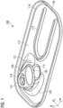
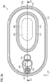
- Fig. 1 shows an end 100 for a container.
- the end 100 comprises central panel 112 and a tab 140.
- the tab 140 is attached to the end 100, especially to the central panel 112, via a rivet 116 and the tab 140 comprises a front portion 141 and a rear portion 142.
- the central panel 112 of the end 100 defines an x-y-plane.
- a z-direction is perpendicular to the x-y-plane.
- a stabilizing bead 113 is formed in the end 100, preferably in the central panel 112, and extends in the positive z-direction from the x-y-plane of the central panel 112.
- the stabilizing bead 113 is substantially c-shaped and not fully surrounds a portion of the central panel 112. Beads such as stabilizing bead 113 are formed to enhance mechanical stability of an end.
- the end 100 comprises a depression 114 that is formed in the end 100, preferably in the central panel 112, and extends in the negative z-direction from the x-y-plane.
- the depression 114 has a basic circular shape and is positioned such that a portion of the tab 140, i.e. the rear portion 142 of the tab 140, overlaps the depression 114.
- the depression allows a consumer to reach the rear portion 142 in a more convenient manner, when the consumer intends to lift the rear portion 142 of the tab 140 in order to open the end 100.
- a first bulge 120 and a second bulge 121 are formed in the end 100, preferably in the central panel 112 of the end 100.
- the bulges 120, 121 extend from the x-y-plane in the positive z-direction.
- the first bulge 120 is located close to a first side of the tab 140 that extends from the front portion 141 to the rear portion 142.
- the second bulge 121 is located close to a second side of the tab 140 that extends from the front portion 141 to the rear portion 142.
- the first side of the tab 140 and the second side of the tab 140 are opposite sides.
- the bulges 120, 121 are provided to prevent a rotation of the tab 140 about the rivet 116 in a plane parallel to the x-y-plane. Such a rotation of the tab 140 prior to lifting the rear portion 142 of the tab 140 might cause the tab 140 to break since the front portion 141 of the tab 140 can attack the central panel 112 at a position that is too far away from the score line 118 as mechanically weakened portion of the end 100, preferably of the central panel 112.
- the score line 118 as mechanically weakened portion is located in the end 100, preferably in the central panel 112, close to the outer edge of the end 100.
- the score line 118 surrounds a portion of the end 100, specifically the central panel 112.
- the tab 140 is positioned and shaped such that the front portion 141 of the tab 140 contacts (a portion of the end close to) the score line 118 in order to break a portion of the end 100, e.g. the central panel 112, when the tab 140 is pivoted about the rivet 116 by lifting the rear portion 142 of the tab 140.
- By pulling the tab 140 away from the end 100 a large portion of the central panel 112 that is surrounded by the score line 118 is removed from the end 100 and the end 100 is open.
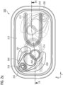
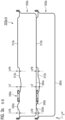
- Fig. 2a shows a first end 200 in a top view, wherein a further end 200 is indicated below the first end 200 that is rotated by 180 ° in a x-y-plane as will be discussed in more detail below.
- the end 200 may be equal to the end 100.
- the end 200 comprises a central panel 212 that defines an x-y-plane.
- a stabilizing bead 213 is formed and the stabilizing bead 213 extends in a positive z-direction, wherein the z-direction is perpendicular to the x-y-plane.
- a depression 214 is formed, preferably in the central panel 212, and the depression 214 extends in the negative z-direction.
- End 200 comprises a tab 240 with a front portion 241 and a rear portion 242.
- the tab 240 is attached to the end 200, e.g. to the central panel 212, via a rivet 216.
- the depression 214 is partially overlapped by a portion of the tab 240, specifically by the rear portion 242 of the tab 240.
- the front portion 241 of the tab 240 may break a score line 218 that is located close to the outer edge of the end 200, when the tab 240 is pivoted about the rivet 216 by lifting the rear portion 242 of the tab 240.
- a first bulge 220 and a second bulge 221 are formed in the end 200, preferably in the central plane 212.
- the bulges 220, 221 extend in the positive z-direction from the x-y-plane.
- a curl 230 is located at the outer edge of the end 200.
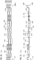
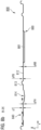
- FIG. 2a a cross section A-A is indicated that is shown in Fig. 2b and 2c .
- Fig. 2b depicts a stack of ends 200a-e comprising several ends 200 as ends 200a, 200b, 200c, 200d and 200e.
- the ends 200a through 200e are same ends 200.
- the ends 200a-e are each rotated by 180 °in the x-y-plane relative to the next end 200 in the stack 200a-e.
- end 200a has the same orientation as end 200 as shown in Fig. 2a .
- end 200b is rotated by 180 ° in the x-y-plane and positioned below end 200a.
- end 200c is rotated by 180 ° in the x-y-plane and positioned below end 200b.
- Other ends of the stack 200a-e are positioned similarly.
- Each of the ends 200a through 200e comprises a tab 240, wherein the tab 240 of end 200a is denoted as tab 240a and so on.
- Each of the ends 200a through 200e further comprises a central panel 212, a stabilizing bead 213, at least one bulge 220 and a depression 214.
- the depression 214a of the first end 200a in the stack of ends 200a-e may contact the central panel 212b of the second end 200b in the stack of ends 200a-e.
- the tab 240b of the second end 200b may contact the (lower side of the) central panel 212a of the first end 200a.
- the stabilizing bead 213b of the second end 200b may contact the (lower side of the) central panel 212a of the first end 200a.
- the at least one bulge 220b may contact the (lower side of the) central panel 212a of the first end 200a.
- the tab 240b of the second end 200b contacts the (lower side of the) central panel 212a of the first end 200a and the stabilizing bead 213b of the second end 200b contacts the (lower side of the) central panel 212a of the first end 200a.
- the central planes 212a-e of the stack of ends 200a-e are parallel and the stack of ends 200a-e shows a high stability.
- a stack of ends 200a and 200b only is depicted.
- the at least one bulge 220a, 220b of ends 200a, 200b may have an extension sTB in the positive z-direction between 0.4 mm and 2.5 mm, preferably between 0.7 mm and 2.0 mm, more preferably between 1.0 mm and 1.5 mm.
- the at least one bulge 220a, 220b has an extension sTB of about 1.2 mm in the positive z-direction.
- the at least one bulge 220a, 220b of ends 200a, 200b may have an extension sTB lower or equal to an extension sT in the positive z-direction of the tab 240a, 240b.
- the tab 240a, 240b of ends 200a, 200b may have a extension sT in the positive z-direction between 1.4 mm and 2.5 mm, preferably between 1.7 mm and 2.2 mm, more preferably between 1.8 mm and 2.0 mm. Specifically, the tab 240a, 240b has an extension sT of about 1.95 mm in the positive z-direction.
- the depression 214a, 214b of ends 200a, 200b may have an extension sFH from the respective central panel 212a, 212b in the negative z-direction between 0.5 mm and 4.0 mm, preferably between 1.0 mm and 2.5 mm, more preferably between 1.2 mm and 1.5 mm. Specifically, the depression 214a, 214b has an extension sFH of about 1.25 mm in the negative z-direction.
- the stabilizing bead 213a, 213b of ends 200a, 200b may haven extension sPB in the positive z-direction between 0.4 mm and 2.5 mm, preferably between 0.5 mm and 1.5 mm, more preferably between 0.6 mm and 1.0 mm. Specifically, the stabilizing bead 213a, 213b has an extension sPB of about 0.8 mm in the positive z-direction.
- the depression 214a, 214b of an end 200a, 200b may be spaced from the stabilizing bead 213a, 213b of another end 200b, 200a, specifically when the ends 200a, 200b are stacked while the ends 200a, 200b are rotated relative to another by 180 ° in the x-y-plane.
- the depression 214a, 214b of an end 200a, 200b is at least partially surrounded by the stabilizing bead 213a, 213b of another end 200b, 200a (in a plane parallel to the x-y-plane), specifically when the ends 200a, 200b are stacked while the ends 200a, 200b are rotated relative to another by 180 ° in the x-y-plane.
- Fig. 3a shows a container 350 comprising an end 300.
- the end 300 is the same as the ends 100, 200.
- the end 300 comprises a stabilizing bead 313, that is formed in the end 300, e.g. in a central panel 312 of the end 300, and extends in a positive z-direction.
- the end 300 comprises a tab 340 having a front portion 341 and a rear portion 342.
- the tab 340 is attached to the end 300, specifically to the central panel 312 of the end 300, via a rivet 316.
- Two bulges 320, 321 are formed in the end 300, preferably in the central panel 312 of the end 300, and extend in the positive z-direction from the x-y-plane.
- the bulges 320, 321 are positioned close to the tab 340 as described above with reference to ends 100, 200.
- a depression 314 is formed in the end 300, specifically in the central panel 312, and extends in the negative z-direction from the x-y-plane of the central panel 312 as also described above with reference to ends 100, 200.
- a score line 318 surrounds a large portion of the central panel 312 and is positioned and functions as described above with reference to ends 100, 200.
- a curl 330 is seamed to a container body 360a,b (see Fig. 3b ) for attaching the end 300 to the container body 360a, b and to form a closed container 350.
- FIG. 3a The cross section B-B indicated in Fig. 3a is shown in Fig. 3b and 3c .
- Fig. 3b depicts a stack of containers 350a, 350b wherein each container 350a, 350b is equal to container 350.
- Each container 350a, 350b comprises an end 300a, 300b having a stabilizing bead 313a, 313b, a central panel 312a, 312b, a depression 314a, 314b, a tab 340a, 340b and at least one bulge 320a, 320b.
- the end 300a, 300b is attached to a container body 360a, 360b that comprises a lower surface 385a, 385b.
- the containers 350a, 350b are stacked and the central panels 312a, 312b of the respective ends 300a, 300b are substantially parallel ( ⁇ 2.0 °).
- the lower surfaces 385a, 385b of the containers 350a, 350b may be substantially parallel ( ⁇ 2.0 °).
- the stabilizing bead 312b of an end 300b of a container 350b may contact the lower surface 385a of another container 350a, when the containers 350a, 350b are stacked.
- the tab 340b of an end 300b of a container 350b may contact the lower surface 385a of another container 350a, when the containers 350a, 350b are stacked.
- the at least one bulge 320b of an end 300b of a container 350b may contact the lower surface 385a of another container 350a, when the containers 350a, 350b are stacked.
- the extension sT of the tab 340a, 340b of ends 300a, 300b of containers 350a, 350b in the positive z-direction may be between 1.4 mm and 2.5 mm, preferably between 1.7 mm and 2.2 mm, more preferably between 1.8 mm and 2.0 mm.
- the tab 340a, 340b has an extension sT of about 1.95 mm in the positive z-direction.
- the at least one bulge 320a, 320b of ends 300a, 300b of containers 350a, 350b may have an extension sTB in the positive z-direction between 0.4 mm and 2.5 mm, preferably between 0.7 mm and 2.0 mm, more preferably between 1.0 mm and 1.5 mm.
- the at least one bulge 320a, 320b has an extension sTB of about 1.2 mm in the positive z-direction.
- the at least one bulge 320a, 320b of ends 300a, 300b of containers 350a, 350b may have an extension sTB lower or equal to the extension sT in the positive z-direction of the tab 340a, 340b.
- the extension sPB of the stabilizing bead 313a, 313b of ends 300a, 300b of containers 350a, 350b in the positive z-direction may be between 0.4 mm and 2.5 mm, preferably between 0.5 mm and 1.5 mm, more preferably between 0.6 mm and 1.0 mm.
- the stabilizing bead 313a, 313b has an extension sPB of about 0.8 mm in the positive z-direction.
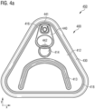
- Fig. 4a depicts a container 450 that comprises an end 400 and a container body (not shown in Fig. 4a ) analogous to e.g. container body 360a comprised by container 350a.
- a tab 440 comprising a front portion 441 and a rear portion 442 is attached to the end 400, specifically to the central panel 412, via a rivet 416.
- the rear portion 442 of the tab 440 partially covers the depression 414 such that a consumer may reach the rear portion 442 of the tab 440 by moving a portion of the finger into the depression 414 and at least partially below the rear portion 442 of the tab 440.
- the depression 414 is not (fully) surrounded by the stabilizing bead 413.
- a score line 418 is formed in an outer portion of the end 400, e.g. in the central plane 412, and surrounds a (large) portion of the end 400, e.g. the central plane 412.
- the end 400 is seamed to the container body via curl 430 of the end 400.
- the end 400 has a basic triangular shape in the x-y-plane.
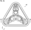
- Fig. 4b shows the end 400 in a top view. Further ends 400 are indicated below the shown end 400, wherein the ends 400 below the shown end 400 are rotated by 120 ° in the x-y-plane relative to the next end 400 as will be more detailed described with reference to Fig. 4c .
- a cross section C-C is indicated in Fig. 4b .
- a stack of ends 400a-e is shown in the cross sectional view C-C indicated in Fig. 4b .
- Five ends 400 as ends 400a, 400b, 400c, 400d, and 400e are stacked.
- the end 400a has the same orientation in the x-y-plane as the end 400 shown in Fig. 4b .
- Each end 400a-e is rotated by 120 ° in the x-y-plane relative to the preceding end 400a-e in the stack.
- end 400b is rotated by 120 ° in the x-y-plane relative to the end 400a
- end 400c is rotated by 120 ° in the x-y-plane relative to the end 400b in the x-y-plane.
- Other ends 400d-e are orientated in the x-y-plane analogously.
- end 400c is rotated by 240 ° in the x-y-plane relative to the end 400a and e.g. end 400d has the same orientation in the x-y-plane as end 400a.
- Each of the ends 400a-e comprises a central panel 412a-e, a stabilizing bead 413a-e, a depression 414a-e and a tab 440a-e.
- the central panels 412a-e of the stack of ends 400a-e are (substantially) parallel. Thereby, the stack of ends 400a-e shows an enhanced stability.
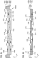
- Fig. 4d depicts three stacked ends 400a-c, wherein each of the ends 400a-c is an end 400 as described above.
- the tab 440a-c of the ends 400a-c may have an extension sT in the positive z-direction between 1.4 mm and 2.5 mm, preferably between 1.7 mm and 2.2 mm, more preferably between 1.8 mm and 2.0 mm.
- the tab 240a, 240b has an extension sT of about 1.95 mm in the positive z-direction.
- the stabilizing bead 413a-c of ends 400a-c may have an extension sPB in the positive z-direction between 0.4 mm and 2.5 mm, preferably between 0.5 mm and 1.5 mm, more preferably between 0.6 mm and 1.0 mm. Specifically, the stabilizing bead 413a-c has an extension sPB of about 0.8 mm in the positive z-direction.
- the depression 414a-c of ends 400a-c may have an extension sFH in the negative z-direction between 0.5 mm and 4.0 mm, preferably between 1.0 mm and 2.5 mm, more preferably between 1.2 mm and 1.5 mm. Specifically, the depression 414a-c has an extension sFH of about 1.25 mm in the negative z-direction.
- the stabilizing bead 413b of the end 400b may contact the end 400a, specifically the central panel 412a.
- the tab 440b of the end 400b may contact the end 400a, specifically the central panel 412a.
- the tab 440c of the end 400c may contact the end 400b, preferably the central panel 412b.
- the tab 440c of the End 400c may contact the end 400b, e.g. the central panel 412b.
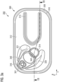
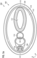
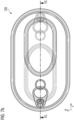
- Fig. 5a depicts a container 550 comprising an end 500 and a container body (not shown in Fig. 5a ).
- the end 500 is seamed to the container body for closing the container 550 via a curl 530 of the end 500.
- the end 500 comprises a central panel 512 that defines an x-y-plane.
- a stabilizing bead 513 is formed and the stabilizing bead 513 extends in a positive z-direction, wherein the z-direction is perpendicular to the x-y-plane.
- a depression 514 is formed in the end 500, preferably in the central panel 512, that extends in the negative z-direction.
- End 500 comprises a tab 540 with a front portion 541 and a rear portion 542.
- the tab 540 is attached to the end 500, specifically to the central plane 512, via a rivet 516.
- the Depression 514 is partially overlapped by a portion of the tab 540, specifically by the rear portion 542 of the tab 540.
- the front portion 541 of the tab 540 may break a score line 518 that is located close to the outer edge of the end 500, when the tab 540 is pivoted about the rivet 516 by lifting the rear portion 542 of the tab 540.
- the stabilizing bead 513 (fully) surrounds a portion of the central panel 512.
- the depression 514 may be positioned outside the surrounded portion of the central panel 512.
- the depression 514 may not be surrounded by the stabilizing bead 513.
- the stabilizing bead 513 may have a basic oval shape.
- the end 500 may have a basic oval shape.
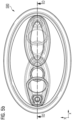
- Fig. 5b shows the end 500 in a top view, wherein a further end 500 is indicated below the end 500. Further, a cross section D-D is indicated in Fig. 5b .
- Fig. 5c depicts a stack of ends 500a-e comprising several ends 500 as ends 500a, 500b, 500c, 500d and 500e.
- the ends 500a-e are each rotated by 180 °in the x-y-plane relative to the next end 500 in the stack 500a-e.
- end 500a has the same orientation as end 500 as shown in Fig. 5b .
- end 500b is rotated by 180 ° in the x-y-plane and positioned below end 500a.
- Other ends of the stack 500a-e are positioned and orientated similarly.
- Each of the ends 500a-e comprises a tab 540a-e.
- Each of the ends 500a-e further comprises a central panel 512a-e, a stabilizing bead 513a-e and a depression 514a-e.
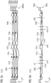
- Fig. 5d a stack of ends 500a and 500b is depicted.
- the tab 540a-b of ends 500a-b may have an extension sT in the positive z-direction between 1.4 mm and 2.5 mm, preferably between 1.7 mm and 2.2 mm, more preferably between 1.8 mm and 2.0 mm. Specifically, the tab 540a-b has an extension sT of about 1.95 mm in the positive z-direction.
- the depression 514a-b of ends 500a-b may have an extension sFH in the negative z-direction between 0.5 mm and 4.0 mm, preferably between 1.0 mm and 2.5 mm, more preferably between 1.2 mm and 1.5 mm. Specifically, the depression 514a-b has an extension sFH of about 1.25 mm in the negative z-direction.
- the stabilizing bead 513a-b of ends 500a-b may have an extension sPB in the positive z-direction between 0.4 mm and 2.5 mm, preferably between 0.5 mm and 1.5 mm, more preferably between 0.6 mm and 1.0 mm. Specifically, the stabilizing bead 513a-b has an extension sPB of about 0.8 mm in the positive z-direction.
- the depression 514a of the first end 500a in the stack of ends 500a-b may contact the second end 500b, preferably the central panel 512b, in the stack of ends 500a-b.
- the tab 540b of the second end 500b may contact the first end 500a, preferably the central panel 512a.
- the stabilizing bead 513b of the second end 500b may contact the first end 500a, specifically the central panel 512a.
- the tab 540b of the second end 500b contacts the first end 500a, e.g. the central panel 512a of the first end 500a, and the stabilizing bead 513b of the second end 500b contacts the first end 500a, e.g. the central panel 512a.
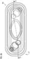
- Fig. 6a shows a stack of two containers 650a-b, wherein each of the containers 650a-b comprises an end 600a-b and a container body 660a-b (also see Fig. 6c and 6d ). In Fig. 6a only the end 600a is visible due to the perspective view on the stack of containers 650a-b. Further, a cross section E-E is indicated in Fig. 6a that is shown in Fig. 6d .
- the end 600a comprises a stabilizing bead 613a, that is formed in the end 600a, preferably in a central panel 612a of the end 600a, and extends in a positive z-direction from a x-y-plane defined by the central panel 612a.
- the end 600a comprises a tab 640a having a front portion 641a and a rear portion 642a.
- the tab 640a is attached to the end 600a, specifically to the central panel 612a of the end 600a, via a rivet 616a.
- a depression 614a is formed in the end 600a, preferably in the central panel 612a, and extends in the negative z-direction from the x-y-plane of the central panel 612a.
- a score line 618a surrounds a (large) portion of the end 600a, preferably the central panel 612a, as a mechanically weakened portion described above.
- a curl 630a is seamed to the container body 660a (see Fig. 6d ) for attaching the end 600a to the container body 660a and to form a closed container 650a.
- the end 600a has a basic oblong rectangular shape. Two sides of the basic rectangular shape are longer, preferably at least two or three times longer, than the other two sides of the basic rectangular shape.
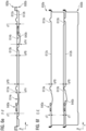
- Fig. 6b shows an end 600, e.g. end 650. Further ends 600 are indicated below end 600. Additionally, a cross section F-F is indicated in Fig. 6b that is shown in Fig. 6c .
- Fig. 6c depicts a stack of ends 600a-e comprising ends 600a, 600b, 600c, 600d and 600e.
- ends 600a-e are each rotated by 180 °in the x-y-plane relative to the next end 600 in the stack 600a-e.
- end 600a has the same orientation as end 600 as shown in Fig. 6b .
- end 600b is rotated by 180 ° in the x-y-plane and positioned below end 600a.
- Other ends of the stack 600a-e are positioned and orientated similarly.
- Each of the ends 600a-e comprises a tab 640a-e.
- Each of the ends 600a-e further comprises a central panel 612a-e, a stabilizing bead 613a-e and a depression 614a-e.
- Fig. 6d shows a stack of containers 650a-b as indicated in Fig. 6a .
- Each container 650a-b comprises an end 600a-b and a container body 660a-b.
- Each end 600a-b comprises a stabilizing bead 613a-b, a central panel 612a-b, a depression 614a-b and a tab 640a-b.
- the container bodies 660a-b comprise a lower surface 685a-b.
- the containers 650a-b are stacked and the central panels 612a-b of the respective ends 600a-b are substantially parallel ( ⁇ 2.0 °).
- the tab 640b of end 600b may contact the lower surface 685a of end 600a.
- the stabilizing bead 613b of end 600b may contact the lower surface 685a of end 600a.
- Fig. 6e a stack of ends 600a and 600b is depicted.
- the ends 600a and 600b as shown in Fig. 6e and described with reference to Fig. 6e are not attached to a container body.
- the tab 640a-b of ends 600a-b may have an extension sT in the positive z-direction between 1.4 mm and 2.5 mm, preferably between 1.7 mm and 2.2 mm, more preferably between 1.8 mm and 2.0 mm. Specifically, the tab 640a-b has an extension sT of about 1.95 mm in the positive z-direction.
- the depression 614a-b of ends 600a-b may have an extension sFH in the negative z-direction between 0.5 mm and 4.0 mm, preferably between 1.0 mm and 2.5 mm, more preferably between 1.2 mm and 1.5 mm. Specifically, the depression 614a-b has an extension sFH of about 1.25 mm in the negative z-direction.
- the stabilizing bead 613a-b of ends 600a-b may have an extension sPB in the positive z-direction between 0.4 mm and 2.5 mm, preferably between 0.5 mm and 1.5 mm, more preferably between 0.6 mm and 1.0 mm. Specifically, the stabilizing bead 613a-b has an extension sPB of about 0.8 mm in the positive z-direction.
- the central panels 612a-b of ends 600a-b are (substantially) parallel. Thus, a stack of ends 600a, 600b with a high stability is provided.
- a stack of containers 650a-b is shown, wherein each of the containers 650a-b comprises an end 600a-b as described above.
- the central panels 612a-b of the ends 600a-b of the containers 650a-b are (substantially) parallel.
- the lower surfaces 685a-b of containers 650a-b may be (substantially) parallel.
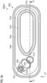
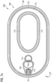
- Fig. 7a depicts a container 750 comprising an end 700 and a container body.
- the container body is not shown in Fig. 7a .
- the end 700 is seamed to the container body for closing the container 750 via a curl 730 of the end 700.
- the end 700 comprises a central panel 712 that defines an x-y-plane.
- a stabilizing bead 713 is formed and the stabilizing bead 713 extends in a positive z-direction, wherein the z-direction is perpendicular to the x-y-plane.
- a depression 714 is formed in the end 700, e.g. in the central panel 712, that extends in the negative z-direction.
- End 700 comprises a tab 740 with a front portion 741 and a rear portion 742.
- the tab 740 is attached to the end 700, e.g. to the central panel 712, via a rivet 716.
- the Depression 714 is partially overlapped by a portion of the tab 740, specifically by the rear portion 742 of the tab 740.
- the front portion 741 of the tab 740 may break a score line 718 as described above.
- the stabilizing bead 713 (fully) surrounds a portion of the central panel 712.
- the depression 714 may be positioned outside the surrounded portion of the central panel 712.
- the depression 714 may not be surrounded by the stabilizing bead 713.
- the stabilizing bead 713 may have a basic oval shape with two elongated sides that may be parallel over a distance of at least 10 mm.
- the end 700 may have a basic oval shape with two elongated sides that may be parallel over a distance of at least 10 mm.
- Fig. 7b shows the end 700 in a top view. A further end 700 is indicated below the end 700. A cross section G-G is indicated in Fig. 7b .
- Fig. 7c depicts a stack of ends 700a-e. Each of the ends 700a-e may be an end 700 as described above.
- ends 700a-e are each rotated by 180 °in the x-y-plane relative to the next end 700 in the stack 700a-e.
- end 700a has the same orientation as end 700 as shown in Fig. 7b .
- End 700b is rotated by 180 ° in the x-y-plane relative to end 700a and positioned below end 700a.
- Other ends of the stack 700a-e are positioned and orientated similarly.
- Each of the ends 700a-e comprises a tab 740a-e, a central panel 712a-e, a stabilizing bead 713a-e and a depression 714a-e.
- the tab 740a-b of ends 700a-b may have an extension sT in the positive z-direction between 1.4 mm and 2.5 mm, preferably between 1.7 mm and 2.2 mm, more preferably between 1.8 mm and 2.0 mm. Specifically, the tab 740a-b has an extension sT of about 1.95 mm in the positive z-direction.
- the depression 714a-b of ends 700a-b may have an extension sFH in the negative z-direction between 0.5 mm and 4.0 mm, preferably between 1.0 mm and 2.5 mm, more preferably between 1.2 mm and 1.5 mm. Specifically, the depression 714a-b has an extension sFH of about 1.25 mm in the negative z-direction.
- the stabilizing bead 713a-b of ends 700a-b may have an extension sPB in the positive z-direction between 0.4 mm and 2.5 mm, preferably between 0.5 mm and 1.5 mm, more preferably between 0.6 mm and 1.0 mm. Specifically, the stabilizing bead 713a-b has an extension sPB of about 0.8 mm in the positive z-direction.
- the depression 714a of the first end 700a in the stack of ends 700a-b may contact the end 700b, specifically the central panel 712b, in the stack of ends 700a-b.
- the tab 740b of the second end 700b may contact the first end 700a, e.g. the central panel 712a.
- the stabilizing bead 713b of the second end 700b may contact the first end 700a, preferably the central panel 712a.
- the tab 740b of the second end 700b contacts the first end 700a, preferably the central panel 712a, and the stabilizing bead 713b of the second end 700b contacts the first end 700a, specifically the central panel 712a.
- Fig. 8a shows an end 800 that can be similar to any of the ends 100, 200, 300, 400, 500, 600, 700 and comprises a stabilizing bead 813.
- the end 800 comprises a central panel 812 that defines an x-y-plane, wherein a z-direction is perpendicular to the x-y-plane.
- the stabilizing bead 813 is formed in the end 800, e.g. in the central panel 812 of the end 800.
- the stabilizing bead 813 extends in the positive z-direction.
- a depression 814 is formed in the end 800, specifically in the central panel of the end 800.
- the depression 814 is positioned such that a rear portion 842 of a tab 840, attached to the end 800, e.g. to the central panel 812, via a rivet 816, covers the depression 814 at least partially.
- a front portion 841 of the tab 840 may break a score line 818 in the end 800, preferably in the central panel 812, when a consumer uses the tab as described above in order to remove a (large) portion of the end 800, e.g. of the central panel 812, surrounded by the score line 818.
- the end 800 may be attached to a container body (not shown in Fig. 8a ) via a curl 830.
- a bead 880 is formed that extends in the negative z-direction.
- the bead 880 may be formed such that a surface 881, preferably with an area of at least 100 mm 2 , is formed.
- the surface 881 may be substantially parallel to the central panel 812.
- the surface 881 may extend in the negative z-direction.
- the bead 880 may be partially surrounded by the stabilizing bead 813.
- the bead 880 may be fully surrounded by the stabilizing bead 813.
- the bead 880 may not be surrounded by the stabilizing bead 813.
- the bead 880 and/or the surface 881 may extend sNB between 0.5 mm and 4.0 mm, preferably between 1.0 mm and 2.5 mm, more preferably between 1.2 mm and 1.5 mm, in the negative z-direction that is perpendicular to the x-y-plane of the central panel.
- the bead 880 and the depression 814 may be positioned and shaped such that the x-y-plane of the central panel of the end is parallel to a flat surface ⁇ 2.0 °, preferably ⁇ 1.5 °, more preferably ⁇ 1.0 °, most preferred ⁇ 0.5 °, when the end is positioned on the flat surface.
- the bead 880 and the depression 814 may be positioned and shaped sFH,sNB such that the x-y-plane of the central panel of the end is parallel to a flat surface ⁇ 2.0 °, preferably ⁇ 1.5 °, more preferably ⁇ 1.0 °, most preferred ⁇ 0.5 °, when the bead and/or the depression contacts the flat surface.
- the extension sNB of the bead 880 may be equal to the extension of the depression 814 in the negative z-direction ⁇ 1.5 mm, preferably ⁇ 1.0 mm, more preferably ⁇ 0.5 mm, most preferably ⁇ 0.2 mm. It is especially preferred that the extension sNB of the bead is substantially equal to the extension of the depression in the negative z-direction.
- the tab 840 of end 800 may have an extension sT in the positive z-direction between 1.4 mm and 2.5 mm, preferably between 1.7 mm and 2.2 mm, more preferably between 1.8 mm and 2.0 mm. Specifically, the tab 800 has an extension sT of about 1.95 mm in the positive z-direction.
- the depression 814 of end 800 may have an extension sFH in the negative z-direction between 0.5 mm and 4.0 mm, preferably between 1.0 mm and 2.5 mm, more preferably between 1.2 mm and 1.5 mm. Specifically, the depression 814 has an extension sFH of about 1.25 mm in the negative z-direction.
- the stabilizing bead 813 of end 800 may have an extension sPB in the positive z-direction between 0.4 mm and 2.5 mm, preferably between 0.5 mm and 1.5 mm, more preferably between 0.6 mm and 1.0 mm. Specifically, the stabilizing bead 813 has an extension sPB of about 0.8 mm in the positive z-direction.
- FIG. 8c An alternative embodiment of an end 800a comprising a bead 880a',880a" that extends in the negative z-direction is shown in Fig. 8c .
- the bead 880a',880a" comprises a first portion 880a' and a second portion 880a".
- the first and second portions of the bead 880a',880a" are located in the end 800a, preferably in the central panel 812a, such that the stabilizing bead 813a does not surround a portion of the bead 880a',880a".
- Each of the portions 880a',880a” may have an elongated shape in the x-y-plane.
- the portions 880a',880a” may extend in the x-y-plane from a portion of the tab 840a to a portion of the stabilizing bead 813a.
- Preferably the stabilizing bead 813a is at least partially surrounded by the portions 880a',880a" of the bead.
- Fig. 8d shows another alternative of an end 800b comprising a bead 880b',880b" that extends in the negative z-direction.
- the bead 880b',880b" comprises a first portion 880b' and a second portion 880b", wherein each of the portions 880b',880b" comprises more than one, preferably at least three, independent beads that extend in the negative z-direction.
- the independent beads of the portions 880b',880b" may have a substantially circular shape in the x-y-plane, an oval shape in the x-y-plane and/or an elongated shape in the x-y-plane.
- the portions 880b',880b" may be located in the end 800b, e.g. in the central panel 812b, such that the stabilizing bead 813b does not surround a portion of the bead 880b',880b".
- the stabilizing bead 813b may be at least partially surrounded by the portions 880b',880b" of the bead.
- the beads 880, 880a', 880a", 880b', 880b" are described herein with reference to Fig. 8a to 8d
- the second beads 880, 880a', 880a", 880b', 880b" as described may be comprised by any one of the ends 100, 200, 300, 400, 500, 600, 700 described herein.
- Each of the herein described ends 100, 200, 300, 400, 500, 600, 700, 800 may comprise at least one bulge 120,121; 220,221 as described with reference to Fig. 1 , 2a to 2c and 3a to 3c .
Landscapes
- Engineering & Computer Science (AREA)
- Mechanical Engineering (AREA)
- Rigid Containers With Two Or More Constituent Elements (AREA)
- Stackable Containers (AREA)
Claims (15)
- Ende (Deckel) für einen Behälter, wobei der Deckel (800) umfasst:(a) eine zentrale Platte (812), die eine x-y-Ebene definiert, wobei eine z-Richtung senkrecht zur x-y-Ebene verläuft;(b) eine Lasche (Tab; 840), die an dem Ende (800) angebracht ist, wobei die Lasche (840) einen vorderen Abschnitt (841) und einen hinteren Abschnitt (842) aufweist und wobei sich die Lasche (840) in einer positiven z-Richtung erstreckt;(c) eine Vertiefung (814), die in dem Deckel (800) ausgebildet ist und wobei sich die Vertiefung (814) in einer negativen z-Richtung erstreckt, wobei die Vertiefung (814) so geformt und positioniert ist, dass ein menschlicher Finger zumindest teilweise unter den hinteren Abschnitt (842) der Lasche (840) reichen kann;(d) mindestens einen ersten Wulst (Sicke; 880), der in dem Deckel (800) geformt ist und wobei der erste Wulst (880) sich in der negativen z-Richtung erstreckt;(e) wobei die Vertiefung (814) und der ersten Wulst (880) so geformt und positioniert sind, dass, wenn der Deckel (800) auf einer flachen Oberfläche positioniert ist, während die Vertiefung (814) und der erste Wulst (880) die flache Oberfläche berühren, die durch die zentrale Platte (812) definierte x-y-Ebene parallel, ±2,0°, zu der flachen Oberfläche, verläuft;dadurch gekennzeichnet, dass(f1) der Deckel einen stabilisierenden Wulst oder Sicke (813) umfasst, in dem Deckel ausgeformt, wobei sich der stabilisierende Wulst/Sicke (813) in der positiven z-Richtung erstreckt;(f2) und die Ausdehnung (sT) der Lasche (840) in positiver z-Richtung gleich, ±0,3mm, der Ausdehnung (sPB) des Stabilisierungswulstes (813) in positiver z-Richtung ist.
- Deckel nach Anspruch 1, wobei die Ausdehnung (sNB) des ersten Wulstes (880) in der negativen z-Richtung -gleich der Ausdehnung (sFH) der Vertiefung (814) in der negativen z-Richtung -±1,5 mm, vorzugsweise ±1,0 mm, noch bevorzugter ±0,5 mm, am meisten bevorzugt ±0,2 mm -ist.
- Deckel nach einem der vorhergehenden Ansprüche, wobei die Ausdehnung (sT) der Lasche (840) in positiver z-Richtung gleich der Ausdehnung (sPB) des Stabilisierungswulstes (813) ist.
- Deckel nach einem der vorhergehenden Ansprüche, wobei die Ausdehnung (sFH) der Vertiefung (814) in negativer z-Richtung gleich, ±2,0 mm, der Ausdehnung (sPB) des Stabilisierungswulstes (813) in positiver z-Richtung ist, vorzugsweise ±1,2mm, besonders bevorzugt ±0,8mm.
- Deckel nach Anspruch 4, wobei die Ausdehnung (sFH) der Vertiefung (814) in negativer z-Richtung gleich der Ausdehnung (sT) der Lasche (840) in positiver z-Richtung ist, ±1,0mm, vorzugsweise ±0,5mm, besonders bevorzugt ±0,2mm.
- Deckel nach einem der vorangehenden Ansprüche, umfassend mindestens eine Ausbuchtung (120), wobei die Ausbuchtung (120) im Deckel (800) geformt ist, sich in positiver z-Richtung erstreckt und in der Nähe einer Außenseite der Lasche (840) angeordnet ist.
- Deckel nach Anspruch 6, wobei die Ausdehnung der Ausbuchtung (120) geringer ist als die Ausdehnung (sT) der Lasche in positiver z-Richtung.
- Deckel nach Anspruch 6, wobei die Ausdehnung (sTB) der Ausbuchtung (120) in positiver z-Richtung -gleich der Ausdehnung (sT) der Lasche (840) in positiver z-Richtung -±2,0 mm, vorzugsweise ±1,5 mm, noch bevorzugter ±1,0 mm -ist,
und/oderdie Ausdehnung (sTB) des Wulstes (120) in positiver z-Richtung -gleich der Ausdehnung (sPB) des Stabilisierungswulstes (813) in positiver z-Richtung -±2,0 mm, vorzugsweise ±1,2 mm, besonders bevorzugt ±0,6 mm -ist,
und/oderdie Ausdehnung (sTB) der Ausbuchtung (120) in der positiven z-Richtung -gleich der Ausdehnung (sFH) der Vertiefung (814) in der negativen z-Richtung -±2,0 mm, vorzugsweise ±1,0 mm, noch bevorzugter ±0,5 mm, am meisten bevorzugt ±0,2 mm -ist. - Deckel nach einem der vorhergehenden Ansprüche, wobei die Ausdehnung (sNB) des ersten Wulstes (880) in der negativen z-Richtung zwischen 0,5 mm und 4,0 mm, vorzugsweise zwischen 1,0 mm und 2,5 mm, besonders bevorzugt zwischen 1,2 mm und 1,5 mm liegt.
- Deckel nach einem der vorhergehenden Ansprüche, wobei das Ende (800) aus Metall, vorzugsweise Stahl oder Aluminium, besteht oder aus Metall, vorzugsweise Stahl oder Aluminium, hergestellt ist.
- Deckel nach einem der vorhergehenden Ansprüche, wobei die Vertiefung (814) in der x-y-Ebene nicht von dem Stabilisierungswulst (813) umgeben ist.
- Stapel aus mindestens zwei Deckel (800; 200a, 200b ...) nach einem der vorhergehenden Ansprüche.
- Behälter, umfassend einen Deckel (800) nach einem der Ansprüche 1 bis 11.
- Behälter nach Anspruch 13, der Lebensmittel enthält.
- Stapel aus mindestens zwei Behältern (350a, 350b ...) nach Anspruch 13 oder 14.
Applications Claiming Priority (3)
| Application Number | Priority Date | Filing Date | Title |
|---|---|---|---|
| EP19172571 | 2019-05-03 | ||
| EP19177098.1A EP3733544A1 (de) | 2019-05-03 | 2019-05-28 | Endstück für einen behälter mit verbesserter transportfähigkeit und behälter mit dem endstück |
| PCT/IB2020/054102 WO2020225672A1 (en) | 2019-05-03 | 2020-04-30 | End for a container with enhanced transportability and container with the end |
Publications (2)
| Publication Number | Publication Date |
|---|---|
| EP3962824A1 EP3962824A1 (de) | 2022-03-09 |
| EP3962824B1 true EP3962824B1 (de) | 2025-01-22 |
Family
ID=66554121
Family Applications (2)
| Application Number | Title | Priority Date | Filing Date |
|---|---|---|---|
| EP19177098.1A Withdrawn EP3733544A1 (de) | 2019-05-03 | 2019-05-28 | Endstück für einen behälter mit verbesserter transportfähigkeit und behälter mit dem endstück |
| EP20730103.7A Active EP3962824B1 (de) | 2019-05-03 | 2020-04-30 | Endstück für einen behälter mit verbesserter transportfähigkeit und behälter mit dem endstück |
Family Applications Before (1)
| Application Number | Title | Priority Date | Filing Date |
|---|---|---|---|
| EP19177098.1A Withdrawn EP3733544A1 (de) | 2019-05-03 | 2019-05-28 | Endstück für einen behälter mit verbesserter transportfähigkeit und behälter mit dem endstück |
Country Status (6)
| Country | Link |
|---|---|
| EP (2) | EP3733544A1 (de) |
| ES (1) | ES3017182T3 (de) |
| HU (1) | HUE071281T2 (de) |
| PL (1) | PL3962824T3 (de) |
| PT (1) | PT3962824T (de) |
| WO (1) | WO2020225672A1 (de) |
Citations (1)
| Publication number | Priority date | Publication date | Assignee | Title |
|---|---|---|---|---|
| DE1761867C3 (de) * | 1968-07-16 | 1979-06-07 | Schmalbach-Lubeca-Gmbh, 3300 Braunschweig | Aufreißdeckel aus Blech, insbesondere für Konservendosen |
Family Cites Families (2)
| Publication number | Priority date | Publication date | Assignee | Title |
|---|---|---|---|---|
| US3478918A (en) * | 1968-08-14 | 1969-11-18 | American Can Co | Full open end closure |
| US5064087A (en) * | 1990-11-21 | 1991-11-12 | Koch Systems Incorporated | Self-opening can lid with improved contour of score |
-
2019
- 2019-05-28 EP EP19177098.1A patent/EP3733544A1/de not_active Withdrawn
-
2020
- 2020-04-30 PT PT207301037T patent/PT3962824T/pt unknown
- 2020-04-30 WO PCT/IB2020/054102 patent/WO2020225672A1/en not_active Ceased
- 2020-04-30 HU HUE20730103A patent/HUE071281T2/hu unknown
- 2020-04-30 ES ES20730103T patent/ES3017182T3/es active Active
- 2020-04-30 EP EP20730103.7A patent/EP3962824B1/de active Active
- 2020-04-30 PL PL20730103.7T patent/PL3962824T3/pl unknown
Patent Citations (1)
| Publication number | Priority date | Publication date | Assignee | Title |
|---|---|---|---|---|
| DE1761867C3 (de) * | 1968-07-16 | 1979-06-07 | Schmalbach-Lubeca-Gmbh, 3300 Braunschweig | Aufreißdeckel aus Blech, insbesondere für Konservendosen |
Also Published As
| Publication number | Publication date |
|---|---|
| PL3962824T3 (pl) | 2025-04-28 |
| HUE071281T2 (hu) | 2025-08-28 |
| ES3017182T3 (en) | 2025-05-12 |
| WO2020225672A1 (en) | 2020-11-12 |
| EP3962824A1 (de) | 2022-03-09 |
| PT3962824T (pt) | 2025-04-14 |
| EP3733544A1 (de) | 2020-11-04 |
Similar Documents
| Publication | Publication Date | Title |
|---|---|---|
| RU2287465C2 (ru) | Держатель для банок, картонная заготовка держателя для банок и способ сборки картонной заготовки | |
| US6648141B2 (en) | Packaging for containing and dispensing large quantities of wire | |
| RU2630572C2 (ru) | Язычок легкого открывания для торцевой крышки контейнера | |
| EP3962822B1 (de) | Stapelbarer behälter | |
| US7198152B2 (en) | Welding wire container with ribbed walls and mating retainer ring | |
| EP3962823B1 (de) | Stapelbares endstück für einen behälter und stapelbarer behälter mit dem endstück | |
| US20150060450A1 (en) | Container | |
| US20090039091A1 (en) | Can End With Countersink | |
| JP2010517890A (ja) | 缶、およびそのための本体ならびにパネル | |
| EP3962824B1 (de) | Endstück für einen behälter mit verbesserter transportfähigkeit und behälter mit dem endstück | |
| US8875936B2 (en) | Can end with negatively angled wall | |
| CN114040822A (zh) | 使用金属端盖密封金属容器的方法和设备 | |
| US4826037A (en) | Full open end | |
| AU2018263600B2 (en) | Easy open closure | |
| JP4978086B2 (ja) | 易開封性缶蓋 | |
| US20160101907A1 (en) | Tamper-evident tab thermoformed packaging | |
| US20260001732A1 (en) | Food can stacking device | |
| TWI899238B (zh) | 罐蓋用拉環以及罐蓋 | |
| JP5120976B2 (ja) | 楕円形状びん | |
| JPS6226352Y2 (de) | ||
| JP5927488B2 (ja) | 自動販売機の商品収納装置 | |
| JPS597236Y2 (ja) | 巻締蓋缶 | |
| KR20240171326A (ko) | 캔용기용 트레이 | |
| JP5961600B2 (ja) | 金属製オープンペール缶 |
Legal Events
| Date | Code | Title | Description |
|---|---|---|---|
| STAA | Information on the status of an ep patent application or granted ep patent |
Free format text: STATUS: UNKNOWN |
|
| STAA | Information on the status of an ep patent application or granted ep patent |
Free format text: STATUS: THE INTERNATIONAL PUBLICATION HAS BEEN MADE |
|
| PUAI | Public reference made under article 153(3) epc to a published international application that has entered the european phase |
Free format text: ORIGINAL CODE: 0009012 |
|
| STAA | Information on the status of an ep patent application or granted ep patent |
Free format text: STATUS: REQUEST FOR EXAMINATION WAS MADE |
|
| 17P | Request for examination filed |
Effective date: 20211203 |
|
| AK | Designated contracting states |
Kind code of ref document: A1 Designated state(s): AL AT BE BG CH CY CZ DE DK EE ES FI FR GB GR HR HU IE IS IT LI LT LU LV MC MK MT NL NO PL PT RO RS SE SI SK SM TR |
|
| DAV | Request for validation of the european patent (deleted) | ||
| DAX | Request for extension of the european patent (deleted) | ||
| STAA | Information on the status of an ep patent application or granted ep patent |
Free format text: STATUS: EXAMINATION IS IN PROGRESS |
|
| 17Q | First examination report despatched |
Effective date: 20221108 |
|
| GRAP | Despatch of communication of intention to grant a patent |
Free format text: ORIGINAL CODE: EPIDOSNIGR1 |
|
| STAA | Information on the status of an ep patent application or granted ep patent |
Free format text: STATUS: GRANT OF PATENT IS INTENDED |
|
| INTG | Intention to grant announced |
Effective date: 20230504 |
|
| RIN1 | Information on inventor provided before grant (corrected) |
Inventor name: SIREAU, LUCAS Inventor name: LEBOUCHER, FABRICE Inventor name: BOIDIN, PHILIPPE |
|
| GRAJ | Information related to disapproval of communication of intention to grant by the applicant or resumption of examination proceedings by the epo deleted |
Free format text: ORIGINAL CODE: EPIDOSDIGR1 |
|
| STAA | Information on the status of an ep patent application or granted ep patent |
Free format text: STATUS: EXAMINATION IS IN PROGRESS |
|
| INTC | Intention to grant announced (deleted) | ||
| GRAP | Despatch of communication of intention to grant a patent |
Free format text: ORIGINAL CODE: EPIDOSNIGR1 |
|
| STAA | Information on the status of an ep patent application or granted ep patent |
Free format text: STATUS: GRANT OF PATENT IS INTENDED |
|
| INTG | Intention to grant announced |
Effective date: 20240812 |
|
| GRAS | Grant fee paid |
Free format text: ORIGINAL CODE: EPIDOSNIGR3 |
|
| GRAA | (expected) grant |
Free format text: ORIGINAL CODE: 0009210 |
|
| STAA | Information on the status of an ep patent application or granted ep patent |
Free format text: STATUS: THE PATENT HAS BEEN GRANTED |
|
| AK | Designated contracting states |
Kind code of ref document: B1 Designated state(s): AL AT BE BG CH CY CZ DE DK EE ES FI FR GB GR HR HU IE IS IT LI LT LU LV MC MK MT NL NO PL PT RO RS SE SI SK SM TR |
|
| REG | Reference to a national code |
Ref country code: GB Ref legal event code: FG4D |
|
| REG | Reference to a national code |
Ref country code: CH Ref legal event code: EP |
|
| REG | Reference to a national code |
Ref country code: IE Ref legal event code: FG4D |
|
| REG | Reference to a national code |
Ref country code: DE Ref legal event code: R096 Ref document number: 602020045128 Country of ref document: DE |
|
| REG | Reference to a national code |
Ref country code: DE Ref legal event code: R082 Ref document number: 602020045128 Country of ref document: DE |
|
| REG | Reference to a national code |
Ref country code: PT Ref legal event code: SC4A Ref document number: 3962824 Country of ref document: PT Date of ref document: 20250414 Kind code of ref document: T Free format text: AVAILABILITY OF NATIONAL TRANSLATION Effective date: 20250409 |
|
| REG | Reference to a national code |
Ref country code: NL Ref legal event code: FP |
|
| REG | Reference to a national code |
Ref country code: ES Ref legal event code: FG2A Ref document number: 3017182 Country of ref document: ES Kind code of ref document: T3 Effective date: 20250512 |
|
| PGFP | Annual fee paid to national office [announced via postgrant information from national office to epo] |
Ref country code: NL Payment date: 20250429 Year of fee payment: 6 |
|
| PG25 | Lapsed in a contracting state [announced via postgrant information from national office to epo] |
Ref country code: RS Free format text: LAPSE BECAUSE OF FAILURE TO SUBMIT A TRANSLATION OF THE DESCRIPTION OR TO PAY THE FEE WITHIN THE PRESCRIBED TIME-LIMIT Effective date: 20250422 |
|
| PG25 | Lapsed in a contracting state [announced via postgrant information from national office to epo] |
Ref country code: FI Free format text: LAPSE BECAUSE OF FAILURE TO SUBMIT A TRANSLATION OF THE DESCRIPTION OR TO PAY THE FEE WITHIN THE PRESCRIBED TIME-LIMIT Effective date: 20250122 |
|
| PGFP | Annual fee paid to national office [announced via postgrant information from national office to epo] |
Ref country code: DE Payment date: 20250424 Year of fee payment: 6 Ref country code: PL Payment date: 20250425 Year of fee payment: 6 |
|
| PGFP | Annual fee paid to national office [announced via postgrant information from national office to epo] |
Ref country code: GB Payment date: 20250522 Year of fee payment: 6 Ref country code: ES Payment date: 20250519 Year of fee payment: 6 |
|
| REG | Reference to a national code |
Ref country code: LT Ref legal event code: MG9D |
|
| PG25 | Lapsed in a contracting state [announced via postgrant information from national office to epo] |
Ref country code: NO Free format text: LAPSE BECAUSE OF FAILURE TO SUBMIT A TRANSLATION OF THE DESCRIPTION OR TO PAY THE FEE WITHIN THE PRESCRIBED TIME-LIMIT Effective date: 20250422 Ref country code: IS Free format text: LAPSE BECAUSE OF FAILURE TO SUBMIT A TRANSLATION OF THE DESCRIPTION OR TO PAY THE FEE WITHIN THE PRESCRIBED TIME-LIMIT Effective date: 20250522 |
|
| PGFP | Annual fee paid to national office [announced via postgrant information from national office to epo] |
Ref country code: IT Payment date: 20250509 Year of fee payment: 6 |
|
| REG | Reference to a national code |
Ref country code: AT Ref legal event code: MK05 Ref document number: 1761326 Country of ref document: AT Kind code of ref document: T Effective date: 20250122 |
|
| PG25 | Lapsed in a contracting state [announced via postgrant information from national office to epo] |
Ref country code: HR Free format text: LAPSE BECAUSE OF FAILURE TO SUBMIT A TRANSLATION OF THE DESCRIPTION OR TO PAY THE FEE WITHIN THE PRESCRIBED TIME-LIMIT Effective date: 20250122 |
|
| PG25 | Lapsed in a contracting state [announced via postgrant information from national office to epo] |
Ref country code: LV Free format text: LAPSE BECAUSE OF FAILURE TO SUBMIT A TRANSLATION OF THE DESCRIPTION OR TO PAY THE FEE WITHIN THE PRESCRIBED TIME-LIMIT Effective date: 20250122 |
|
| PGFP | Annual fee paid to national office [announced via postgrant information from national office to epo] |
Ref country code: PT Payment date: 20250429 Year of fee payment: 6 |
|
| PGFP | Annual fee paid to national office [announced via postgrant information from national office to epo] |
Ref country code: FR Payment date: 20250429 Year of fee payment: 6 |
|
| PG25 | Lapsed in a contracting state [announced via postgrant information from national office to epo] |
Ref country code: GR Free format text: LAPSE BECAUSE OF FAILURE TO SUBMIT A TRANSLATION OF THE DESCRIPTION OR TO PAY THE FEE WITHIN THE PRESCRIBED TIME-LIMIT Effective date: 20250423 Ref country code: BG Free format text: LAPSE BECAUSE OF FAILURE TO SUBMIT A TRANSLATION OF THE DESCRIPTION OR TO PAY THE FEE WITHIN THE PRESCRIBED TIME-LIMIT Effective date: 20250122 |
|
| PG25 | Lapsed in a contracting state [announced via postgrant information from national office to epo] |
Ref country code: AT Free format text: LAPSE BECAUSE OF FAILURE TO SUBMIT A TRANSLATION OF THE DESCRIPTION OR TO PAY THE FEE WITHIN THE PRESCRIBED TIME-LIMIT Effective date: 20250122 |
|
| PGFP | Annual fee paid to national office [announced via postgrant information from national office to epo] |
Ref country code: RO Payment date: 20250430 Year of fee payment: 6 |
|
| PGFP | Annual fee paid to national office [announced via postgrant information from national office to epo] |
Ref country code: IE Payment date: 20250428 Year of fee payment: 6 |
|
| REG | Reference to a national code |
Ref country code: HU Ref legal event code: AG4A Ref document number: E071281 Country of ref document: HU |
|
| PG25 | Lapsed in a contracting state [announced via postgrant information from national office to epo] |
Ref country code: SE Free format text: LAPSE BECAUSE OF FAILURE TO SUBMIT A TRANSLATION OF THE DESCRIPTION OR TO PAY THE FEE WITHIN THE PRESCRIBED TIME-LIMIT Effective date: 20250122 |
|
| PG25 | Lapsed in a contracting state [announced via postgrant information from national office to epo] |
Ref country code: SM Free format text: LAPSE BECAUSE OF FAILURE TO SUBMIT A TRANSLATION OF THE DESCRIPTION OR TO PAY THE FEE WITHIN THE PRESCRIBED TIME-LIMIT Effective date: 20250122 |
|
| PG25 | Lapsed in a contracting state [announced via postgrant information from national office to epo] |
Ref country code: DK Free format text: LAPSE BECAUSE OF FAILURE TO SUBMIT A TRANSLATION OF THE DESCRIPTION OR TO PAY THE FEE WITHIN THE PRESCRIBED TIME-LIMIT Effective date: 20250122 |
|
| PGFP | Annual fee paid to national office [announced via postgrant information from national office to epo] |
Ref country code: HU Payment date: 20250523 Year of fee payment: 6 |
|
| PG25 | Lapsed in a contracting state [announced via postgrant information from national office to epo] |
Ref country code: EE Free format text: LAPSE BECAUSE OF FAILURE TO SUBMIT A TRANSLATION OF THE DESCRIPTION OR TO PAY THE FEE WITHIN THE PRESCRIBED TIME-LIMIT Effective date: 20250122 |
|
| PGFP | Annual fee paid to national office [announced via postgrant information from national office to epo] |
Ref country code: CZ Payment date: 20250424 Year of fee payment: 6 |
|
| REG | Reference to a national code |
Ref country code: DE Ref legal event code: R097 Ref document number: 602020045128 Country of ref document: DE |
|
| PG25 | Lapsed in a contracting state [announced via postgrant information from national office to epo] |
Ref country code: SK Free format text: LAPSE BECAUSE OF FAILURE TO SUBMIT A TRANSLATION OF THE DESCRIPTION OR TO PAY THE FEE WITHIN THE PRESCRIBED TIME-LIMIT Effective date: 20250122 |
|
| REG | Reference to a national code |
Ref country code: CH Ref legal event code: H13 Free format text: ST27 STATUS EVENT CODE: U-0-0-H10-H13 (AS PROVIDED BY THE NATIONAL OFFICE) Effective date: 20251125 |
|
| PLBE | No opposition filed within time limit |
Free format text: ORIGINAL CODE: 0009261 |
|
| STAA | Information on the status of an ep patent application or granted ep patent |
Free format text: STATUS: NO OPPOSITION FILED WITHIN TIME LIMIT |
|
| PG25 | Lapsed in a contracting state [announced via postgrant information from national office to epo] |
Ref country code: LU Free format text: LAPSE BECAUSE OF NON-PAYMENT OF DUE FEES Effective date: 20250430 |
|
| PG25 | Lapsed in a contracting state [announced via postgrant information from national office to epo] |
Ref country code: MC Free format text: LAPSE BECAUSE OF FAILURE TO SUBMIT A TRANSLATION OF THE DESCRIPTION OR TO PAY THE FEE WITHIN THE PRESCRIBED TIME-LIMIT Effective date: 20250122 |