EP3962382B1 - Externe betätigungsvorrichtung für einstellbare implantierte medizinprodukte - Google Patents
Externe betätigungsvorrichtung für einstellbare implantierte medizinprodukte Download PDFInfo
- Publication number
- EP3962382B1 EP3962382B1 EP20821944.4A EP20821944A EP3962382B1 EP 3962382 B1 EP3962382 B1 EP 3962382B1 EP 20821944 A EP20821944 A EP 20821944A EP 3962382 B1 EP3962382 B1 EP 3962382B1
- Authority
- EP
- European Patent Office
- Prior art keywords
- driving
- magnet
- driving magnet
- actuation device
- driven
- Prior art date
- Legal status (The legal status is an assumption and is not a legal conclusion. Google has not performed a legal analysis and makes no representation as to the accuracy of the status listed.)
- Active
Links
Images


Classifications
-
- A—HUMAN NECESSITIES
- A61—MEDICAL OR VETERINARY SCIENCE; HYGIENE
- A61B—DIAGNOSIS; SURGERY; IDENTIFICATION
- A61B34/00—Computer-aided surgery; Manipulators or robots specially adapted for use in surgery
- A61B34/70—Manipulators specially adapted for use in surgery
- A61B34/73—Manipulators for magnetic surgery
-
- A—HUMAN NECESSITIES
- A61—MEDICAL OR VETERINARY SCIENCE; HYGIENE
- A61B—DIAGNOSIS; SURGERY; IDENTIFICATION
- A61B17/00—Surgical instruments, devices or methods
- A61B17/56—Surgical instruments or methods for treatment of bones or joints; Devices specially adapted therefor
- A61B17/58—Surgical instruments or methods for treatment of bones or joints; Devices specially adapted therefor for osteosynthesis, e.g. bone plates, screws or setting implements
- A61B17/68—Internal fixation devices, including fasteners and spinal fixators, even if a part thereof projects from the skin
- A61B17/72—Intramedullary devices, e.g. pins or nails
- A61B17/7216—Intramedullary devices, e.g. pins or nails for bone lengthening or compression
-
- H—ELECTRICITY
- H01—ELECTRIC ELEMENTS
- H01F—MAGNETS; INDUCTANCES; TRANSFORMERS; SELECTION OF MATERIALS FOR THEIR MAGNETIC PROPERTIES
- H01F7/00—Magnets
- H01F7/02—Permanent magnets [PM]
- H01F7/0231—Magnetic circuits with PM for power or force generation
- H01F7/0242—Magnetic drives, magnetic coupling devices
-
- A—HUMAN NECESSITIES
- A61—MEDICAL OR VETERINARY SCIENCE; HYGIENE
- A61B—DIAGNOSIS; SURGERY; IDENTIFICATION
- A61B17/00—Surgical instruments, devices or methods
- A61B17/56—Surgical instruments or methods for treatment of bones or joints; Devices specially adapted therefor
- A61B17/58—Surgical instruments or methods for treatment of bones or joints; Devices specially adapted therefor for osteosynthesis, e.g. bone plates, screws or setting implements
- A61B17/68—Internal fixation devices, including fasteners and spinal fixators, even if a part thereof projects from the skin
- A61B17/70—Spinal positioners or stabilisers, e.g. stabilisers comprising fluid filler in an implant
- A61B17/7001—Screws or hooks combined with longitudinal elements which do not contact vertebrae
- A61B17/7002—Longitudinal elements, e.g. rods
- A61B17/7014—Longitudinal elements, e.g. rods with means for adjusting the distance between two screws or hooks
- A61B17/7016—Longitudinal elements, e.g. rods with means for adjusting the distance between two screws or hooks electric or electromagnetic means
-
- A—HUMAN NECESSITIES
- A61—MEDICAL OR VETERINARY SCIENCE; HYGIENE
- A61B—DIAGNOSIS; SURGERY; IDENTIFICATION
- A61B17/00—Surgical instruments, devices or methods
- A61B2017/00017—Electrical control of surgical instruments
- A61B2017/00022—Sensing or detecting at the treatment site
-
- A—HUMAN NECESSITIES
- A61—MEDICAL OR VETERINARY SCIENCE; HYGIENE
- A61B—DIAGNOSIS; SURGERY; IDENTIFICATION
- A61B17/00—Surgical instruments, devices or methods
- A61B2017/00017—Electrical control of surgical instruments
- A61B2017/00212—Electrical control of surgical instruments using remote controls
-
- A—HUMAN NECESSITIES
- A61—MEDICAL OR VETERINARY SCIENCE; HYGIENE
- A61B—DIAGNOSIS; SURGERY; IDENTIFICATION
- A61B17/00—Surgical instruments, devices or methods
- A61B2017/00367—Details of actuation of instruments, e.g. relations between pushing buttons, or the like, and activation of the tool, working tip, or the like
- A61B2017/00411—Details of actuation of instruments, e.g. relations between pushing buttons, or the like, and activation of the tool, working tip, or the like actuated by application of energy from an energy source outside the body
-
- A—HUMAN NECESSITIES
- A61—MEDICAL OR VETERINARY SCIENCE; HYGIENE
- A61B—DIAGNOSIS; SURGERY; IDENTIFICATION
- A61B17/00—Surgical instruments, devices or methods
- A61B2017/00831—Material properties
- A61B2017/00876—Material properties magnetic
-
- A—HUMAN NECESSITIES
- A61—MEDICAL OR VETERINARY SCIENCE; HYGIENE
- A61B—DIAGNOSIS; SURGERY; IDENTIFICATION
- A61B34/00—Computer-aided surgery; Manipulators or robots specially adapted for use in surgery
- A61B34/70—Manipulators specially adapted for use in surgery
- A61B34/73—Manipulators for magnetic surgery
- A61B2034/731—Arrangement of the coils or magnets
- A61B2034/733—Arrangement of the coils or magnets arranged only on one side of the patient, e.g. under a table
-
- A—HUMAN NECESSITIES
- A61—MEDICAL OR VETERINARY SCIENCE; HYGIENE
- A61B—DIAGNOSIS; SURGERY; IDENTIFICATION
- A61B90/00—Instruments, implements or accessories specially adapted for surgery or diagnosis and not covered by any of the groups A61B1/00 - A61B50/00, e.g. for luxation treatment or for protecting wound edges
- A61B90/06—Measuring instruments not otherwise provided for
- A61B2090/064—Measuring instruments not otherwise provided for for measuring force, pressure or mechanical tension
Definitions
- the apparatus described below generally relates to an external actuation device for an adjustable implanted medical device.
- the actuation device includes a driving magnet that interacts with a driven magnet of the adjustable implanted medical device to facilitate lengthening of the device.
- Some adjustable implanted medical devices such as a distraction rod, a growing rod, or a restriction collar, are associated with a driven magnet that can be rotated to facilitate adjustment of the adjustable implanted medical device.
- the driven magnet can be placed directly under a patient's skin and can be driven by an external actuation device located outside the patient's body.
- the external actuation device includes a driving magnet that can be placed over the driven magnet to magnetically couple the driving magnet and the driven magnet together.
- the driving magnet can then be rotated to rotate the driven magnet and adjust the adjustable implanted medical device.
- the magnetic coupling between the driven and driving magnets can be susceptible to magnetic slippage which can affect the ability of the driving magnet to properly rotate the driven magnet to lengthen the adjustable implanted medical device.
- WO2008/109300A1 is the closest prior art disclosing an adjustable medical system includes an adjustable implant having an adjustable portion configured to the change dimension or orientation of an internal portion of a mammal and a driven portion comprising a magnetically responsive element configured for rotation about an axis of rotation.
- the system further includes an external adjustment device configured to magnetically couple to the driven portion from a location external to the mammal, the external adjustment device comprising a first permanent magnet configured for rotation about a first axis and a second permanent magnet configured for rotation about a second axis different from the first axis. Cooperative rotation of the first permanent magnet about the first axis and rotation of the second permanent magnet about the second axis result in rotation of the magnetically responsive element about its axis of rotation.
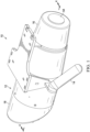
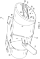
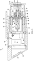
- An external actuation device 10 is generally depicted in FIGS. 1 and 2 and can include a housing 12 and a pair of handles 14 that are attached to the housing 12 and can be grasped by a user to facilitate manual positioning of the external actuation device 10.
- the housing 12 can include a front portion 16 and a rear portion 18.
- a digital display 20 and a plurality of buttons 22 can be disposed on the rear portion 18 of the housing 12.
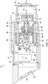
- the external actuation device 10 can include a motor 24 ( FIG. 4 ) and a driving magnet 26 that are at least partially disposed in a receptacle 19 defined by the front portion 16.
- the motor 24 can include a driveshaft 30 that is rotatable about a rotation axis A1 during operation of the motor 24.
- the motor 24 can comprise an electric motor, but any of a variety of suitable alternative motors are contemplated, such as for example, a pneumatic motor or a hydraulic motor.
- the driving magnet 26 can be rotatably coupled with the driveshaft 30 such that the driving magnet 26 is rotatable together with the driveshaft 30 about the rotation axis A1. Rotation of the driving magnet 26 can rotate a driven magnet 32 that is provided under a patient's skin 34 for non-invasively adjusting an implanted medical device (e.g., a distraction rod or a growing rod) (not shown), as will be described in further detail below.
- the driving magnet 26 and the driven magnet 32 can each be permanent axial multipole magnets or alternatively a diametrically magnetized magnet. It is to be appreciated that although the driving magnet 26 and the driven magnet 32 are shown be disc magnets that have substantially the same diameter, any of a variety of different shapes, sizes, and or types of magnets (e.g., cylindrical magnets) can be utilized.
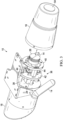
- the external actuation device 10 can include a frame assembly 36 that includes a rear frame member 38, a front frame member 40 and a motor mount 42.
- the rear and front frame members 38, 40 can be coupled together with each other via a plurality of support members 44 that extend though the motor mount 42.
- the housing 12 can be coupled with the rear and front frame members 38, 40.
- the motor 24 can be coupled with the motor mount 42.
- the motor 24 can be slidably coupled with the housing 12 and slidable with respect to the housing 12 along the rotation axis A1 between a retracted position ( FIG. 4 ) and an extended position ( FIG. 5 ).
- the motor mount 42 can be slidably coupled with the support members 44 such that the motor 24, the driving magnet 26 and the motor mount 42 are slidable together along the rotation axis A1.
- the motor mount 42 can include linear bearings 46 provided at the interface between the motor mount 42 and the support members 44 to facilitate sliding therebetween. It is to be appreciated that any of a variety of suitable alternative interfaces can be provided that facilitate sliding between the motor mount 42 and the support members 44.
- the external actuation device 10 can include a linear actuator 50 that facilitates powered sliding of the motor 24 and the driving magnet 26 between the retracted position ( FIG. 4 ) and the extended position ( FIG. 5 ).
- the linear actuator 50 can include a threaded shaft 52 that is threadably coupled with the motor mount 42.
- the threaded shaft 52 can be selectively rotated (e.g., in a clockwise and counterclockwise direction) to facilitate sliding of the motor 24 and the driving magnet 26 between the retracted position and the extended position. It is to be appreciated than any of a variety of suitable alternative actuators are contemplated that facilitate selective sliding of the motor mount 42.
- the driving magnet 26 can be spaced further from an end wall 54 of the front portion 16 of the housing 12 than when the motor 24 and the driving magnet 26 are in the extended position.
- the motor 24 and the driving magnet 26 can initially be placed in the retracted position ( FIG. 4 ) to prevent the driving magnet 26 from inadvertently causing the driven magnet 32 to rotate and to avoid squeezing the patient skin.
- the motor 24 and the driving magnet 26 can be slid towards the extended position until there is sufficient magnetic attraction between the driving magnet 26 and the driven magnet 32 to magnetically couple the driving magnet 26 and the driven magnet 32 together.
- the motor 24 can then be operated to rotate the driven magnet 32 with the driving magnet 26.
- the driving magnet 26 can be slidably coupled with the motor 24 such that the driving magnet 26 can slide relative to the motor 24 along the rotation axis A1.
- the driveshaft 30 can comprise a driving portion 56 and a driven portion 58.
- the driven portion 58 can be slidably and rotatably coupled with the driving portion 56 such that the driven portion 58 rotates together with the driving portion 56 and can slide relative to the driving portion 56.
- the driving portion 56 can include a driving collar 60 and the driven portion 58 can include a driven collar 62 that is spaced from the driving collar 60.
- the driving collar 60 and the driven collar 62 can be rotatably coupled together with a slide pin 64 that extends through each of the driving collar 60 and the driven collar 62.
- the driving portion 56 can be powered by the motor 24 which can in turn rotate the driven portion 58 via the slide pin 64 to rotate the driving magnet 26.
- the driving collar 60 and the driven collar 62 can be slidably coupled together via the slide pin 64, which can allow the driving magnet 26 to slide relative to the motor 24.
- the driving magnet 26 When the driving magnet 26 is acted on by a magnetic force (e.g., from the driven magnet 32), the driving magnet 26 can slide towards or away from the motor 24 (e.g., via the driving collar 60 and the driven collar 62) depending on whether the magnetic force (e.g., from the driven magnet 32) is repulsive or attractive.
- the driving magnet 26 is magnetically coupled to the driven magnet 32, the magnetic force between the driving magnet 26 and the driven magnet 32 is attractive which causes the driving magnet 26 to slide away from the motor 24.
- the driving magnet 26 opposes the driven magnet 32 (e.g., during slip)
- the magnetic force between the driving magnet 26 and the driven magnet 32 is repulsive which causes the driving magnet 26 to slide towards the motor 24.
- any of a variety of suitable slidable arrangements can be utilized to facilitate sliding of the driving magnet 26 with respect to the motor 24.
- the distance that the driving magnet 26 slides with respect to the motor 24 can be proportional to the magnetic attraction between the driving magnet 26 and the driven magnet 32.
- the linear position of the driving magnet 26 can accordingly indicate the integrity of the magnetic coupling between the driving magnet 26 and the driven magnet 32.
- the linear displacement of the driving magnet 26 can indicate whether it is aligned properly with the driven magnet 32. If the driving magnet 26 is aligned properly with the driven magnet 32, the magnetic attraction between the driving magnet 26 and the driven magnet 32 can cause the driving magnet 26 to slide away from the motor 24 enough to indicate that the magnetic coupling between the driving magnet 26 and the driven magnet 32 is sufficient. If the driving magnet 26 is misaligned with the driven magnet 32, the magnetic attraction between the driving magnet 26 and the driven magnet 32 isn't enough to slide the driving magnet 26 sufficiently away from the motor 24, and the driving magnet 26 must be repositioned relative to the driven magnet 32.
- the motor 24 is rotated to rotate the driven magnet 32.
- the linear displacement of the driving magnet 26 can continue to be monitored to determine whether the driving magnet 26 and the driven magnet 32 inadvertently slip.
- the external actuation device 10 can comprise a strain gage 66 that is mounted to the motor mount 42.
- the strain gage 66 can be configured to detect the linear displacement of the driving magnet 26 (e.g., the linear displacement between the driving collar 60 and the driven collar 62) as a function of the position of the driveshaft 30 relative to the motor mount 42.
- the driving magnet 26 is at a neutral position with respect to the motor 24 such that the strain gage 66 is not bent and thus detects no force.
- the driving magnet 26 When the driving magnet 26 is acted on by a magnetic force (e.g., from the driven magnet 32), the driving magnet 26 can slide towards or away from the motor 24 (e.g., via the driving collar 60 and the driven collar 62) in proportional response to a repulsive or attractive magnetic force (e.g., from the driven magnet 32)
- a repulsive or attractive magnetic force e.g., from the driven magnet 32
- the driving magnet 26 is magnetically coupled to the driven magnet 32, the magnetic force acting on the driving magnet causes the driving magnet 26 to move away from the motor 24 thus bending the strain gauge 66 proportionally to the force.
- the magnetic force between the driving magnet 26 and the driven magnet 32 can slide the driving magnet 26 towards the motor 24 which can bend the strain gauge 66 in the opposite direction and proportional to the repulsive magnetic force.
- the strain gage 66 can facilitate biasing of the driving magnet 26 into the neutral position such that when the magnetic force is removed from the driving magnet 26 it automatically returns to the neutral position. It is to be appreciated that any of a variety or quantity of suitable alternative sensors are contemplated and can be placed at any of a variety of locations along the external actuation device 10 to facilitate detection of a magnetic force between the driving magnet 26 and the driven magnet 32.
- a linear displacement sensor can be provided at the driving magnet 26 such that its linear position is detected directly.
- a linear encoder can be provided that is configured to detect a plurality of discrete linear displacement positions of the driving magnet 26.
- a force sensor can be provided. It is also to be appreciated that any of a variety of suitable alternative biasing members can be used for biasing the driving magnet 26 towards the neutral position, such as, for example, a spring or an elastomeric member.
- an accelerometer 67 controller to determine the orientation of the device. For example, if the device is held vertically above the patient, weight of the driving magnet 26 acts on the strain gauge 66 and should be subtracted from the measured force to ensure that only the magnetic force is measured. Conversely, if the device is perfectly horizontal, gravitational force has no effect on the measurement.
- the external actuation device 10 can include a controller 68 that is in communication with the motor 24, the linear actuator 50, and the strain gage 66.
- the controller 68 can be configured to facilitate selective operation of the motor 24 based upon the magnetic force imparted on the driving magnet 26.
- the controller 68 can measure the attractive force between the driving magnet 26 and the driven magnet 32 as a function of the linear position of the driving magnet 26 detected from the strain gage 66.
- the controller 68 can stop the linear actuator 50 to prevent further sliding of the driving magnet 26 into the extended position.
- the controller 68 can then facilitate operation of the motor 24 to rotate the driven magnet 32.
- the motor 24 can comprise a stepper motor that is configured to rotate a precise amount (e.g., defined by a user) based on a command produced by the controller 68.
- the driving magnet 26 can accordingly be rotated a precise amount such that an associated adjustable implant device can be precisely adjusted via the driven magnet 32.
- the controller 68 can measure the integrity of the attractive force between the driving magnet 26 and the driven magnet 32 as a function of the linear position of the driving magnet 26 detected from the strain gage 66. If the driving magnet 26 and the driven magnet 32 begin to slip (e.g., when the torque required to rotate the driven magnet 32 increases), the north/south poles of the driving magnet 26 can begin to align with the north/south poles of the driven magnet 32 which can cause the driving magnet 26 to be temporarily linearly displaced upwardly.
- the controller 68 can deactivate the motor 24 and can issue an audible or visual warning to a user that a problem might exist.
- the controller 68 can compare the linear displacement of the driving magnet 26 to a predefined threshold value that represents the point at which the magnetic coupling becomes unstable.
- the controller 68 can include an accelerometer 70 that facilitates determination of the orientation of the external actuation device 10.
- the controller 68 can account for the orientation of the external actuation device 10 when determining the magnetic force being applied to the driving magnet 26. For example, if the external actuation device 10 is held vertically above the patient, the weight of the driving magnet 26 can act on the strain gauge 66 and the controller 68 can subtract the weight of the driving magnet 26 from the measured force to ensure that only the magnetic force is measured. Conversely, if the device is perfectly horizontal, gravitational force has no effect on the measurement and the controller 68.
- the controller 68 can stop the linear actuator 50 once the driving magnet 26 reaches the extended position and can issue an alert to the user that the external actuation device 10 may need to be repositioned.
- the controller 68 can also be in communication with the digital display 20 and the plurality of buttons 22.
- the controller 68 can be configured to facilitate the presentation of certain operating information to a user on the digital display 20 as will be described in further detail below.
- a user can use the buttons 22 to control the operation of the external actuation device as will be described in further detail below.
- the external actuation device 10 can additionally or alternatively be controlled from a remote computing device (not shown), such as a handheld remote or a smartphone, via a wired or wireless connection. It is also to be appreciated that the external actuation device 10 can be electrically powered from an external power source (e.g., from an electrical wall outlet) and/or from an onboard power storage device, such as a battery.
- an external power source e.g., from an electrical wall outlet
- an onboard power storage device such as a battery.
- FIG. 6 One embodiment of a control routine implemented by the controller 68 during operation of the external actuation device 10 is generally illustrated in FIG. 6 .
- the controller 68 can query the user to input the desired length that the adjustable implanted medical device is to be extended (1010).
- the user can input the amount of desired distance in the controller 68 via the buttons 22 (1020).
- the controller 68 can then prompt the user on the digital display 20 to confirm that the external actuation device 10 has been aligned over the driven magnet 32 (1030).
- the controller 68 can facilitate sliding of the motor 24 and the driving magnet 26 from the retracted position to the extended position (1040).
- the controller 68 can determine whether the attractive force between the driving magnet 26 and the driven magnet 32 (via the strain gage 66) has reached a predefined threshold (1050).
- the predefined threshold can be between about 0.1 N and about 100 N and preferably between about 1 Nm and about 3 Nm.
- the predefined threshold can be selected by a user (via the digital display 20 and the buttons 22). In other embodiments, the predefined threshold can be preset (e.g., from the manufacturer). If the attractive force reaches the predefined threshold before the motor 24 and the driving magnet 26 reach the extended position (1060), the controller 68 can stop the linear actuator 50 to hold the current position of the motor 24 and the driving magnet 26 (1070).
- the motor 24 and the driving magnet 26 can be returned to the retracted position (1080) and the controller 68 can prompt the user again to align the external actuation device 10 over the driven magnet 32 (1030).
- the motor 24 can be operated to rotate the driven magnet (1090).
- the controller 68 can determine (e.g., from the strain gage 66) whether the driving magnet 26 and the driven magnet 32 are slipping (1100). If the driving magnet 26 and the driven magnet 32 are slipping, the motor 24 is stopped and the driving magnet 26 can be returned to the retracted position (1080) and the controller 68 can prompt the user again to align the external actuation device 10 over the driven magnet 32 (1030) to start the process again. If the driving magnet 26 and the driven magnet 32 are not slipping, the controller 68 can continue to operate the motor 24 until the selected distance for the adjustable implanted medical device is reached (1110). Once the selected distance for the adjustable implanted medical device is achieved, the controller 68 can stop the motor 24 and can return the driving magnet 26 to the retracted position (1120) which can end the control routine (1130).
- FIGS. 7 and 8 An alternative embodiment of an external actuation device 110 is illustrated in FIGS. 7 and 8 and can be similar to, or the same in many respects as, the external actuation device 10 illustrated in FIGS. 1-5 .
- the external actuation device 110 can comprise a housing 112 and a motor 124 that is coupled with a motor mount 142.
- a driving magnet 126 can be coupled with a driveshaft 130 of the motor 124.
- a linear displacement sensor 166 can be provided to detect the linear position of the driving magnet 126 as a function of the linear position of the motor mount 142.
- the motor mount 142 can be coupled with the housing 112 by an elastomeric structure 161 or another otherwise flexible structure. When the driving magnet 126 is provided over a driven magnet 132, the elastomeric structure 161 can flex to allow for measuring of the magnetic force acting on the driving magnet via the linear displacement sensor 166.
- the processes associated with the present embodiments may be executed by a controller 68 or other programmable equipment, such as computers.
- Software or other sets of instructions that may be employed to cause programmable equipment to execute the processes may be stored in any storage device, such as, for example, a computer system (non-volatile) memory, an optical disk, magnetic tape, or magnetic disk.
- some of the processes may be programmed when the computer system is manufactured or via a computer-readable memory medium.
- a computer-readable medium may include, for example, memory devices such as diskettes, compact discs of both read-only and read/write varieties, optical disk drives, and hard disk drives.
- a non-transitory computer-readable medium may also include memory storage that may be physical, virtual, permanent, temporary, semi-permanent and/or semi-temporary.
- a “controller” or “processor” may be, for example and without limitation, a processor, microcomputer, minicomputer, server, mainframe, laptop, personal data assistant (PDA), wireless e-mail device, cellular phone, pager, processor, fax machine, scanner, or any other programmable device configured to transmit and/or receive data over a network.
- Computer systems and computer-based devices disclosed herein may include memory for storing certain software applications used in obtaining, processing, and communicating information. It can be appreciated that such memory may be internal or external with respect to operation of the disclosed embodiments.
- the memory may also include any means for storing software, including a hard disk, an optical disk, floppy disk, ROM (read only memory), RAM (random access memory), PROM (programmable ROM), EEPROM (electrically erasable PROM) and/or other computer-readable memory media.
- ROM read only memory
- RAM random access memory
- PROM programmable ROM
- EEPROM electrically erasable PROM
- a single component may be replaced by multiple components, and multiple components may be replaced by a single component, to perform a given function or functions. Except where such substitution would not be operative to practice embodiments of the present invention, such substitution is within the scope of the present invention.
- the systems and methods described herein may be configured and/or programmed to include one or more of the above-described electronic, computer-based elements and components.
- these elements and components may be particularly configured to execute the various rules, algorithms, programs, processes, and method steps described herein.
Landscapes
- Health & Medical Sciences (AREA)
- Orthopedic Medicine & Surgery (AREA)
- Engineering & Computer Science (AREA)
- Life Sciences & Earth Sciences (AREA)
- Surgery (AREA)
- General Health & Medical Sciences (AREA)
- Animal Behavior & Ethology (AREA)
- Nuclear Medicine, Radiotherapy & Molecular Imaging (AREA)
- Veterinary Medicine (AREA)
- Public Health (AREA)
- Biomedical Technology (AREA)
- Heart & Thoracic Surgery (AREA)
- Medical Informatics (AREA)
- Molecular Biology (AREA)
- Physics & Mathematics (AREA)
- Electromagnetism (AREA)
- Neurology (AREA)
- Power Engineering (AREA)
- Robotics (AREA)
- Magnetic Treatment Devices (AREA)
- Reciprocating, Oscillating Or Vibrating Motors (AREA)
- Prostheses (AREA)
- Surgical Instruments (AREA)
Claims (14)
- Externe Betätigungsvorrichtung (10) für eine einstellbare implantierte medizinische Vorrichtung, umfassend:ein Gehäuse (12);einen Motor (24), der eine Antriebswelle (30) umfasst, die um eine Drehachse (A1) drehbar ist;einen Antriebsmagneten (26), der drehbar mit der Antriebswelle gekoppelt ist und zusammen mit der Antriebswelle um die Drehachse drehbar ist;einen Sensor (166), der dem Antriebsmagneten zugeordnet und dazu konfiguriert ist, die Erfassung einer dem Antriebsmagneten zugeführten Magnetkraft zu erleichtern; undeine Steuerung (68) in Kommunikation mit dem Motor und dem Sensor, wobei die Steuerung konfiguriert ist, um einen selektiven Betrieb des Motors auf Grundlage der durch den Sensor erfassten Magnetkraft zu erleichtern;dadurch gekennzeichnet, dass:die Antriebswelle einen Antriebsabschnitt (56) und einen angetriebenen Abschnitt (58) umfasst;der angetriebene Abschnitt drehbar mit dem Antriebsabschnitt gekoppelt ist, sodass sich der angetriebene Abschnitt zusammen mit dem Antriebsabschnitt dreht; undder angetriebene Abschnitt verschiebbar mit dem Antriebsabschnitt gekoppelt ist, sodass der angetriebene Abschnitt relativ zu dem Antriebsabschnitt gleitet.
- Externe Betätigungsvorrichtung nach Anspruch 1, wobei:der Antriebsmagnet verschiebbar mit der Antriebswelle gekoppelt ist, sodass der Antriebsmagnet relativ zu dem Motor entlang der Drehachse gleitet; undder Sensor dazu konfiguriert ist, die Erfassung der Magnetkraft als Funktion der linearen Verschiebung des Antriebsmagneten relativ zum Motor zu erleichtern.
- Externe Betätigungsvorrichtung nach Anspruch 2, wobei der Sensor einen Dehnungsmessstreifen (66) umfasst.
- Externe Betätigungsvorrichtung nach Anspruch 1, wobei der Antriebsmagnet einen oder mehrere von einem axialen Multipolmagneten und einem diametral magnetisierten Permanentmagneten umfasst.
- Externe Betätigungsvorrichtung nach Anspruch 1, wobei der Motor einen Schrittmotor umfasst.
- Externe Betätigungsvorrichtung nach Anspruch 5, wobei:die Steuerung dazu konfiguriert ist, den Schrittmotor mit einem Befehlssignal zu betreiben; unddie Steuerung dazu konfiguriert ist, eine Drehposition des Antriebsmagneten auf Grundlage des Befehlssignals von der Steuerung zu erfassen.
- Externe Betätigungsvorrichtung nach Anspruch 1, ferner umfassend einen Gleitstift (64), der eine drehbare und verschiebbare Kopplung des Antriebsabschnitts und des angetriebenen Abschnitts miteinander erleichtert.
- Externe Betätigungsvorrichtung nach Anspruch 7, wobei:der Antriebsabschnitt einen Antriebskragen (60) umfasst;der angetriebene Abschnitt einen angetriebenen Kragen (62) umfasst, der von dem Antriebskragen beabstandet ist; undder Gleitstift sich zwischen jedem von dem Antriebskragen und dem angetriebenen Kragen erstreckt, um eine drehbare und verschiebbare Kopplung dazwischen zu erleichtern.
- Externe Betätigungsvorrichtung nach Anspruch 1, wobei:der Antriebsmagnet verschiebbar mit dem Gehäuse gekoppelt und entlang der Drehachse relativ zu dem Gehäuse zwischen einer eingefahrenen Position und einer ausgefahrenen Position verschiebbar ist;der Sensor dazu konfiguriert ist, eine Magnetkraft zwischen dem Antriebsmagneten und einem angetriebenen Magneten (32), der benachbart zu dem Antriebsmagneten angeordnet ist, zu erfassen.
- Externe Betätigungsvorrichtung nach Anspruch 9, wobei der Motor und der Antriebsmagnet zusammen relativ zu dem Gehäuse zwischen der eingefahrenen Position und der ausgefahrenen Position verschiebbar sind.
- Externe Betätigungsvorrichtung nach Anspruch 9, ferner umfassend einen Stellantrieb (50), der das Gleiten des Antriebsmagneten zwischen der eingefahrenen Position und der ausgefahrenen Position erleichtert.
- Externe Betätigungsvorrichtung nach Anspruch 11, wobei die Steuerung in Kommunikation mit dem Stellantrieb steht und dazu konfiguriert ist, einen selektiven Betrieb des Stellantriebs auf Grundlage der durch den Sensor erfassten Magnetkraft zu erleichtern.
- Externe Betätigungsvorrichtung nach Anspruch 11, wobei die Steuerung dazu konfiguriert ist, den Betrieb des Stellantriebs einzustellen, sobald eine vordefinierte Magnetkraft zwischen dem Antriebsmagneten und dem angetriebenen Magneten erreicht ist.
- Externe Betätigungsvorrichtung nach Anspruch 8, wobei der Antriebskragen und der angetriebene Kragen jeweils komplementäre Magnete umfassen, die miteinander im Gleichgewicht stehen, so dass der Antriebskragen und der angetriebene Kragen in einer beabstandeten Beziehung relativ zueinander gehalten werden, wenn keine Magnetkraft auf den Antriebsmagneten ausgeübt wird.
Applications Claiming Priority (2)
| Application Number | Priority Date | Filing Date | Title |
|---|---|---|---|
| US201962860061P | 2019-06-11 | 2019-06-11 | |
| PCT/US2020/037271 WO2020252188A1 (en) | 2019-06-11 | 2020-06-11 | External actuation device for adjustable implanted medical device |
Publications (4)
| Publication Number | Publication Date |
|---|---|
| EP3962382A1 EP3962382A1 (de) | 2022-03-09 |
| EP3962382A4 EP3962382A4 (de) | 2023-06-14 |
| EP3962382B1 true EP3962382B1 (de) | 2024-08-07 |
| EP3962382C0 EP3962382C0 (de) | 2024-08-07 |
Family
ID=73746431
Family Applications (1)
| Application Number | Title | Priority Date | Filing Date |
|---|---|---|---|
| EP20821944.4A Active EP3962382B1 (de) | 2019-06-11 | 2020-06-11 | Externe betätigungsvorrichtung für einstellbare implantierte medizinprodukte |
Country Status (7)
| Country | Link |
|---|---|
| US (1) | US11717369B2 (de) |
| EP (1) | EP3962382B1 (de) |
| JP (1) | JP2022536473A (de) |
| AU (1) | AU2020290950A1 (de) |
| BR (1) | BR112021024687A2 (de) |
| CA (1) | CA3139557A1 (de) |
| WO (1) | WO2020252188A1 (de) |
Families Citing this family (2)
| Publication number | Priority date | Publication date | Assignee | Title |
|---|---|---|---|---|
| FR3118404B1 (fr) * | 2020-12-30 | 2022-12-16 | Ecole Nat Superieure De Techniques Avancees | Outil d’activation pour un appareil d’expansion osseuse |
| WO2024025632A2 (en) * | 2022-05-10 | 2024-02-01 | University Of Pittsburgh - Of The Commonwealth System Of Higher Education | Magnetic location detection |
Family Cites Families (5)
| Publication number | Priority date | Publication date | Assignee | Title |
|---|---|---|---|---|
| US7862502B2 (en) * | 2006-10-20 | 2011-01-04 | Ellipse Technologies, Inc. | Method and apparatus for adjusting a gastrointestinal restriction device |
| US11241257B2 (en) | 2008-10-13 | 2022-02-08 | Nuvasive Specialized Orthopedics, Inc. | Spinal distraction system |
| US20120035656A1 (en) | 2010-08-09 | 2012-02-09 | Ellipse Technologies, Inc. | External maintenance feature for magnetic implant |
| US9078711B2 (en) | 2012-06-06 | 2015-07-14 | Ellipse Technologies, Inc. | Devices and methods for detection of slippage of magnetic coupling in implantable medical devices |
| US20160113683A1 (en) * | 2014-04-28 | 2016-04-28 | Ellipse Technologies, Inc. | System for informational magnetic feedback in adjustable implants |
-
2020
- 2020-06-11 EP EP20821944.4A patent/EP3962382B1/de active Active
- 2020-06-11 WO PCT/US2020/037271 patent/WO2020252188A1/en not_active Ceased
- 2020-06-11 AU AU2020290950A patent/AU2020290950A1/en not_active Abandoned
- 2020-06-11 CA CA3139557A patent/CA3139557A1/en active Pending
- 2020-06-11 US US16/899,263 patent/US11717369B2/en active Active
- 2020-06-11 JP JP2021572291A patent/JP2022536473A/ja active Pending
- 2020-06-11 BR BR112021024687A patent/BR112021024687A2/pt not_active Application Discontinuation
Also Published As
| Publication number | Publication date |
|---|---|
| BR112021024687A2 (pt) | 2022-02-15 |
| EP3962382A4 (de) | 2023-06-14 |
| AU2020290950A1 (en) | 2021-11-25 |
| US20200390509A1 (en) | 2020-12-17 |
| JP2022536473A (ja) | 2022-08-17 |
| US11717369B2 (en) | 2023-08-08 |
| EP3962382A1 (de) | 2022-03-09 |
| CA3139557A1 (en) | 2020-12-17 |
| EP3962382C0 (de) | 2024-08-07 |
| WO2020252188A1 (en) | 2020-12-17 |
Similar Documents
| Publication | Publication Date | Title |
|---|---|---|
| EP3962382B1 (de) | Externe betätigungsvorrichtung für einstellbare implantierte medizinprodukte | |
| EP2821188A1 (de) | Positionssteuerungsvorrichtung mit joystick | |
| US11422440B2 (en) | Image stabilization apparatus and control method thereof | |
| US10863883B2 (en) | Medical system and treatment tool calibrating method | |
| EP2665987B1 (de) | Analoge messsonde für eine werkzeugmaschine und betriebsverfahren | |
| AU2013265100B2 (en) | Linear peristaltic pump | |
| CA3065443C (en) | Magnetorheological force retractor | |
| AU2008262348A1 (en) | Syringe infusion pump | |
| JP2022519731A5 (de) | ||
| CA2468613A1 (en) | Pressure gage and switch | |
| WO2016099404A1 (en) | Syringe pump and drive head assembly therefor | |
| JP2020518809A (ja) | 回転軸周りで回転する、アクチュエータの部品、特にクラッチアクチュエータの部品の絶対位置を決定するための方法および装置 | |
| EP3918949A1 (de) | Hautbehandlungssystem | |
| US10830979B2 (en) | Weight balance method of surgical microscope and mechanism thereof | |
| CN107296022B (zh) | 电动渔线轮的电机控制装置 | |
| JP4810667B2 (ja) | ジョイスティックコントローラ | |
| KR20160147140A (ko) | 장애물 검지장치 및 이를 이용한 검지방법 | |
| US20220323292A1 (en) | Control of sexual stimulation devices using motion-sensing controllers | |
| EP2130559B1 (de) | Spritzenpumpe und Andockstation zur Montage an einen Infusionsständer | |
| CN115940746A (zh) | 电机轴向力控制方法及装置 | |
| EP2479530A1 (de) | Analoge Messsonde für Maschinenwerkzeugvorrichtung sowie Betriebsverfahren | |
| EP4535121A1 (de) | Betriebsvorrichtung | |
| JPH0575606U (ja) | 表面粗さ形状測定機及び輪郭形状測定機用アーム退避機構 | |
| US20250012707A1 (en) | Information processing device and information processing method | |
| KR101443012B1 (ko) | 압력센서를 이용한 안전위치제어장치 |
Legal Events
| Date | Code | Title | Description |
|---|---|---|---|
| STAA | Information on the status of an ep patent application or granted ep patent |
Free format text: STATUS: THE INTERNATIONAL PUBLICATION HAS BEEN MADE |
|
| PUAI | Public reference made under article 153(3) epc to a published international application that has entered the european phase |
Free format text: ORIGINAL CODE: 0009012 |
|
| STAA | Information on the status of an ep patent application or granted ep patent |
Free format text: STATUS: REQUEST FOR EXAMINATION WAS MADE |
|
| 17P | Request for examination filed |
Effective date: 20211128 |
|
| AK | Designated contracting states |
Kind code of ref document: A1 Designated state(s): AL AT BE BG CH CY CZ DE DK EE ES FI FR GB GR HR HU IE IS IT LI LT LU LV MC MK MT NL NO PL PT RO RS SE SI SK SM TR |
|
| DAV | Request for validation of the european patent (deleted) | ||
| DAX | Request for extension of the european patent (deleted) | ||
| A4 | Supplementary search report drawn up and despatched |
Effective date: 20230511 |
|
| RIC1 | Information provided on ipc code assigned before grant |
Ipc: A61B 17/00 20060101ALN20230505BHEP Ipc: A61B 90/00 20160101ALI20230505BHEP Ipc: A61B 34/00 20160101ALI20230505BHEP Ipc: A61B 17/72 20060101ALI20230505BHEP Ipc: A61B 17/70 20060101AFI20230505BHEP |
|
| GRAP | Despatch of communication of intention to grant a patent |
Free format text: ORIGINAL CODE: EPIDOSNIGR1 |
|
| STAA | Information on the status of an ep patent application or granted ep patent |
Free format text: STATUS: GRANT OF PATENT IS INTENDED |
|
| RIC1 | Information provided on ipc code assigned before grant |
Ipc: A61B 17/00 20060101ALN20240215BHEP Ipc: H01F 7/02 20060101ALI20240215BHEP Ipc: A61B 90/00 20160101ALI20240215BHEP Ipc: A61B 34/00 20160101ALI20240215BHEP Ipc: A61B 17/72 20060101ALI20240215BHEP Ipc: A61B 17/70 20060101AFI20240215BHEP |
|
| INTG | Intention to grant announced |
Effective date: 20240319 |
|
| GRAS | Grant fee paid |
Free format text: ORIGINAL CODE: EPIDOSNIGR3 |
|
| GRAA | (expected) grant |
Free format text: ORIGINAL CODE: 0009210 |
|
| STAA | Information on the status of an ep patent application or granted ep patent |
Free format text: STATUS: THE PATENT HAS BEEN GRANTED |
|
| AK | Designated contracting states |
Kind code of ref document: B1 Designated state(s): AL AT BE BG CH CY CZ DE DK EE ES FI FR GB GR HR HU IE IS IT LI LT LU LV MC MK MT NL NO PL PT RO RS SE SI SK SM TR |
|
| REG | Reference to a national code |
Ref country code: GB Ref legal event code: FG4D |
|
| REG | Reference to a national code |
Ref country code: CH Ref legal event code: EP |
|
| REG | Reference to a national code |
Ref country code: IE Ref legal event code: FG4D |
|
| REG | Reference to a national code |
Ref country code: DE Ref legal event code: R096 Ref document number: 602020035465 Country of ref document: DE |
|
| U01 | Request for unitary effect filed |
Effective date: 20240807 |
|
| U07 | Unitary effect registered |
Designated state(s): AT BE BG DE DK EE FI FR IT LT LU LV MT NL PT SE SI Effective date: 20240819 |
|
| U1N | Appointed representative for the unitary patent procedure changed after the registration of the unitary effect |
Representative=s name: VALET PATENT SERVICES LIMITED; DE |
|
| PG25 | Lapsed in a contracting state [announced via postgrant information from national office to epo] |
Ref country code: NO Free format text: LAPSE BECAUSE OF FAILURE TO SUBMIT A TRANSLATION OF THE DESCRIPTION OR TO PAY THE FEE WITHIN THE PRESCRIBED TIME-LIMIT Effective date: 20241107 |
|
| PG25 | Lapsed in a contracting state [announced via postgrant information from national office to epo] |
Ref country code: PL Free format text: LAPSE BECAUSE OF FAILURE TO SUBMIT A TRANSLATION OF THE DESCRIPTION OR TO PAY THE FEE WITHIN THE PRESCRIBED TIME-LIMIT Effective date: 20240807 Ref country code: GR Free format text: LAPSE BECAUSE OF FAILURE TO SUBMIT A TRANSLATION OF THE DESCRIPTION OR TO PAY THE FEE WITHIN THE PRESCRIBED TIME-LIMIT Effective date: 20241108 |
|
| PG25 | Lapsed in a contracting state [announced via postgrant information from national office to epo] |
Ref country code: IS Free format text: LAPSE BECAUSE OF FAILURE TO SUBMIT A TRANSLATION OF THE DESCRIPTION OR TO PAY THE FEE WITHIN THE PRESCRIBED TIME-LIMIT Effective date: 20241207 |
|
| PG25 | Lapsed in a contracting state [announced via postgrant information from national office to epo] |
Ref country code: HR Free format text: LAPSE BECAUSE OF FAILURE TO SUBMIT A TRANSLATION OF THE DESCRIPTION OR TO PAY THE FEE WITHIN THE PRESCRIBED TIME-LIMIT Effective date: 20240807 |
|
| PG25 | Lapsed in a contracting state [announced via postgrant information from national office to epo] |
Ref country code: RS Free format text: LAPSE BECAUSE OF FAILURE TO SUBMIT A TRANSLATION OF THE DESCRIPTION OR TO PAY THE FEE WITHIN THE PRESCRIBED TIME-LIMIT Effective date: 20241107 Ref country code: ES Free format text: LAPSE BECAUSE OF FAILURE TO SUBMIT A TRANSLATION OF THE DESCRIPTION OR TO PAY THE FEE WITHIN THE PRESCRIBED TIME-LIMIT Effective date: 20240807 |
|
| PG25 | Lapsed in a contracting state [announced via postgrant information from national office to epo] |
Ref country code: RS Free format text: LAPSE BECAUSE OF FAILURE TO SUBMIT A TRANSLATION OF THE DESCRIPTION OR TO PAY THE FEE WITHIN THE PRESCRIBED TIME-LIMIT Effective date: 20241107 Ref country code: PL Free format text: LAPSE BECAUSE OF FAILURE TO SUBMIT A TRANSLATION OF THE DESCRIPTION OR TO PAY THE FEE WITHIN THE PRESCRIBED TIME-LIMIT Effective date: 20240807 Ref country code: NO Free format text: LAPSE BECAUSE OF FAILURE TO SUBMIT A TRANSLATION OF THE DESCRIPTION OR TO PAY THE FEE WITHIN THE PRESCRIBED TIME-LIMIT Effective date: 20241107 Ref country code: IS Free format text: LAPSE BECAUSE OF FAILURE TO SUBMIT A TRANSLATION OF THE DESCRIPTION OR TO PAY THE FEE WITHIN THE PRESCRIBED TIME-LIMIT Effective date: 20241207 Ref country code: HR Free format text: LAPSE BECAUSE OF FAILURE TO SUBMIT A TRANSLATION OF THE DESCRIPTION OR TO PAY THE FEE WITHIN THE PRESCRIBED TIME-LIMIT Effective date: 20240807 Ref country code: GR Free format text: LAPSE BECAUSE OF FAILURE TO SUBMIT A TRANSLATION OF THE DESCRIPTION OR TO PAY THE FEE WITHIN THE PRESCRIBED TIME-LIMIT Effective date: 20241108 Ref country code: ES Free format text: LAPSE BECAUSE OF FAILURE TO SUBMIT A TRANSLATION OF THE DESCRIPTION OR TO PAY THE FEE WITHIN THE PRESCRIBED TIME-LIMIT Effective date: 20240807 |
|
| PG25 | Lapsed in a contracting state [announced via postgrant information from national office to epo] |
Ref country code: SM Free format text: LAPSE BECAUSE OF FAILURE TO SUBMIT A TRANSLATION OF THE DESCRIPTION OR TO PAY THE FEE WITHIN THE PRESCRIBED TIME-LIMIT Effective date: 20240807 |
|
| PG25 | Lapsed in a contracting state [announced via postgrant information from national office to epo] |
Ref country code: CZ Free format text: LAPSE BECAUSE OF FAILURE TO SUBMIT A TRANSLATION OF THE DESCRIPTION OR TO PAY THE FEE WITHIN THE PRESCRIBED TIME-LIMIT Effective date: 20240807 |
|
| PG25 | Lapsed in a contracting state [announced via postgrant information from national office to epo] |
Ref country code: SK Free format text: LAPSE BECAUSE OF FAILURE TO SUBMIT A TRANSLATION OF THE DESCRIPTION OR TO PAY THE FEE WITHIN THE PRESCRIBED TIME-LIMIT Effective date: 20240807 |
|
| PLBE | No opposition filed within time limit |
Free format text: ORIGINAL CODE: 0009261 |
|
| STAA | Information on the status of an ep patent application or granted ep patent |
Free format text: STATUS: NO OPPOSITION FILED WITHIN TIME LIMIT |
|
| 26N | No opposition filed |
Effective date: 20250508 |
|
| U20 | Renewal fee for the european patent with unitary effect paid |
Year of fee payment: 6 Effective date: 20250628 |
|
| PGFP | Annual fee paid to national office [announced via postgrant information from national office to epo] |
Ref country code: CH Payment date: 20250701 Year of fee payment: 6 |
|
| PG25 | Lapsed in a contracting state [announced via postgrant information from national office to epo] |
Ref country code: MC Free format text: LAPSE BECAUSE OF FAILURE TO SUBMIT A TRANSLATION OF THE DESCRIPTION OR TO PAY THE FEE WITHIN THE PRESCRIBED TIME-LIMIT Effective date: 20240807 |
|
| GBPC | Gb: european patent ceased through non-payment of renewal fee |
Effective date: 20250611 |
|
| PG25 | Lapsed in a contracting state [announced via postgrant information from national office to epo] |
Ref country code: GB Free format text: LAPSE BECAUSE OF NON-PAYMENT OF DUE FEES Effective date: 20250611 |
|
| PG25 | Lapsed in a contracting state [announced via postgrant information from national office to epo] |
Ref country code: IE Free format text: LAPSE BECAUSE OF NON-PAYMENT OF DUE FEES Effective date: 20250611 |
|
| PG25 | Lapsed in a contracting state [announced via postgrant information from national office to epo] |
Ref country code: RO Free format text: LAPSE BECAUSE OF FAILURE TO SUBMIT A TRANSLATION OF THE DESCRIPTION OR TO PAY THE FEE WITHIN THE PRESCRIBED TIME-LIMIT Effective date: 20240807 |