EP3962256A1 - Cooling device for a vehicle electronic control unit and controller for operating the same - Google Patents
Cooling device for a vehicle electronic control unit and controller for operating the same Download PDFInfo
- Publication number
- EP3962256A1 EP3962256A1 EP21186813.8A EP21186813A EP3962256A1 EP 3962256 A1 EP3962256 A1 EP 3962256A1 EP 21186813 A EP21186813 A EP 21186813A EP 3962256 A1 EP3962256 A1 EP 3962256A1
- Authority
- EP
- European Patent Office
- Prior art keywords
- fans
- heat dissipating
- cooling device
- ecu
- face
- Prior art date
- Legal status (The legal status is an assumption and is not a legal conclusion. Google has not performed a legal analysis and makes no representation as to the accuracy of the status listed.)
- Granted
Links
Images

Classifications
-
- H—ELECTRICITY
- H05—ELECTRIC TECHNIQUES NOT OTHERWISE PROVIDED FOR
- H05K—PRINTED CIRCUITS; CASINGS OR CONSTRUCTIONAL DETAILS OF ELECTRIC APPARATUS; MANUFACTURE OF ASSEMBLAGES OF ELECTRICAL COMPONENTS
- H05K7/00—Constructional details common to different types of electric apparatus
- H05K7/20—Modifications to facilitate cooling, ventilating, or heating
- H05K7/20845—Modifications to facilitate cooling, ventilating, or heating for automotive electronic casings
- H05K7/20854—Heat transfer by conduction from internal heat source to heat radiating structure
-
- H—ELECTRICITY
- H05—ELECTRIC TECHNIQUES NOT OTHERWISE PROVIDED FOR
- H05K—PRINTED CIRCUITS; CASINGS OR CONSTRUCTIONAL DETAILS OF ELECTRIC APPARATUS; MANUFACTURE OF ASSEMBLAGES OF ELECTRICAL COMPONENTS
- H05K7/00—Constructional details common to different types of electric apparatus
- H05K7/20—Modifications to facilitate cooling, ventilating, or heating
- H05K7/2039—Modifications to facilitate cooling, ventilating, or heating characterised by the heat transfer by conduction from the heat generating element to a dissipating body
-
- H—ELECTRICITY
- H05—ELECTRIC TECHNIQUES NOT OTHERWISE PROVIDED FOR
- H05K—PRINTED CIRCUITS; CASINGS OR CONSTRUCTIONAL DETAILS OF ELECTRIC APPARATUS; MANUFACTURE OF ASSEMBLAGES OF ELECTRICAL COMPONENTS
- H05K7/00—Constructional details common to different types of electric apparatus
- H05K7/20—Modifications to facilitate cooling, ventilating, or heating
- H05K7/20009—Modifications to facilitate cooling, ventilating, or heating using a gaseous coolant in electronic enclosures
- H05K7/20209—Thermal management, e.g. fan control
-
- H—ELECTRICITY
- H05—ELECTRIC TECHNIQUES NOT OTHERWISE PROVIDED FOR
- H05K—PRINTED CIRCUITS; CASINGS OR CONSTRUCTIONAL DETAILS OF ELECTRIC APPARATUS; MANUFACTURE OF ASSEMBLAGES OF ELECTRICAL COMPONENTS
- H05K5/00—Casings, cabinets or drawers for electric apparatus
- H05K5/02—Details
- H05K5/0217—Mechanical details of casings
-
- H—ELECTRICITY
- H05—ELECTRIC TECHNIQUES NOT OTHERWISE PROVIDED FOR
- H05K—PRINTED CIRCUITS; CASINGS OR CONSTRUCTIONAL DETAILS OF ELECTRIC APPARATUS; MANUFACTURE OF ASSEMBLAGES OF ELECTRICAL COMPONENTS
- H05K7/00—Constructional details common to different types of electric apparatus
- H05K7/20—Modifications to facilitate cooling, ventilating, or heating
- H05K7/20009—Modifications to facilitate cooling, ventilating, or heating using a gaseous coolant in electronic enclosures
- H05K7/20136—Forced ventilation, e.g. by fans
-
- H—ELECTRICITY
- H05—ELECTRIC TECHNIQUES NOT OTHERWISE PROVIDED FOR
- H05K—PRINTED CIRCUITS; CASINGS OR CONSTRUCTIONAL DETAILS OF ELECTRIC APPARATUS; MANUFACTURE OF ASSEMBLAGES OF ELECTRICAL COMPONENTS
- H05K7/00—Constructional details common to different types of electric apparatus
- H05K7/20—Modifications to facilitate cooling, ventilating, or heating
- H05K7/20009—Modifications to facilitate cooling, ventilating, or heating using a gaseous coolant in electronic enclosures
- H05K7/20136—Forced ventilation, e.g. by fans
- H05K7/20154—Heat dissipaters coupled to components
-
- H—ELECTRICITY
- H05—ELECTRIC TECHNIQUES NOT OTHERWISE PROVIDED FOR
- H05K—PRINTED CIRCUITS; CASINGS OR CONSTRUCTIONAL DETAILS OF ELECTRIC APPARATUS; MANUFACTURE OF ASSEMBLAGES OF ELECTRICAL COMPONENTS
- H05K7/00—Constructional details common to different types of electric apparatus
- H05K7/20—Modifications to facilitate cooling, ventilating, or heating
- H05K7/2039—Modifications to facilitate cooling, ventilating, or heating characterised by the heat transfer by conduction from the heat generating element to a dissipating body
- H05K7/20409—Outer radiating structures on heat dissipating housings, e.g. fins integrated with the housing
-
- H—ELECTRICITY
- H05—ELECTRIC TECHNIQUES NOT OTHERWISE PROVIDED FOR
- H05K—PRINTED CIRCUITS; CASINGS OR CONSTRUCTIONAL DETAILS OF ELECTRIC APPARATUS; MANUFACTURE OF ASSEMBLAGES OF ELECTRICAL COMPONENTS
- H05K7/00—Constructional details common to different types of electric apparatus
- H05K7/20—Modifications to facilitate cooling, ventilating, or heating
- H05K7/20845—Modifications to facilitate cooling, ventilating, or heating for automotive electronic casings
- H05K7/20863—Forced ventilation, e.g. on heat dissipaters coupled to components
Definitions
- large fans typically have a large central hub to support the blades, which results in a low airflow region directly below the hub.
- the controller is configured for controlling the fans based on at least measured fan speed of individual ones of the plurality of fans.
- the controller is configured for controlling the plurality of fans to compensate for performance differences between the fans.
- the heat dissipating face comprises a plurality of mounting formations to which the plurality of fans are mounted, wherein the mounting formations are configured for locating the fans over regions of the heat dissipating face associated with active components of the ECU.
- a fourth aspect there is provided method for controlling a cooling device according to any of the above statements, the method including: determining temperature values associated with the respective regions of the heat dissipating face; and generating individual control signals for the plurality of fans for driving each fan at a speed for cooling the respective region of the heat dissipating face.
- the fan controller 13 may read the fan speed sensor values and compare the actual fan speed with the driven values dictated in the look-up table. If the controller 13 determines that the actual fan speed is lower than desired, this may be logged as a potential fan malfunction.
- the redundant fan 2c may be activated or its speed increased to compensate. For example, if fan 2b malfunctions, adjacent fan 2c may be activated to enhance cooling through cooling region 6c. The controller may also increase the speed of the other adjacent fans 2a and 2d to further compensate and maintain overall cooling performance.
- the controller 13 may additionally generate and store an error message identifying the fan malfunction for maintenance purposes.
Landscapes
- Engineering & Computer Science (AREA)
- Microelectronics & Electronic Packaging (AREA)
- Physics & Mathematics (AREA)
- Thermal Sciences (AREA)
- Cooling Or The Like Of Electrical Apparatus (AREA)
- Cooling Or The Like Of Semiconductors Or Solid State Devices (AREA)
Abstract
Description
- The present disclosure relates to a cooling device for cooling a plurality of electronic components mounted on a vehicle electronic control unit (ECU). The present disclosure is particularly relevant to a fan cooling system for automotive applications and most particularly to multi domain controllers (MDCs).
- Some electronics components get hot during operation, which can subsequently compromise their function or lead to component damage. As such, it is common to fit cooling devices to electronic circuitry to maintain their operating temperature within an acceptable tolerance. These cooling systems are particularly important in automotive applications because the Multi-domain controllers (MDC) and other types of electronic control units (ECU) used in modern vehicles perform critical vehicle control and safety functions. This is especially true in vehicles having autonomous driving capabilities where processing demands of electronic components are high and maintaining operating integrity is particularly essential.
- Depending on the level of dissipated electrical power, cooling systems for cooling active components typically rely on forced-air or forced-liquid cooling to achieve the required cooling performance for maintaining an acceptable operating temperature. However, electronic systems in automotive applications also have further specific requirements in terms of electromagnetic shielding, and dust and moisture protection. As such, ECU devices will typically need to be encapsulated in a casing which provides electromagnetic, water and dust protection, but consequently also prevents direct contact between the ECU and cooling liquids or gases. As such, conventional ECU cooling systems will normally employ a combination of passive heat transfer through the housing to the ambient, along with a liquid cooling circuit to provide high efficiency cooling through the housing to active components.
- Forced-air cooling systems are rarely used for ECU applications. Although such forced-air systems potentially offer advantages in terms of reduced complexity, as well as cost and weight savings, conventional systems have a number of disadvantages which have prevented their wider adoption. For example, systems have been proposed which employ an axial or radial fan attached on the ECU for moving air over the housing surface. However, a fan capable of generating sufficient cooling airflow is relatively large and hence increases the overall dimensions of ECU assembly. At the same time, driving at higher fan speeds leads to increased noise and, in the event that the fan malfunctions or is damaged by the intrusion of an object, cooling may be stopped altogether. There are also issues associated with the evenness of the air stream generated by a fan. For instance, large fans typically have a large central hub to support the blades, which results in a low airflow region directly below the hub. At the same time, it is typical to mount a fan centrally over an ECU's housing, which often locates this low airflow region over or adjacent to the ECU's main System-on-a-Chip component. As such, a critical component of the ECU would be subjected to ineffective cooling.
- There therefore remains a need in automotive industry for an improved forced-air cooling device for cooling an ECU.
- The present disclosure concerns a cooling device and controller for a cooling device for cooling a vehicle ECU. The present disclosure particularly concerns a cooling device and controller for a cooling device for cooling a multi domain controller (MDC). For example, the cooling device may be for use with an autonomous driving MDC.
- According to a first aspect, there is provided a cooling device for a vehicle electronic control unit, ECU, including: a casing for covering the ECU and having a heat absorbing face for absorbing heat from components of the ECU and a heat dissipating face for dissipating absorbed heat; and a plurality of fans mounted to the heat dissipating face and arranged for directing airflow over respective regions of the heat dissipating face, wherein the fans are independently controllable for being driven at different speeds to vary the cooling of the respective regions of the heat dissipating face.
- In this way, a grid-array of smaller independent cooling fans may be used for cooling an ECU, rather than a single large fan. This not only allows for improved cooling efficiency, but also provides for enhanced reliability by allowing other fans in the array to compensate in the event of a fan malfunction.
- In embodiments, the cooling device further comprises a plurality of temperature sensors for determining a temperature associated with the respective regions of the heat dissipating face.
- In embodiments, the plurality of temperature sensors are provided on the heat absorbing face of the casing. In other embodiments, the temperature sensors may be integrated into the ECU electronics. The temperature sensors may be thermistors.
- In embodiments, the cooling device further comprises fan speed sensors for measuring the fan speed of individual ones of the plurality of fans. In this way, feedback of the actual fan rotation speed may be provided for diagnostic or fault detection purposes.
- In embodiments, the cooling device further comprises a controller for controlling the fans. In embodiments, the controller may be integrated into the ECU.
- In embodiments, the controller is configured for controlling the fans based on at least determined temperature values associated with the respective regions of the heat dissipating face.
- In embodiments, the determined temperature values are based on measured temperatures at the respective regions of the heat dissipating face. In embodiments, the determined temperature values are based on temperature sensor measurements. In other embodiments, the temperature values may be determined based on predicted temperature values. For example, temperature values may be estimated based on the operating state of the ECU.
- In embodiments, the controller is configured for controlling the fans based on at least measured fan speed of individual ones of the plurality of fans.
- In embodiments, the controller is configured for controlling the plurality of fans to compensate for performance differences between the fans.
- In embodiments, the plurality of fans comprises a backup fan activatable for compensating for a drop in performance of one of the other plurality of fans.
- In embodiments, the heat dissipating face comprises a plurality of cooling fins for directing airflow from the plurality of fans. The cooling fins may thereby act to dissipate heat transferred through the casing from the ECU. The cooling fins may be arranged in clusters defining cooling regions of the casing. The cooling regions may be linked by air pathways to allow airflow generated by the fans to flow between regions.
- In embodiments, the heat dissipating face comprises a plurality of mounting formations to which the plurality of fans are mounted, wherein the mounting formations are configured for locating the fans over regions of the heat dissipating face associated with active components of the ECU.
- According to a second aspect, there is provided an electronic control unit, ECU, assembly for a vehicle, including: an ECU having a plurality of components mounted to a circuit board; a casing for covering the ECU and having a heat absorbing face for absorbing heat from the components and a heat dissipating face for dissipating absorbed heat; a plurality of fans mounted to the heat dissipating face and arranged for directing airflow over respective regions of the heat dissipating face; and a controller for independently controlling the fans to drive them at different speeds for varying the cooling of the respective regions of the heat dissipating face.
- According to a third aspect, there is provided a controller for controlling a cooling device according to any of the above statements, the controller including: a temperature determination module for determining temperature values associated with the respective regions of the heat dissipating face; a control signal module for generating individual control signals for the plurality of fans for driving each fan at a speed for cooling the respective region of the heat dissipating face.
- According to a fourth aspect, there is provided method for controlling a cooling device according to any of the above statements, the method including: determining temperature values associated with the respective regions of the heat dissipating face; and generating individual control signals for the plurality of fans for driving each fan at a speed for cooling the respective region of the heat dissipating face.
- According to a fifth aspect, there is provided software including instructions for implementing the above method. The software may be stored on a non-transitory computer readable medium.
- Illustrative embodiments will now be described with reference to the accompanying drawings in which:
-
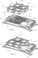
Figure 1 shows an isometric view of a cooling device, with the casing and fan array separated, according to a first embodiment; -
Figure 2 shows an isometric view of the cooling device shown inFigure 1 , with the fan array connected to the casing; -
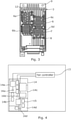
Figure 3 shows a top view of the casing shown inFigure 1 ; -
Figure 4 shows a schematic top view of an ECU circuit board relative to the temperature sensors of the cooling device of the first embodiment; -
Figure 5 shows a schematic cross-sectional view of the cooling device of the first embodiment; and -
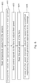
Figure 6 shows a flow diagram of the control algorithm employed by the fan controller. -
Figure 1 shows an isometric view of acooling device 1 according to a first embodiment. Thecooling device 1 comprises acasing 3 which fits over a vehicle Electronic Control Unit (ECU) andfan array 2, which is mounted to theupper surface 6 of thecasing 3 when assembled, as shown inFigure 2 . - In this embodiment, the
fan array 2 comprises fourfans fan upper surface 6 of thecasing 3 once thefan array 2 is mounted to thecasing 3. In this embodiment, thefans upper surface 6 of thecasing 3 when driven. In other embodiments, the airflow may be reversed such that thefans upper surface 6. - The
upper surface 6 of thecasing 3 comprises a plurality of mountingformations 8 to which thefans 2 are seated and fixed inplace using screws 5, as shown inFigure 2 . As shown inFigures 1 and3 , theupper surface 6 comprises a plurality of heat dissipating fins 7 which are located beneath thefans casing 3. As such, airflow driven by the fans is forced over and around the heat dissipating fins 7 for transferring heat from the fins 7 into the air.Linear fins 12 are provided either side of the heat dissipating fins 7 to form airflow paths for feeding or exhausting air from the heat dissipating fins 7, depending on the driving direction of thefans 2. - The
casing 3 is formed of a thermally conductive material, such as a metal or metal alloy, and further comprises acoupling 9 for fixture to the ECU. For example, the ECU's circuit board may be mounted to a base plate which connects to thecouplings 9 to form a housing around the ECU. Once mounted to the circuit board, thecasing 3 provides a protective cover for the ECU. At the same time, thebottom surface 11 of thecasing 3 faces the electronic components on the ECU circuit board and acts to absorb heat therefrom. This absorbed heat is then conducted to theupper surface 6, from where it may be dissipated. - In this connection, once the fans are mounted to their
respective mounting formations 8, they define fourcooling regions upper surface 6 of thecasing 3, as shown infigure 3 . Thesecooling regions upper surface 6 of thecasing 3 may dissipate heat, heat dissipation will be particularly effective in thecooling regions fans cooling regions -
Figure 4 shows a schematic top view of the ECU circuit board 4 and thetemperature sensors 16 relative to this. In this embodiment, threetemperature sensors fan controller 13, which then controls thefan array 2 in response thereto. The threetemperature sensors bottom surface 11 of thecasing 3 such that they align with defined positions on thecircuit board 14 when thecasing 3 is fitted. Thecooling regions casing 3 define fourcircuit regions circuit board 14. The threetemperature sensors respective circuit regions components 15 located within thesecircuit regions temperature sensors - In this embodiment, the remaining
circuit region 14c without an associated temperature sensor comprises components which are passive or less sensitive to higher operating temperatures. However, the associatedcooling region 6c andfan 2c provides a redundancy in the event that one of theother fans fan 2c may provide a back up to enhance cooling withincooling region 6c, which may then compensate for a loss of cooling efficiency in anadjacent cooling region region 6c may also be configured to direct airflow from thefan 2c to theadjacent cooling regions active components 15 within the associatedcircuit regions fans -
Figure 5 shows a schematic cross-sectional view of thecooling device 1. In this embodiment, thebottom surface 11 of thecasing 3 is provided withpedestals 10 which project down toward the ECU circuit board to facilitate heat transfer. Thepedestals 10 may also mate with the top surfaces ofcomponents 15. In this embodiment, thetemperature sensors 16 are located within thepedestals 10 and feedback to thefan controller 13. In turn, thefan controller 13 drives the fans within thefan array 2, which are seated over the heat dissipating fins 7. At the same time, the fans provide fan speed feedback to thecontroller 13 based on the detected fan speed. -
Figure 6 shows a flow diagram of the control algorithm employed by thefan controller 13 during normal operation. Initially, thefan array 2 may be activated so that all the fans are set to a default speed. Instep 601, thecontroller 13 reads the temperature values at each of thetemperature sensors 16. Instep 602, the detected temperature values are compared with threshold values stored in a look-up table within the controller's memory, or may otherwise be analysed according controller software algorithms. Instep 603, the controller may then independently adjust each fan's speed according to the optimised settings specified in the look-up table. For example, if components withincircuit region 14b are getting hot, the speed offan 2b may be accelerated. Equally,fan 2c, which is mounted above thecircuit region 14c that requires no cooling, can be decreased to zero. - In
step 604, thefan controller 13 may read the fan speed sensor values and compare the actual fan speed with the driven values dictated in the look-up table. If thecontroller 13 determines that the actual fan speed is lower than desired, this may be logged as a potential fan malfunction. Instep 605, where a malfunctioning fan is detected, theredundant fan 2c may be activated or its speed increased to compensate. For example, iffan 2b malfunctions,adjacent fan 2c may be activated to enhance cooling throughcooling region 6c. The controller may also increase the speed of the otheradjacent fans controller 13 may additionally generate and store an error message identifying the fan malfunction for maintenance purposes. - As discussed above, in this embodiment, the
controller 13 may determine adjustments to fan speed based on the current temperature readings provided bytemperature sensors 16. As such, the speed of eachfan controller 13 may also or alternatively utilise a predictive algorithm based on the current state of the ECU. For example, when the activity state of the ECU increases due to processing demands, the predicted temperature values may be used by the controller to determine fan speed settings. These predicted temperature values may be based, for example, on historical data or pre-defined in a look-up table. As such, in response to a change in state of ECU components, thecontroller 13 may pre-emptively increase cooling withinrelevant cooling regions - Accordingly, with the above described embodiments, two or more smaller fans are utilised in a fan-grid array to provide cooling, rather than a single large fan. As such, the fans may be located to focus their airflow on locations of the ECU casing which particularly require cooling, for instance directly above circuit hot spots. The fan speeds may therefore be controlled according to the actual cooling needs of the respective region of the ECU circuit. At the same time, the use of the fan-grid array may minimise the low air flow regions associated with larger fans, thereby allowing for improved cooling uniformity overall.
- The use of smaller fans also provides for a smaller assembly size and lower noise generation. For instance, fans with a smaller diameter are available with a lower fan height, which allows the overall height of the ECU package to be reduced. A higher air flow volume can be created compared to a single larger fan, thereby allowing operation at relatively lower fan speeds. Equally, the focused cooling may allow one or more of the fans to be deactivated or run at very low speeds. These factors help to minimise the noise that would otherwise be generated at higher fan speeds.
- Finally, the built-in redundancy provided by having multiple fans allows for enhanced robustness towards malfunction. Faults are also less likely because, not only may individual fans be deactivated when non-needed which allows their mechanical lifespan to be preserved, but the smaller fans also have smaller blade separations. This thereby reduces the chance of objects from blocking the fan. As such, the cooling device may provide for increased ECU reliability.
- It will be understood that the embodiments illustrated above show applications only for the purposes of illustration. In practice, embodiments may be applied to many different configurations, the detailed embodiments being straightforward for those skilled in the art to implement.
- For example, although in the above embodiment an independent fan controller is described, it will be understood that the fan control algorithm may be implemented using the ECU. For example, an ECU assembly may be provided, which includes both the ECU and the cooling device, with the controller being integrated into the ECU electronics. Equally, although the temperature sensors have been described as independent sensors integrated into the casing, internal sensors within the ECU components may be used.
- On the casing itself, although the heat dissipating fins have been illustrated as pin projections, it will be understood that different fin configurations are also possible. For example, a number of higher pin fins may be additional provided which extend above the tops of the fans such that the fans are seated between the higher fins. This may thereby provide some mechanical impact protection for the fans.
Claims (15)
- A cooling device for a vehicle electronic control unit, ECU, comprising:a casing for covering the ECU and having a heat absorbing face for absorbing heat from components of the ECU and a heat dissipating face for dissipating absorbed heat; anda plurality of fans mounted to the heat dissipating face and arranged for directing airflow over respective regions of the heat dissipating face,wherein the fans are independently controllable for being driven at different speeds to vary the cooling of the respective regions of the heat dissipating face.
- A cooling device according to claim 1, further comprising a plurality of temperature sensors for determining a temperature associated with the respective regions of the heat dissipating face.
- A cooling device according to claim 2, wherein the plurality of temperature sensors are provided on the heat absorbing face of the casing.
- A cooling device according to any preceding claim, further comprising fan speed sensors for measuring the fan speed of individual ones of the plurality of fans.
- A cooling device according to any preceding claim, further comprising a controller for controlling the fans.
- A cooling device according to claim 5, wherein the controller is configured for controlling the fans based on at least determined temperature values associated with the respective regions of the heat dissipating face.
- A cooling device according to claim 6, wherein the determined temperature values are based on measured temperatures at the respective regions of the heat dissipating face.
- A cooling device according to claim 7, wherein the determined temperature values are based on temperature sensor measurements.
- A cooling device according to any of claims 5 to 8, wherein the controller is configured for controlling the fans based on at least measured fan speed of individual ones of the plurality of fans.
- A cooling device according to any of claims 5 to 9, wherein the controller is configured for controlling the plurality of fans to compensate for performance differences between the fans.
- A cooling device according to any preceding claim, wherein the plurality of fans comprises a backup fan activatable for compensating for a drop in performance of one of the other plurality of fans.
- A cooling device according to any preceding claim, wherein the heat dissipating face comprises a plurality of cooling fins for directing airflow from the plurality of fans.
- A cooling device according to any preceding claim, wherein the heat dissipating face comprises a plurality of mounting formations to which the plurality of fans are mounted, wherein the mounting formations are configured for locating the fans over regions of the heat dissipating face associated with active components of the ECU.
- An electronic control unit, ECU, assembly for a vehicle, comprising:an ECU having a plurality of components mounted to a circuit board;a casing for covering the ECU and having a heat absorbing face for absorbing heat from the components and a heat dissipating face for dissipating absorbed heat;a plurality of fans mounted to the heat dissipating face and arranged for directing airflow over respective regions of the heat dissipating face; anda controller for independently controlling the fans to drive them at different speeds for varying the cooling of the respective regions of the heat dissipating face.
- A controller for controlling a cooling device according to any of claims 1 to 13, the controller comprising:a temperature determination module for determining temperature values associated with the respective regions of the heat dissipating face;a control signal module for generating individual control signals for the plurality of fans for driving each fan at a speed for cooling the respective region of the heat dissipating face.
Applications Claiming Priority (1)
| Application Number | Priority Date | Filing Date | Title |
|---|---|---|---|
| GB2013681.8A GB2598391A (en) | 2020-09-01 | 2020-09-01 | Cooling device for a vehicle electronic control unit and controller for operating the same |
Publications (2)
| Publication Number | Publication Date |
|---|---|
| EP3962256A1 true EP3962256A1 (en) | 2022-03-02 |
| EP3962256B1 EP3962256B1 (en) | 2025-10-08 |
Family
ID=72749545
Family Applications (1)
| Application Number | Title | Priority Date | Filing Date |
|---|---|---|---|
| EP21186813.8A Active EP3962256B1 (en) | 2020-09-01 | 2021-07-20 | Cooling device for a vehicle electronic control unit and controller for operating the same |
Country Status (4)
| Country | Link |
|---|---|
| US (1) | US12144144B2 (en) |
| EP (1) | EP3962256B1 (en) |
| CN (2) | CN114126338A (en) |
| GB (1) | GB2598391A (en) |
Families Citing this family (6)
| Publication number | Priority date | Publication date | Assignee | Title |
|---|---|---|---|---|
| GB2598391A (en) * | 2020-09-01 | 2022-03-02 | Aptiv Tech Ltd | Cooling device for a vehicle electronic control unit and controller for operating the same |
| JP2024061014A (en) * | 2022-10-20 | 2024-05-07 | ソフトバンクグループ株式会社 | Synchronized Burst Chilling |
| WO2024075749A1 (en) * | 2022-10-04 | 2024-04-11 | ソフトバンクグループ株式会社 | Cooling system, cooling execution device, cooling device, cooling execution method, cooling method, program, cooling execution program, and cooling program |
| JP2024053999A (en) * | 2022-10-04 | 2024-04-16 | ソフトバンクグループ株式会社 | Instantaneous cooling system for SoC (System on Chip) Boxes for autonomous vehicles |
| TW202419804A (en) * | 2022-10-31 | 2024-05-16 | 技嘉科技股份有限公司 | Heat dissipation control system for multiple areas of water cooling radiator and water cooling heat sink system with the same |
| JP2025154881A (en) * | 2024-03-29 | 2025-10-10 | 市光工業株式会社 | Vehicle image display device |
Citations (5)
| Publication number | Priority date | Publication date | Assignee | Title |
|---|---|---|---|---|
| US5638895A (en) * | 1996-03-25 | 1997-06-17 | Dodson; Douglas A. | Twin fan cooling device |
| US5953209A (en) * | 1997-12-15 | 1999-09-14 | Intel Corporation | Push and pull dual-fan heat sink design |
| US20090116189A1 (en) * | 2007-11-06 | 2009-05-07 | Compucase Enterprise Co., Ltd. (Taiwan) | Cooling System for a Computer Power Supply Unit |
| EP3373716A1 (en) * | 2017-03-09 | 2018-09-12 | Delphi Technologies LLC | Electronic device for a motor vehicle |
| DE202020103473U1 (en) * | 2020-04-22 | 2020-07-21 | Song Gao | Motor vehicle ECU control unit |
Family Cites Families (20)
| Publication number | Priority date | Publication date | Assignee | Title |
|---|---|---|---|---|
| US5787971A (en) * | 1996-03-25 | 1998-08-04 | Dodson; Douglas A. | Multiple fan cooling device |
| JPH10224061A (en) * | 1997-02-10 | 1998-08-21 | Matsushita Electric Ind Co Ltd | Heat sink unit and electronic equipment |
| US6407925B1 (en) * | 1999-09-17 | 2002-06-18 | Denso Corporation | Casing for electronic control devices |
| US6463891B2 (en) * | 1999-12-17 | 2002-10-15 | Caterpillar Inc. | Twin fan control system and method |
| EP1378090B1 (en) | 2001-02-24 | 2007-07-18 | International Business Machines Corporation | Data capture technique for high speed signaling |
| JP2005322757A (en) * | 2004-05-07 | 2005-11-17 | Sony Corp | Cooling device and electronic equipment |
| US7277282B2 (en) * | 2004-12-27 | 2007-10-02 | Intel Corporation | Integrated circuit cooling system including heat pipes and external heat sink |
| FR2917567A1 (en) | 2007-06-12 | 2008-12-19 | Alcatel Lucent Sas | COOLING DEVICE FOR ELECTRONIC EQUIPMENT BOX. |
| US7967059B2 (en) * | 2008-09-30 | 2011-06-28 | Fu Zhun Precision Industry (Shen Zhen) Co., Ltd. | Heat dissipation device |
| CN201895566U (en) * | 2010-03-30 | 2011-07-13 | 广州大华德盛科技有限公司 | Heat management system of motor-driven fan for vehicle |
| CN103186207A (en) * | 2011-12-28 | 2013-07-03 | 鸿富锦精密工业(深圳)有限公司 | Radiation system and control method applied to same |
| US10426063B2 (en) | 2015-02-03 | 2019-09-24 | Dell Products, L.P. | System and method for cooling an information handling system |
| WO2017137669A1 (en) * | 2016-02-09 | 2017-08-17 | Alstom Transport Technologies | Cooling module for an electrical power supply compartment of a railway vehicle, and related electrical power supply compartment and railway vehicle |
| US10450939B2 (en) | 2016-04-28 | 2019-10-22 | Deere & Company | Multiple plane recirculation fan control for a cooling package |
| CN107065258B (en) * | 2017-03-13 | 2019-12-17 | 深圳市华星光电技术有限公司 | Heat dissipation module and liquid crystal display |
| CN108688445A (en) * | 2017-04-12 | 2018-10-23 | 丰田自动车株式会社 | Vehicle heat management device |
| CN107027271B (en) * | 2017-04-28 | 2019-04-30 | 深圳市华星光电技术有限公司 | Cooling system for LCD TV and LCD TV |
| CN208209987U (en) * | 2018-05-31 | 2018-12-07 | 南京合为电气科技有限公司 | A kind of intelligence energy consumption data acquisition device gateway |
| CN211128757U (en) * | 2019-11-19 | 2020-07-28 | 四川鑫海工程造价咨询事务所有限公司 | L ED display screen radiator unit for cost |
| GB2598391A (en) * | 2020-09-01 | 2022-03-02 | Aptiv Tech Ltd | Cooling device for a vehicle electronic control unit and controller for operating the same |
-
2020
- 2020-09-01 GB GB2013681.8A patent/GB2598391A/en not_active Withdrawn
-
2021
- 2021-07-20 EP EP21186813.8A patent/EP3962256B1/en active Active
- 2021-08-20 CN CN202110959893.2A patent/CN114126338A/en active Pending
- 2021-08-20 CN CN202121975791.1U patent/CN215819228U/en active Active
- 2021-08-31 US US17/462,907 patent/US12144144B2/en active Active
Patent Citations (5)
| Publication number | Priority date | Publication date | Assignee | Title |
|---|---|---|---|---|
| US5638895A (en) * | 1996-03-25 | 1997-06-17 | Dodson; Douglas A. | Twin fan cooling device |
| US5953209A (en) * | 1997-12-15 | 1999-09-14 | Intel Corporation | Push and pull dual-fan heat sink design |
| US20090116189A1 (en) * | 2007-11-06 | 2009-05-07 | Compucase Enterprise Co., Ltd. (Taiwan) | Cooling System for a Computer Power Supply Unit |
| EP3373716A1 (en) * | 2017-03-09 | 2018-09-12 | Delphi Technologies LLC | Electronic device for a motor vehicle |
| DE202020103473U1 (en) * | 2020-04-22 | 2020-07-21 | Song Gao | Motor vehicle ECU control unit |
Also Published As
| Publication number | Publication date |
|---|---|
| EP3962256B1 (en) | 2025-10-08 |
| CN114126338A (en) | 2022-03-01 |
| GB202013681D0 (en) | 2020-10-14 |
| GB2598391A (en) | 2022-03-02 |
| US20220071053A1 (en) | 2022-03-03 |
| CN215819228U (en) | 2022-02-11 |
| US12144144B2 (en) | 2024-11-12 |
Similar Documents
| Publication | Publication Date | Title |
|---|---|---|
| US12144144B2 (en) | Cooling device for a vehicle electronic control unit and controller for operating the same | |
| JP4989894B2 (en) | Integrated motor device | |
| KR100842977B1 (en) | Turbo molecular pump | |
| EP0701279A1 (en) | An electronic package having active means to maintain its operating temperature constant | |
| US20050034466A1 (en) | Electronic equipment provided with cooling system | |
| US6185481B1 (en) | Air cooled electronic equipment apparatus | |
| CN100422580C (en) | Redundant Ball Bearings | |
| US8853898B2 (en) | Electrical rotating machine with improved heat sink cooling | |
| US20090116189A1 (en) | Cooling System for a Computer Power Supply Unit | |
| JPH05126352A (en) | Cooling apparatus accomodating electronic device | |
| US5497495A (en) | Computer electronic system having a cover for every module | |
| US20030173830A1 (en) | Temperature and barometric responsive fan system | |
| TW201925973A (en) | Electronic apparatus with heat-dissipation system and heat-dissipation device thereof | |
| JP2018141375A (en) | Integrated power type vacuum pump | |
| KR20060050828A (en) | Computer Cooling Device Using Thermoelectric Element | |
| CN115581002B (en) | Airborne communication equipment and its heat dissipation control method and storage medium | |
| US11324110B2 (en) | Standoff for circuit board having temperature-variable electrical element | |
| CN109936326B (en) | Motor drive device and motor drive system | |
| JP2004150777A (en) | Peltier cooler abnormality detection method | |
| JP5849536B2 (en) | Electronic equipment cooling system | |
| JP3047810B2 (en) | Electrical component aggregation board structure | |
| EP3876688B1 (en) | Standoff for circuit board having temperature-variable electrical element | |
| JP7559097B2 (en) | Intelligent temperature control system for network equipment | |
| JPS62211997A (en) | Monitor for abnormality in cooling of electronic equipment | |
| US20240145190A1 (en) | Aircraft solid state power controller and method of monitoring the temperature of a solid state switch in an aircraft solid state power controller |
Legal Events
| Date | Code | Title | Description |
|---|---|---|---|
| PUAI | Public reference made under article 153(3) epc to a published international application that has entered the european phase |
Free format text: ORIGINAL CODE: 0009012 |
|
| STAA | Information on the status of an ep patent application or granted ep patent |
Free format text: STATUS: THE APPLICATION HAS BEEN PUBLISHED |
|
| AK | Designated contracting states |
Kind code of ref document: A1 Designated state(s): AL AT BE BG CH CY CZ DE DK EE ES FI FR GB GR HR HU IE IS IT LI LT LU LV MC MK MT NL NO PL PT RO RS SE SI SK SM TR |
|
| STAA | Information on the status of an ep patent application or granted ep patent |
Free format text: STATUS: REQUEST FOR EXAMINATION WAS MADE |
|
| 17P | Request for examination filed |
Effective date: 20220830 |
|
| RBV | Designated contracting states (corrected) |
Designated state(s): AL AT BE BG CH CY CZ DE DK EE ES FI FR GB GR HR HU IE IS IT LI LT LU LV MC MK MT NL NO PL PT RO RS SE SI SK SM TR |
|
| RAP3 | Party data changed (applicant data changed or rights of an application transferred) |
Owner name: APTIV TECHNOLOGIES LIMITED |
|
| RAP1 | Party data changed (applicant data changed or rights of an application transferred) |
Owner name: APTIV TECHNOLOGIES AG |
|
| RAP3 | Party data changed (applicant data changed or rights of an application transferred) |
Owner name: APTIV TECHNOLOGIES AG |
|
| STAA | Information on the status of an ep patent application or granted ep patent |
Free format text: STATUS: EXAMINATION IS IN PROGRESS |
|
| 17Q | First examination report despatched |
Effective date: 20241023 |
|
| GRAP | Despatch of communication of intention to grant a patent |
Free format text: ORIGINAL CODE: EPIDOSNIGR1 |
|
| STAA | Information on the status of an ep patent application or granted ep patent |
Free format text: STATUS: GRANT OF PATENT IS INTENDED |
|
| INTG | Intention to grant announced |
Effective date: 20250528 |
|
| GRAS | Grant fee paid |
Free format text: ORIGINAL CODE: EPIDOSNIGR3 |
|
| GRAA | (expected) grant |
Free format text: ORIGINAL CODE: 0009210 |
|
| STAA | Information on the status of an ep patent application or granted ep patent |
Free format text: STATUS: THE PATENT HAS BEEN GRANTED |
|
| AK | Designated contracting states |
Kind code of ref document: B1 Designated state(s): AL AT BE BG CH CY CZ DE DK EE ES FI FR GB GR HR HU IE IS IT LI LT LU LV MC MK MT NL NO PL PT RO RS SE SI SK SM TR |
|
| REG | Reference to a national code |
Ref country code: GB Ref legal event code: FG4D Ref country code: CH Ref legal event code: F10 Free format text: ST27 STATUS EVENT CODE: U-0-0-F10-F00 (AS PROVIDED BY THE NATIONAL OFFICE) Effective date: 20251008 |
|
| REG | Reference to a national code |
Ref country code: DE Ref legal event code: R096 Ref document number: 602021039938 Country of ref document: DE |
|
| P01 | Opt-out of the competence of the unified patent court (upc) registered |
Free format text: CASE NUMBER: UPC_APP_7488_3962256/2025 Effective date: 20250918 |
|
| REG | Reference to a national code |
Ref country code: IE Ref legal event code: FG4D |
|
| REG | Reference to a national code |
Ref country code: NL Ref legal event code: MP Effective date: 20251008 |
|
| REG | Reference to a national code |
Ref country code: AT Ref legal event code: MK05 Ref document number: 1846024 Country of ref document: AT Kind code of ref document: T Effective date: 20251008 |
|
| PG25 | Lapsed in a contracting state [announced via postgrant information from national office to epo] |
Ref country code: NL Free format text: LAPSE BECAUSE OF FAILURE TO SUBMIT A TRANSLATION OF THE DESCRIPTION OR TO PAY THE FEE WITHIN THE PRESCRIBED TIME-LIMIT Effective date: 20251008 |
|
| PG25 | Lapsed in a contracting state [announced via postgrant information from national office to epo] |
Ref country code: ES Free format text: LAPSE BECAUSE OF FAILURE TO SUBMIT A TRANSLATION OF THE DESCRIPTION OR TO PAY THE FEE WITHIN THE PRESCRIBED TIME-LIMIT Effective date: 20251008 |
|
| REG | Reference to a national code |
Ref country code: LT Ref legal event code: MG9D |
|
| PG25 | Lapsed in a contracting state [announced via postgrant information from national office to epo] |
Ref country code: NO Free format text: LAPSE BECAUSE OF FAILURE TO SUBMIT A TRANSLATION OF THE DESCRIPTION OR TO PAY THE FEE WITHIN THE PRESCRIBED TIME-LIMIT Effective date: 20260108 |
|
| PG25 | Lapsed in a contracting state [announced via postgrant information from national office to epo] |
Ref country code: HR Free format text: LAPSE BECAUSE OF FAILURE TO SUBMIT A TRANSLATION OF THE DESCRIPTION OR TO PAY THE FEE WITHIN THE PRESCRIBED TIME-LIMIT Effective date: 20251008 Ref country code: AT Free format text: LAPSE BECAUSE OF FAILURE TO SUBMIT A TRANSLATION OF THE DESCRIPTION OR TO PAY THE FEE WITHIN THE PRESCRIBED TIME-LIMIT Effective date: 20251008 Ref country code: FI Free format text: LAPSE BECAUSE OF FAILURE TO SUBMIT A TRANSLATION OF THE DESCRIPTION OR TO PAY THE FEE WITHIN THE PRESCRIBED TIME-LIMIT Effective date: 20251008 |
|
| PG25 | Lapsed in a contracting state [announced via postgrant information from national office to epo] |
Ref country code: RS Free format text: LAPSE BECAUSE OF FAILURE TO SUBMIT A TRANSLATION OF THE DESCRIPTION OR TO PAY THE FEE WITHIN THE PRESCRIBED TIME-LIMIT Effective date: 20260108 |
|
| PG25 | Lapsed in a contracting state [announced via postgrant information from national office to epo] |
Ref country code: IS Free format text: LAPSE BECAUSE OF FAILURE TO SUBMIT A TRANSLATION OF THE DESCRIPTION OR TO PAY THE FEE WITHIN THE PRESCRIBED TIME-LIMIT Effective date: 20260208 |
|
| PG25 | Lapsed in a contracting state [announced via postgrant information from national office to epo] |
Ref country code: PT Free format text: LAPSE BECAUSE OF FAILURE TO SUBMIT A TRANSLATION OF THE DESCRIPTION OR TO PAY THE FEE WITHIN THE PRESCRIBED TIME-LIMIT Effective date: 20260209 |
|
| PG25 | Lapsed in a contracting state [announced via postgrant information from national office to epo] |
Ref country code: PL Free format text: LAPSE BECAUSE OF FAILURE TO SUBMIT A TRANSLATION OF THE DESCRIPTION OR TO PAY THE FEE WITHIN THE PRESCRIBED TIME-LIMIT Effective date: 20251008 |
|
| PG25 | Lapsed in a contracting state [announced via postgrant information from national office to epo] |
Ref country code: LV Free format text: LAPSE BECAUSE OF FAILURE TO SUBMIT A TRANSLATION OF THE DESCRIPTION OR TO PAY THE FEE WITHIN THE PRESCRIBED TIME-LIMIT Effective date: 20251008 |
|
| PG25 | Lapsed in a contracting state [announced via postgrant information from national office to epo] |
Ref country code: BG Free format text: LAPSE BECAUSE OF FAILURE TO SUBMIT A TRANSLATION OF THE DESCRIPTION OR TO PAY THE FEE WITHIN THE PRESCRIBED TIME-LIMIT Effective date: 20251008 |