EP3961941A1 - Verfahren und vorrichtung zur antennenanpassung und endgerät - Google Patents
Verfahren und vorrichtung zur antennenanpassung und endgerät Download PDFInfo
- Publication number
- EP3961941A1 EP3961941A1 EP20794214.5A EP20794214A EP3961941A1 EP 3961941 A1 EP3961941 A1 EP 3961941A1 EP 20794214 A EP20794214 A EP 20794214A EP 3961941 A1 EP3961941 A1 EP 3961941A1
- Authority
- EP
- European Patent Office
- Prior art keywords
- antenna
- mode
- antennae
- terminal
- siso
- Prior art date
- Legal status (The legal status is an assumption and is not a legal conclusion. Google has not performed a legal analysis and makes no representation as to the accuracy of the status listed.)
- Pending
Links
Images




Classifications
-
- H—ELECTRICITY
- H04—ELECTRIC COMMUNICATION TECHNIQUE
- H04B—TRANSMISSION
- H04B1/00—Details of transmission systems, not covered by a single one of groups H04B3/00 - H04B13/00; Details of transmission systems not characterised by the medium used for transmission
- H04B1/38—Transceivers, i.e. devices in which transmitter and receiver form a structural unit and in which at least one part is used for functions of transmitting and receiving
- H04B1/40—Circuits
-
- H—ELECTRICITY
- H04—ELECTRIC COMMUNICATION TECHNIQUE
- H04B—TRANSMISSION
- H04B1/00—Details of transmission systems, not covered by a single one of groups H04B3/00 - H04B13/00; Details of transmission systems not characterised by the medium used for transmission
- H04B1/38—Transceivers, i.e. devices in which transmitter and receiver form a structural unit and in which at least one part is used for functions of transmitting and receiving
- H04B1/40—Circuits
- H04B1/401—Circuits for selecting or indicating operating mode
-
- H—ELECTRICITY
- H04—ELECTRIC COMMUNICATION TECHNIQUE
- H04B—TRANSMISSION
- H04B17/00—Monitoring; Testing
- H04B17/10—Monitoring; Testing of transmitters
- H04B17/101—Monitoring; Testing of transmitters for measurement of specific parameters of the transmitter or components thereof
-
- H—ELECTRICITY
- H04—ELECTRIC COMMUNICATION TECHNIQUE
- H04B—TRANSMISSION
- H04B17/00—Monitoring; Testing
- H04B17/10—Monitoring; Testing of transmitters
- H04B17/101—Monitoring; Testing of transmitters for measurement of specific parameters of the transmitter or components thereof
- H04B17/102—Power radiated at antenna
-
- H—ELECTRICITY
- H04—ELECTRIC COMMUNICATION TECHNIQUE
- H04B—TRANSMISSION
- H04B17/00—Monitoring; Testing
- H04B17/10—Monitoring; Testing of transmitters
- H04B17/101—Monitoring; Testing of transmitters for measurement of specific parameters of the transmitter or components thereof
- H04B17/103—Reflected power, e.g. return loss
-
- H—ELECTRICITY
- H04—ELECTRIC COMMUNICATION TECHNIQUE
- H04B—TRANSMISSION
- H04B7/00—Radio transmission systems, i.e. using radiation field
- H04B7/02—Diversity systems; Multi-antenna system, i.e. transmission or reception using multiple antennas
- H04B7/04—Diversity systems; Multi-antenna system, i.e. transmission or reception using multiple antennas using two or more spaced independent antennas
- H04B7/0404—Diversity systems; Multi-antenna system, i.e. transmission or reception using multiple antennas using two or more spaced independent antennas the mobile station comprising multiple antennas, e.g. to provide uplink diversity
-
- H—ELECTRICITY
- H04—ELECTRIC COMMUNICATION TECHNIQUE
- H04B—TRANSMISSION
- H04B7/00—Radio transmission systems, i.e. using radiation field
- H04B7/02—Diversity systems; Multi-antenna system, i.e. transmission or reception using multiple antennas
- H04B7/04—Diversity systems; Multi-antenna system, i.e. transmission or reception using multiple antennas using two or more spaced independent antennas
- H04B7/0413—MIMO systems
-
- H—ELECTRICITY
- H04—ELECTRIC COMMUNICATION TECHNIQUE
- H04B—TRANSMISSION
- H04B7/00—Radio transmission systems, i.e. using radiation field
- H04B7/02—Diversity systems; Multi-antenna system, i.e. transmission or reception using multiple antennas
- H04B7/04—Diversity systems; Multi-antenna system, i.e. transmission or reception using multiple antennas using two or more spaced independent antennas
- H04B7/06—Diversity systems; Multi-antenna system, i.e. transmission or reception using multiple antennas using two or more spaced independent antennas at the transmitting station
- H04B7/0686—Hybrid systems, i.e. switching and simultaneous transmission
- H04B7/0689—Hybrid systems, i.e. switching and simultaneous transmission using different transmission schemes, at least one of them being a diversity transmission scheme
-
- H—ELECTRICITY
- H04—ELECTRIC COMMUNICATION TECHNIQUE
- H04B—TRANSMISSION
- H04B7/00—Radio transmission systems, i.e. using radiation field
- H04B7/02—Diversity systems; Multi-antenna system, i.e. transmission or reception using multiple antennas
- H04B7/04—Diversity systems; Multi-antenna system, i.e. transmission or reception using multiple antennas using two or more spaced independent antennas
- H04B7/08—Diversity systems; Multi-antenna system, i.e. transmission or reception using multiple antennas using two or more spaced independent antennas at the receiving station
- H04B7/0868—Hybrid systems, i.e. switching and combining
- H04B7/0871—Hybrid systems, i.e. switching and combining using different reception schemes, at least one of them being a diversity reception scheme
Definitions
- the present application relates to the technical field of wireless communication, and in particular, to an antenna adjusting method and device, and a terminal.
- wireless fidelity Wireless Fidelity, Wi-Fi
- MIMO Multiple Input Multiple Output
- SISO Single Input and Single Output
- the MIMO mode is switched to the SISO mode.
- the above method can discover the deterioration of the antenna environment, it is necessary to lose a certain amount of data. Therefore, the above method is not suitable for the use scene sensitive to the packet loss rate, for example, the application scene in voice over Wi-Fi (Voice over Wi-Fi, VoWi-Fi), thereby significantly reducing the user experience.
- An embodiment of the present application provides an antenna adjusting method and device, and a terminal, so as to solve the problem in related art that the transmission mode is switched only after a data packet is found to be lost.
- an embodiment of the present application provides an antenna adjusting method.
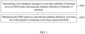
- the antenna adjusting method is applied to a terminal and includes: transmitting a first broadcast message in a case that a plurality of antennae are in an SISO mode, and acquiring radiation efficiencies of the plurality of antennae; and maintaining the SISO mode in a case that the radiation efficiency of at least one of the plurality of antennae is less than a preset threshold.
- the method further includes: switching the SISO mode to an MIMO mode in a case that the radiation efficiency of each of the plurality of antennae is greater than or equal to the preset threshold.
- the plurality of preset thresholds are in one-to-one correspondence with the radiation efficiencies of the plurality of antennae.
- the plurality of antennae include a first antenna and a second antenna.
- the step of acquiring the radiation efficiencies of the plurality of antennae includes: determining the radiation efficiency of the first antenna according to a space loss isolation between the first antenna and the second antenna, a transmitting power of the first antenna and a reflecting power of the first antenna; and determining the radiation efficiency of the second antenna according to a space loss isolation between the first antenna and the second antenna, a transmitting power of the second antenna and a reflecting power of the second antenna.
- the method further includes: in the SISO mode, transmitting a second broadcast message to an external device, where the second broadcast message includes first instruction information, and the first instruction information is used to instruct external device to switch the working mode of its own antenna to the SISO mode.
- the method further includes: in the SISO mode, transmitting a data packet to an external device, where the data packet includes second instruction information, second instruction information is used to instruct external device to switch the working mode of its own antenna to the SISO mode.
- an embodiment of the present application provides an antenna adjusting device.
- the antenna adjusting device is applied to a terminal and includes: a receiving and transmitting management module, configured to transmit a first broadcast message in a case that a plurality of antennae are in an SISO mode; a radiation efficiency acquisition module, configured to acquire radiation efficiencies of the plurality of antennae; and a mode adjusting module, configured to maintain the SISO mode in a case that the radiation efficiency of at least one of the plurality of antennae is less than a preset threshold.
- an embodiment of the present application provides a terminal.
- the terminal includes a processor, a memory, and a computer program stored in the memory and executable on the processor, where when the computer program is executed by the processor, the steps of the antenna adjusting method according to the first aspect are implemented.
- the first broadcast message is transmitted and the antenna environment where the terminal is located is acquired, that is, the radiation efficiencies of the plurality of antennae, and determination is performed based on the radiation efficiency and the preset threshold, so that the current antenna environment can be known before the terminal transmits data, and the working state of the antenna can be corrected before data transmission; therefore, the problems of data packet error and packet loss caused by the deterioration of the antenna environment are avoided.
- the first broadcast message is transmitted in the gap between two adjacent data transmissions without occupying the data transmission time, and a suitable mode for the data packet can be adjusted according to the current antenna environment, so that the transmission efficiency is improved.
- FIG. 1 is a flowchart of an antenna adjusting method according to an embodiment of the present application. As shown in FIG. 1 , the antenna adjusting method may include:
- the first broadcast message is transmitted and the antenna environment where the terminal is located is acquired, that is, the radiation efficiencies of the plurality of antennae, and determination is performed based on the radiation efficiency and the preset threshold, so that the current antenna environment can be known before the terminal transmits data, and the working state of the antenna can be corrected before data transmission; therefore, the problems of data packet error and packet loss caused by the deterioration of the antenna environment are avoided.
- the first broadcast message is transmitted in the gap between two adjacent data transmissions without occupying the data transmission time, and a suitable mode for the data packet can be adjusted according to the current antenna environment, so that the transmission efficiency is improved.
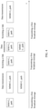
- FIG. 2 is a comparison diagram between the present application and the related art.
- the processing process on the left side is an antenna adjusting method in the related art
- the processing process on the right side is an antenna adjusting method provided by an embodiment of the present application.
- a link is detected in a data link layer, for example, data rate, bit error rate and other data are detected, and control and determination are performed based on the detected data. If the problems of packet error and packet loss are found, the physical layer controls to solve the problems of packet error and packet loss.
- the hardware link environment of the antenna is directly detected in the physical layer, and a suitable transmission mode for each data packet is adjusted when the antenna environment deteriorates, so that the link hardware environment can be monitored in real time and it is unnecessary to spend time to detect the data rate.
- the transmission mode is the working mode of the plurality of antennae of the terminal.
- FIG. 3 is a schematic diagram of data transmission in the related art.
- the Wi-Fi MIMO communication system includes C0-path and C1-path antennae.
- data is transmitted by the MIMO mode, and an acknowledge character (Acknowledge character, ACK) is transmitted by the SISO mode.
- ACK acknowledge character
- the SISO mode the first broadcast message is transmitted by a lowest-level transmission protocol, that is, the SISO mode, so that the quality stability of the link is ensured.
- FIG. 4 is a schematic diagram of a data transmission process according to an embodiment of the present application.
- the next data transmission may be performed by the SISO mode.
- the communication quality (namely, the state of the antenna) of the physical layer on the link can be detected by transmitting the first broadcast message, the transmission mode of the to-be-transmitted data packet can be adjusted according to the communication quality, so that a suitable transmission mode for the data packet can be adjusted according to the communication quality, and the transmission efficiency can be improved.
- the state of the antenna is detected by transmitting the first broadcast message, which does not occupy the data transmission time, and detection is performed every time the broadcast message is sent, so that each data packet can have a change to select a suitable transmission mode. Therefore, the problem of packet loss caused by the deterioration of the state of the antenna may be solved.
- the SISO mode is maintained if the radiation efficiency of at least one of the plurality of antennae is less than the preset threshold.
- the first broadcast message is transmitted by the SISO mode.
- the data packet is transmitted to the external device by continuously using the SISO mode.
- the antenna adjusting method further includes: switching the SISO mode to an MIMO mode in a case that the radiation efficiency of each of the plurality of antennae is greater than or equal to the preset threshold.
- the step specifically includes: continuing to transmit a first broadcast message after the previous data transmission and acquiring the radiation efficiency of the current plurality of antennae; and switching the SISO mode to the MIMO mode in a case that the radiation efficiency of each of the plurality of antennae is greater than or equal to the preset threshold.
- the first broadcast message may be transmitted in a data transmission time slot (that is, a time interval between two data transmissions), or the first broadcast message may be transmitted first before data is sent.
- FIG. 5 is a schematic diagram of another data transmission process according to an embodiment of the present application.
- the first broadcast message is transmitted by the SISO mode and the radiation efficiencies of the current plurality of antennae are acquired. If the radiation efficiency of each of the plurality of is greater than or equal to the preset threshold, the antenna mode is switched from the SISO mode to the MIMO mode before the next data packet transmission.
- the MIMO communication system includes C0-path and C1-path antennae.
- the terminal will try to use the MIMO mode to transmit data again after using the SISO mode to transmit data for a period of time. If still failed, the terminal will continue to use the SISO mode to transmit data. Or the terminal will monitor the intensity of the signal in the data transmission process to determine whether to use the MIMO mode. If failing to try to use the MIMO mode to transmit data, the terminal will continue to use the SISO mode to transmit data.
- each preset threshold corresponds to the radiation efficiency of one of the plurality of antennae.
- the preset threshold may be set based on whether packet is lost in the current antenna environment, or may be set based on whether the user experience is affected.
- the step of acquiring the radiation efficiencies of the plurality of antennae may specifically include:
- the plurality of antennae may include 2 ⁇ 2MIMO and 4 ⁇ 4MIMO.
- 2 ⁇ 2MIMO antenna For the convenience of description, the follow will use the 2 ⁇ 2MIMO antenna as an example for description.
- the radiation efficiencies of the plurality of antennae include the radiation efficiencies between any two antennae, then 2 ⁇ 2MIMO may include four radiation efficiencies, and each preset threshold corresponds to one radiation efficiency.
- FIG. 6 is a schematic diagram of a 2 ⁇ 2MIMO system according to an embodiment of the present application.
- the 2 ⁇ 2MIMO has two antennae A0 and A1, which are connected to respective matched circuits M0 and M1; and the total efficiency of a radiation unit formed by the antennae and the matched circuits is E0.
- the antenna A0 is connected to the matched circuit M0
- the total efficiency of the radiation unit formed by the antenna A0 and the matched circuit M0 is E0
- the antenna A1 is connected to the matched circuit M1
- the total efficiency of the radiation unit formed by the antenna A1 and the matched circuit M1 is E1.
- a space loss isolation from the space of the antenna A0 to the space of the antenna A1 is I.
- Reflecting coefficients of the matched circuit M0 and the matched circuit M1 are R0 and R1 respectively.
- Directional couplers C0 and C1 are arranged on each link. Specifically, the directional coupler C0 is arranged on the link corresponding to the antenna A0, the directional coupler C1 is arranged on the link corresponding to the antenna A1, and the power reflected by the matched circuit and the energy of a signal received by the link are detected.
- the receiving and transmitting management module transmits the first broadcast message
- the power of data transmitted by the C0 path namely the link corresponding to the antenna A0
- one part of the C0 path at the matched circuit M0 will reflect
- a reflecting power R0 may be acquired through the directional coupler
- one part is transmitted to the corresponding space through the antenna A0
- the power radiated to the space is P0 ⁇ E0. Since the isolation between two antennae has been determined after product design is completed, the space loss isolation I is also known.
- R1 P 0 ⁇ 1 ⁇ E 0
- R 1 P 0 ⁇ E 0 ⁇ I ⁇ E 1 .
- whether it is necessary to adjust the transmission mode of the current antenna may be determined according to the radiation efficiencies of the two antennae and the preset threshold set in the terminal.
- the MIMO mode may be switched to the SISO mode of the antenna A0 for transmission before the next data transmission.
- the MIMO mode may be switched to the SISO mode of the antenna A1 for transmission before the next data transmission.
- the antenna environment is known in advance
- the transmission mode is switched in advance when the antenna environment deteriorates, and the problem of poor user experience caused by data packet loss is avoided.
- the C0 path in each of FIG. 3 , FIG. 4 and FIG. 5 is a link where the main antenna is located. At this time, there will be an SISO time slot on the C0 path.
- the external device in a case that the working mode of the terminal changes, the external device will be informed by the following ways, so that the external device will switch the working mode to the same working mode as the terminal.
- the external device needs to be informed to switch the working mode under the following situations: first situation: in the SISO mode, a second broadcast message is transmitted to the external device, where the second broadcast message includes first instruction information, and the first instruction information is used to instruct the external device to switch the working mode of its own plurality of antennae to the SISO mode.
- the change of the working state of the terminal may be informed to the external device through the first instruction information in the second broadcast message when the second broadcast message (the message continuously transmitted after the first broadcast message is sent) is sent, and the external device switches to the same working mode as the terminal after receiving the second broadcast message, thereby facilitating the subsequent data transmission.
- the second situation in the SISO mode, a data packet is transmitted to the external device, where the data packet (which is a next data packet transmitted after the first broadcast message is transmitted) includes second instruction information, and the second instruction information is used to instruct the external device to switch the working mode of its own plurality of antennae to the SISO mode.
- Data may be directly transmitted after the terminal transmits the first broadcast message to the external device and receives the response message transmitted by the external device.
- the second instruction information may be increased in the data packet, where a packet head of the data packet may carry the second instruction information.
- the broadcast message may be ACK, and at this time, the response message of the external device may also be ACK; and the broadcast message may also be a beacon (Beacon).
- Beacon a beacon
- the external device may be a device including a plurality of antennae, such as a router, a terminal, a base station and the like.
- the broadcast message will also carry the ID of the external device, and the external device corresponding to the ID will transmitted a response message after receiving the broadcast message; and if the broadcast message is not received by the external device corresponding to the ID, the broadcast message can be discarded.
- FIG. 7 is a schematic diagram of an antenna adjusting device according to an embodiment of the present application. As shown in FIG. 7 , the antenna adjusting device includes:
- the first broadcast message is transmitted and the antenna environment where the terminal is located is acquired, that is, the radiation efficiencies of the plurality of antennae, and determination is performed based on the radiation efficiency and the preset threshold, so that the current antenna environment can be known before the terminal transmits data, and the working state of the antenna can be corrected before data transmission; therefore, the problems of data packet error and packet loss caused by the deterioration of the antenna environment are avoided.
- the first broadcast message is transmitted in the gap between two adjacent data transmissions without occupying the data transmission time, and a suitable mode for the data packet can be adjusted according to the current antenna environment, so that the transmission efficiency is improved.
- the mode adjusting module 603 is further configured to: switch the SISO mode to an MIMO mode in a case that the radiation efficiency of each of the plurality of antennae is greater than or equal to the preset threshold.
- the plurality of preset thresholds are in one-to-one correspondence with the radiation efficiencies of the plurality of antennae.
- the plurality of antennae include a first antenna and a second antenna.
- the radiation efficiency acquisition module 602 is specifically configured to: determining the radiation efficiency of the first antenna according to a space loss isolation between the first antenna and the second antenna, a transmitting power of the first antenna and a reflecting power of the first antenna; and determining the radiation efficiency of the second antenna according to a space loss isolation between the first antenna and the second antenna, a transmitting power of the second antenna and a reflecting power of the second antenna.
- R0 is a feedback coefficient of a matched circuit of the first antenna
- P0 is a transmitting power of a directional coupler of the first antenna
- R1 is a feedback coefficient of a matched circuit of the second antenna
- I is a space loss isolation
- the receiving and transmitting management module 601 is further configured to: transmit a second broadcast message to an external device in an SISO mode, where the second broadcast message is used to instruct other terminals to switch the working mode of their own antennae to the SISO mode.
- the receiving and transmitting management module 601 is further configured to: transmit a data packet to an external device in an SISO mode, where the data packet includes instruction information, and the instruction information is used to instruct the external device to switch the working mode of its own antenna to the SISO mode.
- the terminal provided by the embodiments of the present application can implement various processes implemented by the terminal in the method embodiment in FIG. 1 . To avoid repetition, details are not described herein again.
- the first broadcast message is transmitted and the antenna environment where the terminal is located is acquired, that is, the radiation efficiencies of the plurality of antennae, and determination is performed based on the radiation efficiency and the preset threshold, so that the current antenna environment can be known before the terminal transmits data, and the working state of the antenna can be corrected before data transmission; therefore, the problems of data packet error and packet loss caused by the deterioration of the antenna environment are avoided.
- the first broadcast message is transmitted in the gap between two adjacent data transmissions without occupying the data transmission time, and a suitable mode for the data packet can be adjusted according to the current antenna environment, so that the transmission efficiency is improved.
- FIG. 8 is a schematic diagram of a hardware structure of a terminal according to embodiments of the present application.
- the terminal 10 includes, but is not limited to: components such as a radio frequency unit 101, a network module 102, an audio output unit 103, an input unit 104, a sensor 105, a display unit 106, a user input unit 107, an interface unit 108, a memory 109, a processor 110, and a power supply 111.
- components such as a radio frequency unit 101, a network module 102, an audio output unit 103, an input unit 104, a sensor 105, a display unit 106, a user input unit 107, an interface unit 108, a memory 109, a processor 110, and a power supply 111.
- the terminal structure shown in FIG. 8 does not constitute a limitation to the terminal.
- the terminal may include more or fewer components than those shown in the figure, or some components may be combined, or there may be a different component arrangement.
- the terminal includes, but not limited to, a mobile phone, a tablet computer, a notebook computer, a palmtop computer, a
- the processor 110 is configured to: transmit a first broadcast message in a case that a plurality of antennae are in an SISO mode, acquire radiation efficiencies of the plurality of antennae, and maintain the SISO mode in a case that the radiation efficiency of at least one of the plurality of antennae is less than a preset threshold.
- the first broadcast message is transmitted and the antenna environment where the terminal is located is acquired, that is, the radiation efficiencies of the plurality of antennae, and determination is performed based on the radiation efficiency and the preset threshold, so that the current antenna environment can be known before the terminal transmits data, and the working state of the antenna can be corrected before data transmission; therefore, the problems of data packet error and packet loss caused by the deterioration of the antenna environment are avoided.
- the first broadcast message is transmitted in the gap between two adjacent data transmissions without occupying the data transmission time, and a suitable mode for the data packet can be adjusted according to the current antenna environment, so that the transmission efficiency is improved.
- the radio frequency unit 101 may be configured to receive and transmit information, or receive and transmit signals during a call. Specifically, the radio frequency unit 101 receives downlink data from a base station, and transmits the downlink data to the processor 110 for processing; and in addition, transmits uplink data to the base station.
- the radio frequency unit 101 includes, but is not limited to, an antenna, at least one amplifier, a transceiver, a coupler, a low noise amplifier, and a duplexer, and the like.
- the radio frequency unit 101 may further communicate with a network and another device by using a wireless communication system.
- the terminal provides wireless broadband Internet access for a user by using the network module 102, for example, helping the user transmit and receive an email, browse a web page, and access streaming media.
- the audio output unit 103 may convert audio data received by the radio frequency unit 101 or the network module 102 or stored in the memory 109 into an audio signal, and output the audio signal into sound. Moreover, the audio output unit 103 may further provide audio output related to a specific function performed by the terminal 10 (such as a call signal reception sound, a message reception sound, or the like).
- the audio output unit 103 includes a loudspeaker, a buzzer, a receiver, and the like.
- the input unit 104 is configured to receive audio or video signals.
- the input unit 104 may include a graphics processing unit (Graphics Processing Unit, GPU) 1041 and a microphone 1042.
- the graphics processing unit 1041 processes image data of a static picture or a video obtained by an image capturing apparatus (for example, a camera) in a video capturing mode or an image capturing mode.
- a processed image frame may be displayed on the display unit 106.
- the image frame processed by the graphics processing unit 1041 may be stored in the memory 109 (or another storage medium) or transmitted via the radio frequency unit 101 or the network module 102.
- the microphone 1042 may receive sound and may process such sound into audio data.
- the processed audio data may be converted, in a call mode, into a format that may be transmitted to a mobile communication base station by using the radio frequency unit 101 for output.
- the terminal 10 further includes at least one sensor 105, such as a light sensor, a motion sensor, and other sensors.
- the light sensor includes an ambient light sensor and a proximity sensor.
- the ambient light sensor may adjust luminance of the display panel 1061 based on brightness of ambient light.
- the proximity sensor may turn off the display panel 1061 and/or backlight when the terminal 10 moves to an ear.
- an accelerometer sensor can detect magnitudes of accelerations in all directions (usually three axes), can detect a magnitude and a direction of gravity in a static state, and can be applied to terminal posture recognition (such as screen switching between portrait and landscape, related games, and magnetometer posture calibration), functions related to vibration recognition (such as pedometer and tapping), and the like.
- the sensor 105 may also include a fingerprint sensor, a pressure sensor, an iris sensor, a molecular sensor, a gyroscope, a barometer, a hygrometer, a thermometer, an infrared sensor, and the like. Details are not described herein.
- the display unit 106 is configured to display information inputted by a user or information provided to a user.
- the display unit 106 may include a display panel 1061, and the display panel 1061 may be configured in a form of a liquid crystal display (Liquid Crystal Display, LCD), an organic light-emitting diode (Organic Light-Emitting Diode, OLED), or the like.
- LCD Liquid Crystal Display
- OLED Organic Light-Emitting Diode
- the user input unit 107 may be configured to receive input digit or character information and generate key signal input related to user setting and function control of the terminal.
- the user input unit 107 includes a touch panel 1071 and other input devices 1072.
- the touch panel 1071 is also referred to as a touchscreen, and may collect a touch operation performed by a user on or near the touch panel 1071 (such as an operation performed by a user on the touch panel 1071 or near the touch panel 1071 by using any proper object or accessory, such as a finger or a stylus).
- the touch panel 1071 may include two parts: a touch detection device and a touch controller.
- the touch detection device detects a touch position of a user, detects a signal brought by a touch operation, and transmits the signal to the touch controller.
- the touch controller receives touch information from the touch detection apparatus, converts the touch information into contact coordinates, sends the contact coordinates to the processor 110, and receives and executes a command from the processor 110.
- the touch panel 1071 may be implemented by various types such as a resistive type, a capacitive type, an infrared ray type or a surface acoustic wave type.
- the user input unit 107 may further include other input devices 1072.
- the other input devices 1072 may include, but are not limited to, a physical keyboard, a function key (for example, a volume control key or a switch key), a trackball, a mouse, and a joystick. Details are not described herein again.
- the touch panel 1071 may cover the display panel 1061.
- the touch panel 1071 transmits the touch operation to the processor 110 to determine a type of a touch event, and then the processor 110 provides corresponding visual output on the display panel 1061 based on the type of the touch event.
- the touch panel 1071 and the display panel 1061 are used as two separate components to implement input and output functions of the terminal in FIG. 8 , in some embodiments, the touch panel 1071 and the display panel 1061 may be integrated to implement the input and output functions of the terminal. This is not specifically limited herein.
- the interface unit 108 is an interface for connecting an external device to the terminal 10.
- the external apparatus may include a wired or wireless headset port, an external power supply (or a battery charger) port, a wired or wireless data port, a memory card port, a port for connecting an apparatus having an identification module, an audio input/output (I/O) port, a video I/O port, a headset port, and the like.
- the interface unit 108 may be configured to receive an input (for example, data information or power) from an external apparatus and transmit the received input to one or more elements in the terminal 10, or transmit data between the terminal 10 and the external apparatus.
- the memory 109 may be configured to store software programs and various data.
- the memory 109 may mainly include a program storage area and a data storage area.
- the program storage area may store an operating system, an application required for at least one function (for example, a sound playback function or an image playback function), and the like.
- the data storage area may store data (for example, audio data or an address book) or the like created based on use of the mobile phone.
- the memory 109 may include a highspeed random access memory, or may include a nonvolatile memory, for example, at least one disk storage device, a flash memory, or another volatile solid-state storage device.
- the processor 110 is a control center of the terminal, and connects all parts of the entire terminal by using various interfaces and lines. By running or executing a software program and/or a module stored in the memory 109 and invoking data stored in the memory 109, the processor performs various functions of the terminal and data processing, to perform overall monitoring on the terminal.
- the processor 110 may include one or more processing units.
- the processor 110 may be integrated with an application processor and a modem processor, where the application processor mainly processes an operating system, a user interface, an application program and the like, and the modem processor mainly processes wireless communication. It may be understood that the above-mentioned modem processor may not be integrated in the processor 110.
- the terminal 10 may further include the power supply 111 (for example, a battery) configured to supply power to various components.
- the power supply 111 may be logically connected to the processor 110 through a power management system, so as to implement functions such as managing charging, discharging, and power consumption through the power management system.
- the terminal 10 includes some function modules that are not shown, which are not elaborated here.
- the embodiment of the present application further provides a terminal, including a processor 110, a memory 109, and a computer program stored in the memory 109 and executable on the processor 110, where when the computer program is executed by the processor 110, various processes of the antenna adjusting method embodiment are implemented, and a same technical effect can be achieved. To avoid repetition, details are not described herein again.
- the embodiment of the present application further provides a computer readable storage medium.
- the computer readable storage medium stores a computer program.
- the computer program is executed by a processor, various processes of the antenna adjusting method embodiment are implemented, and a same technical effect can be achieved. To avoid repetition, details are not described herein again.
- the computer readable storage medium includes a read-only memory (Read-only Memory, ROM), a random access memory (Random Access Memory, RAM), a magnetic disk, or an optical disc.
- the method in the foregoing embodiment may be implemented by software in addition to a necessary universal hardware platform or only by hardware. In most circumstances, the former is a preferred implementation manner.
- the technical solutions of this application essentially, or the part contributing to the prior art may be implemented in a form of a software product.
- the computer software product is stored in a storage medium (for example, a ROM/RAM, a magnetic disk, or a compact disc), and includes a plurality of instructions for instructing a terminal (which may be a mobile phone, a computer, a server, an air conditioner, a network device, or the like) to perform the method described in the embodiments of this application.
Landscapes
- Engineering & Computer Science (AREA)
- Computer Networks & Wireless Communication (AREA)
- Signal Processing (AREA)
- Physics & Mathematics (AREA)
- Electromagnetism (AREA)
- Mobile Radio Communication Systems (AREA)
Applications Claiming Priority (2)
| Application Number | Priority Date | Filing Date | Title |
|---|---|---|---|
| CN201910334978.4A CN110190915B (zh) | 2019-04-24 | 2019-04-24 | 天线调节方法、装置及终端 |
| PCT/CN2020/086182 WO2020216258A1 (zh) | 2019-04-24 | 2020-04-22 | 天线调节方法、装置及终端 |
Publications (2)
| Publication Number | Publication Date |
|---|---|
| EP3961941A1 true EP3961941A1 (de) | 2022-03-02 |
| EP3961941A4 EP3961941A4 (de) | 2022-06-15 |
Family
ID=67715083
Family Applications (1)
| Application Number | Title | Priority Date | Filing Date |
|---|---|---|---|
| EP20794214.5A Pending EP3961941A4 (de) | 2019-04-24 | 2020-04-22 | Verfahren und vorrichtung zur antennenanpassung und endgerät |
Country Status (4)
| Country | Link |
|---|---|
| US (1) | US11979204B2 (de) |
| EP (1) | EP3961941A4 (de) |
| CN (1) | CN110190915B (de) |
| WO (1) | WO2020216258A1 (de) |
Families Citing this family (4)
| Publication number | Priority date | Publication date | Assignee | Title |
|---|---|---|---|---|
| CN110190915B (zh) | 2019-04-24 | 2021-01-29 | 维沃移动通信有限公司 | 天线调节方法、装置及终端 |
| US11751275B2 (en) * | 2020-02-20 | 2023-09-05 | Qualcomm Incorporated | Management of antenna switching according to a sounding reference symbol antenna switching configuration |
| CN112566086A (zh) * | 2020-12-07 | 2021-03-26 | 维沃移动通信有限公司 | 数据传输方法、装置、电子设备及可读存储介质 |
| CN120769322A (zh) * | 2024-03-29 | 2025-10-10 | 荣耀终端股份有限公司 | 天线模式的切换方法、电子设备、芯片系统及存储介质 |
Family Cites Families (13)
| Publication number | Priority date | Publication date | Assignee | Title |
|---|---|---|---|---|
| US7301924B1 (en) * | 2002-07-15 | 2007-11-27 | Cisco Technology, Inc. | Media access control for MIMO wireless network |
| US8284721B2 (en) * | 2008-06-26 | 2012-10-09 | Apple Inc. | Methods and apparatus for antenna isolation-dependent coexistence in wireless systems |
| US20110250926A1 (en) * | 2009-12-21 | 2011-10-13 | Qualcomm Incorporated | Dynamic antenna selection in a wireless device |
| US9401756B2 (en) * | 2012-05-03 | 2016-07-26 | Wistron Neweb Corporation | Method for configuring multiple antennas and related wireless communication device |
| CN103347293A (zh) * | 2013-07-11 | 2013-10-09 | 北京大学 | 一种移动通信基站系统中天线自适应节能方法 |
| CN103414507A (zh) * | 2013-07-26 | 2013-11-27 | 北京小米科技有限责任公司 | 一种移动终端及其天线的切换方法和装置 |
| DE102013110801B4 (de) * | 2013-09-30 | 2025-07-03 | Intel Corporation | Vorrichtung und Verfahren zur Bestimmung von Informationen über eine Strahlungsleistung eines Sendesignals |
| US9553640B1 (en) * | 2015-12-22 | 2017-01-24 | Microsoft Technology Licensing, Llc | Using multi-feed antennas |
| CN105656528B (zh) * | 2015-12-28 | 2019-09-24 | 联想(北京)有限公司 | 一种信息处理方法及电子设备 |
| CN109039397B (zh) * | 2018-08-01 | 2021-03-19 | 维沃移动通信有限公司 | 一种移动终端的天线电路、控制方法及装置 |
| CN109150327B (zh) * | 2018-08-28 | 2021-04-02 | 维沃移动通信有限公司 | 一种天线检测方法、天线检测装置及移动终端 |
| CN109617587B (zh) * | 2018-11-28 | 2021-09-03 | 维沃移动通信有限公司 | 天线选择方法、终端及存储介质 |
| CN110190915B (zh) * | 2019-04-24 | 2021-01-29 | 维沃移动通信有限公司 | 天线调节方法、装置及终端 |
-
2019
- 2019-04-24 CN CN201910334978.4A patent/CN110190915B/zh active Active
-
2020
- 2020-04-22 EP EP20794214.5A patent/EP3961941A4/de active Pending
- 2020-04-22 WO PCT/CN2020/086182 patent/WO2020216258A1/zh not_active Ceased
-
2021
- 2021-10-22 US US17/508,859 patent/US11979204B2/en active Active
Also Published As
| Publication number | Publication date |
|---|---|
| US11979204B2 (en) | 2024-05-07 |
| US20220045723A1 (en) | 2022-02-10 |
| WO2020216258A1 (zh) | 2020-10-29 |
| EP3961941A4 (de) | 2022-06-15 |
| CN110190915B (zh) | 2021-01-29 |
| CN110190915A (zh) | 2019-08-30 |
Similar Documents
| Publication | Publication Date | Title |
|---|---|---|
| EP3998713B1 (de) | Verfahren zur sendeantennenumschaltung und endgerätevorrichtung | |
| US11979204B2 (en) | Antenna adjusting method and device, and terminal | |
| US11973721B2 (en) | Activation control method, user equipment and network device | |
| US12231943B2 (en) | Information processing method and terminal | |
| US11936474B2 (en) | Transmission antenna switching method and terminal device | |
| CN111565078B (zh) | 频分双工模式的信道检测方法、射频电路及电子设备 | |
| EP4120720B1 (de) | Signalübertragungsverfahren, informationsanzeigeverfahren und kommunikationsvorrichtung | |
| US11909490B2 (en) | Scheduling request transmitting method, scheduling request receiving method, terminal, and network device | |
| CN110399000B (zh) | 一种移动终端及其温控方法 | |
| WO2021197149A1 (zh) | 终端能力上报、确定方法、终端及通信设备 | |
| EP3713279B1 (de) | Verfahren zur steuerung der rrm-messung einer benachbarten zelle, mobiles kommunikationsendgerät und netzseitige vorrichtung | |
| EP3817289B1 (de) | Zellenverwaltungsverfahren, endgerät und netzwerkseitige vorrichtung | |
| SG11202110815UA (en) | Ssb transmission indication method and apparatus, terminal, device, and medium | |
| US12418891B2 (en) | Feedback information transmission method and apparatus, device, and medium | |
| US12137381B2 (en) | Random access method and terminal | |
| CN110475328B (zh) | 控制方法、终端设备及网络设备 | |
| US20210204294A1 (en) | Communication method for mobile terminal and mobile terminal | |
| CN110034873B (zh) | 一种重配置方法、终端及基站 | |
| US11523442B2 (en) | Random access resource selection method and terminal device | |
| US12119936B2 (en) | Data transmission method, terminal, and network device | |
| US20210219247A1 (en) | Power headroom reporting method and terminal device | |
| WO2021139627A1 (zh) | 参数上报方法及上行调度方法、设备及介质 | |
| CN111585666A (zh) | 一种功率补偿方法和电子设备 | |
| US11570724B2 (en) | Method for PH calculation and terminal | |
| HK40065170A (en) | Scheduling request sending method, scheduling request receiving method, terminal and network device |
Legal Events
| Date | Code | Title | Description |
|---|---|---|---|
| STAA | Information on the status of an ep patent application or granted ep patent |
Free format text: STATUS: THE INTERNATIONAL PUBLICATION HAS BEEN MADE |
|
| PUAI | Public reference made under article 153(3) epc to a published international application that has entered the european phase |
Free format text: ORIGINAL CODE: 0009012 |
|
| STAA | Information on the status of an ep patent application or granted ep patent |
Free format text: STATUS: REQUEST FOR EXAMINATION WAS MADE |
|
| 17P | Request for examination filed |
Effective date: 20211122 |
|
| AK | Designated contracting states |
Kind code of ref document: A1 Designated state(s): AL AT BE BG CH CY CZ DE DK EE ES FI FR GB GR HR HU IE IS IT LI LT LU LV MC MK MT NL NO PL PT RO RS SE SI SK SM TR |
|
| A4 | Supplementary search report drawn up and despatched |
Effective date: 20220518 |
|
| RIC1 | Information provided on ipc code assigned before grant |
Ipc: H04B 7/06 20060101ALI20220512BHEP Ipc: H04B 7/08 20060101ALI20220512BHEP Ipc: H04B 7/0404 20170101ALI20220512BHEP Ipc: H04B 1/40 20150101ALI20220512BHEP Ipc: H04B 17/10 20150101AFI20220512BHEP |
|
| DAV | Request for validation of the european patent (deleted) | ||
| DAX | Request for extension of the european patent (deleted) | ||
| STAA | Information on the status of an ep patent application or granted ep patent |
Free format text: STATUS: EXAMINATION IS IN PROGRESS |
|
| 17Q | First examination report despatched |
Effective date: 20250212 |