EP3961925A1 - Élément de régulation de courant basé sur la saturation d'un circuit magnétique - Google Patents
Élément de régulation de courant basé sur la saturation d'un circuit magnétique Download PDFInfo
- Publication number
- EP3961925A1 EP3961925A1 EP21193142.3A EP21193142A EP3961925A1 EP 3961925 A1 EP3961925 A1 EP 3961925A1 EP 21193142 A EP21193142 A EP 21193142A EP 3961925 A1 EP3961925 A1 EP 3961925A1
- Authority
- EP
- European Patent Office
- Prior art keywords
- magnetic core
- current
- controlling element
- magnetic
- current controlling
- Prior art date
- Legal status (The legal status is an assumption and is not a legal conclusion. Google has not performed a legal analysis and makes no representation as to the accuracy of the status listed.)
- Pending
Links
Images



Classifications
-
- H—ELECTRICITY
- H10—SEMICONDUCTOR DEVICES; ELECTRIC SOLID-STATE DEVICES NOT OTHERWISE PROVIDED FOR
- H10N—ELECTRIC SOLID-STATE DEVICES NOT OTHERWISE PROVIDED FOR
- H10N50/00—Galvanomagnetic devices
- H10N50/10—Magnetoresistive devices
-
- H—ELECTRICITY
- H01—ELECTRIC ELEMENTS
- H01F—MAGNETS; INDUCTANCES; TRANSFORMERS; SELECTION OF MATERIALS FOR THEIR MAGNETIC PROPERTIES
- H01F3/00—Cores, Yokes, or armatures
- H01F3/10—Composite arrangements of magnetic circuits
- H01F3/14—Constrictions; Gaps, e.g. air-gaps
-
- H—ELECTRICITY
- H01—ELECTRIC ELEMENTS
- H01H—ELECTRIC SWITCHES; RELAYS; SELECTORS; EMERGENCY PROTECTIVE DEVICES
- H01H50/00—Details of electromagnetic relays
- H01H50/16—Magnetic circuit arrangements
-
- G—PHYSICS
- G01—MEASURING; TESTING
- G01R—MEASURING ELECTRIC VARIABLES; MEASURING MAGNETIC VARIABLES
- G01R15/00—Details of measuring arrangements of the types provided for in groups G01R17/00 - G01R29/00, G01R33/00 - G01R33/26 or G01R35/00
- G01R15/14—Adaptations providing voltage or current isolation, e.g. for high-voltage or high-current networks
- G01R15/18—Adaptations providing voltage or current isolation, e.g. for high-voltage or high-current networks using inductive devices, e.g. transformers
- G01R15/183—Adaptations providing voltage or current isolation, e.g. for high-voltage or high-current networks using inductive devices, e.g. transformers using transformers with a magnetic core
- G01R15/185—Adaptations providing voltage or current isolation, e.g. for high-voltage or high-current networks using inductive devices, e.g. transformers using transformers with a magnetic core with compensation or feedback windings or interacting coils, e.g. 0-flux sensors
-
- H—ELECTRICITY
- H01—ELECTRIC ELEMENTS
- H01C—RESISTORS
- H01C10/00—Adjustable resistors
- H01C10/10—Adjustable resistors adjustable by mechanical pressure or force
- H01C10/103—Adjustable resistors adjustable by mechanical pressure or force by using means responding to magnetic or electric fields, e.g. by addition of magnetisable or piezoelectric particles to the resistive material, or by an electromagnetic actuator
-
- H—ELECTRICITY
- H01—ELECTRIC ELEMENTS
- H01F—MAGNETS; INDUCTANCES; TRANSFORMERS; SELECTION OF MATERIALS FOR THEIR MAGNETIC PROPERTIES
- H01F27/00—Details of transformers or inductances, in general
- H01F27/24—Magnetic cores
- H01F27/255—Magnetic cores made from particles
-
- H—ELECTRICITY
- H01—ELECTRIC ELEMENTS
- H01H—ELECTRIC SWITCHES; RELAYS; SELECTORS; EMERGENCY PROTECTIVE DEVICES
- H01H50/00—Details of electromagnetic relays
- H01H50/16—Magnetic circuit arrangements
- H01H50/163—Details concerning air-gaps, e.g. anti-remanence, damping, anti-corrosion
-
- H—ELECTRICITY
- H01—ELECTRIC ELEMENTS
- H01H—ELECTRIC SWITCHES; RELAYS; SELECTORS; EMERGENCY PROTECTIVE DEVICES
- H01H50/00—Details of electromagnetic relays
- H01H50/44—Magnetic coils or windings
-
- H—ELECTRICITY
- H03—ELECTRONIC CIRCUITRY
- H03K—PULSE TECHNIQUE
- H03K17/00—Electronic switching or gating, i.e. not by contact-making and –breaking
- H03K17/51—Electronic switching or gating, i.e. not by contact-making and –breaking characterised by the components used
- H03K17/80—Electronic switching or gating, i.e. not by contact-making and –breaking characterised by the components used using non-linear magnetic devices; using non-linear dielectric devices
-
- H—ELECTRICITY
- H03—ELECTRONIC CIRCUITRY
- H03K—PULSE TECHNIQUE
- H03K17/00—Electronic switching or gating, i.e. not by contact-making and –breaking
- H03K17/51—Electronic switching or gating, i.e. not by contact-making and –breaking characterised by the components used
- H03K17/90—Electronic switching or gating, i.e. not by contact-making and –breaking characterised by the components used by the use, as active elements, of galvano-magnetic devices, e.g. Hall-effect devices
-
- H—ELECTRICITY
- H03—ELECTRONIC CIRCUITRY
- H03K—PULSE TECHNIQUE
- H03K17/00—Electronic switching or gating, i.e. not by contact-making and –breaking
- H03K17/94—Electronic switching or gating, i.e. not by contact-making and –breaking characterised by the way in which the control signals are generated
- H03K17/945—Proximity switches
- H03K17/95—Proximity switches using a magnetic detector
- H03K17/9515—Proximity switches using a magnetic detector using non-linear magnetic devices
Definitions
- the invention relates to a current controlling element, which comprises a first magnetic core forming a magnetic circuit, a coil, which is designed to generate a magnetic flux in the first magnetic core when it its energized, and a second magnetic core, which is arranged at a distance from the first magnetic core.
- an object of the invention is the provision of an improved current controlling element.
- a current controlling element shall be provided, which overcomes the above limitations.
- the object of the invention is solved by an arrangement as disclosed in the opening paragraph, which additionally comprises a magnetoresistive conductor arranged in a first air gap between the first magnetic core and the second magnetic core.
- the current controlling element functions as follows: When the current through the coil is increased, the magnetic flux through the first magnetic core is increased as well. At some point, the first magnetic core is saturated and an additional magnetic flux caused by an additional current through the coil flows outside the first magnetic core.
- the current controlling element is designed in a way that said additional flux is guided through the second magnetic core causing the magnetoresistive conductor being exposed to magnetic field as well. Accordingly, the resistance of the magnetoresistive conductor is changed and hence a current through the magnetoresistive conductor is changed.
- the magnetoresistive conductor in particular its active parts, e.g. its semiconductor structure
- beneficially is placed in a region of a high magnetic flux (i.e. a high concentration of flux lines).
- the point or range when the first magnetic core saturates and the magnetic field emanates into the second magnetic core is chosen in a way that the current linked to this magnetic flux corresponds to a switching threshold or switching range of the current controlling element.
- the nominal switching current of the current controlling element is at said switching threshold.
- a "nominal switching current” Inom for a current I through the coil or a “switching threshold” can be defined. Both terms can interchangeably used throughout this disclosure.
- the magnetic flux mainly exists in the first magnetic core below the nominal switching current Inom or the switching threshold, and it emanates into the second magnetic core at and above the nominal switching current Inom or the switching threshold. Hence, there is a substantial traverse magnetic field through the magnetoresistive conductor above the nominal switching current Inom or above the switching threshold influencing the resistance of the magnetoresistive conductor.
- the current controlling element can comprise a housing with a nominal switching current Inom for a current I through the coil or an information referring to the nominal switching current Inom printed on the housing.
- Such an information can be a part number or a symbol or a color associated with a particular nominal switching current Inom.
- the current controlling element is designed in a way that the current linked to this magnetic flux corresponds to a switching range of the current controlling element.
- the nominal switching current of the current controlling element is within said switching range.
- the point or range when the first magnetic core saturates can be influenced by choosing the material and the cross section of the first magnetic core in a useful way. Lower cross sections and magnetic materials with a lower saturation flux density lead to earlier saturations and thus to a lower switching point or switching range.
- the first magnetic core is designed in way that parts thereof, which saturate at the switching point or switching range, are arranged nearby the magnetoresistive conductor and the second magnetic core. Other parts of the first magnetic core, which saturate well above the switching point or switching range, are arranged at a greater distance from the magnetoresistive conductor and the second magnetic core.
- This behavior can be achieved by making the cross section of the first magnetic core smaller in a region nearby to the magnetoresistive conductor and the second magnetic core than elsewhere. Alternatively or in addition, this behavior can be achieved by using a magnetic material with a lower saturation flux density in a region nearby to the magnetoresistive conductor and the second magnetic core than elsewhere.
- a cross section of a leg or a part of the first magnetic core, which is arranged nearby the magnetoresistive conductor and the second magnetic core can be smaller than the cross section in the other legs of the first magnetic core or in other parts thereof.
- a magnetic material with a lower saturation flux density can be used for a leg or a part of the first magnetic core, which is arranged nearby the magnetoresistive conductor and the second magnetic core, and a magnetic material with a higher saturation flux density can be used in other legs or parts of the first magnetic core.
- a current controlling element with a number of beneficial characteristics is obtained.
- the disclosed current controlling element is very robust and suitable for high currents (i.e. it has a small resistance at nominal current). Hence, it qualifies well for heavy duty applications.
- the first magnetic core can form a) a closed magnetic circuit without a second air gap or b) an open magnetic circuit having at least one second air gap.
- An air gap provides the advantage, that the current through the coil, which flows when the first magnetic core saturates, and thus the switching threshold can be controlled.
- the length of the second air gap preferably is chosen in a way that the first magnetic core saturates when the nominal current is reached.
- the first magnetic core in case b) comprises a first sub part and a separate second sub part with the at least one second air gap in-between (i.e. between the first sub part and the second sub part).
- the second sub part is closer to the magnetoresistive conductor and the second magnetic core than the first sub part.
- the second sub part shall preferably saturate when the nominal current is reached, and the second sub part shall saturate after the first sub part what can be achieved by design of the length of the second air gap, design of the cross section of the first and the second sub part and/or material choice for the first and the second sub part. After the second sub part has been saturated, an additional magnetic flux is transferred into the second magnetic core.
- the cross section of the second sub part can be made smaller than the cross section of the first sub part.
- magnetic material with a lower saturation flux density can be used for the second sub part, and a magnetic material with a higher saturation flux density can be used for the first sub part.
- the first magnetic core in particular can form a magnetic circuit in the shape of a single ring or in the shape of multiple rings. If there is a first and a second sub part, the first sub part is shaped like an "U” in case of a single ring and shaped like an "E” or an "M” in case of a double ring magnetic circuit.
- the resistance of the magnetoresistive conductor increases with an increase of the magnetic flux through the magnetoresistive conductor.
- a switch-off characteristic or current-limiting characteristic can be provided, in other words, a kind of a normally closed contact or break contact.
- the resistance of the magnetoresistive conductor may also decrease with an increase of the magnetic flux through the magnetoresistive conductor.
- a switch-on characteristic can be provided, in other words a kind of a normally open contact or closing contact.
- the resistance with no magnetic field applied is usually comparably high for the latter materials.
- the change of resistance for those materials usually is in the range of two orders if a comparably strong magnetic field is applied.
- the magnetoresistive conductor contacts the first magnetic core and the second magnetic core. This configuration enables good heat transfer and keeps the magnetoresistive conductor comparably cool. If there is a second sub part, the magnetoresistive conductor in particular contacts the second sub part and the second magnetic core.
- a reluctance of the first magnetic core is at least 10 times lower than a reluctance of first magnetic core together with the second magnetic core.
- the magnetic flux is mainly kept within the first magnetic core up to the switching threshold.
- the first magnetic core and/or the second magnetic core is made of Vanadium permendur.
- Vanadium permendur is a soft ferromagnetic alloy comprising cobalt (Co), iron (Fe) and vanadium (Va) in particular having a saturation flux of more than 2 Tesla.
- the material of the first magnetic core and its cross section should be designed in a way that the magnetic flux up to the switching threshold can be handled without or just low saturation. If Vanadium permendur is chosen, the cross section of the first magnetic core can be kept small.
- the second magnetic core and its cross section should be designed in a way that the magnetic flux above the switching threshold can be handled. If Vanadium permendur is chosen, the cross section of the second magnetic core can be kept small as well.
- the first sub part is made of Vanadium permendur (which has a saturation flux of around or more than 2 Tesla) and/or the second sub part is made of a Mu-metal (which is a nickel-iron soft ferromagnetic alloy and which has a saturation flux of around 1 Tesla) or of ferrite (having a saturation flux 0.5 Tesla or less).
- the second magnetic core can be made of Vanadium permendur, too. These materials can well support the behavior of the first magnetic core that the second sub part saturates at the nominal current and well before saturation effects occur in the first sub part.
- the magnetoresistive conductor has a semiconductor-metal hybrid structure and operates according to the Extraordinary magnetoresistance effect.
- the Extraordinary magnetoresistance (EMR) is a magnetoresistance effect, which allows changes of the electrical resistance caused by the application of a magnetic field in the region of 1:10.000 and more. The effect occurs in semiconductor-metal hybrid systems when a transverse magnetic field is applied. Without a magnetic field the magnetoresistive conductor has a low-resistance. Upon application of a magnetic field the magnetoresistive conductor has a much higher electrical resistance. Accordingly, this material is suitable for the disclosed "switching" applications.
- the current controlling element comprises two control terminals with the coil switched in-between and two controlled current terminals with the magnetoresistive conductor switched in-between. In this way, a device is formed, by which a current in a first circuit including the magnetoresistive conductor is controlled by a current in a second circuit including the coil.
- the current controlling element comprises two auto current limiter terminals and a series connection of the coil and the magnetoresistive conductor switched in-between. In this way, the current in an electric circuit can be limited. Hence, the current controlling element becomes a "current limiting element" in this embodiment, e.g. a circuit breaker.
- the current controlling element has a nominal switching current Inom for a current I through the coil, wherein
- Fig. 1 shows a first example of a current controlling element 1a in schematic side view.
- the current controlling element 1a comprises a first magnetic core 2a forming a magnetic circuit, a coil 3, which is designed to generate a magnetic flux in the first magnetic core 2a when it its energized, and a second magnetic core 4a, which is arranged at a distance from the first magnetic core 2a.
- the current controlling element 1a comprises a magnetoresistive conductor 5 arranged in a first air gap 6 between the first magnetic core 2a and the second magnetic core 4a.
- the current controlling 1a element further on has two control terminals TC1, TC2 with the coil 3 switched in-between and two controlled current terminals TCI1, TCI2 with the magnetoresistive conductor 5 switched in-between. Accordingly, a voltage between the two control terminals TC1, TC2 leads to a current through the coil 3 and in turn to a magnetic flux in the first magnetic core 2a and depending on the value of the current also in the second magnetic core 4a. In this way, the resistance between the two controlled current terminals TCI1, TCI2 is influenced or controlled what is explained in more detail by use of the Figs. 8 to 10 .
- the first magnetic core 2a is designed in way that parts thereof, which saturate at the switching threshold, are arranged nearby the magnetoresistive conductor 5 and the second magnetic core 4a.
- the cross section of the lower leg of the first magnetic core 2a which is arranged nearby the magnetoresistive conductor 5 and the second magnetic core 4a, is smaller than the cross section in the other legs. Accordingly, saturation occurs earlier in the lower leg than in the other legs. Because the lower leg of the first magnetic core 2a is arranged nearby the magnetoresistive conductor 5 and the second magnetic core 4a, an additional magnetic flux reliably emanates into the second magnetic core 4a and thereby traverses the magnetoresistive conductor 5.
- a magnetic material with a lower saturation flux density can be used for the lower leg, and magnetic material with a higher saturation flux density can be use for the other legs, which leads to earlier saturation in the lower leg as well.
- Fig. 2 shows another example of a current controlling element 1b, which is quite similar to the current controlling element 1a of Fig. 1 .
- a resistor 7 is switched between the two controlled current terminals TCI1, TCI2.
- the resistor 7 provides an alternative electric path for the electric (short circuit) current so that electric energy can be dissipated in the resistor 7 when the magnetoresistive conductor 5 cuts off current.
- undesired heat up of the magnetoresistive conductor 5 can be avoided.
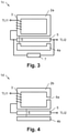
- Fig. 3 shows another example of a current controlling element 1c, which is quite similar to the current controlling element 1b of Fig. 2 .
- the current controlling element 1c comprises two auto current limiter terminals TLI1, TLI2 and a series connection of the coil 3 and the magnetoresistive conductor 5 switched in-between.
- the current in an electric circuit, which the current controlling element 1c is part of can be limited.
- the current controlling element 1c becomes a "current limiting element" in this embodiment, e.g. a circuit breaker.
- a resistor 7 may be switched in parallel with the magnetoresistive conductor 5 or not.
- Fig. 4 shows another example of a current controlling element 1d, which is similar to the current controlling element 1c of Fig. 3 .
- the second magnetic core 4b is shaped differently to the second magnetic core 4a (it is bar-shaped instead of U-shaped) and the first magnetic core 2b does not form a closed magnetic circuit without a second air gap (case a), but an open magnetic circuit having a second air gap 8a (case b).
- the second air gap 8a provides the advantage, that the current through the coil 3, which flows when the first magnetic core 2b saturates, and thus the switching threshold can be controlled.
- the length of the second air gap 8a preferably is chosen in a way that the first magnetic core 2b saturates when the nominal current is reached.
- Fig. 5 shows another example of a current controlling element 1e, which is similar to the current controlling element 1d of Fig. 4 .
- the first magnetic core 2c comprises a first sub part 9a and a separate second sub part 10 with the second air gaps 8b in-between.
- the length of the second air gaps 8b preferably is chosen in a way that the second sub part 10 saturates when the nominal current is reached. After the second sub part 10 has been saturated, an additional magnetic flux is transferred into the second magnetic core 4b. Preferably, the second sub part 10 saturates well before any saturation effects occur the first sub part 9a.
- Fig. 6 shows another example of a current controlling element 1f, which is similar to the current controlling element 1e of Fig. 5 .
- the magnetoresistive conductor 5 contacts the first magnetic core 2c and the second magnetic core 4b, in detail the second sub part 10 and the second magnetic core 4b. This configuration enables good heat transfer and keeps the magnetoresistive conductor 5 comparably cool.
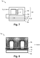
- Fig. 7 shows another example of a current controlling element 1g, which is similar to the current controlling element 1f of Fig. 6 .
- the first sub part 9b is not U-shaped, but M-shaped or E-shaped. In this way there are three areas, in which the magnetic flux traverses the magnetoresistive conductor 5, instead of two. This may contribute to vary the resistance of the magnetoresistive conductor 5 in comparison to the embodiment shown in Figs. 1 to 6 .
- Figs. 8 to 10 now illustrate the function of the current controlling element 1g.
- Fig. 8 shows the magnetic flux in the current controlling element 1g in a current range below the nominal switching current I ⁇ Inom or below the switching threshold. As is visible, the flux lines are concentrated in the first magnetic core 9b and there is no or no substantial magnetic flux in the magnetoresistive conductor 5 and in the second magnetic core 4b.
- Fig. 10 finally shows the magnetic flux in the current controlling element 1g in a current range above the nominal switching current I>Inom or above the switching threshold.
- the flux lines emanate into the magnetoresistive conductor 5 and into the second magnetic core 4b to a substantial extent.
- the magnetoresistive conductor 5 is traversed by a substantial number of flux lines.
- Figs. 8 to 10 is similar to or comparable with the function of all embodiments shown in Figs. 1 to 7 . That is why the technical teaching disclosed in the context of Figs. 8 to 10 and disclosed hereinafter is applicable to all embodiments shown in Figs. 1 to 7 .
- a reluctance of the first magnetic core 2a..2d (alone) preferably is at least 10 times lower than a reluctance of first magnetic core 2a..2d together with the second magnetic core 4a, 4b. In this way, the magnetic flux is mainly kept within the first magnetic core 2a..2d up to the nominal switching current I>Inom or up to the switching threshold.
- the magnetic flux mainly exists in the first magnetic core 2a..2d below the nominal switching current Inom, and it emanates into the second magnetic core 4a, 4b at or above the nominal switching current Inom. It should be noted that there is no "binary" swap of the magnetic flux into the second magnetic core 4a, 4b in the sense of all or nothing, but the change is continuous, but also steep depending on the design as illustrated in Figs. 1 to 10 .
- the desired behavior can be achieved by choosing appropriate cross sections for the first sub part 9b and the second sub part 10.
- the cross section of the second sub part 10 is small compared to the cross section of the first sub part 9b.
- the second sub part 10 saturates well before any saturation effects occur the first sub part 9a.
- the first magnetic core 2a..2d and/or the second magnetic core 4a, 4b is/are made of Vanadium permendur.
- the material of the first magnetic core 2a..2d and its cross section should be designed in a way that the magnetic flux up to the switching threshold can be handled. If Vanadium permendur is chosen, the cross section of the first magnetic core 2a..2d can be kept small.
- the second magnetic core 4a, 4b and its cross section should be designed in a way that the magnetic flux above the switching threshold can be handled. If Vanadium permendur is chosen, the cross section of the second magnetic core 4a, 4b can be kept small as well.
- the first sub part 9a, 9b is made of Vanadium permendur and/or the second sub part 10 is made of a Mu-metal, which is a nickel-iron soft ferromagnetic alloy.
- the second magnetic core 4a, 4b preferably can be made of Vanadium permendur, too. The way of this material choice supports the behavior of the first magnetic core 2c, 2d that the second sub part 10 saturates at the nominal current Inom and that the second sub part 10 saturates well before any saturation effects occur the first sub part 9a, 9b.
- the current controlling element 1a..1f can comprise a housing (not shown in the Figs.) with a nominal switching current Inom for a current I through the coil 3 or an information referring to the nominal switching current Inom printed on the housing.
- a nominal switching current Inom for a current I through the coil 3
- an information referring to the nominal switching current Inom printed on the housing can be a part number or a symbol or a color associated with a particular nominal switching current Inom.
- the magnetoresistive conductor 5 has a semiconductor-metal hybrid structure and operates according to the Extraordinary magnetoresistance effect.
- the Extraordinary magnetoresistance (EMR) is a magnetoresistance effect, which allows changes of the electrical resistance caused the application of a magnetic field in the region of 1:10.000 and more. The effect occurs in semiconductor-metal hybrid systems when a transverse magnetic field is applied. Without a magnetic field the magnetoresistive conductor 5 has a low-resistance. Upon application of a magnetic field the magnetoresistive conductor 5 has a much higher electrical resistance. Accordingly, this material is well suited for "switching" applications. In particular, a switch-off characteristic or current-limiting characteristic can be provided, in other words a kind of a normally closed contact or break contact.
- the resistance of the magnetoresistive conductor 5 may also decrease with an increase of the magnetic flux through the magnetoresistive conductor 5. In that way, a switch-on characteristic can be provided, in other words a kind of a normally open contact or closing contact.
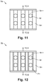
- Fig. 11 shows a first exemplary structure of a magnetoresistive conductor 5a in cross sectional view.
- the magnetoresistive conductor 5a comprises alternating negative doted layers N+ and highly negative doted layers N++, wherein metal parts M are embedded in the highly negative doted layers N++.
- resistor 7 may be part of any one of the embodiments depicted in Figs. 1 to 7 .
- the current control function and the current limiting function is not linked to a particular design of the magnetic circuits, but it depends if the coil 3 and the magnetoresistive conductor 5 are switched in series or not.
Landscapes
- Physics & Mathematics (AREA)
- Engineering & Computer Science (AREA)
- Power Engineering (AREA)
- Electromagnetism (AREA)
- Nonlinear Science (AREA)
- Chemical & Material Sciences (AREA)
- Composite Materials (AREA)
- General Physics & Mathematics (AREA)
- Microelectronics & Electronic Packaging (AREA)
- Coils Or Transformers For Communication (AREA)
- Emergency Protection Circuit Devices (AREA)
Applications Claiming Priority (1)
| Application Number | Priority Date | Filing Date | Title |
|---|---|---|---|
| GB2013521.6A GB2598365A (en) | 2020-08-28 | 2020-08-28 | Current controlling element based on saturation of a magnetic circuit |
Publications (1)
| Publication Number | Publication Date |
|---|---|
| EP3961925A1 true EP3961925A1 (fr) | 2022-03-02 |
Family
ID=72749794
Family Applications (1)
| Application Number | Title | Priority Date | Filing Date |
|---|---|---|---|
| EP21193142.3A Pending EP3961925A1 (fr) | 2020-08-28 | 2021-08-25 | Élément de régulation de courant basé sur la saturation d'un circuit magnétique |
Country Status (4)
| Country | Link |
|---|---|
| US (1) | US12518898B2 (fr) |
| EP (1) | EP3961925A1 (fr) |
| CN (1) | CN114121554B (fr) |
| GB (1) | GB2598365A (fr) |
Cited By (1)
| Publication number | Priority date | Publication date | Assignee | Title |
|---|---|---|---|---|
| IT202200005345A1 (it) * | 2022-03-18 | 2023-09-18 | Microtest S P A | Un rele’ con generazione del campo magnetico attraverso un pcb |
Families Citing this family (1)
| Publication number | Priority date | Publication date | Assignee | Title |
|---|---|---|---|---|
| DE102023131800A1 (de) | 2023-11-15 | 2025-05-15 | Eaton Intelligent Power Limited | Einheit und Verfahren zum Vorladen einer DC-Last mit einer Eingangskapazität |
Citations (3)
| Publication number | Priority date | Publication date | Assignee | Title |
|---|---|---|---|---|
| US5564194A (en) * | 1994-05-31 | 1996-10-15 | Sony Corporation | Geomagnetic direction sensor |
| US6710587B1 (en) * | 2002-10-11 | 2004-03-23 | Solidone Usa Corporation | Low magnitude current sensor using unbalanced flux line detection |
| EP2442117A1 (fr) * | 2009-06-12 | 2012-04-18 | Alps Green Devices Co., Ltd. | Capteur de courant à équilibre magnétique |
Family Cites Families (19)
| Publication number | Priority date | Publication date | Assignee | Title |
|---|---|---|---|---|
| CH455046A (de) * | 1966-01-05 | 1968-04-30 | Siemens Ag | Kontaktloses elektromagnetisches Relais mit galvanischer Trennung von Steuer- und Nutzstromkreis |
| US5461308A (en) * | 1993-12-30 | 1995-10-24 | At&T Ipm Corp. | Magnetoresistive current sensor having high sensitivity |
| US5930095A (en) * | 1996-08-16 | 1999-07-27 | Back Joo | Superconducting current limiting device by introducing the air gap in the magnetic core |
| US5889373A (en) * | 1996-12-30 | 1999-03-30 | General Electric Company | Fluorescent lamp ballast with current feedback using a dual-function magnetic device |
| WO2003107017A1 (fr) * | 2002-06-01 | 2003-12-24 | 株式会社エルポート | Detecteur de courant de type a pont magnetique, procede de detection de courant de type a pont magnetique et pont magnetique destine a etre utilise avec ce detecteur ainsi que procede de detection |
| US20040032315A1 (en) * | 2002-08-19 | 2004-02-19 | Lewis Illingworth | Variable inductor responsive to AC current level |
| JP5143765B2 (ja) * | 2009-02-16 | 2013-02-13 | 株式会社東海理化電機製作所 | 電流センサ |
| US9081307B2 (en) * | 2010-07-09 | 2015-07-14 | Asml Netherlands B.V. | Variable reluctance device, stage apparatus, lithographic apparatus and device manufacturing method |
| CN101908413B (zh) * | 2010-07-27 | 2012-10-03 | 上海诺雅克电气有限公司 | 给电子装置供电用电流互感器 |
| CN201975250U (zh) * | 2011-01-13 | 2011-09-14 | 上海诺雅克电气有限公司 | 电子式保护用供电电流互感器 |
| CN102800471A (zh) * | 2011-05-26 | 2012-11-28 | 北京人民电器厂有限公司 | 速饱和电流互感器 |
| GB201115005D0 (en) * | 2011-08-31 | 2011-10-12 | Univ Cardiff | Fault current limiter |
| CN102427004B (zh) * | 2011-11-28 | 2014-12-24 | 常熟开关制造有限公司(原常熟开关厂) | 一种断路器用脱扣器 |
| DE102012209782B4 (de) * | 2012-06-12 | 2017-10-19 | Bender Gmbh & Co. Kg | Verfahren und Vorrichtung zur allstromsensitiven Strommessung |
| CN104052332A (zh) * | 2013-03-12 | 2014-09-17 | 洪日勇 | 蓄磁变电器 |
| CN104715899A (zh) * | 2013-12-12 | 2015-06-17 | 台达电子企业管理(上海)有限公司 | 三相电抗器 |
| KR102524352B1 (ko) * | 2015-07-16 | 2023-04-21 | 고쿠리츠 다이가쿠 호진 도호쿠 다이가쿠 | 자기 저항 효과 소자 및 자기 메모리 |
| FR3050069B1 (fr) * | 2016-04-08 | 2018-05-11 | Valeo Siemens Eautomotive France Sas | Composant magnetique, circuit electrique resonant, convertisseur electrique et systeme electrique |
| CN106057395A (zh) * | 2016-08-16 | 2016-10-26 | 福州大学 | 一种具有永磁偏磁的磁性元件组合体及其实现方法 |
-
2020
- 2020-08-28 GB GB2013521.6A patent/GB2598365A/en active Pending
-
2021
- 2021-08-19 CN CN202110953221.0A patent/CN114121554B/zh active Active
- 2021-08-24 US US17/409,890 patent/US12518898B2/en active Active
- 2021-08-25 EP EP21193142.3A patent/EP3961925A1/fr active Pending
Patent Citations (3)
| Publication number | Priority date | Publication date | Assignee | Title |
|---|---|---|---|---|
| US5564194A (en) * | 1994-05-31 | 1996-10-15 | Sony Corporation | Geomagnetic direction sensor |
| US6710587B1 (en) * | 2002-10-11 | 2004-03-23 | Solidone Usa Corporation | Low magnitude current sensor using unbalanced flux line detection |
| EP2442117A1 (fr) * | 2009-06-12 | 2012-04-18 | Alps Green Devices Co., Ltd. | Capteur de courant à équilibre magnétique |
Cited By (2)
| Publication number | Priority date | Publication date | Assignee | Title |
|---|---|---|---|---|
| IT202200005345A1 (it) * | 2022-03-18 | 2023-09-18 | Microtest S P A | Un rele’ con generazione del campo magnetico attraverso un pcb |
| WO2023175447A1 (fr) * | 2022-03-18 | 2023-09-21 | Microtest S.P.A. | Relais à génération de champ magnétique à travers une carte de circuit imprimé |
Also Published As
| Publication number | Publication date |
|---|---|
| US12518898B2 (en) | 2026-01-06 |
| GB202013521D0 (en) | 2020-10-14 |
| US20220068527A1 (en) | 2022-03-03 |
| GB2598365A (en) | 2022-03-02 |
| CN114121554A (zh) | 2022-03-01 |
| CN114121554B (zh) | 2025-03-25 |
Similar Documents
| Publication | Publication Date | Title |
|---|---|---|
| US4070641A (en) | Current limiting circuit breaker | |
| EP3961925A1 (fr) | Élément de régulation de courant basé sur la saturation d'un circuit magnétique | |
| CN116682701A (zh) | 触点装置和电磁继电器 | |
| NL8002470A (nl) | Laagspanningstransformatorrelais. | |
| US20240290533A1 (en) | Improved passive device, arrangement and electric circuit for limiting or reducing a current rise | |
| US9355803B2 (en) | Actuator with thermomagnetic shunt, especially for triggering a circuit breaker | |
| US3009998A (en) | Relay comprising sealed-in contacts | |
| CN110867348B (zh) | 一种高抗短路的继电器 | |
| US1164257A (en) | Circuit-interrupting device. | |
| US3437885A (en) | Electromagnet | |
| JP6760085B2 (ja) | 限流器及びこれを備える共振型限流回路 | |
| US10311932B2 (en) | Magnetic memory device | |
| US4672343A (en) | Circuit protector | |
| JP7127545B2 (ja) | 電磁アクチュエータ | |
| CN110797237B (zh) | 电磁致动器和包括该致动器的电气开关单元 | |
| JP2990225B2 (ja) | リードスイッチ | |
| US3559123A (en) | Nonpolarized magnetic reed switch | |
| JP2019047690A (ja) | 直流遮断器 | |
| JPWO2024184953A5 (fr) | ||
| JP6825369B2 (ja) | 共振型限流回路 | |
| KR101457363B1 (ko) | 전자기 구동 유니트 및 전기기계적 스위칭 장치 | |
| JPS59169023A (ja) | サ−キツトブレ−カ | |
| JPS587723A (ja) | 電気開閉器 | |
| JPH02266827A (ja) | 限流装置 | |
| JPH03291822A (ja) | 電流遮断器 |
Legal Events
| Date | Code | Title | Description |
|---|---|---|---|
| PUAI | Public reference made under article 153(3) epc to a published international application that has entered the european phase |
Free format text: ORIGINAL CODE: 0009012 |
|
| STAA | Information on the status of an ep patent application or granted ep patent |
Free format text: STATUS: THE APPLICATION HAS BEEN PUBLISHED |
|
| AK | Designated contracting states |
Kind code of ref document: A1 Designated state(s): AL AT BE BG CH CY CZ DE DK EE ES FI FR GB GR HR HU IE IS IT LI LT LU LV MC MK MT NL NO PL PT RO RS SE SI SK SM TR |
|
| STAA | Information on the status of an ep patent application or granted ep patent |
Free format text: STATUS: REQUEST FOR EXAMINATION WAS MADE |
|
| 17P | Request for examination filed |
Effective date: 20220819 |
|
| RBV | Designated contracting states (corrected) |
Designated state(s): AL AT BE BG CH CY CZ DE DK EE ES FI FR GB GR HR HU IE IS IT LI LT LU LV MC MK MT NL NO PL PT RO RS SE SI SK SM TR |
|
| P01 | Opt-out of the competence of the unified patent court (upc) registered |
Effective date: 20230521 |
|
| STAA | Information on the status of an ep patent application or granted ep patent |
Free format text: STATUS: EXAMINATION IS IN PROGRESS |
|
| 17Q | First examination report despatched |
Effective date: 20260311 |