EP3961789A1 - Heat-blocking material composition, heat-blocking material, and method for manufacturing same - Google Patents
Heat-blocking material composition, heat-blocking material, and method for manufacturing same Download PDFInfo
- Publication number
- EP3961789A1 EP3961789A1 EP20783064.7A EP20783064A EP3961789A1 EP 3961789 A1 EP3961789 A1 EP 3961789A1 EP 20783064 A EP20783064 A EP 20783064A EP 3961789 A1 EP3961789 A1 EP 3961789A1
- Authority
- EP
- European Patent Office
- Prior art keywords
- heat insulating
- insulating material
- sheet
- fiber
- mass
- Prior art date
- Legal status (The legal status is an assumption and is not a legal conclusion. Google has not performed a legal analysis and makes no representation as to the accuracy of the status listed.)
- Withdrawn
Links
- 239000000203 mixture Substances 0.000 title claims abstract description 28
- 238000000034 method Methods 0.000 title claims description 29
- 238000004519 manufacturing process Methods 0.000 title claims description 13
- 239000000463 material Substances 0.000 title description 19
- VYPSYNLAJGMNEJ-UHFFFAOYSA-N Silicium dioxide Chemical compound O=[Si]=O VYPSYNLAJGMNEJ-UHFFFAOYSA-N 0.000 claims abstract description 131
- 239000011810 insulating material Substances 0.000 claims abstract description 70
- 239000002245 particle Substances 0.000 claims abstract description 57
- 229920002678 cellulose Polymers 0.000 claims abstract description 29
- 239000001913 cellulose Substances 0.000 claims abstract description 29
- 210000001724 microfibril Anatomy 0.000 claims abstract description 28
- 239000002131 composite material Substances 0.000 claims abstract description 18
- 239000000835 fiber Substances 0.000 claims description 111
- 210000004027 cell Anatomy 0.000 claims description 44
- XLYOFNOQVPJJNP-UHFFFAOYSA-N water Substances O XLYOFNOQVPJJNP-UHFFFAOYSA-N 0.000 claims description 30
- 229920003043 Cellulose fiber Polymers 0.000 claims description 26
- 239000002994 raw material Substances 0.000 claims description 11
- RNFJDJUURJAICM-UHFFFAOYSA-N 2,2,4,4,6,6-hexaphenoxy-1,3,5-triaza-2$l^{5},4$l^{5},6$l^{5}-triphosphacyclohexa-1,3,5-triene Chemical compound N=1P(OC=2C=CC=CC=2)(OC=2C=CC=CC=2)=NP(OC=2C=CC=CC=2)(OC=2C=CC=CC=2)=NP=1(OC=1C=CC=CC=1)OC1=CC=CC=C1 RNFJDJUURJAICM-UHFFFAOYSA-N 0.000 claims description 9
- 239000003063 flame retardant Substances 0.000 claims description 9
- 238000001035 drying Methods 0.000 claims description 8
- 239000002002 slurry Substances 0.000 claims description 8
- 239000012784 inorganic fiber Substances 0.000 claims description 6
- 239000004642 Polyimide Substances 0.000 claims description 4
- 229920006231 aramid fiber Polymers 0.000 claims description 4
- 238000002156 mixing Methods 0.000 claims description 4
- 239000004417 polycarbonate Substances 0.000 claims description 4
- 229920000515 polycarbonate Polymers 0.000 claims description 4
- 229920001721 polyimide Polymers 0.000 claims description 4
- 239000000377 silicon dioxide Substances 0.000 description 38
- 230000002265 prevention Effects 0.000 description 18
- 239000007787 solid Substances 0.000 description 18
- 238000002474 experimental method Methods 0.000 description 10
- 239000010410 layer Substances 0.000 description 10
- 230000000052 comparative effect Effects 0.000 description 9
- 239000006185 dispersion Substances 0.000 description 7
- 150000001875 compounds Chemical class 0.000 description 6
- 238000001816 cooling Methods 0.000 description 6
- 230000008569 process Effects 0.000 description 6
- 238000006243 chemical reaction Methods 0.000 description 5
- 230000000694 effects Effects 0.000 description 5
- 239000010419 fine particle Substances 0.000 description 5
- 239000011148 porous material Substances 0.000 description 5
- 239000000843 powder Substances 0.000 description 5
- 239000000126 substance Substances 0.000 description 5
- 239000004964 aerogel Substances 0.000 description 4
- 230000007423 decrease Effects 0.000 description 4
- 229910021485 fumed silica Inorganic materials 0.000 description 4
- 230000001771 impaired effect Effects 0.000 description 4
- 238000012360 testing method Methods 0.000 description 4
- 230000003247 decreasing effect Effects 0.000 description 3
- 239000000428 dust Substances 0.000 description 3
- 229910052500 inorganic mineral Inorganic materials 0.000 description 3
- 239000011707 mineral Substances 0.000 description 3
- 238000001556 precipitation Methods 0.000 description 3
- 229920001131 Pulp (paper) Polymers 0.000 description 2
- MCMNRKCIXSYSNV-UHFFFAOYSA-N Zirconium dioxide Chemical compound O=[Zr]=O MCMNRKCIXSYSNV-UHFFFAOYSA-N 0.000 description 2
- XAGFODPZIPBFFR-UHFFFAOYSA-N aluminium Chemical compound [Al] XAGFODPZIPBFFR-UHFFFAOYSA-N 0.000 description 2
- 229910052782 aluminium Inorganic materials 0.000 description 2
- PNEYBMLMFCGWSK-UHFFFAOYSA-N aluminium oxide Inorganic materials [O-2].[O-2].[O-2].[Al+3].[Al+3] PNEYBMLMFCGWSK-UHFFFAOYSA-N 0.000 description 2
- 239000003795 chemical substances by application Substances 0.000 description 2
- 230000006835 compression Effects 0.000 description 2
- 238000007906 compression Methods 0.000 description 2
- 238000011156 evaluation Methods 0.000 description 2
- 238000010438 heat treatment Methods 0.000 description 2
- 230000006872 improvement Effects 0.000 description 2
- 239000007791 liquid phase Substances 0.000 description 2
- 230000014759 maintenance of location Effects 0.000 description 2
- 238000001000 micrograph Methods 0.000 description 2
- 230000035699 permeability Effects 0.000 description 2
- 239000004033 plastic Substances 0.000 description 2
- 229920003023 plastic Polymers 0.000 description 2
- 239000010409 thin film Substances 0.000 description 2
- OHVLMTFVQDZYHP-UHFFFAOYSA-N 1-(2,4,6,7-tetrahydrotriazolo[4,5-c]pyridin-5-yl)-2-[4-[2-[[3-(trifluoromethoxy)phenyl]methylamino]pyrimidin-5-yl]piperazin-1-yl]ethanone Chemical compound N1N=NC=2CN(CCC=21)C(CN1CCN(CC1)C=1C=NC(=NC=1)NCC1=CC(=CC=C1)OC(F)(F)F)=O OHVLMTFVQDZYHP-UHFFFAOYSA-N 0.000 description 1
- KZEVSDGEBAJOTK-UHFFFAOYSA-N 1-(2,4,6,7-tetrahydrotriazolo[4,5-c]pyridin-5-yl)-2-[5-[2-[[3-(trifluoromethoxy)phenyl]methylamino]pyrimidin-5-yl]-1,3,4-oxadiazol-2-yl]ethanone Chemical compound N1N=NC=2CN(CCC=21)C(CC=1OC(=NN=1)C=1C=NC(=NC=1)NCC1=CC(=CC=C1)OC(F)(F)F)=O KZEVSDGEBAJOTK-UHFFFAOYSA-N 0.000 description 1
- LDXJRKWFNNFDSA-UHFFFAOYSA-N 2-(2,4,6,7-tetrahydrotriazolo[4,5-c]pyridin-5-yl)-1-[4-[2-[[3-(trifluoromethoxy)phenyl]methylamino]pyrimidin-5-yl]piperazin-1-yl]ethanone Chemical compound C1CN(CC2=NNN=C21)CC(=O)N3CCN(CC3)C4=CN=C(N=C4)NCC5=CC(=CC=C5)OC(F)(F)F LDXJRKWFNNFDSA-UHFFFAOYSA-N 0.000 description 1
- JQMFQLVAJGZSQS-UHFFFAOYSA-N 2-[4-[2-(2,3-dihydro-1H-inden-2-ylamino)pyrimidin-5-yl]piperazin-1-yl]-N-(2-oxo-3H-1,3-benzoxazol-6-yl)acetamide Chemical compound C1C(CC2=CC=CC=C12)NC1=NC=C(C=N1)N1CCN(CC1)CC(=O)NC1=CC2=C(NC(O2)=O)C=C1 JQMFQLVAJGZSQS-UHFFFAOYSA-N 0.000 description 1
- IHCCLXNEEPMSIO-UHFFFAOYSA-N 2-[4-[2-(2,3-dihydro-1H-inden-2-ylamino)pyrimidin-5-yl]piperidin-1-yl]-1-(2,4,6,7-tetrahydrotriazolo[4,5-c]pyridin-5-yl)ethanone Chemical compound C1C(CC2=CC=CC=C12)NC1=NC=C(C=N1)C1CCN(CC1)CC(=O)N1CC2=C(CC1)NN=N2 IHCCLXNEEPMSIO-UHFFFAOYSA-N 0.000 description 1
- JVKRKMWZYMKVTQ-UHFFFAOYSA-N 2-[4-[2-(2,3-dihydro-1H-inden-2-ylamino)pyrimidin-5-yl]pyrazol-1-yl]-N-(2-oxo-3H-1,3-benzoxazol-6-yl)acetamide Chemical compound C1C(CC2=CC=CC=C12)NC1=NC=C(C=N1)C=1C=NN(C=1)CC(=O)NC1=CC2=C(NC(O2)=O)C=C1 JVKRKMWZYMKVTQ-UHFFFAOYSA-N 0.000 description 1
- VXZBYIWNGKSFOJ-UHFFFAOYSA-N 2-[4-[5-(2,3-dihydro-1H-inden-2-ylamino)pyrazin-2-yl]pyrazol-1-yl]-1-(2,4,6,7-tetrahydrotriazolo[4,5-c]pyridin-5-yl)ethanone Chemical compound C1C(CC2=CC=CC=C12)NC=1N=CC(=NC=1)C=1C=NN(C=1)CC(=O)N1CC2=C(CC1)NN=N2 VXZBYIWNGKSFOJ-UHFFFAOYSA-N 0.000 description 1
- YLZOPXRUQYQQID-UHFFFAOYSA-N 3-(2,4,6,7-tetrahydrotriazolo[4,5-c]pyridin-5-yl)-1-[4-[2-[[3-(trifluoromethoxy)phenyl]methylamino]pyrimidin-5-yl]piperazin-1-yl]propan-1-one Chemical compound N1N=NC=2CN(CCC=21)CCC(=O)N1CCN(CC1)C=1C=NC(=NC=1)NCC1=CC(=CC=C1)OC(F)(F)F YLZOPXRUQYQQID-UHFFFAOYSA-N 0.000 description 1
- WTFUTSCZYYCBAY-SXBRIOAWSA-N 6-[(E)-C-[[4-[2-(2,3-dihydro-1H-inden-2-ylamino)pyrimidin-5-yl]piperazin-1-yl]methyl]-N-hydroxycarbonimidoyl]-3H-1,3-benzoxazol-2-one Chemical compound C1C(CC2=CC=CC=C12)NC1=NC=C(C=N1)N1CCN(CC1)C/C(=N/O)/C1=CC2=C(NC(O2)=O)C=C1 WTFUTSCZYYCBAY-SXBRIOAWSA-N 0.000 description 1
- DFGKGUXTPFWHIX-UHFFFAOYSA-N 6-[2-[4-[2-(2,3-dihydro-1H-inden-2-ylamino)pyrimidin-5-yl]piperazin-1-yl]acetyl]-3H-1,3-benzoxazol-2-one Chemical compound C1C(CC2=CC=CC=C12)NC1=NC=C(C=N1)N1CCN(CC1)CC(=O)C1=CC2=C(NC(O2)=O)C=C1 DFGKGUXTPFWHIX-UHFFFAOYSA-N 0.000 description 1
- DEXFNLNNUZKHNO-UHFFFAOYSA-N 6-[3-[4-[2-(2,3-dihydro-1H-inden-2-ylamino)pyrimidin-5-yl]piperidin-1-yl]-3-oxopropyl]-3H-1,3-benzoxazol-2-one Chemical compound C1C(CC2=CC=CC=C12)NC1=NC=C(C=N1)C1CCN(CC1)C(CCC1=CC2=C(NC(O2)=O)C=C1)=O DEXFNLNNUZKHNO-UHFFFAOYSA-N 0.000 description 1
- HRPVXLWXLXDGHG-UHFFFAOYSA-N Acrylamide Chemical compound NC(=O)C=C HRPVXLWXLXDGHG-UHFFFAOYSA-N 0.000 description 1
- ZOXJGFHDIHLPTG-UHFFFAOYSA-N Boron Chemical compound [B] ZOXJGFHDIHLPTG-UHFFFAOYSA-N 0.000 description 1
- WKBOTKDWSSQWDR-UHFFFAOYSA-N Bromine atom Chemical compound [Br] WKBOTKDWSSQWDR-UHFFFAOYSA-N 0.000 description 1
- ZAMOUSCENKQFHK-UHFFFAOYSA-N Chlorine atom Chemical compound [Cl] ZAMOUSCENKQFHK-UHFFFAOYSA-N 0.000 description 1
- 229920001410 Microfiber Polymers 0.000 description 1
- MKYBYDHXWVHEJW-UHFFFAOYSA-N N-[1-oxo-1-(2,4,6,7-tetrahydrotriazolo[4,5-c]pyridin-5-yl)propan-2-yl]-2-[[3-(trifluoromethoxy)phenyl]methylamino]pyrimidine-5-carboxamide Chemical compound O=C(C(C)NC(=O)C=1C=NC(=NC=1)NCC1=CC(=CC=C1)OC(F)(F)F)N1CC2=C(CC1)NN=N2 MKYBYDHXWVHEJW-UHFFFAOYSA-N 0.000 description 1
- NIPNSKYNPDTRPC-UHFFFAOYSA-N N-[2-oxo-2-(2,4,6,7-tetrahydrotriazolo[4,5-c]pyridin-5-yl)ethyl]-2-[[3-(trifluoromethoxy)phenyl]methylamino]pyrimidine-5-carboxamide Chemical compound O=C(CNC(=O)C=1C=NC(=NC=1)NCC1=CC(=CC=C1)OC(F)(F)F)N1CC2=C(CC1)NN=N2 NIPNSKYNPDTRPC-UHFFFAOYSA-N 0.000 description 1
- AFCARXCZXQIEQB-UHFFFAOYSA-N N-[3-oxo-3-(2,4,6,7-tetrahydrotriazolo[4,5-c]pyridin-5-yl)propyl]-2-[[3-(trifluoromethoxy)phenyl]methylamino]pyrimidine-5-carboxamide Chemical compound O=C(CCNC(=O)C=1C=NC(=NC=1)NCC1=CC(=CC=C1)OC(F)(F)F)N1CC2=C(CC1)NN=N2 AFCARXCZXQIEQB-UHFFFAOYSA-N 0.000 description 1
- 229910019142 PO4 Inorganic materials 0.000 description 1
- OAICVXFJPJFONN-UHFFFAOYSA-N Phosphorus Chemical compound [P] OAICVXFJPJFONN-UHFFFAOYSA-N 0.000 description 1
- 229920003171 Poly (ethylene oxide) Polymers 0.000 description 1
- 239000004113 Sepiolite Substances 0.000 description 1
- 239000004115 Sodium Silicate Substances 0.000 description 1
- 238000005411 Van der Waals force Methods 0.000 description 1
- 125000000129 anionic group Chemical group 0.000 description 1
- 239000007864 aqueous solution Substances 0.000 description 1
- 239000004760 aramid Substances 0.000 description 1
- 230000015572 biosynthetic process Effects 0.000 description 1
- 230000000903 blocking effect Effects 0.000 description 1
- 229910052796 boron Inorganic materials 0.000 description 1
- 150000001642 boronic acid derivatives Chemical class 0.000 description 1
- GDTBXPJZTBHREO-UHFFFAOYSA-N bromine Substances BrBr GDTBXPJZTBHREO-UHFFFAOYSA-N 0.000 description 1
- 229910052794 bromium Inorganic materials 0.000 description 1
- 125000002091 cationic group Chemical group 0.000 description 1
- 239000000460 chlorine Substances 0.000 description 1
- 229910052801 chlorine Inorganic materials 0.000 description 1
- 239000011247 coating layer Substances 0.000 description 1
- 238000002485 combustion reaction Methods 0.000 description 1
- 238000013329 compounding Methods 0.000 description 1
- 238000007796 conventional method Methods 0.000 description 1
- 239000002826 coolant Substances 0.000 description 1
- BXKDSDJJOVIHMX-UHFFFAOYSA-N edrophonium chloride Chemical compound [Cl-].CC[N+](C)(C)C1=CC=CC(O)=C1 BXKDSDJJOVIHMX-UHFFFAOYSA-N 0.000 description 1
- 230000005611 electricity Effects 0.000 description 1
- 238000005516 engineering process Methods 0.000 description 1
- 238000011049 filling Methods 0.000 description 1
- 238000001914 filtration Methods 0.000 description 1
- 239000008394 flocculating agent Substances 0.000 description 1
- 239000000446 fuel Substances 0.000 description 1
- 125000000524 functional group Chemical group 0.000 description 1
- 239000003365 glass fiber Substances 0.000 description 1
- 230000005484 gravity Effects 0.000 description 1
- 230000017525 heat dissipation Effects 0.000 description 1
- 230000001939 inductive effect Effects 0.000 description 1
- 230000002401 inhibitory effect Effects 0.000 description 1
- 239000010954 inorganic particle Substances 0.000 description 1
- 239000007788 liquid Substances 0.000 description 1
- 238000011068 loading method Methods 0.000 description 1
- 239000003658 microfiber Substances 0.000 description 1
- 239000011490 mineral wool Substances 0.000 description 1
- 239000002105 nanoparticle Substances 0.000 description 1
- 230000003287 optical effect Effects 0.000 description 1
- 238000000879 optical micrograph Methods 0.000 description 1
- 230000035515 penetration Effects 0.000 description 1
- 239000003208 petroleum Substances 0.000 description 1
- 235000021317 phosphate Nutrition 0.000 description 1
- 150000003013 phosphoric acid derivatives Chemical class 0.000 description 1
- 239000011574 phosphorus Substances 0.000 description 1
- 229910052698 phosphorus Inorganic materials 0.000 description 1
- 229920001296 polysiloxane Polymers 0.000 description 1
- 238000002360 preparation method Methods 0.000 description 1
- 238000012545 processing Methods 0.000 description 1
- 238000011084 recovery Methods 0.000 description 1
- 230000009467 reduction Effects 0.000 description 1
- 239000004627 regenerated cellulose Substances 0.000 description 1
- 238000001878 scanning electron micrograph Methods 0.000 description 1
- 229910052624 sepiolite Inorganic materials 0.000 description 1
- 235000019355 sepiolite Nutrition 0.000 description 1
- 238000007873 sieving Methods 0.000 description 1
- HBMJWWWQQXIZIP-UHFFFAOYSA-N silicon carbide Chemical compound [Si+]#[C-] HBMJWWWQQXIZIP-UHFFFAOYSA-N 0.000 description 1
- 229910010271 silicon carbide Inorganic materials 0.000 description 1
- NTHWMYGWWRZVTN-UHFFFAOYSA-N sodium silicate Chemical compound [Na+].[Na+].[O-][Si]([O-])=O NTHWMYGWWRZVTN-UHFFFAOYSA-N 0.000 description 1
- 229910052911 sodium silicate Inorganic materials 0.000 description 1
- 239000000243 solution Substances 0.000 description 1
- 238000001179 sorption measurement Methods 0.000 description 1
- 230000003068 static effect Effects 0.000 description 1
- 230000001629 suppression Effects 0.000 description 1
- 230000002194 synthesizing effect Effects 0.000 description 1
- 229920002994 synthetic fiber Polymers 0.000 description 1
- 229920001187 thermosetting polymer Polymers 0.000 description 1
- 238000012546 transfer Methods 0.000 description 1
- 230000000007 visual effect Effects 0.000 description 1
- 239000010456 wollastonite Substances 0.000 description 1
- 229910052882 wollastonite Inorganic materials 0.000 description 1
Images

Classifications
-
- F—MECHANICAL ENGINEERING; LIGHTING; HEATING; WEAPONS; BLASTING
- F16—ENGINEERING ELEMENTS AND UNITS; GENERAL MEASURES FOR PRODUCING AND MAINTAINING EFFECTIVE FUNCTIONING OF MACHINES OR INSTALLATIONS; THERMAL INSULATION IN GENERAL
- F16L—PIPES; JOINTS OR FITTINGS FOR PIPES; SUPPORTS FOR PIPES, CABLES OR PROTECTIVE TUBING; MEANS FOR THERMAL INSULATION IN GENERAL
- F16L59/00—Thermal insulation in general
- F16L59/02—Shape or form of insulating materials, with or without coverings integral with the insulating materials
-
- D—TEXTILES; PAPER
- D21—PAPER-MAKING; PRODUCTION OF CELLULOSE
- D21H—PULP COMPOSITIONS; PREPARATION THEREOF NOT COVERED BY SUBCLASSES D21C OR D21D; IMPREGNATING OR COATING OF PAPER; TREATMENT OF FINISHED PAPER NOT COVERED BY CLASS B31 OR SUBCLASS D21G; PAPER NOT OTHERWISE PROVIDED FOR
- D21H11/00—Pulp or paper, comprising cellulose or lignocellulose fibres of natural origin only
- D21H11/16—Pulp or paper, comprising cellulose or lignocellulose fibres of natural origin only modified by a particular after-treatment
- D21H11/18—Highly hydrated, swollen or fibrillatable fibres
-
- D—TEXTILES; PAPER
- D21—PAPER-MAKING; PRODUCTION OF CELLULOSE
- D21H—PULP COMPOSITIONS; PREPARATION THEREOF NOT COVERED BY SUBCLASSES D21C OR D21D; IMPREGNATING OR COATING OF PAPER; TREATMENT OF FINISHED PAPER NOT COVERED BY CLASS B31 OR SUBCLASS D21G; PAPER NOT OTHERWISE PROVIDED FOR
- D21H13/00—Pulp or paper, comprising synthetic cellulose or non-cellulose fibres or web-forming material
- D21H13/10—Organic non-cellulose fibres
- D21H13/20—Organic non-cellulose fibres from macromolecular compounds obtained otherwise than by reactions only involving carbon-to-carbon unsaturated bonds
- D21H13/24—Polyesters
-
- D—TEXTILES; PAPER
- D21—PAPER-MAKING; PRODUCTION OF CELLULOSE
- D21H—PULP COMPOSITIONS; PREPARATION THEREOF NOT COVERED BY SUBCLASSES D21C OR D21D; IMPREGNATING OR COATING OF PAPER; TREATMENT OF FINISHED PAPER NOT COVERED BY CLASS B31 OR SUBCLASS D21G; PAPER NOT OTHERWISE PROVIDED FOR
- D21H13/00—Pulp or paper, comprising synthetic cellulose or non-cellulose fibres or web-forming material
- D21H13/10—Organic non-cellulose fibres
- D21H13/20—Organic non-cellulose fibres from macromolecular compounds obtained otherwise than by reactions only involving carbon-to-carbon unsaturated bonds
- D21H13/26—Polyamides; Polyimides
-
- D—TEXTILES; PAPER
- D21—PAPER-MAKING; PRODUCTION OF CELLULOSE
- D21H—PULP COMPOSITIONS; PREPARATION THEREOF NOT COVERED BY SUBCLASSES D21C OR D21D; IMPREGNATING OR COATING OF PAPER; TREATMENT OF FINISHED PAPER NOT COVERED BY CLASS B31 OR SUBCLASS D21G; PAPER NOT OTHERWISE PROVIDED FOR
- D21H13/00—Pulp or paper, comprising synthetic cellulose or non-cellulose fibres or web-forming material
- D21H13/36—Inorganic fibres or flakes
- D21H13/38—Inorganic fibres or flakes siliceous
-
- D—TEXTILES; PAPER
- D21—PAPER-MAKING; PRODUCTION OF CELLULOSE
- D21H—PULP COMPOSITIONS; PREPARATION THEREOF NOT COVERED BY SUBCLASSES D21C OR D21D; IMPREGNATING OR COATING OF PAPER; TREATMENT OF FINISHED PAPER NOT COVERED BY CLASS B31 OR SUBCLASS D21G; PAPER NOT OTHERWISE PROVIDED FOR
- D21H17/00—Non-fibrous material added to the pulp, characterised by its constitution; Paper-impregnating material characterised by its constitution
- D21H17/63—Inorganic compounds
- D21H17/67—Water-insoluble compounds, e.g. fillers, pigments
- D21H17/68—Water-insoluble compounds, e.g. fillers, pigments siliceous, e.g. clays
-
- D—TEXTILES; PAPER
- D21—PAPER-MAKING; PRODUCTION OF CELLULOSE
- D21H—PULP COMPOSITIONS; PREPARATION THEREOF NOT COVERED BY SUBCLASSES D21C OR D21D; IMPREGNATING OR COATING OF PAPER; TREATMENT OF FINISHED PAPER NOT COVERED BY CLASS B31 OR SUBCLASS D21G; PAPER NOT OTHERWISE PROVIDED FOR
- D21H17/00—Non-fibrous material added to the pulp, characterised by its constitution; Paper-impregnating material characterised by its constitution
- D21H17/71—Mixtures of material ; Pulp or paper comprising several different materials not incorporated by special processes
- D21H17/74—Mixtures of material ; Pulp or paper comprising several different materials not incorporated by special processes of organic and inorganic material
-
- D—TEXTILES; PAPER
- D21—PAPER-MAKING; PRODUCTION OF CELLULOSE
- D21H—PULP COMPOSITIONS; PREPARATION THEREOF NOT COVERED BY SUBCLASSES D21C OR D21D; IMPREGNATING OR COATING OF PAPER; TREATMENT OF FINISHED PAPER NOT COVERED BY CLASS B31 OR SUBCLASS D21G; PAPER NOT OTHERWISE PROVIDED FOR
- D21H21/00—Non-fibrous material added to the pulp, characterised by its function, form or properties; Paper-impregnating or coating material, characterised by its function, form or properties
- D21H21/14—Non-fibrous material added to the pulp, characterised by its function, form or properties; Paper-impregnating or coating material, characterised by its function, form or properties characterised by function or properties in or on the paper
- D21H21/34—Ignifugeants
-
- D—TEXTILES; PAPER
- D21—PAPER-MAKING; PRODUCTION OF CELLULOSE
- D21H—PULP COMPOSITIONS; PREPARATION THEREOF NOT COVERED BY SUBCLASSES D21C OR D21D; IMPREGNATING OR COATING OF PAPER; TREATMENT OF FINISHED PAPER NOT COVERED BY CLASS B31 OR SUBCLASS D21G; PAPER NOT OTHERWISE PROVIDED FOR
- D21H21/00—Non-fibrous material added to the pulp, characterised by its function, form or properties; Paper-impregnating or coating material, characterised by its function, form or properties
- D21H21/50—Non-fibrous material added to the pulp, characterised by its function, form or properties; Paper-impregnating or coating material, characterised by its function, form or properties characterised by form
- D21H21/52—Additives of definite length or shape
-
- D—TEXTILES; PAPER
- D21—PAPER-MAKING; PRODUCTION OF CELLULOSE
- D21H—PULP COMPOSITIONS; PREPARATION THEREOF NOT COVERED BY SUBCLASSES D21C OR D21D; IMPREGNATING OR COATING OF PAPER; TREATMENT OF FINISHED PAPER NOT COVERED BY CLASS B31 OR SUBCLASS D21G; PAPER NOT OTHERWISE PROVIDED FOR
- D21H27/00—Special paper not otherwise provided for, e.g. made by multi-step processes
-
- F—MECHANICAL ENGINEERING; LIGHTING; HEATING; WEAPONS; BLASTING
- F16—ENGINEERING ELEMENTS AND UNITS; GENERAL MEASURES FOR PRODUCING AND MAINTAINING EFFECTIVE FUNCTIONING OF MACHINES OR INSTALLATIONS; THERMAL INSULATION IN GENERAL
- F16L—PIPES; JOINTS OR FITTINGS FOR PIPES; SUPPORTS FOR PIPES, CABLES OR PROTECTIVE TUBING; MEANS FOR THERMAL INSULATION IN GENERAL
- F16L59/00—Thermal insulation in general
- F16L59/02—Shape or form of insulating materials, with or without coverings integral with the insulating materials
- F16L59/028—Composition or method of fixing a thermally insulating material
-
- H—ELECTRICITY
- H01—ELECTRIC ELEMENTS
- H01M—PROCESSES OR MEANS, e.g. BATTERIES, FOR THE DIRECT CONVERSION OF CHEMICAL ENERGY INTO ELECTRICAL ENERGY
- H01M10/00—Secondary cells; Manufacture thereof
- H01M10/60—Heating or cooling; Temperature control
- H01M10/65—Means for temperature control structurally associated with the cells
- H01M10/653—Means for temperature control structurally associated with the cells characterised by electrically insulating or thermally conductive materials
-
- H—ELECTRICITY
- H01—ELECTRIC ELEMENTS
- H01M—PROCESSES OR MEANS, e.g. BATTERIES, FOR THE DIRECT CONVERSION OF CHEMICAL ENERGY INTO ELECTRICAL ENERGY
- H01M10/00—Secondary cells; Manufacture thereof
- H01M10/60—Heating or cooling; Temperature control
- H01M10/65—Means for temperature control structurally associated with the cells
- H01M10/658—Means for temperature control structurally associated with the cells by thermal insulation or shielding
-
- H—ELECTRICITY
- H01—ELECTRIC ELEMENTS
- H01M—PROCESSES OR MEANS, e.g. BATTERIES, FOR THE DIRECT CONVERSION OF CHEMICAL ENERGY INTO ELECTRICAL ENERGY
- H01M50/00—Constructional details or processes of manufacture of the non-active parts of electrochemical cells other than fuel cells, e.g. hybrid cells
- H01M50/20—Mountings; Secondary casings or frames; Racks, modules or packs; Suspension devices; Shock absorbers; Transport or carrying devices; Holders
- H01M50/204—Racks, modules or packs for multiple batteries or multiple cells
-
- H—ELECTRICITY
- H01—ELECTRIC ELEMENTS
- H01M—PROCESSES OR MEANS, e.g. BATTERIES, FOR THE DIRECT CONVERSION OF CHEMICAL ENERGY INTO ELECTRICAL ENERGY
- H01M50/00—Constructional details or processes of manufacture of the non-active parts of electrochemical cells other than fuel cells, e.g. hybrid cells
- H01M50/30—Arrangements for facilitating escape of gases
- H01M50/383—Flame arresting or ignition-preventing means
-
- H—ELECTRICITY
- H01—ELECTRIC ELEMENTS
- H01M—PROCESSES OR MEANS, e.g. BATTERIES, FOR THE DIRECT CONVERSION OF CHEMICAL ENERGY INTO ELECTRICAL ENERGY
- H01M10/00—Secondary cells; Manufacture thereof
- H01M10/60—Heating or cooling; Temperature control
- H01M10/62—Heating or cooling; Temperature control specially adapted for specific applications
- H01M10/625—Vehicles
-
- Y—GENERAL TAGGING OF NEW TECHNOLOGICAL DEVELOPMENTS; GENERAL TAGGING OF CROSS-SECTIONAL TECHNOLOGIES SPANNING OVER SEVERAL SECTIONS OF THE IPC; TECHNICAL SUBJECTS COVERED BY FORMER USPC CROSS-REFERENCE ART COLLECTIONS [XRACs] AND DIGESTS
- Y02—TECHNOLOGIES OR APPLICATIONS FOR MITIGATION OR ADAPTATION AGAINST CLIMATE CHANGE
- Y02E—REDUCTION OF GREENHOUSE GAS [GHG] EMISSIONS, RELATED TO ENERGY GENERATION, TRANSMISSION OR DISTRIBUTION
- Y02E60/00—Enabling technologies; Technologies with a potential or indirect contribution to GHG emissions mitigation
- Y02E60/10—Energy storage using batteries
-
- Y—GENERAL TAGGING OF NEW TECHNOLOGICAL DEVELOPMENTS; GENERAL TAGGING OF CROSS-SECTIONAL TECHNOLOGIES SPANNING OVER SEVERAL SECTIONS OF THE IPC; TECHNICAL SUBJECTS COVERED BY FORMER USPC CROSS-REFERENCE ART COLLECTIONS [XRACs] AND DIGESTS
- Y02—TECHNOLOGIES OR APPLICATIONS FOR MITIGATION OR ADAPTATION AGAINST CLIMATE CHANGE
- Y02E—REDUCTION OF GREENHOUSE GAS [GHG] EMISSIONS, RELATED TO ENERGY GENERATION, TRANSMISSION OR DISTRIBUTION
- Y02E60/00—Enabling technologies; Technologies with a potential or indirect contribution to GHG emissions mitigation
- Y02E60/30—Hydrogen technology
- Y02E60/50—Fuel cells
Definitions
- the present invention relates to a heat insulating material composition and a heat insulating material that can be manufactured using the composition.
- heat insulating materials In order to suppress heat dissipation energy from the viewpoint of energy saving, demand for heat insulating materials has grown more and more in recent years.
- the heat insulating materials have received attention not only in use applications such as conventional houses, pipes, blast furnaces and electric furnaces but also from the viewpoint of heat retention of, for example, internal combustion engines and fuel cells, and heat insulating materials applicable to various shapes not limited to formed bodies are required.
- Patent Literature 1 As a technique to suppress this chain reaction of thermal runaway, a structure in which a thermal runaway prevention wall made of a heat insulating plastic is provided between adjacent secondary batteries to prevent thermal runaway from inducing thermal runaway of another secondary battery is described in Patent Literature 1.
- the thermal runaway prevention wall of Patent Literature 1 has complicated unique constitution because a secondary battery and a heat conducting tube are integrally formed, and moreover, fire spread to the plastic prevention wall itself is not taken into consideration.
- Patent Literature 2 a thermally expandable or thermosetting thermal runaway prevention sheet using a mineral-based powder or flame retardant is described.
- thermal management ability for a secondary battery cell has been regarded as performance necessary for improving cruising range, and a material satisfying both the improvement in thermal management ability and the aforesaid prevention of thermal runaway is desired.
- the thermal runaway prevention sheet described in Patent Literature 2 has a thermal conductivity of about 0.1 W/(m ⁇ K) at room temperature and does not meet the requirements.
- Patent Literature 3 and Patent Literature 4 it is disclosed that it is effective to use, as materials having a low thermal conductivity, such bulky fine particles containing fine pores as listed in these patent literatures.
- Patent Literature 3 a heat insulating sheet using an aerogel silica particle containing countless pores of several nm and a fiber is described, and this sheet is considered to have excellent heat insulating properties and excellent water resistance.
- Patent Literature 4 a porous heat insulating material in which fumed silica or fumed alumina, each being a fine particle having a fine porous structure, and an inorganic fiber are combined is described, and this heat insulating material exhibits an extremely low thermal conductivity and heat resistance from room temperature up to 600°C.
- the manufacturing cost of the aerogel that is said to have a porosity of 90% or more is high, and it is known that the aerogel greatly contracts when the temperature becomes 500°C or higher, so that when this technique is applied between cells, there is a problem with the shape retention ability at the time of thermal runaway.
- the fumed silica and the fumed alumina are excellent in heat resistance, but because of fine particles, they easily fly and are difficult to be formed. On this account, there is a problem also with formability, and there is a problem also with handling properties such as easy occurrence of dust fall.
- Patent Literature 5 As analogous material composition, a nonwoven sheet composed of inorganic particles and fine cellulose fibers and having heat resistance and high strength is described in Patent Literature 5. However, use as a separator is taken into consideration for this nonwoven sheet, and the sheet has air permeability and liquid permeability, so that there is a problem with heat insulating properties and flame shielding performance.
- Patent Literature 6 a heat insulating material using a fiber body filled with a compression formed body of nanoparticles is described.
- the thickness of the heat insulating material described is at least 1 mm or more, and in order to ensure strength, coating layers need to be further provided on both surfaces.
- fumed silica and an aerogel described in Patent Literature 6 exhibit volume recovery behavior called spring back when forming is carried out by compression, so that it is difficult to control the thickness.
- heat insulating materials cannot have excellent heat insulating properties and heat resistance together with performance capable of forming a material with thin shape, light mass, and sufficient strength and flexibility. On this account, a novel material that meets these requirements at the same time is desired.
- a heat insulating material composition comprising a composite of an amorphous silica particle manufactured by a wet process (also referred to as a "wet silica particle” in the present specification) and a microfibrillated cellulose fiber (also referred to as a "cellulose microfibril” in the present specification). That is to say, according to the embodiments of the present invention, the following aspects can be provided.
- an excellent heat insulating property can be provided.
- the heat insulating material composition according to a first embodiment of the present invention comprises a composite composed of amorphous silica particles manufactured by a wet process (hereinafter, wet silica particles) and cellulose microfibrils.
- wet silica particles have a higher bulk specific gravity as compared with bulky porous fine particles typified by fumed silica, are excellent in handling properties, and form a composite in water, so that scattering and spouting of a powder during the process are suppressed.
- the "wet silica” or the “wet silica particle” mentioned in the present specification refers to a particle of amorphous silica manufactured by a method for synthetically manufacturing an amorphous silica substance in a liquid phase (that is, wet process).
- a method for synthetically manufacturing an amorphous silica substance in a liquid phase that is, wet process.
- the precipitation method refers to, for example, a method in which an aqueous solution of sodium silicate is neutralized to precipitate silica, and the silica is take by filtering and dried.
- the amorphous silica manufactured by such a wet process is a particle (preferably fine particle) containing fine pores, and it gives a fine porous structure to the heat insulating material composition.
- Water contained in the wet silica improves heat resistance of the heat insulating material composition and plays a role of suppressing van der Waals force acting on particles.
- the water content is preferably 5 mass% or more and 15 mass% or less based on the mass of the whole wet silica. When the water content is 5 mass% or more, adhesion properties due to static electricity acting on particles do not become too high, and therefore, good handling properties may be shown. On the other hand, a water content of 15 mass% or less is preferable because the thermal conductivity does not become too high.
- the wet silica particles are heated up to 200°C by a thermogravimetric analyzer (TGA), and a water content W is calculated using a mass X before heating and a mass decrease X 1 . That is to say, the mass decrease X 1 is regarded as an amount of water.
- Water content W mass % X 1 / X ⁇ 100
- the average particle diameter of the wet silica is in the range of 1 ⁇ m to 50 ⁇ m.
- the average particle diameter may be measured as a 50% integrated particle diameter D 50 using a laser diffraction particle size measuring device ("Model LS-230" manufactured by Beckman Coulter, Inc.).
- An average particle diameter of less than 1 ⁇ m is undesirable because the wet silica particles may not sufficiently come into contact with cellulose microfibrils, and a porous structure necessary for the composite after inclusion to show heat insulating properties may not be formed, so that the heat insulating properties are deteriorated.
- the average particle diameter is more than 50 ⁇ m, the composite formed becomes coarse, so that strength of the heat insulating material may not be obtained.
- the bulk density (specifically bulk density measured by tap method according to ISO 787-11) of the wet silica is not particularly limited, but from the viewpoints of improvement in fluidity and suppression of spouting, the bulk density is preferably 50 g/L or more. When the bulk density is 50 g/L or more, an effect of facilitating control of handling properties is obtained.
- cellulose microfibril or "microfibrillated cellulose fiber” mentioned in the present specification means a microfiber obtained by treating a cellulose fiber having a high crystallinity with a high-pressure homogenizer or a grinder, etc. and thereby highly fibrillating the fiber.
- the cellulose microfibril has an extremely small fiber diameter as compared with a usual cellulose fiber, and on this account, it has a high specific surface area, and a larger number of hydrogen-bonding functional groups derived from cellulose molecules are exposed, so that the adsorption power is extremely increased.
- this cellulose microfibril interacts with the wet silica particle to exhibit good adsorptivity, and the cellulose microfibril may strongly include the wet silica particle while maintaining fine pores of the particle and may prepare a composite that favorably functions as a heat insulating material composition.
- cellulose microfibril may be evaluated using, for example, a measuring device L&W Fiber Tester Plus (manufactured by ABB AB).
- L&W Fiber Tester Plus manufactured by ABB AB
- cellulose microfibril or “microfibrillated cellulose fiber” is defined as a substance which satisfies the following conditions:
- the fiber diameter of the cellulose microfibril is, for example, 10 ⁇ m or less, and may be preferably 1 nm to 5 ⁇ m.
- the fiber length of the cellulose microfibril is not particularly limited as long as the heat insulating properties and dispersibility are not impaired.
- the mixing ratio between the wet silica particles and the microfibrillated cellulose fibers depends on the particle diameters of the wet silica particles used, the fiber lengths of the microfibrillated cellulose fibers used, etc., so that it is not particularly limited as long as the heat insulating properties are not impaired, but the amount of the microfibrillated cellulose fibers is preferably about 5 to 50 parts by mass, in terms of solid content, based on 100 parts by mass of the wet silica particles.
- the method for manufacturing the heat insulating material composition according to the embodiment of the present invention is, for example, a method including dispersing amorphous wet silica and cellulose microfibrils in water and adding a flocculant to obtain a composite dispersion.
- the composite dispersion obtained by this manufacturing method may be used as a solid after dried, and may be used as a powder among the solids.
- an arbitrary compound known in the relevant technical field may be used, and for example, an ionic flocculant (cationic flocculant, anionic flocculant, nonionic flocculant, amphoteric flocculant, or the like) may be used.
- the flocculants include phosphates, borates, ionic acrylamide, and polyethylene oxide.
- the heat insulating material is obtained by compounding, as a raw material, the already-described heat insulating material composition containing a composite.
- the heat insulating material may be a layer (heat insulating layer) obtained by using the already-described heat insulating material composition as a raw material and filling a space with the heat insulating material composition utilizing fluidity of the composition.
- the heat insulating material may be obtained by a sheet forming method.
- the heat insulating material preferably further comprises a base fiber in addition to the heat insulating material composition.
- a base fiber is preferably one or more fibers selected from the group consisting of a PET fiber, a cellulose fiber, an aramid fiber, a polyimide fiber, a polycarbonate fiber, and an inorganic fiber from the viewpoint of heat resistance.
- a base fiber having been subjected to flame-retardant treatment may be used. These fibers have a role of imparting tensile strength and flexibility to the heat insulating material.
- the cellulose fibers include wood pulp, non-wood pulp, and regenerated cellulose, but an arbitrary fiber may be used.
- Typical examples of the inorganic fibers include a silica fiber that is an artificial fiber excellent in heat resistance, an alumina-silica fiber, a glass fiber, a zirconia fiber, a silicon carbide fiber, rockwool manufactured using a mineral as a raw material, and wollastonite and sepiolite that are natural minerals, and one or a plurality of these fibers may be used according to the needs.
- the average fiber length and the average fiber diameter of the base fibers or the microfibrillated cellulose fibers are each an average value of diameters of 100 fibers confirmed by scanning electron microscope (SEM) observation.
- the average fiber length and the average fiber diameter sometimes vary depending on the quality of the material used, but they are not particularly limited as long as the heat insulating properties and the formability of the heat insulating material are not impaired.
- the average fiber diameter of the base fibers is preferably 1 to 50 ⁇ m, and more preferably 5 to 30 ⁇ m.
- the content of the base fibers is preferably 300 parts by mass or less based on 100 parts by mass of the composite composed of the wet silica particles and the microfibrillated cellulose fibers (solids), but it is not particularly limited to this as long as the heat insulating properties and the formability are not impaired.
- the amount in part(s) by mass of the composite composed of the wet silica particles and the microfibrillated cellulose fibers (solids) may be calculated from the total of the amount in part(s) by mass of the wet silica particles and the amount in part(s) by mass of the microfibrillated cellulose fibers (solids).
- the content of the base fibers is 300 parts by mass or less, the contact area between the base fibers decreases, and the heat insulating material shows heat insulating properties.
- the content of the base fibers is preferably 1 part by mass or more based on 100 parts by mass of the composite composed of the wet silica particles and the microfibrillated cellulose fibers.
- the method for manufacturing the heat insulating material in the present invention is not particularly limited, as previously stated, but when the heat insulating material is applied to a secondary battery cell described later, forming into a thin sheet by a sheet forming method is preferable from the viewpoints of reduction of surplus space and weight saving.
- the method for manufacturing the heat insulating material using such a sheet forming method preferably comprises a step of mixing the aforesaid heat insulating material composition and base fibers to obtain a slurry, a step of subjecting the slurry to sheet forming by a papermaking screen to obtain a raw material sheet, and a step of drying the raw material sheet to obtain a sheet-like heat insulating material.
- the "raw material sheet” mentioned herein refers to a sheet-like intermediate (containing a large amount of water) before drying, which is obtained by subjecting the raw material to sheet forming.
- a yankee dryer may be used.
- the thermal conductivity of the heat insulating material is 0.07 W/(m ⁇ K) or less at 23°C, the heat insulating material shows effective heat insulating properties even if it has a thin shape, so that such a thermal conductivity is preferable.
- Flame-retardant treatment (flame proofing) of a heat insulating material surface may be carried out.
- flame-retardant treatment agents include a bromine-based compound, a chlorine-based compound, a phosphorus-based compound, a boron-based compound, and a silicone-based compound, but the flame-retardant treatment agent is not limited to them as long as it contributes to flame retardance.
- the heat insulating sheet in the embodiment is obtained by processing the already-described heat insulating material into a sheet.
- the heat insulating material may be used as it is, but it may be processed into a heat insulating sheet that has been enhanced in flame retardance by using the already-described flame-retardant fibers (flameproofed fibers or inorganic fibers) as the base fibers or subjecting the surface to flame-retardant treatment or flameproofing to improve flame resistance and heat resistance.
- the heat insulating sheet By arranging the heat insulating sheet on the periphery of each cell in a battery structure having a plurality of secondary battery cells, for example, between the cells or around the cells, excellent heat insulating properties and heat resistance may be imparted to the battery structure.
- a battery structure 1 of Figure 1 has a plurality of secondary battery cells 2 and a fire spread prevention heat insulating layer 4 between the secondary battery cells.
- the fire spread prevention heat insulating layer 4 includes a heat insulating sheet 3.
- the heat insulating sheet 3 As the heat insulating sheet 3, the heat insulating sheet according to the already-described embodiment may be used, and owing to its excellent heat insulating properties, the heat insulating sheet has functions of inhibiting transfer of heat generated in each secondary battery cell 2 to the adjacent cell, suppressing thermal runaway attributable to use of a plurality of cells, and suppressing occurrence of a chain reaction of thermal runaway by heat resistance and heat insulating properties even if thermal runaway occurs.
- a battery structure 1 of Figure 2 further has a cooling system 5 equipped with a pipe through which water or a cooling medium flows, in addition to a plurality of secondary battery cells 2 and a fire spread prevention heat insulating layer 4 (including heat insulating sheet 3) between the secondary battery cells, the cells and the layer being the same as those in Figure 1 .
- the fire spread prevention heat insulating layer 4 is also made to surround the circumference of the secondary battery cell 2.
- the circumference of each secondary battery cell 2 is thermally insulated, and therefore, the heat insulating sheet 3 not only suppresses thermal runaway but also makes cooling by the cooling system 5 more effective, so that the thermal management ability for the secondary battery cell 2 is improved.
- the secondary battery cell 2 can be thermally protected from heat generated outside the battery structure 1, and as a result, heat resistance of the whole battery structure 1 is improved.
- a space 6 is provided between the fire spread prevention heat insulating layer 4 surrounding the circumference of the secondary battery cell 2 and a housing 7, and it contributes to heat blocking.
- the housing 7 refers to a housing for encasing, for example, a plurality of secondary battery cells 2 and a fire spread prevention heat insulating layer 4 (including heat insulating sheet 3) between the secondary battery cells.
- the space 6 does not need to be provided if cooling by the cooling system 5 is sufficiently effective.
- heat insulating sheet is not limited to the above secondary batteries, and the sheet may be used also for, for example, flameproofing materials or heat insulating materials of buildings.
- wet silica particles those having been controlled in the average particle diameter by synthesizing the particles by a precipitation method and classifying them with a sieving machine and having been controlled in the water content by changing the drying time were used.
- the average particle diameter was measured as a 50% integrated particle diameter D 50 defined by a laser diffraction particle size measuring device ("Model LS-230" manufactured by Beckman Coulter, Inc.).
- the water content was measured as a mass decrease ratio at the time of 105°C using a differential thermogravimetric analyzer TG-DTA 2000SR (trade name, Bruker AXS GmbH).
- Tensile strength Using a Tensilon universal testing machine (manufactured by A&D Company, Ltd.), a tensile strength was measured at a tension rate of 10 mm/min and a distance between chucks of 200 mm.
- the sheet was bent with a curvature radius of 10 mm in such a manner that the inside of the sheet made an angle of 120 degrees about the center of the sheet as a fulcrum, and when cracks did not occur on the surface of the sheet upon visual observation and the sheet returned to its original shape, the flexibility was evaluated as circle (good), and when the sheet did not satisfy the conditions, the flexibility was evaluated as X-mark (NG).
- Dry silica particles (D1) average particle diameter 0.20 ⁇ m, water content 0.9 mass%
- Heat insulating sheets were prepared in the same manner as in Experimental Example 1, except that the base fibers were changed to silica fibers, and thermal conductivity, tensile strength and flexibility were evaluated in the same manner.
- Base fibers silica fibers (average fiber diameter 20 ⁇ m)
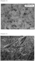
- a micrograph of Figure 3 was obtained through optical microscope observation, and a micrograph of Figure 4 was obtained through electron microscope observation. From Figure 3 , it can be seen that the base fibers that look like translucent lines running vertically and horizontally are covered with a white cotton-like porous substance. From Figure 4 , it can be seen that the porous substance is a composite in which the wet silica particles are included with a fiber substance that is obviously thin as compared with the base fibers (in Figure 4 , the base fibers look like thick pillars running from top right to left bottom), namely cellulose microfibrils.
- Fire spread prevention performance One test piece (length 100 mm, width 100 mm, thickness 1.0 mm) prepared from the resulting heat insulating sheet and one aluminum plate (length 100 mm, width 100 mm, thickness 1.0 mm) imitating an exterior material of a battery cell were prepared, and the test piece was screwed to the aluminum plate at the four corners to prepare a specimen.
- the specimen was heated from the test piece side with a burner flame at 900 to 1000°C for 10 minutes, and a case where even by the heating, the unheated surface temperature of the specimen was lower than 200°C, there was no penetration into the unheated surface, and there was no flaming was regarded as circle (good), and a case where any of these conditions was not satisfied was regarded as X-mark (NG), and thus, fire spread prevention performance to suppress a chain reaction of thermal runaway was evaluated.
- NG X-mark
- a heat insulating material composition using amorphous wet silica particles with excellent handling properties and having excellent heat insulating properties can be provided.
- a thin heat insulating sheet can also be easily provided by a sheet forming method. Since the heat insulating sheet has heat resistance, heat insulating properties and flexibility that are higher than before, it is applicable to various shapes, and therefore, it may impart excellent heat insulating properties and heat resistance not only to battery structures but also to buildings, pipes, etc.
- excellent heat insulating properties and heat resistance may be imparted to a battery structure having a plurality of secondary battery cells.
Landscapes
- Chemical & Material Sciences (AREA)
- Chemical Kinetics & Catalysis (AREA)
- Engineering & Computer Science (AREA)
- Inorganic Chemistry (AREA)
- Electrochemistry (AREA)
- General Chemical & Material Sciences (AREA)
- General Engineering & Computer Science (AREA)
- Manufacturing & Machinery (AREA)
- Dispersion Chemistry (AREA)
- Mechanical Engineering (AREA)
- Thermal Insulation (AREA)
- Paper (AREA)
Abstract
Description
- The present invention relates to a heat insulating material composition and a heat insulating material that can be manufactured using the composition.
- In order to suppress heat dissipation energy from the viewpoint of energy saving, demand for heat insulating materials has grown more and more in recent years. The heat insulating materials have received attention not only in use applications such as conventional houses, pipes, blast furnaces and electric furnaces but also from the viewpoint of heat retention of, for example, internal combustion engines and fuel cells, and heat insulating materials applicable to various shapes not limited to formed bodies are required.
- Moreover, attention to electric vehicles without relying on petroleum energy has increased, and particularly in recent years, spread of them has been rapidly promoted. As a battery mounted on this electric vehicle, one constituted of a plurality of secondary battery cells is generally used, but since the energy density of a secondary battery cell has been increased in recent years, there is a risk of thermal runaway. Since the secondary battery cell having undergone thermal runaway exhibits sharp temperature rise such that the temperature reaches 300°C or higher depending on circumstances, heat is transferred to an adjacent secondary battery cell, and thermal runaway may occur in a chain reaction. On this account, a member that suppresses influence of thermal runaway on another cell when a secondary battery cell at one place undergoes thermal runaway is required. Furthermore, in an electric vehicle, there is no room for the loading volume for the member, and the mass of the member needs to be low, but materials meeting such requirements are developing.
- As a technique to suppress this chain reaction of thermal runaway, a structure in which a thermal runaway prevention wall made of a heat insulating plastic is provided between adjacent secondary batteries to prevent thermal runaway from inducing thermal runaway of another secondary battery is described in
Patent Literature 1. However, the thermal runaway prevention wall ofPatent Literature 1 has complicated unique constitution because a secondary battery and a heat conducting tube are integrally formed, and moreover, fire spread to the plastic prevention wall itself is not taken into consideration. - In
Patent Literature 2, a thermally expandable or thermosetting thermal runaway prevention sheet using a mineral-based powder or flame retardant is described. However, thermal management ability for a secondary battery cell has been regarded as performance necessary for improving cruising range, and a material satisfying both the improvement in thermal management ability and the aforesaid prevention of thermal runaway is desired. However, the thermal runaway prevention sheet described inPatent Literature 2 has a thermal conductivity of about 0.1 W/(m·K) at room temperature and does not meet the requirements. - For example, in
Patent Literature 3 andPatent Literature 4, it is disclosed that it is effective to use, as materials having a low thermal conductivity, such bulky fine particles containing fine pores as listed in these patent literatures. InPatent Literature 3, a heat insulating sheet using an aerogel silica particle containing countless pores of several nm and a fiber is described, and this sheet is considered to have excellent heat insulating properties and excellent water resistance. InPatent Literature 4, a porous heat insulating material in which fumed silica or fumed alumina, each being a fine particle having a fine porous structure, and an inorganic fiber are combined is described, and this heat insulating material exhibits an extremely low thermal conductivity and heat resistance from room temperature up to 600°C. - However, the manufacturing cost of the aerogel that is said to have a porosity of 90% or more is high, and it is known that the aerogel greatly contracts when the temperature becomes 500°C or higher, so that when this technique is applied between cells, there is a problem with the shape retention ability at the time of thermal runaway. On the other hand, the fumed silica and the fumed alumina are excellent in heat resistance, but because of fine particles, they easily fly and are difficult to be formed. On this account, there is a problem also with formability, and there is a problem also with handling properties such as easy occurrence of dust fall.
- As analogous material composition, a nonwoven sheet composed of inorganic particles and fine cellulose fibers and having heat resistance and high strength is described in
Patent Literature 5. However, use as a separator is taken into consideration for this nonwoven sheet, and the sheet has air permeability and liquid permeability, so that there is a problem with heat insulating properties and flame shielding performance. - In
Patent Literature 6, a heat insulating material using a fiber body filled with a compression formed body of nanoparticles is described. However, the thickness of the heat insulating material described is at least 1 mm or more, and in order to ensure strength, coating layers need to be further provided on both surfaces. Moreover, fumed silica and an aerogel described inPatent Literature 6 exhibit volume recovery behavior called spring back when forming is carried out by compression, so that it is difficult to control the thickness. -
-
Patent Literature 1
Japanese Patent No. 4958409 -
Patent Literature 2
Japanese Patent Laid-Open No. 2018-206605 -
Patent Literature 3
Japanese Patent No. 6188245 -
Patent Literature 4
Japanese Patent No. 5683739 -
Patent Literature 5
Japanese Patent Laid-Open No. 2015-014078 -
Patent Literature 6
Japanese Patent No. 5615514 - In the conventional techniques described above, heat insulating materials cannot have excellent heat insulating properties and heat resistance together with performance capable of forming a material with thin shape, light mass, and sufficient strength and flexibility. On this account, a novel material that meets these requirements at the same time is desired.
- In the light of the above problem and background, the present inventors have earnestly studied, and as a result, they have found that the above problem is solved by a heat insulating material composition comprising a composite of an amorphous silica particle manufactured by a wet process (also referred to as a "wet silica particle" in the present specification) and a microfibrillated cellulose fiber (also referred to as a "cellulose microfibril" in the present specification). That is to say, according to the embodiments of the present invention, the following aspects can be provided.
- [1] A heat insulating material composition, comprising:
a composite in which cellulose microfibrils enclose wet silica particles having an average particle diameter of 1 µm or more and 50 µm or less. - [2] The heat insulating material composition according to [1], wherein a water content of the wet silica particles is 5% or more and 15% or less.
- [3] A heat insulating material comprising the heat insulating material composition according to [1] or [2] and a base fiber.
- [4] The heat insulating material according to [3], wherein the base fiber is one or more selected from the group consisting of a PET fiber, a cellulose fiber, an aramid fiber, a polyimide fiber, a polycarbonate fiber, and an inorganic fiber.
- [5] The heat insulating material according to [3] or [4], having a thermal conductivity of 0.07 W/(m·K) or less at 23°C.
- [6] The heat insulating material according to any one of [3] to [5], wherein a heat insulating material surface has been subjected to flame-retardant treatment.
- [7] A heat insulating sheet obtained by forming the heat insulating material according to any one of [3] to [6], for use between secondary battery cells or around secondary battery cells of a battery structure having a plurality of secondary battery cells.
- [8] A method for manufacturing the heat insulating material according to any one of [3] to [6], comprising the steps of:
- mixing a heat insulating material composition and base fibers to obtain a slurry,
- subjecting the slurry to sheet forming by a papermaking screen to obtain a raw material sheet, and
- drying the raw material sheet to obtain a sheet-like heat insulating material.
- [9] A battery structure, comprising:
- a plurality of secondary battery cells; and
- the heat insulating sheet according to [7] arranged between the secondary battery cells and/or around the secondary battery cells.
- According to the present invention, an excellent heat insulating property can be provided.
-
- [
Figure 1] Figure 1 is a schematic cross-sectional view showing a battery structure according to a certain embodiment. - [
Figure 2] Figure 2 is a schematic cross-sectional view showing a battery structure according to another embodiment. - [
Figure 3] Figure 3 is an optical micrograph of a heat insulating sheet prepared in Example at a magnification of 200x. - [
Figure 4] Figure 4 is a scanning electron micrograph of a heat insulating sheet prepared in Example at a magnification of 2000x. - The present invention will be described in detail hereinafter. In the present specification, the numerical value range is a range including its lower limit and upper limit unless otherwise noted.
- The heat insulating material composition according to a first embodiment of the present invention comprises a composite composed of amorphous silica particles manufactured by a wet process (hereinafter, wet silica particles) and cellulose microfibrils.
- It is presumed that in the embodiment, specifically, by including hydrophilic wet silica particles with cellulose microfibrils to form a composite, a fine pore structure formed is maintained also before and after drying, and a low thermal conductivity is shown. Moreover, it has been found that the wet silica particles have a higher bulk specific gravity as compared with bulky porous fine particles typified by fumed silica, are excellent in handling properties, and form a composite in water, so that scattering and spouting of a powder during the process are suppressed.
- The "wet silica" or the "wet silica particle" mentioned in the present specification refers to a particle of amorphous silica manufactured by a method for synthetically manufacturing an amorphous silica substance in a liquid phase (that is, wet process). As the wet process, for example, any of precipitation method, gel method, and a method using a known liquid phase may be included. The precipitation method refers to, for example, a method in which an aqueous solution of sodium silicate is neutralized to precipitate silica, and the silica is take by filtering and dried. The amorphous silica manufactured by such a wet process is a particle (preferably fine particle) containing fine pores, and it gives a fine porous structure to the heat insulating material composition.
- Water contained in the wet silica improves heat resistance of the heat insulating material composition and plays a role of suppressing van der Waals force acting on particles. The water content is preferably 5 mass% or more and 15 mass% or less based on the mass of the whole wet silica. When the water content is 5 mass% or more, adhesion properties due to static electricity acting on particles do not become too high, and therefore, good handling properties may be shown. On the other hand, a water content of 15 mass% or less is preferable because the thermal conductivity does not become too high.
- The wet silica particles are heated up to 200°C by a thermogravimetric analyzer (TGA), and a water content W is calculated using a mass X before heating and a mass decrease X1. That is to say, the mass decrease X1 is regarded as an amount of water.

- The average particle diameter of the wet silica is in the range of 1 µm to 50 µm. The average particle diameter may be measured as a 50% integrated particle diameter D50 using a laser diffraction particle size measuring device ("Model LS-230" manufactured by Beckman Coulter, Inc.). An average particle diameter of less than 1 µm is undesirable because the wet silica particles may not sufficiently come into contact with cellulose microfibrils, and a porous structure necessary for the composite after inclusion to show heat insulating properties may not be formed, so that the heat insulating properties are deteriorated. On the other hand, if the average particle diameter is more than 50 µm, the composite formed becomes coarse, so that strength of the heat insulating material may not be obtained.
- The bulk density (specifically bulk density measured by tap method according to ISO 787-11) of the wet silica is not particularly limited, but from the viewpoints of improvement in fluidity and suppression of spouting, the bulk density is preferably 50 g/L or more. When the bulk density is 50 g/L or more, an effect of facilitating control of handling properties is obtained.
- The term "cellulose microfibril" or "microfibrillated cellulose fiber" mentioned in the present specification means a microfiber obtained by treating a cellulose fiber having a high crystallinity with a high-pressure homogenizer or a grinder, etc. and thereby highly fibrillating the fiber. The cellulose microfibril has an extremely small fiber diameter as compared with a usual cellulose fiber, and on this account, it has a high specific surface area, and a larger number of hydrogen-bonding functional groups derived from cellulose molecules are exposed, so that the adsorption power is extremely increased. The present inventors have found that this cellulose microfibril interacts with the wet silica particle to exhibit good adsorptivity, and the cellulose microfibril may strongly include the wet silica particle while maintaining fine pores of the particle and may prepare a composite that favorably functions as a heat insulating material composition.
- The cellulose microfibril may be evaluated using, for example, a measuring device L&W Fiber Tester Plus (manufactured by ABB AB). In the present specification, "cellulose microfibril" or "microfibrillated cellulose fiber" is defined as a substance which satisfies the following conditions:
- (1) an average fiber length of fibers having fiber lengths of 100 µm or more is 0.1 to 1.0 mm,
- (2) a ratio of fine matters of less than 100 µm is 30% or more, and more preferably 30 to 70%,
- (3) UV/IR, the ratio of scattering intensity of ultraviolet ray to that of infrared ray, is 1.5 or more, each being measured by such a measuring device as above, and
- (4) a viscosity of a dispersion at a concentration of 1 mass%, as measured by a B-type viscometer, is 500 cp or more.
- The fiber diameter of the cellulose microfibril is, for example, 10 µm or less, and may be preferably 1 nm to 5 µm. The fiber length of the cellulose microfibril is not particularly limited as long as the heat insulating properties and dispersibility are not impaired.
- The mixing ratio between the wet silica particles and the microfibrillated cellulose fibers depends on the particle diameters of the wet silica particles used, the fiber lengths of the microfibrillated cellulose fibers used, etc., so that it is not particularly limited as long as the heat insulating properties are not impaired, but the amount of the microfibrillated cellulose fibers is preferably about 5 to 50 parts by mass, in terms of solid content, based on 100 parts by mass of the wet silica particles.
- The method for manufacturing the heat insulating material composition according to the embodiment of the present invention is, for example, a method including dispersing amorphous wet silica and cellulose microfibrils in water and adding a flocculant to obtain a composite dispersion. The composite dispersion obtained by this manufacturing method may be used as a solid after dried, and may be used as a powder among the solids.
- As the flocculant, an arbitrary compound known in the relevant technical field may be used, and for example, an ionic flocculant (cationic flocculant, anionic flocculant, nonionic flocculant, amphoteric flocculant, or the like) may be used. Examples of the flocculants include phosphates, borates, ionic acrylamide, and polyethylene oxide.
- In the embodiment, the heat insulating material is obtained by compounding, as a raw material, the already-described heat insulating material composition containing a composite. For example, the heat insulating material may be a layer (heat insulating layer) obtained by using the already-described heat insulating material composition as a raw material and filling a space with the heat insulating material composition utilizing fluidity of the composition. Alternatively, the heat insulating material may be obtained by a sheet forming method.
- In a certain embodiment, the heat insulating material preferably further comprises a base fiber in addition to the heat insulating material composition. Such a base fiber is preferably one or more fibers selected from the group consisting of a PET fiber, a cellulose fiber, an aramid fiber, a polyimide fiber, a polycarbonate fiber, and an inorganic fiber from the viewpoint of heat resistance. From the viewpoint of flame resistance, a base fiber having been subjected to flame-retardant treatment may be used. These fibers have a role of imparting tensile strength and flexibility to the heat insulating material. Examples of the cellulose fibers include wood pulp, non-wood pulp, and regenerated cellulose, but an arbitrary fiber may be used. Typical examples of the inorganic fibers include a silica fiber that is an artificial fiber excellent in heat resistance, an alumina-silica fiber, a glass fiber, a zirconia fiber, a silicon carbide fiber, rockwool manufactured using a mineral as a raw material, and wollastonite and sepiolite that are natural minerals, and one or a plurality of these fibers may be used according to the needs.
- The average fiber length and the average fiber diameter of the base fibers or the microfibrillated cellulose fibers are each an average value of diameters of 100 fibers confirmed by scanning electron microscope (SEM) observation. The average fiber length and the average fiber diameter sometimes vary depending on the quality of the material used, but they are not particularly limited as long as the heat insulating properties and the formability of the heat insulating material are not impaired. The average fiber diameter of the base fibers is preferably 1 to 50 µm, and more preferably 5 to 30 µm.
- The content of the base fibers is preferably 300 parts by mass or less based on 100 parts by mass of the composite composed of the wet silica particles and the microfibrillated cellulose fibers (solids), but it is not particularly limited to this as long as the heat insulating properties and the formability are not impaired. The amount in part(s) by mass of the composite composed of the wet silica particles and the microfibrillated cellulose fibers (solids) may be calculated from the total of the amount in part(s) by mass of the wet silica particles and the amount in part(s) by mass of the microfibrillated cellulose fibers (solids). When the content of the base fibers is 300 parts by mass or less, the contact area between the base fibers decreases, and the heat insulating material shows heat insulating properties. The content of the base fibers is preferably 1 part by mass or more based on 100 parts by mass of the composite composed of the wet silica particles and the microfibrillated cellulose fibers.
- The method for manufacturing the heat insulating material in the present invention is not particularly limited, as previously stated, but when the heat insulating material is applied to a secondary battery cell described later, forming into a thin sheet by a sheet forming method is preferable from the viewpoints of reduction of surplus space and weight saving. The method for manufacturing the heat insulating material using such a sheet forming method preferably comprises a step of mixing the aforesaid heat insulating material composition and base fibers to obtain a slurry, a step of subjecting the slurry to sheet forming by a papermaking screen to obtain a raw material sheet, and a step of drying the raw material sheet to obtain a sheet-like heat insulating material. The "raw material sheet" mentioned herein refers to a sheet-like intermediate (containing a large amount of water) before drying, which is obtained by subjecting the raw material to sheet forming. In the drying, for example, a yankee dryer may be used. When the thermal conductivity of the heat insulating material is 0.07 W/(m·K) or less at 23°C, the heat insulating material shows effective heat insulating properties even if it has a thin shape, so that such a thermal conductivity is preferable.
- Flame-retardant treatment (flame proofing) of a heat insulating material surface may be carried out. Examples of flame-retardant treatment agents include a bromine-based compound, a chlorine-based compound, a phosphorus-based compound, a boron-based compound, and a silicone-based compound, but the flame-retardant treatment agent is not limited to them as long as it contributes to flame retardance.
- The heat insulating sheet in the embodiment is obtained by processing the already-described heat insulating material into a sheet. The heat insulating material may be used as it is, but it may be processed into a heat insulating sheet that has been enhanced in flame retardance by using the already-described flame-retardant fibers (flameproofed fibers or inorganic fibers) as the base fibers or subjecting the surface to flame-retardant treatment or flameproofing to improve flame resistance and heat resistance. By arranging the heat insulating sheet on the periphery of each cell in a battery structure having a plurality of secondary battery cells, for example, between the cells or around the cells, excellent heat insulating properties and heat resistance may be imparted to the battery structure.
- A
battery structure 1 ofFigure 1 has a plurality ofsecondary battery cells 2 and a fire spread preventionheat insulating layer 4 between the secondary battery cells. The fire spread preventionheat insulating layer 4 includes aheat insulating sheet 3. As theheat insulating sheet 3, the heat insulating sheet according to the already-described embodiment may be used, and owing to its excellent heat insulating properties, the heat insulating sheet has functions of inhibiting transfer of heat generated in eachsecondary battery cell 2 to the adjacent cell, suppressing thermal runaway attributable to use of a plurality of cells, and suppressing occurrence of a chain reaction of thermal runaway by heat resistance and heat insulating properties even if thermal runaway occurs. - A
battery structure 1 ofFigure 2 further has acooling system 5 equipped with a pipe through which water or a cooling medium flows, in addition to a plurality ofsecondary battery cells 2 and a fire spread prevention heat insulating layer 4 (including heat insulating sheet 3) between the secondary battery cells, the cells and the layer being the same as those inFigure 1 . The fire spread preventionheat insulating layer 4 is also made to surround the circumference of thesecondary battery cell 2. In the embodiment ofFigure 2 , the circumference of eachsecondary battery cell 2 is thermally insulated, and therefore, theheat insulating sheet 3 not only suppresses thermal runaway but also makes cooling by thecooling system 5 more effective, so that the thermal management ability for thesecondary battery cell 2 is improved. Moreover, thesecondary battery cell 2 can be thermally protected from heat generated outside thebattery structure 1, and as a result, heat resistance of thewhole battery structure 1 is improved. In the example ofFigure 2 , aspace 6 is provided between the fire spread preventionheat insulating layer 4 surrounding the circumference of thesecondary battery cell 2 and ahousing 7, and it contributes to heat blocking. Thehousing 7 refers to a housing for encasing, for example, a plurality ofsecondary battery cells 2 and a fire spread prevention heat insulating layer 4 (including heat insulating sheet 3) between the secondary battery cells. In another example, thespace 6 does not need to be provided if cooling by thecooling system 5 is sufficiently effective. - Use of the heat insulating sheet according to the embodiment of the present invention is not limited to the above secondary batteries, and the sheet may be used also for, for example, flameproofing materials or heat insulating materials of buildings.
- Hereinafter, the contents will be described in more detail with reference to experimental examples and comparative examples, but the present invention is in no way limited to them.
- To 84 parts by mass of pure water, 16 parts by mass of a wet silica powder was added, they were mixed for 2 hours in Homo Mixer manufactured by Tokushu Kika Kogyo Co., Ltd., and then 5.5 parts by mass of cellulose microfibrils (solids) and a flocculant were added, thereby obtaining a heat insulating material composition dispersion.
- To the above dispersion, 32 parts by mass of base fibers (148 parts by mass based on 100 parts by mass of the total of the wet silica particles and the microfibrillated cellulose fibers (solids)) were added, and they were mixed for one hour in the above mixer, thereby preparing a heat insulating material slurry. The heat insulating material slurry was subjected to sheet forming by a papermaking screen and dried with a yankee dryer to prepare a heat insulating sheet having a thickness of 0.2 mm.
- In the manufacture of the heat insulating sheet by the above method, the following wet silica powders having different particle diameters and water contents were used, and thermal conductivities, tensile strengths, and flexibilities of the resulting heat insulating sheets were measured. The results obtained are set forth in Table 1. The materials used are as follows.
-
- Wet silica 1 (W1): average particle diameter 49 µm, water content 8.3 mass%, amorphous
- Wet silica 2 (W2): average particle diameter 15 µm, water content 8.0 mass%, amorphous
- Wet silica 3 (W3): average particle diameter 1.8 µm, water content 8.0 mass%, amorphous
- Wet silica 4 (W4): average particle diameter 15 µm, water content 14.7 mass%, amorphous
- Wet silica 5 (W5): average particle diameter 15 µm, water content 5.4 mass%, amorphous
- Wet silica 6 (W6): average particle diameter 120 µm, water content 5.8 mass%, amorphous
- As the wet silica particles, those having been controlled in the average particle diameter by synthesizing the particles by a precipitation method and classifying them with a sieving machine and having been controlled in the water content by changing the drying time were used. The average particle diameter was measured as a 50% integrated particle diameter D50 defined by a laser diffraction particle size measuring device ("Model LS-230" manufactured by Beckman Coulter, Inc.). The water content was measured as a mass decrease ratio at the time of 105°C using a differential thermogravimetric analyzer TG-DTA 2000SR (trade name, Bruker AXS GmbH).
- Cellulose microfibrils: Celish KY100G (trade name, manufactured by Daicel FineChem Ltd.), solid content 10 mass%
- Average fiber length of fibers having fiber lengths of 100 µm or more: 0.24 mm
- Ratio of fine matters of less than 100 µm: 60.2%
- UV/IR (ratio of scattering intensity of ultraviolet ray to that of infrared ray): 2.32
- Viscosity of dispersion at 1 mass% concentration measured by B type viscometer: 850 cp
- Average fiber diameter: 0.3 µm
- Base fibers: PET fibers (average fiber diameter 20 µm)
- Thermal conductivity: A heat insulating sheet (thickness 0.2 (mm)) prepared was processed into a size of 10 mm × 10 mm, and a thermal resistance value θ (K/W) was measured at 23°C by a steady state method using a thermal resistance measuring device (manufactured by Hitachi Technologies and Service, Ltd.). Using this measured value, a thermal conductivity λ (W/(m·K)) was calculated from the following equation.

- Tensile strength: Using a Tensilon universal testing machine (manufactured by A&D Company, Ltd.), a tensile strength was measured at a tension rate of 10 mm/min and a distance between chucks of 200 mm.
- Flexibility: The sheet was bent with a curvature radius of 10 mm in such a manner that the inside of the sheet made an angle of 120 degrees about the center of the sheet as a fulcrum, and when cracks did not occur on the surface of the sheet upon visual observation and the sheet returned to its original shape, the flexibility was evaluated as circle (good), and when the sheet did not satisfy the conditions, the flexibility was evaluated as X-mark (NG).
- Using amorphous silica particles manufactured by a dry process (hereinafter, dry silica particles) instead of the wet silica particles, a heat insulating sheet was prepared in the same manner as in Experimental Example 1.
- Dry silica particles (D1): average particle diameter 0.20 µm, water content 0.9 mass%
- Using the following control cellulose fibers that had not been microfibrillated instead of the cellulose microfibrils, preparation of a heat insulating sheet was attempted in the same manner as in Experimental Example 1, but composite formation with the wet silica particles was not able to be carried out, and a sheet was not obtained.
- Control cellulose fibers
- Average fiber length of fibers having fiber lengths of 100 µm or more: 0.74 mm
- Ratio of fine matters of less than 100 µm: 9.8%
- UV/IR (ratio of scattering intensity of ultraviolet ray to that of infrared ray): 0.86
- Viscosity of dispersion at 1 mass% concentration measured by B type viscometer: 15 cp
- From Table 1, it can be seen that by using wet silica having a prescribed average particle diameter, the heat insulating sheets showed excellent heat insulating properties of 0.07 W/(m·K) or less though they were thin films. The sheets prepared had flexibility standing comparison with that of a usual pulp paper, and did not suffer dust fall of silica particles, etc. On the other hand, it can be seen that when dry silica particles having a too small average particle diameter were used, the effect of reducing thermal conductivity was decreased, but even in the case of wet silica particles, when they had a too large average particle diameter, sufficient sheet strength was not obtained.
- Heat insulating sheets were prepared in the same manner as in Experimental Example 1, except that the base fibers were changed to silica fibers, and thermal conductivity, tensile strength and flexibility were evaluated in the same manner.
-
[Table 2] Experiment No. Amorphous silica particles Thermal conductivity [W/(m·K) Tensile strength [N] Flexibility Remarks 2-1 W1 0.04 21 ○ Example 2-2 W2 0.04 21 ○ Example 2-3 W3 0.04 21 ○ Example 2-4 W4 0.05 21 ○ Example 2-5 W5 0.05 21 ○ Example 2-6 W6 0.06 1.3 × Comparative Example 2-7 D1 0.09 1.3 × Comparative Example - From Table 2, it can be seen that by using wet silica having a prescribed average particle diameter, the heat insulating sheets showed excellent heat insulating properties of 0.07 W/(m·K) or less though they were thin films. The sheets prepared had flexibility standing comparison with that of a usual pulp paper, and did not suffer dust fall of silica particles, etc. On the other hand, it can be seen that when dry silica particles having a too small average particle diameter were used, the effect of reducing thermal conductivity was decreased, but even in the case of wet silica particles, when they had a too large average particle diameter, sufficient sheet strength was not obtained.
- Changing the base fibers, heat insulating sheets were prepared by the same manufacturing method as in Experimental Example 1, and thermal conductivity, tensile strength and flexibility were evaluated in the same manner.
-
- Wet silica: average particle diameter 15 µm, water content 8.0 mass%
- Cellulose microfibrils: Celish KY100G (trade name, manufactured by Daicel FineChem Ltd.), solid content 10 mass%
- Base fibers 1 (F1): PET fibers
- Base fibers 2 (F2): cellulose fibers
- Base fibers 3 (F3): polyimide fibers
- Base fibers 4 (F4): polycarbonate fibers
- Base fibers 5 (F5): aramid fibers
- Base fibers 6 (F6): silica fibers
- As all the above fibers, fibers having an average fiber diameter of 10 µm were used.
[Table 3] Experiment No. Base fibers Thermal conductivity [W/(m·K) Tensile strength [N] Flexibility Remarks 3-1 F1 0.04 26 ○ Example 3-2 F2 0.04 24 ○ Example 3-3 F3 0.04 21 ○ Example 3-4 F4 0.04 27 ○ Example 3-5 F5 0.04 28 ○ Example 3-6 F6 0.04 21 ○ Example - From Table 3, it can be seen that the heat insulating sheets according to the examples showed excellent heat insulating properties, flexibility and sheet strength independent of the type of the base fibers.
- Regarding the heat insulating sheet of Experiment No. 3-6, a micrograph of
Figure 3 was obtained through optical microscope observation, and a micrograph ofFigure 4 was obtained through electron microscope observation. FromFigure 3 , it can be seen that the base fibers that look like translucent lines running vertically and horizontally are covered with a white cotton-like porous substance. FromFigure 4 , it can be seen that the porous substance is a composite in which the wet silica particles are included with a fiber substance that is obviously thin as compared with the base fibers (inFigure 4 , the base fibers look like thick pillars running from top right to left bottom), namely cellulose microfibrils. - Changing the amount of the cellulose microfibrils based on the amorphous silica particles, heat insulating sheets were prepared by the same manufacturing method as in Experimental Example 1, and thermal conductivity, tensile strength and flexibility were evaluated in the same manner.
-
- Wet silica: average particle diameter 15 µm, water content 8.0 mass%
- Cellulose microfibrils: Celish KY100G (trade name, manufactured by Daicel FineChem Ltd.), solid content 10 mass%
- Base fibers: PET fibers (average fiber diameter 10 µm)
- From Table 4, it can be seen that when the amount of the microfibrillated cellulose fibers was in the range of the present invention, the heat insulating sheets showed excellent heat insulating properties, flexibility and sheet strength.
- Changing the base fibers of Experimental Example 4 to silica fibers, heat insulating sheets were prepared, and thermal conductivity, tensile strength and flexibility were evaluated in the same manner.
-
- Wet silica: average particle diameter 15 µm, water content 8.0 mass%
- Cellulose microfibrils: Celish KY100G (trade name, manufactured by Daicel FineChem Ltd.), solid content 10 mass%
- Base fibers: silica fibers (average fiber diameter 10 µm)
- From Table 5, it can be seen that when the amount of the microfibrillated cellulose fibers was in the range of the present invention, the heat insulating sheets showed excellent heat insulating properties, flexibility and sheet strength also in the case of the silica fibers.
- Changing the amount of the base fibers based on the amorphous silica particles, heat insulating sheets were prepared by the same manufacturing method as in Experimental Example 1, and thermal conductivity, tensile strength and flexibility were evaluated in the same manner.
-
- Wet silica: average particle diameter 15 µm, water content 8.0 mass%
- Cellulose microfibrils: Celish KY100G (trade name, manufactured by Daicel FineChem Ltd.), solid content 10 mass%
- Base fibers: silica fibers (average fiber diameter 10 µm)
- From Table 6, it can be seen that when the amount of the base fibers was in the range of the present invention, the heat insulating sheets showed excellent heat insulating properties, flexibility and sheet strength.
- Changing the base fibers of Experimental Example 6 to PET fibers, heat insulating sheets were prepared, and thermal conductivity, tensile strength and flexibility were evaluated in the same manner.
-
- Wet silica: average particle diameter 15 µm, water content 8.0 mass%
- Cellulose microfibrils: Celish KY100G (trade name, manufactured by Daicel FineChem Ltd.), solid content 10 mass%
- Base fibers: PET fibers (average fiber diameter 10 µm)
- From Table 7, it can be seen that when the amount of the base fibers was in the range of the present invention, the heat insulating sheets showed excellent heat insulating properties, flexibility and sheet strength.
- Using the heat insulating sheets obtained in Experimental Example 2, fire spread prevention performance (performance capable of preventing chain reaction of thermal runaway) was evaluated.
- Fire spread prevention performance: One test piece (length 100 mm, width 100 mm, thickness 1.0 mm) prepared from the resulting heat insulating sheet and one aluminum plate (length 100 mm, width 100 mm, thickness 1.0 mm) imitating an exterior material of a battery cell were prepared, and the test piece was screwed to the aluminum plate at the four corners to prepare a specimen. The specimen was heated from the test piece side with a burner flame at 900 to 1000°C for 10 minutes, and a case where even by the heating, the unheated surface temperature of the specimen was lower than 200°C, there was no penetration into the unheated surface, and there was no flaming was regarded as circle (good), and a case where any of these conditions was not satisfied was regarded as X-mark (NG), and thus, fire spread prevention performance to suppress a chain reaction of thermal runaway was evaluated.
[Table 8] Experiment No. Amorphous silica particles Flame resistance Remarks 8-1 W1 ○ Example 8-2 W2 ○ Example 8-3 W3 ○ Example 8-4 W4 ○ Example 8-5 W5 ○ Example 8-6 W6 × Comparative Example 8-7 D1 × Comparative Example - From Table 8, it can be seen that by using wet silica having a prescribed average particle diameter, the heat insulating sheets had flame resistance necessary for fire spread prevention. On the other hand, it can be seen that when dry silica particles having a too small average particle diameter were used, the effect of reducing thermal conductivity was decreased, but even in the case of wet silica particles, when they had a too large average particle diameter, a sheet having sufficient shape retention ability was not obtained, so that the fire spread prevention performance was insufficient.
- According to the present invention, a heat insulating material composition using amorphous wet silica particles with excellent handling properties and having excellent heat insulating properties can be provided. Moreover, a thin heat insulating sheet can also be easily provided by a sheet forming method. Since the heat insulating sheet has heat resistance, heat insulating properties and flexibility that are higher than before, it is applicable to various shapes, and therefore, it may impart excellent heat insulating properties and heat resistance not only to battery structures but also to buildings, pipes, etc. According to the present invention, excellent heat insulating properties and heat resistance may be imparted to a battery structure having a plurality of secondary battery cells.
-
- 1
- Battery structure
- 2
- Secondary battery cell
- 3
- Heat insulating sheet
- 4
- Fire spread prevention heat insulating layer
- 5
- Cooling system
- 6
- Space
- 7
- Housing
| Experiment No. | Amorphous silica particles | Thermal conductivity [W/(m·K) | Tensile strength [N] | Flexibility | Remarks |
| 1-1 | W1 | 0.04 | 26 | ○ | Example |
| 1-2 | W2 | 0.04 | 26 | ○ | Example |
| 1-3 | W3 | 0.04 | 26 | ○ | Example |
| 1-4 | W4 | 0.05 | 26 | ○ | Example |
| 1-5 | W5 | 0.05 | 26 | ○ | Example |
| 1-6 | W6 | 0.06 | 1.3 | × | Comparative Example |
| 1-7 | D1 | 0.09 | 1.3 | × | Comparative Example |
| Experiment No. | Amount of cellulose microfibrils (amount of solids based on 100 parts by mass of amorphous silica particles) | Thermal conductivity [W/(m·K) | Tensile strength [N] | Flexibility | Remarks |
| 4-1 | 5 parts by mass | 0.04 | 26 | ○ | Example |
| 4-2 | 10 parts by mass | 0.04 | 26 | ○ | Example |
| 4-3 | 20 parts by mass | 0.04 | 26 | ○ | Example |
| 4-4 | 50 parts by mass | 0.05 | 26 | ○ | Example |
| Experiment No. | Amount of cellulose microfibrils (amount of solids based on 100 parts by mass of amorphous silica particles) | Thermal conductivity [W/(m·K) | Tensile strength [N] | Flexibility | Remarks |
| 5-1 | 5 parts by mass | 0.04 | 21 | ○ | Example |
| 5-2 | 10 parts by mass | 0.04 | 21 | ○ | Example |
| 5-3 | 20 parts by mass | 0.04 | 21 | ○ | Example |
| 5-4 | 50 parts by mass | 0.05 | 21 | ○ | Example |
| Experiment No. | Amount of base fibers (based on 100 parts by mass of the total of wet silica particles and microfibrillated cellulose fibers (solids)) | Thermal conductivity [W/(m·K) | Tensile strength [N] | Flexibility | Remarks |
| 6-1 | 50 parts by mass | 0.03 | 18 | ○ | Example |
| 6-2 | 100 parts by mass | 0.04 | 21 | ○ | Example |
| 6-3 | 200 parts by mass | 0.04 | 30 | ○ | Example |
| 6-4 | 300 parts by mass | 0.06 | 38 | ○ | Example |
| Experiment No. | Amount of base fibers (based on 100 parts by mass of the total of wet silica particles and microfibrillated cellulose fibers (solids)) | Thermal conductivity [W/(m·K) | Tensile strength [N] | Flexibility | Remarks |
| 7-1 | 50 parts by mass | 0.03 | 18 | ○ | Example |
| 7-2 | 100 parts by mass | 0.04 | 26 | ○ | Example |
| 7-3 | 200 parts by mass | 0.04 | 32 | ○ | Example |
| 7-4 | 300 parts by mass | 0.06 | 40 | ○ | Example |
Claims (9)
- A heat insulating material composition, comprising:
a composite in which cellulose microfibrils enclose wet silica particles having an average particle diameter of 1 µm or more and 50 µm or less. - The heat insulating material composition according to claim 1, wherein a water content of the wet silica particles is 5% or more and 15% or less.
- A heat insulating material comprising the heat insulating material composition according to claim 1 or 2 and a base fiber.
- The heat insulating material according to claim 3, wherein the base fiber is one or more selected from the group consisting of a PET fiber, a cellulose fiber, an aramid fiber, a polyimide fiber, a polycarbonate fiber, and an inorganic fiber.
- The heat insulating material according to claim 3 or 4, having a thermal conductivity of 0.07 W/(m·K) or less at 23°C.
- The heat insulating material according to any one of claims 3 to 5, wherein a heat insulating material surface has been subjected to flame-retardant treatment.
- A heat insulating sheet obtained by forming the heat insulating material according to any one of claim 3 to 6, for use between secondary battery cells or around secondary battery cells of a battery structure having a plurality of secondary battery cells.
- A method for manufacturing the heat insulating material according to any one of claims 3 to 6, comprising the steps of:mixing a heat insulating material composition and base fibers to obtain a slurry,subjecting the slurry to sheet forming by a papermaking screen to obtain a raw material sheet, anddrying the raw material sheet to obtain a sheet-like heat insulating material.
- A battery structure, comprising:a plurality of secondary battery cells; andthe heat insulating sheet according to claim 7 arranged between the secondary battery cells and/or around the secondary battery cells.
Applications Claiming Priority (2)
| Application Number | Priority Date | Filing Date | Title |
|---|---|---|---|
| JP2019072936 | 2019-04-05 | ||
| PCT/JP2020/015580 WO2020204209A1 (en) | 2019-04-05 | 2020-04-06 | Heat-blocking material composition, heat-blocking material, and method for manufacturing same |
Publications (2)
| Publication Number | Publication Date |
|---|---|
| EP3961789A1 true EP3961789A1 (en) | 2022-03-02 |
| EP3961789A4 EP3961789A4 (en) | 2022-08-10 |
Family
ID=72669123
Family Applications (1)
| Application Number | Title | Priority Date | Filing Date |
|---|---|---|---|
| EP20783064.7A Withdrawn EP3961789A4 (en) | 2019-04-05 | 2020-04-06 | Heat-blocking material composition, heat-blocking material, and method for manufacturing same |
Country Status (5)
| Country | Link |
|---|---|
| US (1) | US20220190403A1 (en) |
| EP (1) | EP3961789A4 (en) |
| JP (1) | JPWO2020204209A1 (en) |
| CN (1) | CN114008835A (en) |
| WO (1) | WO2020204209A1 (en) |
Families Citing this family (5)
| Publication number | Priority date | Publication date | Assignee | Title |
|---|---|---|---|---|
| JP7032360B2 (en) * | 2019-08-27 | 2022-03-08 | イビデン株式会社 | Insulation sheet for assembled battery and assembled battery |
| JP7466856B2 (en) | 2019-12-26 | 2024-04-15 | デンカ株式会社 | Insulation filler, insulation material, insulation structure |
| WO2022270359A1 (en) * | 2021-06-24 | 2022-12-29 | デンカ株式会社 | Fire spread prevention material, battery pack and automobile |
| CA3224779A1 (en) * | 2021-06-24 | 2022-12-29 | Denka Company Limited | Fire spread prevention material, method for producing same, laminate, assembled battery, and automobile |
| US20230060247A1 (en) * | 2021-08-25 | 2023-03-02 | GM Global Technology Operations LLC | Battery including thermally conductive filler material with thermal runaway containment function |
Family Cites Families (14)
| Publication number | Priority date | Publication date | Assignee | Title |
|---|---|---|---|---|
| JPS5231719A (en) | 1975-07-23 | 1977-03-10 | Matsushita Electric Ind Co Ltd | Shutter for detection of key opperations |
| JP4958409B2 (en) | 2005-06-01 | 2012-06-20 | 三洋電機株式会社 | Assembled battery |
| JP2014035044A (en) * | 2012-08-09 | 2014-02-24 | Panasonic Corp | Heat insulating material and method for producing the same |
| US9412986B2 (en) * | 2013-07-31 | 2016-08-09 | GM Global Technology Operations LLC | Porous composite structures for lithium-ion battery separators |
| CN203533093U (en) * | 2013-10-10 | 2014-04-09 | 上海辛葵科技股份有限公司 | Flexible aerogel heat preservation and insulation layer |
| JP6188245B2 (en) * | 2014-01-30 | 2017-08-30 | オゾンセーブ株式会社 | Insulating material and method of manufacturing the insulating material |
| JP5948544B2 (en) | 2014-07-22 | 2016-07-06 | 旭化成株式会社 | Production method of composite sheet material |
| JP5683739B1 (en) | 2014-09-22 | 2015-03-11 | イソライト工業株式会社 | Insulating material and manufacturing method thereof |
| JP6892807B2 (en) * | 2016-09-12 | 2021-06-23 | 株式会社Kri | Hydrophobic silica airgel particles aqueous dispersion as well as solid composites, insulation and sound absorbing materials |
| CN109642697A (en) * | 2017-05-15 | 2019-04-16 | 松下知识产权经营株式会社 | Heat-insulating material and the insulated structure for using it |
| JP6885791B2 (en) | 2017-06-05 | 2021-06-16 | 積水化学工業株式会社 | Thermal runaway prevention sheet |
| JP2019095046A (en) * | 2017-11-20 | 2019-06-20 | 特種東海製紙株式会社 | Thin film-like heat insulation material and manufacturing method thereof |
| JP2019123983A (en) * | 2018-01-17 | 2019-07-25 | 国立大学法人 名古屋工業大学 | Sheet |
| JP7223523B2 (en) * | 2018-08-03 | 2023-02-16 | 株式会社Lixil | insulation |
-
2020
- 2020-04-06 EP EP20783064.7A patent/EP3961789A4/en not_active Withdrawn
- 2020-04-06 JP JP2021512340A patent/JPWO2020204209A1/ja active Pending
- 2020-04-06 CN CN202080041048.0A patent/CN114008835A/en active Pending
- 2020-04-06 US US17/601,649 patent/US20220190403A1/en active Pending
- 2020-04-06 WO PCT/JP2020/015580 patent/WO2020204209A1/en unknown
Also Published As
| Publication number | Publication date |
|---|---|
| JPWO2020204209A1 (en) | 2020-10-08 |
| EP3961789A4 (en) | 2022-08-10 |
| US20220190403A1 (en) | 2022-06-16 |
| WO2020204209A1 (en) | 2020-10-08 |
| CN114008835A (en) | 2022-02-01 |
Similar Documents
| Publication | Publication Date | Title |
|---|---|---|
| EP3961789A1 (en) | Heat-blocking material composition, heat-blocking material, and method for manufacturing same | |
| EP3235788B1 (en) | Blanket comprising silica aerogel and manufacturing method therefor | |
| US10858501B2 (en) | Aerogel-containing composition and insulation blanket prepared using the same | |
| US9399864B2 (en) | Aerogel blanket and method of production | |
| US20190178434A1 (en) | Heat insulating material and heat insulating structure using same | |
| CN113631528B (en) | Paper used as thermal insulation and flame barrier for battery cells | |
| WO2020163847A1 (en) | Fire-retardant insulation suitable for battery cells | |
| WO2020009226A1 (en) | Thermal insulation filler, thermal insulation material and thermal insulation structure | |
| JP2022125585A (en) | Heat insulation material | |
| WO2023181443A1 (en) | Thermal insulation material | |
| EP4303478A1 (en) | Thermal insulation sheet | |
| EP4357124A1 (en) | Fire spread prevention material, method for producing same, laminate, assembled battery, and automobile | |
| US20230302764A1 (en) | Thermal insulation material | |
| JP7400070B1 (en) | Fire spread prevention materials, laminates, assembled batteries, and automobiles | |
| US20230167610A1 (en) | Fire retardant paper | |
| WO2022270359A1 (en) | Fire spread prevention material, battery pack and automobile | |
| JP2021102998A (en) | Heat insulation filler, heat insulation material, and heat insulation structure | |
| JP2023122790A (en) | Fireproof heat insulation sheet | |
| WO2024053212A1 (en) | Heat-resistant insulation material | |
| CN117203047A (en) | Flame retardant material, method for producing same, laminate, battery pack, and automobile | |
| Mareeswaran et al. | Thermal, Mechanical and Flame Retardant Properties of Antimony Trioxide-Titania Aerogel Composite (ATAC) Reinforced Epoxy Matrix |
Legal Events
| Date | Code | Title | Description |
|---|---|---|---|
| STAA | Information on the status of an ep patent application or granted ep patent |
Free format text: STATUS: THE INTERNATIONAL PUBLICATION HAS BEEN MADE |
|
| PUAI | Public reference made under article 153(3) epc to a published international application that has entered the european phase |
Free format text: ORIGINAL CODE: 0009012 |
|
| STAA | Information on the status of an ep patent application or granted ep patent |
Free format text: STATUS: REQUEST FOR EXAMINATION WAS MADE |
|
| 17P | Request for examination filed |
Effective date: 20211105 |
|
| AK | Designated contracting states |
Kind code of ref document: A1 Designated state(s): AL AT BE BG CH CY CZ DE DK EE ES FI FR GB GR HR HU IE IS IT LI LT LU LV MC MK MT NL NO PL PT RO RS SE SI SK SM TR |
|
| DAV | Request for validation of the european patent (deleted) | ||
| DAX | Request for extension of the european patent (deleted) | ||
| A4 | Supplementary search report drawn up and despatched |
Effective date: 20220706 |
|
| RIC1 | Information provided on ipc code assigned before grant |
Ipc: D21H 21/52 20060101ALI20220701BHEP Ipc: D21H 17/00 20060101ALI20220701BHEP Ipc: D21H 17/68 20060101ALI20220701BHEP Ipc: D21H 13/36 20060101ALI20220701BHEP Ipc: D21H 13/26 20060101ALI20220701BHEP Ipc: D21H 13/24 20060101ALI20220701BHEP Ipc: D21H 11/18 20060101ALI20220701BHEP Ipc: F16L 59/02 20060101ALI20220701BHEP Ipc: H01M 8/04701 20160101ALI20220701BHEP Ipc: H01M 10/658 20140101ALI20220701BHEP Ipc: H01M 10/6567 20140101ALI20220701BHEP Ipc: H01M 10/6556 20140101ALI20220701BHEP Ipc: H01M 10/647 20140101ALI20220701BHEP Ipc: H01M 10/625 20140101ALI20220701BHEP Ipc: H01M 10/613 20140101AFI20220701BHEP |
|
| GRAP | Despatch of communication of intention to grant a patent |
Free format text: ORIGINAL CODE: EPIDOSNIGR1 |
|
| STAA | Information on the status of an ep patent application or granted ep patent |
Free format text: STATUS: GRANT OF PATENT IS INTENDED |
|
| INTG | Intention to grant announced |
Effective date: 20230705 |
|
| STAA | Information on the status of an ep patent application or granted ep patent |
Free format text: STATUS: THE APPLICATION IS DEEMED TO BE WITHDRAWN |
|
| 18D | Application deemed to be withdrawn |
Effective date: 20231116 |