EP3961597A2 - Verfahren und gerät zur datenverifizierung, vorrichtung und speichermedium - Google Patents
Verfahren und gerät zur datenverifizierung, vorrichtung und speichermedium Download PDFInfo
- Publication number
- EP3961597A2 EP3961597A2 EP22151595.0A EP22151595A EP3961597A2 EP 3961597 A2 EP3961597 A2 EP 3961597A2 EP 22151595 A EP22151595 A EP 22151595A EP 3961597 A2 EP3961597 A2 EP 3961597A2
- Authority
- EP
- European Patent Office
- Prior art keywords
- intersection
- green
- wave
- trunk
- data
- Prior art date
- Legal status (The legal status is an assumption and is not a legal conclusion. Google has not performed a legal analysis and makes no representation as to the accuracy of the status listed.)
- Withdrawn
Links
Images




Classifications
-
- G—PHYSICS
- G08—SIGNALLING
- G08G—TRAFFIC CONTROL SYSTEMS
- G08G1/00—Traffic control systems for road vehicles
- G08G1/09—Arrangements for giving variable traffic instructions
- G08G1/095—Traffic lights
-
- G—PHYSICS
- G08—SIGNALLING
- G08G—TRAFFIC CONTROL SYSTEMS
- G08G1/00—Traffic control systems for road vehicles
- G08G1/01—Detecting movement of traffic to be counted or controlled
- G08G1/0104—Measuring and analyzing of parameters relative to traffic conditions
-
- G—PHYSICS
- G08—SIGNALLING
- G08G—TRAFFIC CONTROL SYSTEMS
- G08G1/00—Traffic control systems for road vehicles
- G08G1/07—Controlling traffic signals
- G08G1/081—Plural intersections under common control
-
- G—PHYSICS
- G06—COMPUTING OR CALCULATING; COUNTING
- G06F—ELECTRIC DIGITAL DATA PROCESSING
- G06F17/00—Digital computing or data processing equipment or methods, specially adapted for specific functions
- G06F17/10—Complex mathematical operations
-
- G—PHYSICS
- G06—COMPUTING OR CALCULATING; COUNTING
- G06F—ELECTRIC DIGITAL DATA PROCESSING
- G06F17/00—Digital computing or data processing equipment or methods, specially adapted for specific functions
- G06F17/10—Complex mathematical operations
- G06F17/11—Complex mathematical operations for solving equations, e.g. nonlinear equations, general mathematical optimization problems
-
- G—PHYSICS
- G08—SIGNALLING
- G08G—TRAFFIC CONTROL SYSTEMS
- G08G1/00—Traffic control systems for road vehicles
- G08G1/01—Detecting movement of traffic to be counted or controlled
- G08G1/0104—Measuring and analyzing of parameters relative to traffic conditions
- G08G1/0125—Traffic data processing
-
- G—PHYSICS
- G08—SIGNALLING
- G08G—TRAFFIC CONTROL SYSTEMS
- G08G1/00—Traffic control systems for road vehicles
- G08G1/01—Detecting movement of traffic to be counted or controlled
- G08G1/0104—Measuring and analyzing of parameters relative to traffic conditions
- G08G1/0125—Traffic data processing
- G08G1/0133—Traffic data processing for classifying traffic situation
-
- G—PHYSICS
- G08—SIGNALLING
- G08G—TRAFFIC CONTROL SYSTEMS
- G08G1/00—Traffic control systems for road vehicles
- G08G1/01—Detecting movement of traffic to be counted or controlled
- G08G1/0104—Measuring and analyzing of parameters relative to traffic conditions
- G08G1/0137—Measuring and analyzing of parameters relative to traffic conditions for specific applications
- G08G1/0145—Measuring and analyzing of parameters relative to traffic conditions for specific applications for active traffic flow control
-
- G—PHYSICS
- G08—SIGNALLING
- G08G—TRAFFIC CONTROL SYSTEMS
- G08G1/00—Traffic control systems for road vehicles
- G08G1/09—Arrangements for giving variable traffic instructions
- G08G1/096—Arrangements for giving variable traffic instructions provided with indicators in which a mark progresses showing the time elapsed, e.g. of green phase
Definitions
- the present disclosure relates the field of computer technology, particularly to artificial intelligence technology including intelligent transportation, and specifically to a data verification method and apparatus, a device, and a storage medium.
- the present disclosure provides a data verification method and apparatus, a device, and a storage medium.
- a data verification method includes the steps below.
- the actual value of an evaluation indicator of the timing coordination data of intersection traffic lights on a green-wave coordinated trunk is determined.
- the evaluation indicator includes at least one of an intersection stop rate indicator, a road section speed indicator, a trunk speed indicator, or a trunk stop count indicator.
- the theoretical value of the evaluation indicator is determined based on the timing coordination data of the intersection traffic lights on the green-wave coordinated trunk, location data of intersections on the green-wave coordinated trunk, and the trajectory data of a vehicle running on the green-wave coordinated trunk.
- the reasonability of the timing coordination data of the intersection traffic lights on the green-wave coordinated trunk is verified based on the theoretical value of the evaluation indicator and the actual value of the evaluation indicator.
- a data verification apparatus includes an actual value determination module, a theoretical value determination module, and a verification module.
- the actual value determination module is configured to determine the actual value of an evaluation indicator of the timing coordination data of intersection traffic lights on a green-wave coordinated trunk.
- the evaluation indicator includes at least one of an intersection stop rate indicator, a road section speed indicator, a trunk speed indicator, or a trunk stop count indicator.
- the theoretical value determination module is configured to determine the theoretical value of the evaluation indicator based on the timing coordination data of the intersection traffic lights on the green-wave coordinated trunk, location data of intersections on the green-wave coordinated trunk, and the trajectory data of a vehicle running on the green-wave coordinated trunk.
- the verification module is configured to verify the reasonability of the timing coordination data of the intersection traffic lights on the green-wave coordinated trunk based on the theoretical value of the evaluation indicator and the actual value of the evaluation indicator.
- an electronic device includes at least one processor and a memory.
- the memory is communicatively connected to the at least one processor.
- the memory stores instructions executable by the at least one processor.
- the instructions are executed by the at least one processor to cause the at least one processor to execute the data verification method according to any embodiment of the present disclosure.
- a non-transitory computer-readable storage medium stores computer instructions for causing a computer to execute the data verification method according to any embodiment of the present disclosure.
- a computer program product includes a computer program which, when executed by a processor, causes the processor to implement the data verification method according to any embodiment of the present disclosure.
- the technology of the present disclosure provides an optimized new idea of verifying the reasonability of the timing coordination data.
- Example embodiments of the present disclosure including details of embodiments of the present disclosure, are described hereinafter in conjunction with the drawings to facilitate understanding.
- the example embodiments are merely illustrative. Description of well-known functions and constructions is omitted hereinafter for clarity and conciseness.
- FIG. 1A is a flowchart of a data verification method according to embodiments of the present disclosure.
- Embodiments of the present disclosure are suitable for verifying the reasonability of the timing coordination data of intersection traffic lights on a green-wave coordinated trunk, that is, for verifying the reasonability of a green wave belt provided for the green-wave coordinated trunk.
- the green-wave coordinated trunk is any road in an actual scenario. All the intersection traffic lights on the road are controlled uniformly with the adoption of arterial green-wave coordination technology.
- a green wave belt is constituted by intersection sets of durations in which the intersection traffic lights between road sections stay green.
- the method may be performed by a data verification apparatus.
- the apparatus may be implemented by software and/or hardware and may be integrated into a computing device carrying a data verification function.
- the data verification method provided in this embodiment may include the steps below.
- the evaluation indicator is used for verifying (alternatively, evaluating or appraising) the reasonability of the timing coordination data of the intersection traffic lights on the green-wave coordinated trunk.
- the indicator in this embodiment may include at least one of, for example, an intersection stop rate indicator, an intersection queuing count indicator, a road section speed indicator, a trunk speed indicator, a trunk stop count indicator, and an indicator of the degree of coincidence.
- the intersection stop rate indicator is a means for counting the probability of stopping at an intersection.
- the intersection stop rate indicator is a ratio of the number of vehicles needing to stop to the total number of vehicles (that is, vehicles running from an upstream intersection to a downstream intersection) when the vehicles from the upstream intersection pass through the downstream intersection, where the upstream intersection and the downstream intersection are two adjacent intersections.
- the upstream intersection and the downstream intersection are relative to the running direction of a vehicle.
- the intersection where the vehicle passes first is the upstream intersection, and the intersection where the vehicle passes later is the downstream intersection.
- the intersection queuing count is the number of vehicles queuing at an intersection and waiting to pass through the intersection.
- the trunk stop count indicator is a means for counting the probability of stopping from the perspective of the trunk.
- the trunk stop count is the average number of stops for vehicles from the starting intersection on the trunk passing through the ending intersection on the trunk.
- the road section speed indicator is a means for counting vehicle speeds from the perspective of a road section.
- the road section speed is the average speed of vehicles from an upstream intersection passing through a downstream intersection.
- the trunk speed indicator is a means for counting vehicle speeds from the perspective of the trunk.
- the trunk speed is the average running speed of the vehicles from the starting intersection on the trunk passing through the ending intersection on the trunk.
- the indicator of the degree of coincidence is an indicator for characterizing the degree of coincidence between a green wave belt on the green-wave coordinated trunk and vehicle trajectories.
- the actual value of the evaluation indicator of the timing coordination data of the intersection traffic lights on the green-wave coordinated trunk may be acquired from a back-end server of a map application.
- the actual value of the evaluation indicator may be acquired in other manners.
- the actual value of the indicator of the queuing number at an intersection may be determined through a scenario image collected by a collection device configured at the intersection.
- the trajectory data of vehicles running on the green-wave coordinated trunk may be acquired from the map application, and the actual value of the intersection stop rate indicator may be determined based on, for example, the acquired trajectory data and location data of the intersections.
- the vehicle trajectories may be plotted based on the acquired trajectory data, and the actual value of the intersection stop rate indicator is determined in combination with the plotted trajectories and the location data of the intersections.
- running durations of running vehicles in any road section of the green-wave coordinated trunk and the length of the road section may be acquired based on the map application, and thus the actual value of the indicator of the speed in the road section may be determined.
- the speed of each vehicle may be acquired by dividing the length of the road section by the running duration of each vehicle running in the road section, and the actual value of the road section speed indicator may be acquired by averaging speeds of all the vehicles.
- green wave control is usually performed for the trunk in a period-based manner.
- the intersection traffic lights on the trunk are controlled during the morning and evening peak hours but are not controlled in other periods.
- any one of the periods in which the intersection traffic lights on the green-wave coordinated trunk are controlled may be selected so that the actual value of the evaluation indicator of the timing coordination data of the intersection traffic lights on the green-wave coordinated trunk is acquired for the selected period.
- the duration of the selected period should be within a set value range.
- the set value range may be pre-determined based on, for example, the length of the green-wave coordinated trunk in the actual scenario and single or double lanes.
- both the actual value of the evaluation indicator of a historical record and the actual value of the evaluation indicator at the current moment may be acquired.
- the theoretical value of the evaluation indicator is determined based on the timing coordination data of the intersection traffic lights on the green-wave coordinated trunk, the location data of the intersections on the green-wave coordinated trunk, and the trajectory data of the vehicle running on the green-wave coordinated trunk.
- the location data of all the intersections on the green-wave coordinated trunk may be acquired from the map application; further, the location data of any intersection may include coordinates of the intersection.
- the trajectory data of the vehicles running on the green-wave coordinated trunk may be acquired from the map application.
- the vehicles running on the green-wave coordinated trunk are preferably all the vehicles running on the green-wave coordinated trunk.
- an optional implementation of determining the theoretical value of the evaluation indicator is to plot an arterial green wave diagram based on the timing coordination data of the intersection traffic lights on the green-wave coordinated trunk and the location data of the intersections. For example, as shown in FIG. 1B , a region of an intersection filled with black indicates a duration in which the traffic light at this intersection is steady red, and an unfilled region indicates a duration in which the traffic light at this intersection is steady green. Intersection sets of durations in which the intersection traffic lights between road sections stay green constitute a green wave belt. Moreover, FIG. 1B is an arterial green wave diagram of a one-way trunk. An arterial green wave diagram of a two-way trunk is also included in this embodiment.
- the acquired trajectory data is processed so that longitude-latitude coordinates of trajectory points are converted to the displacement data varying with time.
- the processed data is plotted in the arterial green wave diagram so as to obtain a trajectory-green-wave diagram, for example, as shown in FIG. 1C .
- a plurality of vehicles are on the green-wave coordinated trunk, thus resulting in a plurality of related trajectories.
- FIG. 1C only illustrates the trajectory of one vehicle exemplarily, which is not limited here.
- a plurality of sub-diagrams are obtained by dividing the obtained trajectory-green-wave diagram (for example, a diagram between two adjacent intersections is taken as a sub-diagram).
- a scenario diagram matching a sub-diagram is selected from the preset scenario diagrams of running between two adjacent intersections; the numerical value of the intersection stop rate indicator corresponding to the selected scenario diagram is taken as the theoretical value of the intersection stop rate indicator corresponding to the sub-diagram; and the numerical value of the road section speed indicator corresponding to the selected scenario diagram is taken as the theoretical value of the road section speed indicator corresponding to the sub-diagram.
- various scenario diagrams of running between two adjacent intersections are plotted based on the timing coordination data of the intersection traffic lights on the green-wave coordinated trunk, the location data of the intersections, and the assumption that vehicles are running in every second.
- the plotted trajectory-green-wave diagram may be matched with a preset trajectory-green-wave diagram related to the green-wave coordinated trunk. Then as for the numerical value of the evaluation indicator corresponding to the matched trajectory-green-wave diagram, for example, the numerical value of the trunk stop count indicator is taken as the theoretical value of the indicator of the trunk stop count indicator, and the numerical value of the indicator of the degree of coincidence is taken as the theoretical value of the indicator of the degree of coincidence.
- a comparison may be made between the theoretical value of the evaluation indicator and the actual value of the evaluation indicator. If the difference between the actual value of any evaluation indicator and the theoretical value of the evaluation indicator is within a set range, it is determined that the timing coordination data of the intersection traffic lights on the green-wave coordinated trunk is reasonable. On the contrary, if the difference between the theoretical value of any evaluation indicator and the actual value of the evaluation indicator is not within the set range, it is determined that the timing coordination data of the intersection traffic lights on the green-wave coordinated trunk is unreasonable; that is, a green wave belt provided for the green-wave coordinated trunk is unreasonable.
- green is used for indicating the coincidence of the vehicle trajectory and the green wave
- red is used for indicating that the vehicle waits for a green light.
- a user is provided with the theoretical value of the evaluation indicator, the actual value of the evaluation indicator, and the trajectory-green-wave diagram. Additionally, if the difference between the actual value of the evaluation indicator and the theoretical value of the evaluation indicator is not within the set range, the actual value of the evaluation indicator may be highlighted to enable the user to perform positioning intuitively.
- a related adjustment recommendation may be provided. For example, if the actual value of the intersection stop rate indicator is much greater than the theoretical value of the indicator, it may be recommended that the duration in which the intersection traffic lights are steady green is prolonged; that is, a green wave belt between intersections is broadened.
- the theoretical value of the evaluation indicator is determined based on the timing coordination data of the intersection traffic lights on the green-wave coordinated trunk, the location data of the intersections on the green-wave coordinated trunk, and the trajectory data of the vehicle running on the green-wave coordinated trunk. Moreover, the reasonability of the timing coordination data of the intersection traffic lights on the green-wave coordinated trunk is verified based on the theoretical value of the evaluation indicator and the acquired actual value of the evaluation indicator. In the preceding solution, the timing coordination data is evaluated thoroughly from three perspectives, intersections, road sections, and the trunk so as to determine the reasonability of the timing coordination data of the intersection traffic lights intuitively, truthfully, and accurately.
- this solution is based on the trajectory data of all the vehicles running on the green-wave coordinated trunk, that is, based on an abundant amount of data, which greatly improves the accuracy of determining the reasonability of the timing coordination data of the intersection traffic lights and provides an optimized new idea of verifying the reasonability of the timing coordination data.
- FIG. 2 is a flowchart of another data verification method according to embodiments of the present disclosure. Based on the preceding embodiment, embodiments of the present disclosure make further descriptions on how to determine the theoretical value of the evaluation indicator. As shown in FIG. 2 , the data verification method provided in this embodiment may include the steps below.
- the evaluation indicator includes at least one of the intersection stop rate indicator, the road section speed indicator, the trunk speed indicator, or the trunk stop count indicator.
- the vehicle passing condition at a downstream intersection of adjacent intersections on the green-wave coordinated trunk and/or the vehicle passing condition on the green-wave coordinated trunk are determined based on the timing coordination data of the intersection traffic lights on the green-wave coordinated trunk, the location data of the intersections on the green-wave coordinated trunk, and the trajectory data of the vehicle running on the green-wave coordinated trunk.
- the vehicle passing condition at the downstream intersection of the adjacent intersections is the vehicle passing condition counted from the perspective of intersections, that is, the passing condition of the vehicles running from the upstream intersection to the downstream intersection.
- the vehicle passing condition at the downstream intersection may be that vehicles needing to wait, at the downstream intersection, to pass exists among vehicles running from the upstream intersection to the downstream intersection; alternatively, the vehicle passing condition may be that no vehicle needing to wait, at the downstream intersection, to pass exists among vehicles running from the upstream intersection to the downstream intersection.
- the vehicle passing condition on the trunk is the vehicle passing condition counted from the perspective of the trunk, that is, the passing condition of the vehicles running from the starting intersection on the green-wave coordinated trunk to the ending intersection on the green-wave coordinated trunk.
- the vehicle passing condition may be that vehicles wait to passing or may be that no vehicle waits to pass.
- an arterial green wave diagram is plotted based on the timing coordination data of the intersection traffic lights on the green-wave coordinated trunk and the location data of the intersections on the green-wave coordinated trunk; the acquired trajectory data is processed so that longitude-latitude coordinates of trajectory points are converted to the displacement data varying with time; the processed data is plotted in the arterial green wave diagram so as to obtain a trajectory-green-wave diagram; and the trajectory-green-wave diagram is analyzed to obtain the vehicle passing condition at the downstream intersection of any two adjacent intersections on the green-wave coordinated trunk and/or the vehicle passing condition on the green-wave coordinated trunk.
- the theoretical value of the evaluation indicator is determined based on the vehicle passing condition at the downstream intersection and/or the vehicle passing condition on the trunk, the green-wave coordination speed, the timing coordination data, and the distance between the adjacent intersections.
- the green-wave coordination speed is the design speed of the green-wave coordinated trunk and may also be referred to as an ideal speed. That is, in an ideal case, when driving at the green-wave coordination speed on the green-wave coordinated trunk, a user may encounter green lights all the way.
- the distance between the adjacent intersections is the distance between the upstream intersection and the downstream intersection, where the upstream intersection and the downstream intersection are two adjacent intersections. The distance between the adjacent intersections may be acquired directly from the map application or determined based on the location data of the intersections, which is not limited in this embodiment.
- the theoretical value of the intersection stop rate indicator, the theoretical value of the intersection queuing count, and the theoretical value of the road section speed indicator may be determined based on the vehicle passing condition at the downstream intersection, the green-wave coordination speed, the timing coordination data of the intersection traffic lights on the green-wave coordinated trunk, and the distance between the adjacent intersections.
- the average running duration in which the vehicles run from the upstream intersection to the downstream intersection may be determined based on the data related to the upstream intersection in the timing coordination data, the data related to the downstream intersection in the timing coordination data, the distance between the adjacent intersections, and the green-wave coordination speed; and the theoretical value of the road section speed indicator is obtained by dividing the distance between the adjacent intersections by the determined average running duration.
- the theoretical value of the trunk speed indicator, the theoretical value of the trunk stop count indicator, and the theoretical value of the indicator of the degree of coincidence may be determined based on the vehicle passing condition on the trunk, the green-wave coordination speed, the timing coordination data of the intersection traffic lights on the green-wave coordinated trunk, and the distance between the adjacent intersections.
- any evaluation indicator may be determined based on the vehicle passing condition at the downstream intersection, the vehicle passing condition on the trunk, the green-wave coordination speed, the timing coordination data of the intersection traffic light on the green-wave coordinated trunk, and the distance between the adjacent intersections.
- the timing coordination data of the intersection traffic lights on the green-wave coordinated trunk may be determined accurately from different perspectives including intersections, road sections, and the trunk, providing data support for subsequently verifying the reasonability of the timing coordination data. Then the verification on the reasonability of the timing coordination data of the intersection traffic lights on the green-wave coordinated trunk can be performed based on the theoretical value of the evaluation indicator and the acquired actual value of the evaluation indicator.
- the actual value of the evaluation indicator of the timing coordination data of the intersection traffic lights on the green-wave coordinated trunk is determined.
- the evaluation indicator includes at least one of the intersection stop rate indicator, the road section speed indicator, the trunk speed indicator, or the trunk stop count indicator.
- the vehicle passing condition at the downstream intersection of the adjacent intersections on the green-wave coordinated trunk is determined based on the timing coordination data of the intersection traffic lights on the green-wave coordinated trunk, the location data of the intersections on the green-wave coordinated trunk, and the trajectory data of the vehicle running on the green-wave coordinated trunk.
- the theoretical value of the intersection stop rate indicator and/or the theoretical value of the road section speed indicator are determined based on the distance between the adjacent intersections, the green-wave coordination speed, and the adjacent-intersection traffic light data in the timing coordination data.
- the adjacent-intersection traffic light data includes a first duration in which the traffic light at the upstream intersection of the adjacent intersections is steady green, the second duration in which the traffic light at the downstream intersection of the adjacent intersections is steady green, the phase difference between the traffic lights at the adjacent intersections, and the period of the traffic light at the downstream intersection.
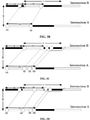
- the vehicles needing to wait at the downstream intersection to pass are the first n vehicles passing through the upstream intersection after the traffic light at the upstream intersection are steady green (for example, as shown in FIG.
- the duration of a red light of the traffic light at the downstream intersection relative to a red light of the traffic light at the upstream intersection is determined based on the phase difference between the traffic lights at the adjacent intersections, the distance between the adjacent intersections, and the green-wave coordination speed.
- the ratio of the duration of the red light to the first duration is used as the theoretical value of the intersection stop rate indicator.
- the speed of the vehicles running on the green-wave coordinated trunk is the green-wave coordination speed V.
- S denotes the distance between the adjacent intersections.
- M denotes the phase difference between the traffic lights at the adjacent intersections.
- G1 denotes the first duration.
- C denotes the period of the traffic light at the intersection B.
- the running duration S/V required for any vehicle running from the intersection A to the intersection B is acquired by dividing the distance S between the adjacent intersections to the green-wave coordination speed V. Since the vehicle Q1 needs to wait at the intersection B to pass, it indicates that the phase difference M between the traffic light at the intersection A and the traffic light at the intersection B is greater than the running duration S/V.
- the duration of the red light M - S/V of the traffic light at the downstream intersection relative to the traffic light at the upstream intersection is acquired by subtracting the running duration S/V from the phase difference M between the traffic light at the intersection A and the traffic light at the intersection B. Then the ratio (M - S/V)/G1 of the acquired duration of the red light to the first duration G1 is used as the theoretical value of the intersection stop rate indicator.
- the average duration in which the vehicles pass from the upstream intersection through the downstream intersection is determined based on the phase difference between the traffic lights at the adjacent intersections, the distance between the adjacent intersections, the green-wave coordination speed, the period of the traffic light at the downstream intersection, and the first duration.
- the theoretical value of the road section speed indicator is determined based on the distance between the adjacent intersections and the average duration.
- C denotes the period of the traffic light at the downstream intersection.
- the average duration L1 in which vehicles pass from the intersection A through the intersection B within the duration of the red light is acquired by multiplying ((M - S/V)/2 + S/V) by the theoretical value (M - S/V) of the intersection stop rate indicator. Further, based on the preceding description, it is known that the theoretical value of the intersection stop rate indicator is (M - S/V) and thus that the passing rate at the intersection is 1 - (M - S/V)/G1.
- the average duration L2 in which vehicles pass from the intersection A through the intersection B within the second duration G2 of the intersection B staying green is acquired by multiplying (1 - (M - S/V)/G1) by S/V
- the theoretical value of the road section speed indicator is acquired by dividing the distance S between the adjacent intersections by the sum of the average durations (L1 and L2).
- the vehicles needing to wait at the downstream intersection to pass are the last n vehicles passing through the upstream intersection after the traffic light at the upstream intersection is steady green (for example, as shown in FIG. 3C , for the two intersections A and B, the intersection A is the upstream intersection and the intersection B is the downstream intersection; the vehicle Q1 passing through the intersection A, the vehicle Q2 passing through the intersection A, and other vehicles (not shown in FIG. 3C ) between the vehicle Q1 and the vehicle Q2 may pass through the intersection B directly; and a vehicle Q3 passing through the intersection A, a vehicle Q4 passing through the intersection A, and other vehicles (not shown in FIG.
- the time the last vehicle passing through the upstream intersection spends reaching the downstream intersection is determined based on the first duration, the distance between the adjacent intersections, and the green-wave coordination speed.
- the duration of the red light of the traffic light at the downstream intersection relative to the red light of the traffic light at the upstream intersection is determined based on the determined time, the second duration, and the phase difference between the traffic lights at the adjacent intersections.
- the ratio of the duration of the red light to the first duration is used as the theoretical value of the intersection stop rate indicator.
- the running duration S/V required for any vehicle running from the intersection A to the intersection B is acquired by dividing the distance S between the adjacent intersections to the green-wave coordination speed V.
- the time the vehicle Q4 (the last vehicle passing through the upstream intersection) spends reaching the intersection B is the second duration G1 plus the running duration S/V.
- the duration of the red light (G1 + S/V) - G2 - M of the traffic light at the downstream intersection (that is, the traffic light at the intersection B) relative to the traffic light at the upstream intersection (that is, the traffic light at the intersection A) is acquired by subtracting the second duration G2 and the phase difference M between the traffic light at the intersection A and the traffic light at the intersection B from the determined time G1 + S/V.
- the ratio (G1 + S/V) - G2 - M)/G1 of the acquired duration of the red light to the first duration G1 is used as the theoretical value of the intersection stop rate indicator.
- the average duration in which the vehicles pass from the upstream intersection through the downstream intersection is determined based on the phase difference M between the traffic lights at the adjacent intersections, the distance S between the adjacent intersections, the green-wave coordination speed V, the period C of the traffic light at the downstream intersection, and the first duration G1.
- the theoretical value of the road section speed indicator is determined based on the distance S between the adjacent intersections and the average duration.
- the running duration S/V required for any vehicle running from the intersection A to the intersection B is acquired by dividing the distance S between the adjacent intersections to the green-wave coordination speed V. Since the vehicle Q1 does not need to wait at the intersection B to pass, it indicates that the phase difference M between the traffic light at the intersection A and the traffic light at the intersection B is smaller than the running duration S/V That is, the running duration required for the vehicle Q1 running from the intersection A to the intersection B is the time for the vehicle Q1 reaching the intersection B.
- the duration in which no vehicle may pass through after the intersection B is steady green is acquired by using the running duration S/V - M of the vehicle Q1.
- the duration C - (S/V - M) in which all the vehicles reaching the intersection B from the intersection A pass through the intersection B is acquired by subtracting the calculated duration S/V - M from the period C of the traffic light at the downstream intersection. Further, the average duration (C - (S/V - M) + G1)/2 in which the vehicles pass from the upstream intersection through the downstream intersection is acquired by averaging the sum of the first duration G1 and the duration C - (S/V - M) in which all the vehicles reaching the intersection B from the intersection A pass through the intersection B.
- the vehicles needing to wait at the downstream intersection to pass are the first n vehicles and last n vehicles passing through the upstream intersection after the traffic light at the upstream intersection is steady green (for example, as shown in FIG. 3D , for the two intersections A and B, the intersection A is the upstream intersection and the intersection B is the downstream intersection; the vehicle Q1 firstly passing through the intersection A needs to wait at the intersection B to pass; the vehicle Q3 passing through the intersection A, the vehicle Q4 passing through the intersection A, and other vehicles (not shown in FIG.
- the green light passing rate G2/G1 at the intersection is acquired by dividing the second duration G2 by the first duration G1. Then the theoretical value of the intersection stop rate indicator is acquired by subtracting G2/G1 from 1.
- the average duration in which the vehicles pass from the upstream intersection through the downstream intersection is determined based on the phase difference between the traffic lights at the adjacent intersections, the distance between the adjacent intersections, the green-wave coordination speed, the period of the traffic light at the downstream intersection, and the first duration.
- the theoretical value of the road section speed indicator is determined based on the distance between the adjacent intersections and the average duration.
- the running duration S/V required for any vehicle running from the intersection A to the intersection B is acquired by dividing the distance S between the adjacent intersections to the green-wave coordination speed V. Since the vehicle Q1 needs to wait at the intersection B to pass, it indicates that the phase difference M between the traffic light at the intersection A and the traffic light at the intersection B is greater than the running duration S/V. Accordingly, the duration of the red light M - S/V of the traffic light at the downstream intersection relative to the traffic light at the upstream intersection is acquired by subtracting the running duration S/V from the phase difference M between the traffic light at the intersection A and the traffic light at the intersection B.
- the duration C + (M - S/V) in which all the vehicles reaching the intersection B from the intersection A pass through the intersection B is acquired by adding the period C of the traffic light at the downstream intersection to the duration of the red light M - S/V. Further, the average duration (C + (M - S/V) + G1)/2 in which the vehicles running from the upstream intersection to the downstream intersection pass through the downstream intersection is acquired by averaging the sum of the first duration G1 and the duration C + (M - S/V) in which all the vehicles reaching the intersection B from the intersection A pass through the intersection B. Then the theoretical value S/((C + (M - S/V) + G1)/2) of the road section speed indicator is acquired by diving the distance S between the adjacent intersections by the average duration (C + (M - S/V) + G1)/2.
- the theoretical value of the intersection stop rate indicator can be determined by selecting a corresponding manner based on the vehicle passing condition at the intersection. Further, since the intersection stop rate is based on the passing condition for vehicles running from an upstream intersection to a downstream intersection, the intersection stop rate indicator on the green-wave coordinated trunk may be ignored in the case where the green-wave coordinated trunk is a one-way trunk. Moreover, the green-wave coordination speed is ideal. If the green-wave coordination speed is directed compared with the actual speed (that is, the actual value of the road section speed indicator), the accuracy of determining the reasonability of the timing coordination data is relatively low.
- the present disclosure combines a plurality of scenarios possibly existing in actual scenarios.
- the theoretical value of the road section speed indicator is determined based on multi-dimensional data including the data of green-wave coordination, the distance between the adjacent intersections, and the timing coordination data. Moreover, the determined theoretical value is compared with the acquired actual value. Accordingly, the reasonability of the timing coordination data can be determined truthfully and accurately from the perspective of speed. Additionally, through combining a plurality of scenarios possibly existing in actual scenarios, this embodiment provides a plurality of manners for calculating the theoretical value of the intersection stop rate indicator, greatly expanding the usage scenarios of the solutions and enabling the reasonability of the timing coordination data to be analyzed thoroughly from the perspective of intersections.
- the reasonability of the timing coordination data of the intersection traffic light on the green-wave coordinated trunk is verified based on the theoretical value of the intersection stop rate indicator and the actual value of the intersection stop rate indicator and/or the theoretical value of the road section speed indicator and the actual value of the road section speed indicator.
- the theoretical value of the intersection stop rate indicator and the theoretical value of road section speed indicator are determined based on multi-dimensional data including the data of green-wave coordination, the distance between the adjacent intersections, and the timing coordination data. Accordingly, an optional manner for the theoretical value of the intersection stop rate indicator and the theoretical value of the road section speed indicator is provided, thus providing data support for subsequently verifying the reasonability of the timing coordination data. Moreover, the timing coordination data is analyzed from the perspective of intersections so that an unreasonable phenomenon of a specific intersection can be positioned directly, facilitating targeted adjustment and enhancing adjustment efficiency.
- FIG. 4A is a flowchart of another data verification method according to embodiments of the present disclosure. Based on the preceding embodiments, embodiments of the present disclosure make further descriptions on how to determine the theoretical value of the evaluation indicator. As shown in FIG. 4A , the data verification method provided in this embodiment may include the steps below.
- the actual value of the evaluation indicator of the timing coordination data of the intersection traffic lights on the green-wave coordinated trunk is determined.
- the evaluation indicator includes at least one of the intersection stop rate indicator, the road section speed indicator, the trunk speed indicator, or the trunk stop count indicator.
- the vehicle passing condition on the green-wave coordinated trunk is determined based on the timing coordination data of the intersection traffic lights on the green-wave coordinated trunk, the location data of the intersections on the green-wave coordinated trunk, and the trajectory data of the vehicle running on the green-wave coordinated trunk.
- a running duration in which the vehicles run from the starting intersection on the green-wave coordinated trunk and passes through an ending intersection on the green-wave coordinated trunk and/or the theoretical value of the trunk stop count indicator are determined based on the phase difference between the traffic lights at the adjacent intersections, the period of the traffic light at an intersection, the duration in which the traffic light at the intersection is steady green, the distance between the adjacent intersections, and the green-wave coordination speed.
- the running duration in which the vehicle runs from the starting intersection on the green-wave coordinated trunk and passes through the ending intersection on the green-wave coordinated trunk is determined based on the phase difference M between the traffic lights at the adjacent intersections, the period C of the traffic light at an intersection, the duration L in which the traffic light at the intersection is steady green, the distance S between the adjacent intersections, and the green-wave coordination speed V.
- a total of four intersections (that is, an intersection A, an intersection B, an intersection E, and an intersection D) are on the green-wave coordinated trunk.
- the starting intersection is the intersection A
- the ending intersection is the intersection D.
- M1 denotes the phase difference between the traffic light at the intersection A and the traffic light at the intersection B.
- M2 denotes the phase difference between the traffic light at the intersection B and the traffic light at the intersection E.
- M3 denotes the phase difference between the traffic light at the intersection E and the traffic light at the intersection D.
- G1 denotes the duration in which the traffic light at the intersection A is steady green.
- G2 denotes the duration in which the traffic light at the intersection B is steady green.
- G3 denotes the duration in which the traffic light at the intersection E is steady green.
- G4 denotes the duration in which the traffic light at the intersection D is steady green.
- C1 denotes the period of the traffic light at the intersection A.
- C2 denotes the period of the traffic light at the intersection B.
- C3 denotes the period of the traffic light at the intersection E.
- C4 denotes the period of the traffic light at the intersection D.
- S1 denotes the distance between the intersection A and the intersection B.
- S2 denotes the distance between the intersection B and the intersection E.
- S3 denotes the distance between the intersection E and the intersection D.
- the duration L1 in which the vehicle Q1 passes from the intersection A through the intersection B is acquired by dividing S1 by the green-wave coordination speed V; the duration L2 in which the vehicle Q1 passes from the intersection B through the intersection E is acquired by dividing S2 by the green-wave coordination speed V; the duration L3 in which the vehicle Q1 reaches the intersection D from the intersection E is acquired by dividing S3 by the green-wave coordination speed V; and the duration L4 in which the vehicle Q1 passes from the intersection E through the intersection D is determined in combination with, for example, the period C4 of the traffic light at the intersection D, the duration G4 in which the traffic light at the intersection D is steady green, and the duration L3 in which the vehicle Q1 reaches the intersection D from the intersection E.
- the running duration in which the vehicle Q1 passes from the intersection A through the intersection D is acquired by adding L1, L2, and L4.
- the duration L5 in which the vehicle Q2 passes from the intersection A through the intersection B is acquired by dividing S1 by the green-wave coordination speed V; the duration L6 in which the vehicle Q2 passes from the intersection B through the intersection E is acquired by dividing S2 by the green-wave coordination speed V; and the duration L7 in which the vehicle Q1 passes from the intersection E through the intersection D is acquired by dividing S3 by the green-wave coordination speed V.
- the running duration in which the vehicle Q2 passes from the intersection A through the intersection D is acquired by adding L5, L6, and L7.
- the running duration in which the vehicle Q3 runs from the intersection A and passes through the intersection D is determined in combination of the green-wave coordination speed V, the phase difference M1 between the traffic light at the intersection A and the traffic light at the intersection B, the phase difference M2 between the traffic light at the intersection B and the traffic light at the intersection E, the phase difference M3 between the traffic light at the intersection E and the traffic light at the intersection D, the duration G2 in which the traffic light at the intersection B is steady green, the duration G3 in which the traffic light at the intersection E is steady green, the duration G4 in which the traffic light at the intersection D is steady green, the period C2 of the traffic light at the intersection B, the period C3 of the traffic light at the intersection E, the period C4 of the traffic light at the intersection D, the distance S1 between the intersection A and the intersection B, the distance S2 between the intersection B and the intersection E, and the distance S3 between the intersection E and the intersection D.
- the stops for a vehicle running from the starting intersection on the green-wave coordinated trunk and passing through the ending intersection on the green-wave coordinated trunk may be determined based on the phase difference M between the traffic lights at the adjacent intersections, the period C of the traffic light at an intersection, the duration L in which the traffic light at the intersection is steady green, the distance S between the adjacent intersections, and the green-wave coordination speed V.
- the running duration in which the vehicle runs from the upstream intersection of two adjacent intersections to the downstream intersection of two adjacent intersections is determined based on the green-wave coordination speed and the distance between the adjacent intersections.
- the duration in which the traffic light at the upstream intersection is steady green is steady green
- the duration in which the traffic light at the downstream intersection is steady green is steady green
- the phase difference between the traffic lights at the adjacent intersections it is judged whether the traffic light at the downstream intersection is steady green when the vehicle reaches the downstream intersection. If the traffic light does not stay green, it is determined that the vehicle needs to stop and wait at the downstream intersection. In this case, the number of stops for the vehicle is plus 1. The preceding process is repeated before the number of stops for the vehicle passing from the starting intersection on the green-wave coordinated trunk through the ending intersection on the green-wave coordinated trunk is counted.
- the numbers of stops for all the vehicles are averaged. The average value is taken as the theoretical value of the trunk stop count indicator.
- the theoretical value of the trunk stop count indicator is determined based on the running duration and the distance between the starting intersection on the green-wave coordinated trunk and the ending intersection on the green-wave coordinated trunk.
- the speed at which the vehicle runs on the green-wave coordinated trunk is acquired by dividing the distance between the starting intersection on the green-wave coordinated trunk and the ending intersection on the green-wave coordinated trunk by the running duration of the vehicle.
- the speeds of all the vehicles are averaged.
- the average value is taken as the theoretical value of the trunk speed indicator.
- the theoretical value of the trunk stop count indicator and the theoretical value of the trunk speed indicator are determined based on various types of data including the data of green-wave coordination, the distance between the adjacent intersections, and the timing coordination data. Accordingly, an optional manner for the theoretical value of the trunk stop count indicator and the theoretical value of the trunk speed indicator is provided, thus providing data support for subsequently verifying the reasonability of the timing coordination data.
- FIG. 5 is a diagram illustrating the structure of a data verification apparatus according to embodiments of the present disclosure.
- the apparatus can implement the data verification method of embodiments of the present disclosure.
- the apparatus can be integrated into a computing device carrying the function of data verification.
- the data verification apparatus 500 specifically includes an actual value determination module 501, a theoretical value determination module 502, and a verification module 503.
- the actual value determination module 501 is configured to determine the actual value of an evaluation indicator of the timing coordination data of intersection traffic lights on a green-wave coordinated trunk.
- the evaluation indicator includes at least one of an intersection stop rate indicator, a road section speed indicator, a trunk speed indicator, or a trunk stop count indicator.
- the theoretical value determination module 502 is configured to determine the theoretical value of the evaluation indicator based on the timing coordination data of the intersection traffic lights on the green-wave coordinated trunk, location data of intersections on the green-wave coordinated trunk, and the trajectory data of vehicle running on the green-wave coordinated trunk.
- the verification module 503 is configured to verify the reasonability of the timing coordination data of the intersection traffic lights on the green-wave coordinated trunk based on the theoretical value of the evaluation indicator and the actual value of the evaluation indicator.
- the theoretical value of the evaluation indicator is determined based on the timing coordination data of the intersection traffic lights on the green-wave coordinated trunk, the location data of the intersections on the green-wave coordinated trunk, and the trajectory data of the vehicle running on the green-wave coordinated trunk. Moreover, the reasonability of the timing coordination data of the intersection traffic lights on the green-wave coordinated trunk is verified based on the theoretical value of the evaluation indicator and the acquired actual value of the evaluation indicator. In the preceding solution, the timing coordination data is evaluated thoroughly from three perspectives, intersections, road sections, and the trunk so as to determine the reasonability of the timing coordination data of the intersection traffic lights intuitively, truthfully, and accurately.
- this solution is based on the trajectory data of all the vehicles running on the green-wave coordinated trunk, that is, based on an abundant amount of data, which greatly improves the accuracy of determining the reasonability of the timing coordination data of the intersection traffic lights and provides an optimized new idea of verifying the reasonability of the timing coordination data
- the theoretical value determination module 502 includes a passing condition determination unit and a theoretical value determination unit.
- the passing condition determination unit is configured to determine the vehicle passing condition at a downstream intersection of adjacent intersections on the green-wave coordinated trunk and/or the vehicle passing condition on the green-wave coordinated trunk based on the timing coordination data of the intersection traffic lights on the green-wave coordinated trunk, location data of intersections on the green-wave coordinated trunk, and the trajectory data of the vehicle running on the green-wave coordinated trunk.
- the theoretical value determination unit is configured to determine the theoretical value of the evaluation indicator based on the vehicle passing condition at the downstream intersection and/or the vehicle passing condition on the trunk, the green-wave coordination speed, the timing coordination data, and the distance between the adjacent intersections.
- the theoretical value determination unit is specifically configured to, in response to the vehicle passing condition at the downstream intersection being that vehicles needing to wait, at the downstream intersection, to pass exists among vehicles running from the upstream intersection to the downstream intersection, determine the theoretical value of the intersection stop rate indicator and/or the theoretical value of the road section speed indicator based on the distance between the adjacent intersections, the green-wave coordination speed, and the adjacent-intersection traffic light data in the timing coordination data.
- the adjacent-intersection traffic light data includes a first duration in which the traffic light at the upstream intersection of the adjacent intersections is steady green, a second duration in which the traffic light at the downstream intersection of the adjacent intersections is steady green, the phase difference between the traffic lights at the adjacent intersections, and the period of the traffic light at the downstream intersection.
- the theoretical value determination unit is specifically configured to determine, based on the first duration, the distance between the adjacent intersections, and the green-wave coordination speed, the time the last vehicle passing through the upstream intersection spends reaching the downstream intersection; determine a duration of the red light of the traffic light at the downstream intersection relative to the traffic light at the upstream intersection based on the determined time, the second duration, and the phase difference between the traffic lights at the adjacent intersections; and use a ratio of the duration of the red light to the first duration as the theoretical value of the intersection stop rate indicator.
- the theoretical value determination unit is specifically configured to determine a duration of a red light of the traffic light at the downstream intersection relative to a red light of the traffic light at the upstream intersection based on the phase difference between the traffic lights at the adjacent intersections, the distance between the adjacent intersections, and the green-wave coordination speed and use a ratio of the duration of the red light to the first duration as the theoretical value of the intersection stop rate indicator.
- the theoretical value determination unit is specifically configured to determine an average duration in which the vehicles pass from the upstream intersection through the downstream intersection based on the phase difference between the traffic lights at the adjacent intersections, the distance between the adjacent intersections, the green-wave coordination speed, the period of the traffic light at the downstream intersection, and the first duration and determine the theoretical value of the road section speed indicator based on the distance between the adjacent intersections and the average duration.
- the theoretical value determination unit is specifically configured to, in response to the vehicle passing condition on the trunk being that vehicles waiting to pass exists among the vehicles running on the green-wave coordinated trunk, determine a running duration in which the vehicles run from the starting intersection on the green-wave coordinated trunk and passes through an ending intersection on the green-wave coordinated trunk and/or the theoretical value of the trunk stop count indicator based on the phase difference between the traffic lights at the adjacent intersections, the period of the traffic light at an intersection, the duration in which the traffic light at the intersection is steady green, the distance between the adjacent intersections, and the green-wave coordination speed; and determine the theoretical value of the trunk stop count indicator based on the running duration and the distance between the starting intersection on the green-wave coordinated trunk and the ending intersection on the green-wave coordinated trunk.
- an execution subject of the data verification method can obtain the data (for example, the trajectory data of the vehicles) used for data verification in embodiments of the present disclosure in various public, legal and compliant manners.
- the data may be obtained from a public data set or obtained from a user through the user's authorization.
- the present disclosure further provides an electronic device, a readable storage medium, and a computer program product.
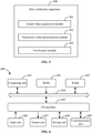
- FIG. 6 is a block diagram of an exemplary electronic device 600 that may be configured to implement the embodiments of the present disclosure.
- Electronic devices are intended to represent various forms of digital computers, for example, laptop computers, desktop computers, worktables, personal digital assistants, servers, blade servers, mainframe computers, and other applicable computers.
- Electronic devices may further represent various forms of mobile apparatuses, for example, personal digital assistants, cellphones, smartphones, wearable devices, and other similar computing apparatuses.
- the shown components, the connections and relationships between these components, and the functions of these components are illustrative only and are not intended to limit the implementation of the present disclosure as described and/or claimed herein.
- the device 600 includes a computing unit 601.
- the computing unit 602 may perform various appropriate actions and processing according to a computer program stored in a read-only memory (ROM) 602 or a computer program loaded into a random-access memory (RAM) 603 from a storage unit 608.
- Various programs and data required for the operation of the electronic device 600 are also stored in the RAM 603.
- the computing unit 601, the ROM 602, and the RAM 603 are connected to each other through a bus 604.
- An input/output (I/O) interface 605 is also connected to the bus 604.
- the multiple components include an input unit 606 such as a keyboard and a mouse, an output unit 607 such as various types of displays and speakers, the storage unit 608 such as a magnetic disk and an optical disk, and a communication unit 609 such as a network card, a modem, and a wireless communication transceiver.
- the communication unit 609 allows the device 600 to exchange information/data with other devices over a computer network such as the Internet and/or various telecommunications networks.
- the computing unit 601 may be various general-purpose and/or special-purpose processing components having processing and computing capabilities. Examples of the computing unit 601 include, but are not limited to, a central processing unit (CPU), a graphics processing unit (GPU), a special-purpose artificial intelligence (AI) computing chip, a computing unit executing machine learning models and algorithms, a digital signal processor (DSP) and any appropriate processor, controller, and microcontroller.
- the computing unit 601 performs the preceding methods and processing, such as a data verification method.
- the data verification method may be implemented as a computer software program tangibly contained in a machine-readable medium such as the storage unit 608.
- part or all of computer programs may be loaded and/or installed on the electronic device 600 via the ROM 602 and/or the communication unit 609.
- the computer program When the computer program is loaded to the RAM 603 and executed by the computing unit 601, one or more steps of the preceding data verification method may be executed.
- the computing unit 601 may be configured, in any other suitable manner (for example, by means of firmware), to perform the data verification method.
- various embodiments of the systems and techniques described above may be implemented in digital electronic circuitry, integrated circuitry, field-programmable gate arrays (FPGAs), application-specific integrated circuits (ASICs), application-specific standard products (ASSPs), systems on chips (SOCs), complex programmable logic devices (CPLDs), computer hardware, firmware, software, and/or combinations thereof.
- the various embodiments may include implementations in one or more computer programs.
- the one or more computer programs are executable and/or interpretable on a programmable system including at least one programmable processor.
- the programmable processor may be a special-purpose or general-purpose programmable processor for receiving data and instructions from a memory system, at least one input apparatus, and at least one output apparatus and transmitting the data and instructions to the memory system, the at least one input apparatus, and the at least one output apparatus.
- Program codes for implementing the methods of the present disclosure may be compiled in any combination of one or more programming languages.
- the program codes may be provided for the processor or controller of a general-purpose computer, a special-purpose computer, or another programmable data processing apparatus to enable functions/operations specified in flowcharts and/or block diagrams to be implemented when the program codes are executed by the processor or controller.
- the program codes may be executed in whole on a machine, executed in part on a machine, executed, as a stand-alone software package, in part on a machine, and in part on a remote machine, or executed in whole on a remote machine or a server.
- a machine-readable medium may be a tangible medium that may include or store a program that is used by or in conjunction with a system, apparatus or device that executes instructions.
- the machine-readable medium may be a machine-readable signal medium or a machine-readable storage medium.
- the machine-readable medium may include, but is not limited to, an electronic, magnetic, optical, electromagnetic, infrared or semiconductor system, apparatus or device, or any suitable combination thereof.
- machine-readable storage medium may include an electrical connection based on one or more wires, a portable computer disk, a hard disk, a random-access memory (RAM), a read-only memory (ROM), an erasable programmable read-only memory (EPROM) or a flash memory, an optical fiber, a portable compact disk read-only memory (CD-ROM), an optical memory device, a magnetic memory device, or any suitable combination thereof.
- RAM random-access memory
- ROM read-only memory
- EPROM erasable programmable read-only memory
- flash memory an optical fiber
- CD-ROM portable compact disk read-only memory
- CD-ROM compact disk read-only memory
- magnetic memory device or any suitable combination thereof.
- the systems and techniques described herein may be implemented on a computer.
- the computer has a display apparatus (for example, a cathode-ray tube (CRT) or a liquid-crystal display (LCD) monitor) for displaying information to the user and a keyboard and a pointing apparatus (for example, a mouse or a trackball) through which the user can provide input to the computer.
- a display apparatus for example, a cathode-ray tube (CRT) or a liquid-crystal display (LCD) monitor
- keyboard and a pointing apparatus for example, a mouse or a trackball
- Other types of apparatuses may also be used for providing interaction with a user.
- feedback provided for the user may be sensory feedback in any form (for example, visual feedback, auditory feedback, or haptic feedback).
- input from the user may be received in any form (including acoustic input, voice input, or haptic input).
- the systems and techniques described herein may be implemented in a computing system including a back-end component (for example, a data server), a computing system including a middleware component (for example, an application server), a computing system including a front-end component (for example, a client computer having a graphical user interface or a web browser through which a user can interact with implementations of the systems and techniques described herein), or a computing system including any combination of such back-end, middleware or front-end components.
- Components of a system may be interconnected by any form or medium of digital data communication (for example, a communication network). Examples of the communication network include a local area network (LAN), a wide area network (WAN), a blockchain network, and the Internet.
- the computing system may include clients and servers.
- the clients and servers are usually far away from each other and generally interact through the communication network.
- the relationship between the clients and the servers arises by virtue of computer programs running on respective computers and having a client-server relationship to each other.
- the server may be a cloud server, also referred to as a cloud computing server or a cloud host.
- the server solves the defects of difficult management and weak business scalability in conventional physical hosts and VPS services.
Landscapes
- Physics & Mathematics (AREA)
- General Physics & Mathematics (AREA)
- Engineering & Computer Science (AREA)
- Chemical & Material Sciences (AREA)
- Analytical Chemistry (AREA)
- Mathematical Physics (AREA)
- Theoretical Computer Science (AREA)
- Data Mining & Analysis (AREA)
- Mathematical Analysis (AREA)
- Mathematical Optimization (AREA)
- Computational Mathematics (AREA)
- Pure & Applied Mathematics (AREA)
- Databases & Information Systems (AREA)
- Software Systems (AREA)
- General Engineering & Computer Science (AREA)
- Algebra (AREA)
- Operations Research (AREA)
- Traffic Control Systems (AREA)
Applications Claiming Priority (1)
| Application Number | Priority Date | Filing Date | Title |
|---|---|---|---|
| CN202110620461.9A CN113380029B (zh) | 2021-06-03 | 2021-06-03 | 数据验证方法、装置、设备及存储介质 |
Publications (2)
| Publication Number | Publication Date |
|---|---|
| EP3961597A2 true EP3961597A2 (de) | 2022-03-02 |
| EP3961597A3 EP3961597A3 (de) | 2022-08-10 |
Family
ID=77575676
Family Applications (1)
| Application Number | Title | Priority Date | Filing Date |
|---|---|---|---|
| EP22151595.0A Withdrawn EP3961597A3 (de) | 2021-06-03 | 2022-01-14 | Datenverifizierungsverfahren und -gerät, vorrichtung und speichermedium |
Country Status (5)
| Country | Link |
|---|---|
| US (1) | US20220139218A1 (de) |
| EP (1) | EP3961597A3 (de) |
| JP (1) | JP2022186596A (de) |
| KR (1) | KR20220024314A (de) |
| CN (1) | CN113380029B (de) |
Families Citing this family (4)
| Publication number | Priority date | Publication date | Assignee | Title |
|---|---|---|---|---|
| CN114038079B (zh) * | 2021-10-19 | 2024-05-24 | 青岛海信网络科技股份有限公司 | 道路巡检方法及电子设备 |
| CN114818326B (zh) * | 2022-04-26 | 2024-12-13 | 山东交控科技有限公司 | 城市轨道交通电子地图的验证方法及装置 |
| CN115168523A (zh) * | 2022-07-21 | 2022-10-11 | 中寰卫星导航通信有限公司 | 数据验证方法、装置及存储介质 |
| US12515668B2 (en) * | 2023-02-20 | 2026-01-06 | Honda Motor Co., Ltd. | Systems and methods for vehicular navigation at traffic signals |
Citations (1)
| Publication number | Priority date | Publication date | Assignee | Title |
|---|---|---|---|---|
| CN106023591B (zh) * | 2016-06-20 | 2018-05-29 | 北方工业大学 | 一种城市干线绿波控制评估方法及装置 |
Family Cites Families (7)
| Publication number | Priority date | Publication date | Assignee | Title |
|---|---|---|---|---|
| JP3509906B2 (ja) * | 1993-10-29 | 2004-03-22 | 三菱電機株式会社 | 道路交通信号制御適正化装置、およびそれを用いた道路交通流管制システム |
| CN103632555B (zh) * | 2013-11-28 | 2015-12-02 | 东南大学 | 一种基于绿波带宽度最大化的干道绿波协调控制配时方法 |
| CN104699956B (zh) * | 2015-02-02 | 2017-09-22 | 北京工业大学 | 一种基于移动终端的干线绿波协调效果评估方法 |
| CN109816977B (zh) * | 2019-01-25 | 2021-06-04 | 同济大学 | 一种数据驱动的交叉口信号控制评价系统 |
| CN111899536B (zh) * | 2019-05-06 | 2022-08-02 | 阿里巴巴集团控股有限公司 | 数据的处理方法、装置、设备及计算机存储介质 |
| CN111951567B (zh) * | 2019-05-14 | 2023-05-26 | 阿里巴巴集团控股有限公司 | 数据的处理方法、装置、设备及计算机存储介质 |
| CN111833620B (zh) * | 2020-06-17 | 2021-06-25 | 东南大学 | 一种过饱和交通状态干线单向信号协调设计方法与装置 |
-
2021
- 2021-06-03 CN CN202110620461.9A patent/CN113380029B/zh active Active
-
2022
- 2022-01-14 EP EP22151595.0A patent/EP3961597A3/de not_active Withdrawn
- 2022-01-18 US US17/577,803 patent/US20220139218A1/en not_active Abandoned
- 2022-02-08 KR KR1020220016534A patent/KR20220024314A/ko not_active Ceased
- 2022-03-31 JP JP2022059933A patent/JP2022186596A/ja active Pending
Patent Citations (1)
| Publication number | Priority date | Publication date | Assignee | Title |
|---|---|---|---|---|
| CN106023591B (zh) * | 2016-06-20 | 2018-05-29 | 北方工业大学 | 一种城市干线绿波控制评估方法及装置 |
Also Published As
| Publication number | Publication date |
|---|---|
| KR20220024314A (ko) | 2022-03-03 |
| CN113380029B (zh) | 2023-02-03 |
| CN113380029A (zh) | 2021-09-10 |
| EP3961597A3 (de) | 2022-08-10 |
| JP2022186596A (ja) | 2022-12-15 |
| US20220139218A1 (en) | 2022-05-05 |
Similar Documents
| Publication | Publication Date | Title |
|---|---|---|
| EP3961597A2 (de) | Verfahren und gerät zur datenverifizierung, vorrichtung und speichermedium | |
| US20230334986A1 (en) | Method of performing green wave coordination control, electronic device and storage medium | |
| US12422262B2 (en) | Navigation path planning method and apparatus, device, and storage medium | |
| US20230316902A1 (en) | Traffic flow migration situation display method and apparatus, device, medium and product | |
| EP4047582A2 (de) | Verfahren und vorrichtung zum erzeugen eines steuersignals für eine verkehrsampel, elektronische vorrichtung und medium | |
| EP4109431A1 (de) | Verfahren, vorrichtung und speichermedium zum bestimmen des kreuzungszustandes | |
| US20220044553A1 (en) | Method and apparatus for monitoring vehicle, and cloud control platform | |
| CN113129596B (zh) | 行驶数据处理方法、装置、设备、存储介质及程序产品 | |
| US11743154B2 (en) | Method and apparatus for processing network usage of a cloud product, device, storage medium and product | |
| US20230097364A1 (en) | Determination of driving direction | |
| US20220327921A1 (en) | Method of determining state of intersection, electronic device, and storage medium | |
| EP4231155B1 (de) | Leistungstestverfahren und -vorrichtung, elektronische vorrichtung und speichermedium | |
| CN113538915B (zh) | 交通拥堵事件的处理方法、设备、存储介质及程序产品 | |
| US20220381574A1 (en) | Multipath generation method, apparatus, device and storage medium | |
| US20230147521A1 (en) | High-precision-map data collection methods, device and storage medium | |
| CN113990068B (zh) | 交通数据的处理方法、装置、设备以及存储介质 | |
| CN114596707B (zh) | 交通控制方法及装置、设备、系统、介质 | |
| US20240273113A1 (en) | Method of importing data to database, electronic device, and storage medium | |
| CN112714037A (zh) | 一种线上服务质量的保障性能评估方法、装置及设备 | |
| CN116229714B (zh) | 一种交通特征获得方法、装置、设备及存储介质 | |
| CN114944078B (zh) | 信息处理方法、装置、设备、存储介质及计算机程序产品 | |
| CN112861024B (zh) | 确定路网矩阵的方法、装置、电子设备及存储介质 | |
| US12270672B2 (en) | Method for generating navigation information, apparatus for generating navigation information, device, medium, and product | |
| CN115861143B (zh) | 图像融合方法、装置、智能芯片和存储介质 | |
| CN115981773A (zh) | 页面数据的显示方法、装置、电子设备及存储介质 |
Legal Events
| Date | Code | Title | Description |
|---|---|---|---|
| PUAI | Public reference made under article 153(3) epc to a published international application that has entered the european phase |
Free format text: ORIGINAL CODE: 0009012 |
|
| STAA | Information on the status of an ep patent application or granted ep patent |
Free format text: STATUS: REQUEST FOR EXAMINATION WAS MADE |
|
| 17P | Request for examination filed |
Effective date: 20220114 |
|
| AK | Designated contracting states |
Kind code of ref document: A2 Designated state(s): AL AT BE BG CH CY CZ DE DK EE ES FI FR GB GR HR HU IE IS IT LI LT LU LV MC MK MT NL NO PL PT RO RS SE SI SK SM TR |
|
| PUAL | Search report despatched |
Free format text: ORIGINAL CODE: 0009013 |
|
| AK | Designated contracting states |
Kind code of ref document: A3 Designated state(s): AL AT BE BG CH CY CZ DE DK EE ES FI FR GB GR HR HU IE IS IT LI LT LU LV MC MK MT NL NO PL PT RO RS SE SI SK SM TR |
|
| RIC1 | Information provided on ipc code assigned before grant |
Ipc: G08G 1/082 20060101ALI20220701BHEP Ipc: G08G 1/01 20060101AFI20220701BHEP |
|
| STAA | Information on the status of an ep patent application or granted ep patent |
Free format text: STATUS: EXAMINATION IS IN PROGRESS |
|
| 17Q | First examination report despatched |
Effective date: 20230426 |
|
| STAA | Information on the status of an ep patent application or granted ep patent |
Free format text: STATUS: THE APPLICATION HAS BEEN WITHDRAWN |
|
| 18W | Application withdrawn |
Effective date: 20230811 |