EP3961332B1 - Method and device for adjusting quality determination conditions for test body - Google Patents
Method and device for adjusting quality determination conditions for test body Download PDFInfo
- Publication number
- EP3961332B1 EP3961332B1 EP21196822.7A EP21196822A EP3961332B1 EP 3961332 B1 EP3961332 B1 EP 3961332B1 EP 21196822 A EP21196822 A EP 21196822A EP 3961332 B1 EP3961332 B1 EP 3961332B1
- Authority
- EP
- European Patent Office
- Prior art keywords
- error
- determination
- inspection
- reference value
- good
- Prior art date
- Legal status (The legal status is an assumption and is not a legal conclusion. Google has not performed a legal analysis and makes no representation as to the accuracy of the status listed.)
- Active
Links
- 238000000034 method Methods 0.000 title claims description 36
- 238000007689 inspection Methods 0.000 claims description 464
- 230000002950 deficient Effects 0.000 claims description 137
- 238000012552 review Methods 0.000 claims description 97
- 238000005259 measurement Methods 0.000 claims description 66
- 238000009826 distribution Methods 0.000 claims description 64
- 238000012545 processing Methods 0.000 claims description 30
- 238000013461 design Methods 0.000 claims description 19
- 238000004891 communication Methods 0.000 claims description 15
- 230000008569 process Effects 0.000 description 19
- 238000003860 storage Methods 0.000 description 12
- 230000004044 response Effects 0.000 description 11
- 238000005286 illumination Methods 0.000 description 9
- 238000004519 manufacturing process Methods 0.000 description 9
- 230000014509 gene expression Effects 0.000 description 7
- 238000003384 imaging method Methods 0.000 description 5
- 229910000679 solder Inorganic materials 0.000 description 3
- 238000012546 transfer Methods 0.000 description 3
- 230000002159 abnormal effect Effects 0.000 description 2
- 230000009471 action Effects 0.000 description 2
- 230000008859 change Effects 0.000 description 2
- 238000013500 data storage Methods 0.000 description 2
- 238000010586 diagram Methods 0.000 description 2
- 230000007246 mechanism Effects 0.000 description 2
- 238000003491 array Methods 0.000 description 1
- 230000000295 complement effect Effects 0.000 description 1
- 230000007547 defect Effects 0.000 description 1
- 230000001419 dependent effect Effects 0.000 description 1
- 238000005315 distribution function Methods 0.000 description 1
- 239000004973 liquid crystal related substance Substances 0.000 description 1
- 229910044991 metal oxide Inorganic materials 0.000 description 1
- 150000004706 metal oxides Chemical class 0.000 description 1
- 238000012986 modification Methods 0.000 description 1
- 230000004048 modification Effects 0.000 description 1
- 230000003287 optical effect Effects 0.000 description 1
- 230000010363 phase shift Effects 0.000 description 1
- 230000000704 physical effect Effects 0.000 description 1
- 239000004065 semiconductor Substances 0.000 description 1
Images


Classifications
-
- G—PHYSICS
- G01—MEASURING; TESTING
- G01N—INVESTIGATING OR ANALYSING MATERIALS BY DETERMINING THEIR CHEMICAL OR PHYSICAL PROPERTIES
- G01N21/00—Investigating or analysing materials by the use of optical means, i.e. using sub-millimetre waves, infrared, visible or ultraviolet light
- G01N21/84—Systems specially adapted for particular applications
- G01N21/88—Investigating the presence of flaws or contamination
- G01N21/8851—Scan or image signal processing specially adapted therefor, e.g. for scan signal adjustment, for detecting different kinds of defects, for compensating for structures, markings, edges
-
- G—PHYSICS
- G05—CONTROLLING; REGULATING
- G05B—CONTROL OR REGULATING SYSTEMS IN GENERAL; FUNCTIONAL ELEMENTS OF SUCH SYSTEMS; MONITORING OR TESTING ARRANGEMENTS FOR SUCH SYSTEMS OR ELEMENTS
- G05B19/00—Programme-control systems
- G05B19/02—Programme-control systems electric
- G05B19/418—Total factory control, i.e. centrally controlling a plurality of machines, e.g. direct or distributed numerical control [DNC], flexible manufacturing systems [FMS], integrated manufacturing systems [IMS] or computer integrated manufacturing [CIM]
- G05B19/41875—Total factory control, i.e. centrally controlling a plurality of machines, e.g. direct or distributed numerical control [DNC], flexible manufacturing systems [FMS], integrated manufacturing systems [IMS] or computer integrated manufacturing [CIM] characterised by quality surveillance of production
-
- G—PHYSICS
- G01—MEASURING; TESTING
- G01N—INVESTIGATING OR ANALYSING MATERIALS BY DETERMINING THEIR CHEMICAL OR PHYSICAL PROPERTIES
- G01N21/00—Investigating or analysing materials by the use of optical means, i.e. using sub-millimetre waves, infrared, visible or ultraviolet light
- G01N21/84—Systems specially adapted for particular applications
- G01N21/88—Investigating the presence of flaws or contamination
-
- G—PHYSICS
- G01—MEASURING; TESTING
- G01N—INVESTIGATING OR ANALYSING MATERIALS BY DETERMINING THEIR CHEMICAL OR PHYSICAL PROPERTIES
- G01N21/00—Investigating or analysing materials by the use of optical means, i.e. using sub-millimetre waves, infrared, visible or ultraviolet light
- G01N21/17—Systems in which incident light is modified in accordance with the properties of the material investigated
- G01N21/1717—Systems in which incident light is modified in accordance with the properties of the material investigated with a modulation of one or more physical properties of the sample during the optical investigation, e.g. electro-reflectance
-
- G—PHYSICS
- G01—MEASURING; TESTING
- G01N—INVESTIGATING OR ANALYSING MATERIALS BY DETERMINING THEIR CHEMICAL OR PHYSICAL PROPERTIES
- G01N21/00—Investigating or analysing materials by the use of optical means, i.e. using sub-millimetre waves, infrared, visible or ultraviolet light
- G01N21/17—Systems in which incident light is modified in accordance with the properties of the material investigated
- G01N2021/1765—Method using an image detector and processing of image signal
- G01N2021/177—Detector of the video camera type
-
- G—PHYSICS
- G01—MEASURING; TESTING
- G01N—INVESTIGATING OR ANALYSING MATERIALS BY DETERMINING THEIR CHEMICAL OR PHYSICAL PROPERTIES
- G01N21/00—Investigating or analysing materials by the use of optical means, i.e. using sub-millimetre waves, infrared, visible or ultraviolet light
- G01N21/84—Systems specially adapted for particular applications
- G01N21/88—Investigating the presence of flaws or contamination
- G01N21/8851—Scan or image signal processing specially adapted therefor, e.g. for scan signal adjustment, for detecting different kinds of defects, for compensating for structures, markings, edges
- G01N2021/8854—Grading and classifying of flaws
- G01N2021/8858—Flaw counting
-
- G—PHYSICS
- G01—MEASURING; TESTING
- G01N—INVESTIGATING OR ANALYSING MATERIALS BY DETERMINING THEIR CHEMICAL OR PHYSICAL PROPERTIES
- G01N21/00—Investigating or analysing materials by the use of optical means, i.e. using sub-millimetre waves, infrared, visible or ultraviolet light
- G01N21/84—Systems specially adapted for particular applications
- G01N21/88—Investigating the presence of flaws or contamination
- G01N21/8851—Scan or image signal processing specially adapted therefor, e.g. for scan signal adjustment, for detecting different kinds of defects, for compensating for structures, markings, edges
- G01N2021/8887—Scan or image signal processing specially adapted therefor, e.g. for scan signal adjustment, for detecting different kinds of defects, for compensating for structures, markings, edges based on image processing techniques
-
- G—PHYSICS
- G01—MEASURING; TESTING
- G01N—INVESTIGATING OR ANALYSING MATERIALS BY DETERMINING THEIR CHEMICAL OR PHYSICAL PROPERTIES
- G01N35/00—Automatic analysis not limited to methods or materials provided for in any single one of groups G01N1/00 - G01N33/00; Handling materials therefor
- G01N35/00584—Control arrangements for automatic analysers
- G01N35/00722—Communications; Identification
- G01N2035/00891—Displaying information to the operator
- G01N2035/0091—GUI [graphical user interfaces]
Definitions
- the present disclosure relates to a method and a device for adjusting a condition for determining a quality of an inspection object.
- manufacturers are making efforts to remove defective products during the production, assembly, intermediate process, and final assembly process. In such processes, manufacturers determine a quality of the product(that is, determine whether the product is good or defective (or no-good: NG) using various kinds of inspection systems.
- An inspection system may measure the structure of an inspection object and determine whether or not measurement values fall within a predetermined range, thereby determining whether the corresponding inspection object is good or defective. For example, the inspection system irradiates light to an inspection object and receives light reflected from the inspection object, thereby acquiring image data of the inspection object. In addition, the inspection system acquires measurement values of the inspection object based on the acquired image data and outputs an inspection result which is a result of determination whether the inspection object is good or defective (NG) based on the measurement values and a predetermined reference value.
- NG defective
- the inspection result obtained by the inspection system may comprise a determination error in which an inspection object, which is actually of good, is determined to be defective (False Call) or in which an inspection object, which is actually defective, is determined to be good (Escape).
- a reference value used for determining a quality of a product may be modified.
- existing inspection systems just display the measurement values of the inspection object in numbers on a display unit, and a user often inputs a reference value directly as well. Therefore, if the user desires to change the reference value, the user checks the measurement values displayed on the display unit, and directly inputs a new reference value every time.
- EP 1264221 and US2016/189055 are examples of a method for adjusting quality determination conditions.
- the term "unit” used herein means a software component or a hardware component, such as a field-programmable gate array (FPGA) and an application specific integrated circuit (ASIC).
- the “unit” is not limited to software and hardware.
- the “unit” may be configured to be provided in an addressable storage medium, or may be configured to run one or more processing units. Accordingly, for example, the “unit” may include components, such as software components, object-oriented software components, class components, and task components, as well as processing units, functions, attributes, procedures, subroutines, segments of program codes, drivers, firmware, micro-codes, circuits, data, databases, data structures, tables, arrays, and variables. Functions provided by the components and the "unit” may be combined into a smaller number of components, or may be further divided into additional components and "units.”
- first means distinguish between a plurality of components, and are not intended to limit the order or importance of the relevant components.
- the expression "based on” used herein is used to describe one or more factors that influences a decision, an action of determination, or an operation described in a phrase including the relevant expression, and this expression does not exclude additional factors influencing the decision, the action of determination, or the operation.
- FIG. 1 is a view schematically illustrating an inspection system 10 for determining an inspection object to be good or to be defective.
- the inspection system 10 may determine whether each of a plurality of inspection objects 20 is good or defective, and may separate the plurality of inspection objects to be transferred to a good-product storage device 30 or a defective-product storage device 40 according to the determination result.
- the inspection object 20 may be any product having a three-dimensional structure manufactured according to predetermined design criteria.
- the inspection object 20 may be a printed circuit board (PCB) on which electronic components are mounted.
- the inspection system 10 may include a measurement device 100, a quality determination device 120, a determination review device 140, and a separate device 160.
- the inspection system 10 may also include a network 180 for connecting the measurement device 100, the quality determination device 120, the determination review device 140, and the separate device 160 to each other and performing communication therebetween.
- the inspection object 20 may be transferred to the good-product storage device 30 or the defective-product storage device 40 through the measurement device 100, the determination review device 140, and the separate device 160 along a direction of an arrow.
- the inspection system 10 may be installed at the end of a manufacturing stage for manufacturing the inspection object 20 or at the end of a processing stage for processing the inspection object 20. In this case, the inspection system 10 may determine whether the manufactured or processed inspection object 20 is manufactured according to predetermined design criteria. In addition, the inspection system 10 may transfer inspection objects 20 determined to be good to the good-product storage device 30, and may transfer inspection objects 20 determined to be defective to the defective-product storage device 40 according to a determination result.
- the measurement device 100 may generate measurement values by measuring the structure (e.g., a three-dimensional structure) of the inspection object 20.
- the the measurement device 100 may measure the structure of the inspection object 20 using light.
- the measurement device 100 may irradiate a structured light to the inspection object 20, may receive light reflected from the inspection object 20, and may generate image data of the inspection object 20 based on the received light.
- the measurement device 100 may generate measurement values by measuring the structure of the inspection object 20 based on the image data.
- the measurement values generated by the measurement device 100 may be transmitted to the quality determination device 120 through the network 180.
- the configuration and operation of the measurement device 100 will be described in more detail with reference to FIG. 2 .
- the quality determination device 120 may determine whether the inspection object 20 is good or defective.
- the quality determination device 120 may determine whether the inspection object 20 is good or defective by determining whether or not the measurement value generated by the measurement device 100 fall within a predetermined range.
- the the quality determination device 120 may calculate error values between design values and the measurement values of the structure of the inspection object 20.
- the quality determination device 120 may determine that the inspection object 20 having error values equal to or less than a predetermined reference value to be good, and may determine that the inspection object 20 having error values exceeding the predetermined reference value to be defective (NG).
- the quality determination device 120 may determine some of the inspection objects 20 having error values equal to or less than the predetermined reference value (i.e., some of the inspection objects 20 determined to be good) to be "warning". For example, if the error values of the inspection object 20 fall within a predetermined range close to the predetermined reference value, the quality determination device 120 may determine the corresponding inspection object 20 to be "warning".
- the determination review device 140 may determine whether or not there is an error in the quality determination of the inspection object 20 performed by the quality determination device 120.
- the inspection object 20 determined to be good by the quality determination device 120 may actually be defective (Escape).
- the inspection object 20 determined to be defective by the quality determination device 120 may actually be good (False Call).
- Such a determination error may occur in the quality determination device 120 when the reference value used for quality determination is not properly set. For example, if a predetermined reference value to be compared with the error values is set to be high, the quality determination device 120 may determine an inspection object 20, which is actually defective, to be good, and the determination review device 140 may determine that an error has occurred in the determination of the inspection object 20 which is actually defective, and is determined to be good.
- the quality determination device 120 may determine an inspection object 20, which is actually good, to be defective, and the determination review device 140 may determine that an error has occurred in the determination of the inspection object 20 which is actually good and is determined to be defective.
- the determination review device 140 may be implemented using a device determining whether or not the quality of the inspection object 20 is actually good or defective.
- the determination review device 140 may include a device more accurately measuring the structure of the inspection object 20.
- the determination review device 140 may include a device checking an electrical characteristics of the inspection object 20.
- the determination review device 140 may determine whether or not there is a determination error in some of the inspection objects 20 that are determined to be good or to be defective by quality determination device 120. For example, the determination review device 140 may determine whether or not there is a determination error in the inspection object 20 that is determined to be "warning" or "defective" by the quality determination device 120. In this case, the efficiency may be improved as compared to the case of determining the determination error in all inspection objects.
- the determination review device 140 may also determine whether or not there are determination error in all inspection objects 20 that is determined to be good or defective by the quality determination device 120. In this case, accuracy may be improved compared to the case of determining the determination error of some inspection objects.
- a review result of the determination review device 140 may be transmitted to the quality determination device 120 through the network 180.
- the determination review device 140 may estimate a range of good error values of inspection objects 20 determined to be good, and may further estimate a range of defective error values inspection objects 20 determined to be defective.
- Error values of the physical properties of products produced according to a specific manufacturing process may have a constant probability distribution.
- the error values of inspection objects 20, which are produced through a given process and are determined to be good, may have a distribution of good error values, which is, for example, expressed as a Gamma distribution curve.
- the error values of inspection objects 20 which are determined to be defective due to problems other than the process may have a distribution of defective error values, which is, for example, expressed as a Normal distribution curve.
- the determination review device 140 may determine at least one probability distribution curve that most closely fits the distribution of the measured error values, may regard a probability distribution curve that is closest to the origin, among the determined probability distribution curves, as the distribution of the good error values, and may regard the remaining probability distribution curves (if any) as the distribution of the defective error values.
- vertical axes of graphs of a distribution curve of the good error values and a distribution curve of the defective error values denote the number of inspection object samples, which is a natural number.
- the number of inspection object samples which is a natural number.
- one or more inspection object samples exist stochastically only in a range of the horizontal axis in which the vertical axis value of the graph is 1 or more and that if a value is out of the range of the horizontal axis above, an inspection object sample of less than 1 exists (i.e., no inspection object sample exists).
- the user may consider only the range of error values in which the number of inspection object samples is a predetermined number or more as a meaningful range of the error values.
- the user may consider only the range of error values, which includes the inspection object samples of a predetermined percentage of the inspected inspection object samples (e.g., the inspection object samples of 99.5% in order from the smallest error value to the largest error value), as a meaningful range of the error values.
- a range of good error values or a range of defective error values which is considered to be meaningful by the user, may be estimated from the distribution curve of the good error values or the distribution curve of the defective error values.
- the meaningful distribution of the defective error values may not be obtained depending on the situation, and thus the meaningful range of defective error values may not be estimated.
- the determination review device 140 may estimate a distribution of the good error values using a predetermined probability distribution function from the distribution of a given sample error values, and may further estimate a distribution of the defective error values as necessary. In this case, the determination review device 140 may estimate a range of good error values in which one or more samples exist from the distribution of the good error values, and may estimate a range of the defective error values in which one or more samples exist from the distribution of the defective error values (if any).
- the determination review device 140 may re-estimate a reduced range of the good error values and a reduced range of the defective error values, respectively, in consideration of the area where the distribution of the good error values and the distribution of the defective error values overlap each other.
- the determination review device 140 may re-estimate an integrated range of the defective error value encompassing ranges of the defective error values, which are estimated from the respective distributions of the defective error values.
- the determination review device 140 may determine whether or not there is an error in the quality determination of the inspection object 20 performed by the quality determination device 120 based on the estimated range of the good error values and further based on (if any) the estimated range of the defective error values.
- the determination review device 140 may determine that there is a second type of error (false call) in which the inspection object 20 which is determined to be defective due to the reference value but is actually good, and may determine that the current reference value is too strict.
- the determination review device 140 may determine that there is a first type of error (escape) in which the inspection object 20 which is determined to be good due to the reference value but is actually defective, and may determine that the reference value is too loose.
- the determination review device 140 may determine the number of inspection objects in which a determination error has occurred by means of the number of inspection objects 20 having error values, which are within the range of the good error values and greater than a reference value, in the case where the reference value of quality determination falls within the range of the good error values or by means of the number of inspection objects 20 having error values, which are within the range of the defective error values and less than a reference value, in the case where the reference value of quality determination falls within the range of defective error values or exceeds the same.
- the determination result of the determination review device 140 may be transmitted to the quality determination device 120 through the network 180.
- the distribution of the good error values and the range of the good error values, which are estimated by the determination review device 140 may also be transmitted to the quality determination device 120 via the network 180.
- the distribution of the defective error values and the range of the defective error values, which are estimated by the determination review device 140 may also be transmitted to the quality determination device 120 through the network 180.
- the determination review device 140 may identify inspection objects 20 that are strongly expected to have the determination error from the distributions of error values detected in the samples in the early stages of production even though the samples determined to be defective are not actually re-inspected accurately, and may further determine an appropriateness of the current reference value.
- the quality determination device 120 may adjust the condition for determining the quality of the inspection object 20 such that the number of inspection objects 20 determined to have determination error by the determination review device 140 is reduced.
- the quality determination device 120 may update the reference value to be compared with the error values based on the results of the quality determination of the inspection object 20 generated by the quality determination device 120 and the result of the determination review of the inspection object 20 generated by the determination review device 140. For example, if the determination review device 140 determines that determination error (False call) has occurred in at least a part of inspection objects 20, the quality determination device 120 may increase the reference value to be compared with the error values. In addition, if it is determined by the determination review device 140 that determination error (Escape) has occurred in at least a part of inspection objects 20, the quality determination device 120 may reduce the reference value to be compared with the error values.
- the quality determination device 120 may update the reference value to be compared with the error values according to user input.
- the quality determination device 120 may graphically display the result of the quality determination, the result of the determination review, and the reference value for inspection objects 20.
- the user may provide a graphical input to the quality determination device 120 to adjust the reference value such that the number of inspection objects in which the determination error has occurred is reduced based on the graphically displayed result of the quality determination and the result of the determination review.
- the quality determination device 120 may update the reference value in response to the graphical input of the user.
- the quality determination device 120 may compare the updated reference value with the error values, thereby redetermining whether or not the quality of the inspection object 20 is good or defective. In addition, the quality determination device 120 may identify whether or not there in an error in the redetermination result of the inspection object 20 based on the result of the determination review generated by the determination review device 140, which indicate whether the inspection object 20 is actually good or defective. Accordingly, the quality determination device 120 may graphically display the result or the quality redetermination of the inspection objects 20, the updated reference value, and the number of inspection objects in which the redetermination error has occurred.
- the quality determination device 120 may be implemented using a computing device, such as, a server computer, a personal computer, a laptop computer, a smart phone, or a tablet PC.
- a computing device such as, a server computer, a personal computer, a laptop computer, a smart phone, or a tablet PC. The configuration and operation of the quality determination device 120 will be described in more detail with reference to FIGS. 3 to 10 .
- the separate device 160 may separate the inspection objects 20 to be transferred to the good-product storage device 30 or the defective-product storage device 40.
- the separate device 160 may transfer inspection objects 20 determined to be good and inspection objects 20 determined to be defective to the good-product storage device 30 and the defective-product storage device 40, respectively, based on the redetermination results by the quality determination device 120.
- the network 180 enables connections and communications between the measurement device 100, the quality determination device 120, the determination review device 140, and the separate device 160.
- the network 180 may be implemented using a wired network, such as a local area network (LAN), a wide area network (WAN), a value added network (VAN), or the like, or using a wireless network, such as a mobile radio communication network, a satellite communication network, Bluetooth, the wireless broadband Internet (Wibro), high-speed downlink packet access (HSDPA), or the like.
- LAN local area network
- WAN wide area network
- VAN value added network
- a wireless network such as a mobile radio communication network, a satellite communication network, Bluetooth, the wireless broadband Internet (Wibro), high-speed downlink packet access (HSDPA), or the like.
- the present disclosure is not limited thereto, and at least some of the configurations of any one of the quality determination device 120, the determination review device 140, and the separate device 160 may be integrated into other devices. At least some configurations of the determination review device 140 may be integrated into the quality determination device 120.
- the configuration of the determination review device 140 for determining an error of the quality determination through estimation from a distribution of error values may be implemented as the quality determination device 120.
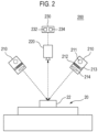
- FIG. 2 is a view schematically illustrating the configuration of a measurement device 200 for measuring a structure of an inspection object
- the measurement device 200 in FIG. 2 may include all the technical features of the measurement device 100 in FIG. 1 .
- the measurement device 200 includes an illumination unit 210, a imaging unit 220, and an image processing unit 230.
- the illumination unit 210 irradiates pattern light to the inspection target 22, which is a part of the inspection object 20, in order to measure the inspection target 22.
- the inspection object 20 is a printed circuit board
- the inspection target 22 is a solder formed on the printed circuit board or an electronic part mounted on the printed circuit board.
- the inspection object 20 and the inspection target 22 according to the present disclosure are not limited thereto, and may be any of products having a three-dimensional structure.
- the illumination unit 210 includes a light source 211 for emitting light, a grating element 212 for converting light from the light source 211 into the pattern light, a grating-transferring mechanism 213 for transferring the grating element 212 by a pitch, and a projection lens 214 for projecting the pattern light converted by the grating element 212 to the inspection target 22.
- the grating element 212 may be transferred by a predetermined distance (e.g., 2 ⁇ /N, where N is a natural number of 2 or more) using the grating-transferring mechanism 213, such as a piezo (PZT) actuator, for phase shift of the pattern light.
- two illumination units 210 may be provided.
- the illumination unit 210 according to the present disclosure is not limited thereto, and one illumination unit 210 or three or more illumination units 210 may be provided. If two or more illumination units 210 are provided, a plurality of illumination units 210 may be arranged to be spaced at a predetermined angle apart from each other along a circumferential direction or a virtual polygonal plane, or may be arranged to be spaced a constant distance apart from each other along the direction perpendicular to the inspection object 20.
- the imaging unit 220 may receive the light reflected by the inspection target 22, thereby acquiring image data of the inspection target 22.
- the imaging unit 220 may be implemented using a CCD (charge coupled device) camera or a CMOS (complementary metal oxide semiconductor) camera, but it is not limited thereto.
- the imaging unit 220 may be provided above the inspection object 20 in the vertical direction.
- the image processing unit 230 processes the image data acquired by the imaging unit 220, thereby generating measurement values of the structure of the inspection target 22. For example, the image processing unit 230 measures the width, length, height, area, volume, etc. of the inspection target 22 from the image data of the inspection target 22.
- the measurement values generated by the image processing unit 230 may be stored in the storage 232 of the image processing unit 230, or may be transmitted to the quality determination device 120 by the communication unit 234.
- FIG. 3 is a block diagram illustrating the detailed configuration of a quality determination device 300 for determining whether the an inspection object is good or defective.
- the quality determination device 300 in FIG. 3 may include all the technical features of the quality determination device 160 in FIG. 1 .
- the quality determination device 300 includes a communication unit 310, an input/output unit 320, a processing unit 330, and a database 340.
- the communication unit 310 may communicate with other devices, such as the measurement device 100, the determination review device 140, and the separate device 160 in FIG. 1 .
- the communication unit 310 subcomponents for communication with the above devices may be integrated into a single hardware device.
- the input/output unit 320 which interfaces with a user, includes a user input unit 322 and an output unit 324.
- the user input unit 322 may receive inputs in relation to quality determination from the user.
- the user input unit 322 may receive an input for adjusting the reference value used for quality determination, an input for displaying the result of the quality determination, an input for selecting one of the result of the quality determination, and the like.
- the user input unit 322 may include a keyboard, a mouse, a touchpad, a touch screen, and the like.
- the output unit 324 provides the user with outputs related to the quality determination.
- the output unit 324 may display the result of the quality determination of the inspection objects 20, the reference value used for quality determination, and the like.
- the output unit 324 may include a liquid crystal display (LCD), a light-emitting diode (LED) display, an organic light-emitting diode (OLED) display, and the like.
- the processing unit 330 may process data related to the quality determination.
- the processing unit 330 includes a quality determination unit 332, a determination result generation unit 334, and a determination reference adjustment unit 336.
- the database 340 which stores data related to the quality determination, includes a design value DB 342, a measurement value DB 344, an error value DB 346, a reference value DB 348, a determination result DB 350, and a determination review result DB 352.
- the design value DB 342 stores design values for all the inspection targets 22 of the inspection object 20. For example, if the inspection object 20 is a PCB, the width and length of a pad provided on the PCB, the volume and area of a solder placed on the pad, the height from an electronic component placed on the solder to the pad, and the like may be stored as design values in the design value DB 342.
- the measurement value DB 344 stores measurement values for all the inspection targets 22 of the inspection object 20.
- the measurement values stored in the measurement value DB 344 may correspond to the design values stored in the design value DB 342.
- the measurement values of the inspection object 20 may be generated by the measurement device 200 in FIG. 2 .
- the measurement values generated by the measurement device 200 may be stored in the measurement value DB 344 through the communication unit 234 of the measurement device 200 and the communication unit 310 of the quality determination device 300.
- the quality determination unit 332 may calculate error values of the measurement values with respect to the design values of the inspection target 22 of the inspection object 20.
- the quality determination unit 332 calculates, as an error value, the difference between the design value of the inspection target 22 of the inspection object 20, which is stored in the design value DB 342, and the measurement value of the inspection target 22 of the inspection object 20, which is stored in the measurement value DB 344.
- the calculated error values may be stored in the error value DB 346.
- the quality determination unit 332 may determine whether or not the structure of the inspection object 20 satisfies a predetermined criterion.
- the quality determination unit 332 may compare error values stored in the error value DB 346 with a reference value stored in the reference value DB 348, thereby determining whether or not the inspection object 20 is good or defective.
- the quality determination unit 332 may determine that the inspection object 20 is good if an error value for the inspection target 22 of the inspection object 20 is equal to or less than a reference value for the corresponding inspection target 20, and may determine that the inspection object 20 is defective if the error value exceeds the reference value.
- the quality determination unit 332 determines inspection object 20 having an error value of 0.6 mm for the length of the pad to be defective and determines inspection object 20 having an error value of 0.4 mm to be good.
- the quality determination results generated by the quality determination unit 332 may be stored in the determination result DB 350.
- the determination review result DB 352 stores the result of the determination review indicating whether or not there is an error in the quality determination of the quality determination unit 332 for the inspection target 22 of the inspection object 20. If an error occurs in the quality determination for the inspection target 22, "determination error" may be displayed as the result of the determination review for the corresponding inspection target 22.
- the determination error comprises a first type of error (Escape) in which the inspection target 22 determined to be good by the quality determination unit 332 is actually defective and a second type of error (False Call) in which the inspection target 22 determined to be defective by the quality determination unit 332 is actually good.
- the determination review results stored in the determination review result DB 352 may be generated by the determination review device 140 in FIG. 1 .
- the communication unit 310 may receive the determination review results generated by the determination review device 140, and may store the same in the determination review result DB 352.
- the distribution of the good error values, the range of the good error values, the distribution of the defective error values (if any), and the range of the defective error values (If any), which are estimated by the determination review device 140 may be stored in the determination review result DB 352 through the communication unit 310 of the quality determination device 300.
- the determination result generation unit 334 may generate an inspection result graph indicating the number of inspection objects depending on error values.
- the inspection result graph may be a two-dimensional graph, wherein the horizontal axis indicates error values and the vertical axis indicates the number of inspection objects 20 having corresponding error values.
- the determination result generation unit 334 may display a GUI (graphical user interface) object, which is movable by manipulation of the user, as a reference value on the inspection result graph.
- the GUI object indicating the reference value may have a shape such as a bar, an arrow, a line, a point, a square, or the like.
- the determination result generation unit 334 may display the result of the quality determination of the inspection objects 20 on the inspection result graph.
- the determination result generation unit 334 may display "good”, “warning", and “defective” as the result of the quality determination on the inspection result graph.
- the determination result generation unit 334 may display the area where error values are equal to or less than a reference value as "good” on the inspection result graph, and may display the area where error values exceed the reference value as "defective” on the inspection result graph.
- the determination result generation unit 334 may display a predetermined area where error values are close to the reference value as "warning" on the inspection result graph. In this case, the boundary of the area corresponding to "warning” may be displayed on the inspection result graph.
- the determination result generation unit 334 may display the number of inspection objects 20 corresponding to "good”, “warning", and “defective”, respectively, on the inspection result graph.
- the determination result generation unit 334 may display the review result for the result of the quality determination on the inspection result graph.
- the determination result generation unit 334 may display, as the result of the determination review, a first type of error (Escape) and a second type of error (False Call) on the inspection result graph.
- the determination result generation unit 334 displays the area including the inspection objects 20 that are actually determined to be good, among the areas where the error values exceed the reference value on the inspection result graph, as the first type of error (Escape).
- the determination result generation unit 334 displays the area including the inspection objects 20 that are actually determined to be defective, among the areas where the error values equal to or less than the reference value on the inspection result graph, as the second type of error (False Call).
- the determination error such as the first type of error and the second type of error, may be determined through accurate inspection by the determination review device 140.
- the determination review device 140 may include a device more accurately measuring the structure of the inspection object 20 or a device measuring the electrical characteristics of the inspection object 20.
- the determination review device 140 may more accurately measure the structural and electrical characteristics of the inspection object 20, thereby determining whether or not the inspection object 20 are actually good or defective.
- the determination review device 140 may identify the inspection objects 20 that are actually defective from among the inspection objects 20 determined to be good, and may identify the inspection objects 20 that are actually good from among the inspection objects 20 determined to be defective.
- the determination error may be determined through estimation from the distribution of error values by the determination review device 140.
- the determination review device 140 may determine one or more probability distribution curves fitting to the distribution of the error values of the inspection object 20, which is measured by the measurement device 100, may regard the probability distribution curve closest to the origin, among the determined probability distribution curves, as a distribution of the good error values, and may regard the remaining probability distribution curves (if any) as a distribution of the defective error values.
- the determination review device 140 may estimate the range of the good error values from the distribution of the good error values, and may estimate the range of the defective error values from the distribution of the defective error values (if any).
- the determination review device 140 may determine the inspection objects 20 in which determination error has occurred, among the inspection objects 20, based on the range of the good error values and the range of the defective error values (if any).
- the determination review device 140 may determine an error of the quality determination through estimation from the distribution of the error values, and the determination result generation unit 334 may identify the inspection objects 20 in which determination error has occurred based on the error of the quality determination determined by the determination review device 140, but the present disclosure is not limited thereto.
- the determination result generation unit 334 may directly determine the error of the quality determination through estimation from the distribution of the error values, and may identify the inspection objects 20 in which determination error has occurred.
- the determination result generation unit 334 may determine candidate reference value so as to update the reference value.
- the determination result generation unit 334 may determine at least one candidate reference value such that the number of inspection objects 20 in which determination error has occurred is reduced or minimized.
- the determination result generation unit 334 may determine the candidate reference value such that the area corresponding to the first type of error (Escape) or the second type of error (False Call) is reduced or eliminated by replacing the reference value with the candidate reference value.
- the determination result generation unit 334 may display one or more determined at least one candidate reference value on the inspection result graph.
- the at least one candidate reference value may be represented by points, lines, rectangles, arrows, and the like.
- the determination result generation unit 334 may determine the at least one candidate reference value based on the range of the good error value and the range of the defective error values (if any) of the inspection objects 20, which are estimated by the determination review device 140. If the range of the defective error values is provided, the determination result generation unit 334 is may determine the candidate reference value from among values equal to or greater than the maximum value of the range of the good error values and equal to or less than the minimum value of the range of the defective error values. If no the range of the defective error values is provided, the determination result generation unit 334 may determine the candidate reference value from among values equal to or greater than the maximum value of the range of the good error values.
- the user may select a predetermined area on the inspection result graph through the user input unit 322.
- the determination result generation unit 334 in response to a user input received through the user input unit 322, may enlarge the selected predetermined area, and may output the enlarged predetermined area through the output unit 324.
- the enlarged predetermined area may be output so as to overlap the inspection result graph.
- the determination result generation unit 334 may generate an inspection result list 333 that includes at least one of measurement values, error values, a result of the quality determination, and a result of determination error review for the inspection objects 20.
- the determination result generation unit 334 may output the inspection result graph and the inspection result list through the output unit 324.
- the user may identify the inspection result graph and inspection result list through the output unit 324.
- the user may select any one of the inspection objects 20 from the inspection result list through the user input unit 322.
- the determination result generation unit 334 may display the error values of the selected inspection object 20 on the inspection result graph.
- the error values of the selected inspection object 20 may be displayed in the form of a point, line, square, arrow, and the like. If no input for selecting the inspection object 20 is received from the user, an inspection object 20 that has most recently been determined to be good or to be defective may be automatically selected. In this case, the error values of the inspection object 20 that has most recently been determined to be good or to be defective may be displayed on the inspection result graph.
- the determination reference adjustment unit 336 may update the reference value according to an input received from the user through the user input unit 322.
- the determination reference adjustment unit 336 may receive, from the user, a graphical input for moving the location of a GUI object indicating the reference value on the inspection result graph. For example, the user may click on a movable bar-shaped GUI object indicating the reference value using a mouse as the user input unit 332, and may drag the same to a predetermined position on the inspection result graph.
- the determination reference adjustment unit 336 in response to the graphical input above, may update the reference value with a value corresponding to the dragged position.
- the determination reference adjustment unit 336 may receive, from the user, a graphical input for designating a specific position on the inspection result graph.
- the user may click on a specific position on the inspection result graph using a mouse as the user input unit 322.
- the determination reference adjustment unit 336 may update the reference value with a value corresponding to the clicked position in response to the graphical input above.
- the updated reference value may be stored in the reference value DB 348 by the determination reference adjustment unit 336.
- the quality determination unit 332 may redetermine inspection objects 20 to be good or to be defective based on the reference value updated by the determination reference adjustment unit 336. If the error values for the inspection target 22 of the inspection object 20 is equal to or less than the updated reference value, the quality determination unit 332 may redetermine that the inspection object 20 is good, and if the error value exceeds the updated reference value, the quality determination unit 332 may determine that the inspection object 20 is defective.
- the quality determination unit 332 may identify the inspection object 20, among the inspection objects 20, in which redetermination error has occurred.
- the quality determination unit 332 may identify the inspection objects 20 in which redetermination error has occurred based on redetermination results of the inspection objects 20 and the result of the determination reviews stored in the determination review result DB 352. For example, the quality determination unit 332 may determine that a first type of error (Escape) has occurred in the inspection object 20 that was redetermined to be good despite the fact that it is actually defective, and may determine that a second type of error (False Call) has occurred in the inspection object 20 that was redetermined to be defective despite the fact that it is actually good.
- a first type of error Escape
- False Call a second type of error
- the determination result generation unit 334 may display, on the inspection result graph, the reference value updated by the determination reference adjustment unit 336, the result of the quality redetermination using the updated reference value, and the result of the determination review for the result of the quality redetermination.
- the user may identify the inspection result graph output through the output unit 324, thereby confirming that the errors occurring in the quality redetermination using the updated reference value are reduced compared with the errors occurring in the quality determination using the reference value that is not updated.
- the quality determination device 300 may graphically indicate the result of the quality determination and a reference value for the inspection objects, and may adjust the reference value according to a graphical input of the user.
- the quality determination device 300 may perform quality redetermination for the inspection object based on the reset reference value, may check whether or not there is an error in the quality redetermination, and may graphically indicate the result of the quality redetermination and the result of the determination review thereof. As a result, the user may more efficiently and easily adjust the reference value used for quality determination of inspection object.
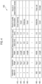
- FIG. 4 is a view illustrating an inspection result list 400 including determination error.
- the inspection result list 400 in FIG. 4 may be generated by the determination result generation unit 334 in FIG. 3 , and may be output through the output unit 324.
- the inspection result list 400 includes inspection result data 410, 420, 430, 440, 450, and 460 for each of a plurality of inspection objects.
- Each of the inspection result data 410, 420, 430, 440, 450, and 460 includes an ID of a corresponding inspection object, an inspection object ID, an inspection target, a measurement target, a measurement value, an error value, a result of a quality determination, and a result of a determination review.
- the inspection result data 410, 430 and 450 comprise measurement values obtained by measuring the width of "Pad 1" formed on the inspection object and error values obtained by differences between the measurement values and a design value of 10.0 mm. It is assumed that a reference value used for quality determination of the width of "Pad 1" is set to 0.5 mm. Referring to the inspection result data 410, the inspection object of ID "1" is determined to be good because the error value thereof is less than 0.5 mm. On the other hand, referring to the inspection result data 430 and 450, the inspection object of ID "2" and the inspection object of ID "459” are determined to be defective because error values thereof exceed 0.5 mm.
- the inspection object of ID "459” is determined to have the second type of error (False Call) as a result of quality determination review.
- the width of "Pad 1" in the inspection object of ID "459” is determined to be defective according to a predetermined determination criterion, but is actually good.
- the inspection result data 420, 440, and 460 include measurement values obtained by measuring the length of "Pad 1" provided on the inspection object and error values obtained by differences between the measurement values and a design value of 10.0 mm. It is assumed that a reference value used for quality determination of the length of "Pad 1" is set to 0.5 mm.
- the inspection objects of ID "1", “2", and “459” are determined to be good because the error values thereof are less than 0.5 mm.
- the inspection object of ID "459” is determined to have the first type of error (Escape) as a result of quality determination review.
- the length of "Pad 1" in the inspection object of ID "459” is determined to be good according to a predetermined determination criterion, but is actually defective.
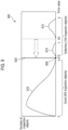
- FIG. 5 is a view illustrating an inspection result graph indicating a result of a quality determination and a review result of the quality determination.
- the inspection result graph 500 in FIG. 5 may be generated by the determination result generation unit 334, and may be output through the output unit 324 in FIG. 3 .
- the inspection result graph 500 in FIG. 5 may be generated in response to reception of an input for selecting any one of inspection result data (e.g., the inspection result data 450) from the inspection result list 400 in FIG. 4 through the user input unit 322.
- the horizontal axis of the inspection result graph 500 indicates error values, and the vertical axis thereof indicates the number of inspection objects.
- the inspection result graph 500 includes a curve 510 indicating the number of inspection objects having corresponding error values.
- the inspection result graph 500 may include a first reference value GUI 520 indicating a first reference value used for quality determination of the inspection objects and a second reference value GUI 530 indicating a second reference value used for determining the inspection objects corresponding to "warning", among the inspection objects determined to be "good".
- the second reference value may be set to 90% of the first reference value.
- the inspection result graph 500 may include a sample error value indicator 540 that indicates an error value "p" of any specific inspection object, such as an inspection object in which the user is particularly interested, among the inspection objects.
- the sample error value indicator 540 may indicate the error value of the inspection object selected from the inspection result list 400 in FIG. 4 .
- the sample error value indicator 540 may indicate the error value of the most recently inspected inspection object, among the inspection objects.
- the result of the quality determination and the result of the determination review may be displayed on the inspection result graph 500.
- the areas corresponding to "good”, “warning”, and “error”, respectively, as the result of the quality determination and the area corresponding to "defective” as the result of the determination review may be displayed on the inspection result graph 500.
- the number of inspection objects corresponding to "good”, “warning”, “error”, and “defective”, respectively may be displayed on the inspection result graph 500.
- 352 inspection objects having error values equal to or less than a first reference value "b" are determined to be "good”
- 107 inspection objects having error values exceeding the first reference value "b” are determined to be "defective".
- the error distribution of the 47 inspection objects having error values between the first reference value “b” and the value “c” is consistent with the natural error distribution of the 352 inspection objects determined to be good, so that 47 inspection objects having error values between the value "b” and the value "c", which have been determined to be “defective”, may be normal results of the given process, and may be actually good.
- the 47 inspection objects between the first reference value “b” and the value “c” may be determined to have the second type of error (false call).
- the user may select and examine a specific inspection object having an error value "p" between the first reference value "b” and the value "c".
- the first reference value is maintained to be the value "b"
- the error values will be naturally distributed between zero and the value "c" in the normal process.
- a significant number of products produced subsequently will continue to have the error values between the first reference value "b” and the value "c”, and will be determined to be "defective”. That is, in the example illustrated in FIG. 5 , if the production process itself is not erroneous, the first reference value for determining to be good and to be defective may be regarded as being set to be too strict without reflecting the characteristics of the natural error distribution in the production process.
- the inspection result graph 500 may include a candidate reference value indicator 550 indicating a candidate reference value to minimize the number of inspection objects in which determination error has occurred.
- the candidate reference value may be a candidate for a reference value, which minimizes the number of inspection objects (e.g., 0) determined to be error, and may be selected from the range of error values between the value "c" and the value "d".
- the candidate reference value indicator 550 is denoted by a dot in FIG. 5 , it is not limited thereto, and the candidate reference value indicator 550 may be displayed in any of various forms such as an arrow, a line, and a square.
- a single candidate reference value indicator 550 is displayed in FIG. 5 , it is not limited thereto, and a plurality of candidate reference value indicators may be displayed, or the candidate reference value indicator may be displayed in a range.
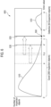
- FIG. 6 is a view illustrating an update of a reference value on an inspection result graph 600 according to an embodiment of the present disclosure.
- the inspection result graph 600 in FIG. 6 may be obtained from the inspection result graph 500 in FIG. 5 by updating the reference value thereof.
- the user may update the reference value on the inspection result graph 600 through the user input unit 322.
- the user may drag the first reference value GUI 520 to the position of the candidate reference value indicator 550 on the inspection result graph 600 using a mouse as the user input unit 322.
- the user may touch the position of the candidate reference value indicator 550 on the inspection result graph 600 using a touchpad.
- the position of the first reference value GUI 520 on the inspection result graph 600 is shifted by a graphical input through the user input unit 322.
- the first reference value may be updated as well. For example, as illustrated in FIG. 6 , the first reference value is updated from the value "b" to a value "b'".
- the position of the second reference value GUI 530 may also be shifted without a separate user input. For example, if the ratio of the second reference value to the first reference value is set to 90%, the second reference value GUI 530 may be moved to the right such that the second reference value becomes 90% of the updated first reference value. As illustrated in FIG. 6 , as the first reference value GUI 520 moves, the second reference value GUI 530 may also move such that the second reference value is updated from the value "a" to a value "a'" corresponding to 90% of the value "b'". The second reference value GUI 530 may be moved by a graphical input of the second reference value 530 on the inspection result graph 600 through the user input unit 322.
- the quality determination unit 332 may perform quality redetermination for the respective inspection objects based on the updated first and second reference values.
- the quality determination unit 332 may determine each inspection object to be "good” if the error value of the inspection object is equal to or less than the first reference value "b'", and may determine each inspection object to be "defective” if the error value of the inspection object exceeds the value "b'".
- the quality determination unit 332 may determine the inspection object to be "warning".
- the quality determination unit 332 may identify the inspection object in which a redetermination error has occurred, among the inspection objects.
- the quality determination results and the determination review results may be displayed on the inspection result graph 600.
- 399 inspection objects having error values equal to or less than the value "b'" are determined to be "good”
- 12 inspection objects having error values greater than the value "a'” and equal to or less than the value "b'” are determined to be "warning”
- 60 inspection objects having error values equal to or greater than the value "d” and equal to or less than the value "e” are determined to be "defective”.
- the quality determination error is minimized by updating the first reference value used as a criterion for quality determination of the inspection object.
- the first reference value GUI 520 is moved by a graphical input of the user, so that the quality determination device 300 may newly determine whether the inspection object is good or defective according to the updated reference value. That is, unlike the conventional process in which the user must visually check the measurement values one by one to determine a new reference value and must input the same in a numerical value, according to the present disclosure, the user is able to determine a new reference value while viewing the inspection result graph and is able to update the reference value by a graphical input. As a result, it is possible to change the first reference value by moving the first reference value GUI 520 while the determination error is visually displayed, thereby correcting the determination error quickly and conveniently. In addition, it is possible to newly determine whether the inspection object is good or defective based on the updated reference value, thereby assuring the user's convenience.
- FIG. 7 is a view illustrating an inspection result graph 700 in which a partial area is enlarged.
- the inspection result graph 700 in FIG. 7 is a graph indicating a result of the quality determination and a result of the determination review of the inspection objects, and may be the same as the inspection result graph 500 in FIG. 5 .
- the user may enlarge at least a portion of the inspection result graph 700, which is output through the output unit 324, using the user input unit 322.
- the user may select a predetermined area 710 on the inspection result graph 700 using a mouse as the user input unit 322.
- the determination result generation unit 334 may generate an enlarged graph 720 obtained by enlarging the predetermined area 710.
- the generated enlarged graph 720 may be output through the output unit 324.
- the enlarged graph 720 may be output separately from the inspection result graph 700, or may be output on the inspection result graph 700 so as to overlap the same.
- FIG. 8 is a view illustrating an inspection result graph 800 indicating a result of a quality determination and a review result of the quality determination.
- the inspection result graph 800 in FIG. 8 may be generated by the determination result generation unit 334, and may be output through the output unit 324 in FIG. 3 .
- the inspection result graph 800 in FIG. 8 may be generated in response to reception of an input for selecting any one of inspection result data (e.g., the inspection result data 460) from the inspection result list 400 in FIG. 4 through the user input unit 322.
- the inspection result graph 800 includes a curve 810 indicating the number of inspection objects having corresponding error values and a reference value GUI 820 indicating a reference value used for quality determination of the inspection object. As illustrated in FIG. 8 , 330 inspection objects having error values equal to or less than a first reference value "d" are determined to be "good”, and 129 inspection objects having error values between a value "e” and a value "f", which are greater than the first reference value "d”, are determined to be "defective”.
- the inspection result graph 800 may include a candidate reference value indicator 830 indicating a candidate reference value to minimize the number of inspection objects in which determination error has occurred.
- the candidate reference value may be a candidate for a reference value, which minimizes the number of inspection objects (e.g., 0) determined to be "error", and may be selected from the range of error values between the value "a" and the value "b".
- the candidate reference value indicator 830 is denoted by a dot in FIG. 8 , it is not limited thereto, and the candidate reference value indicator 830 may be displayed in any of various forms such as an arrow, a line, and a square.
- a single candidate reference value indicator 830 is displayed in FIG.
- the inspection result graph 800 may include a GUI indicating a reference value used for determining the inspection object corresponding to "warning", among the inspection objects determined to be "good”, and an indicator indicating error values of any one of the plurality of inspection objects.
- FIG. 9 is a view illustrating an inspection result graph 900 in which a reference value is updated according.
- the inspection result graph 900 in FIG. 9 may be obtained from the inspection result graph 800 in FIG. 8 by updating the reference value thereof.
- the user may update the reference value on the inspection result graph 900 through the user input unit 322.
- the user may drag the reference value GUI 820 to the position of the candidate reference value indicator 830 on the inspection result graph 900 using a mouse as the user input unit 322.
- the user may touch the position of the candidate reference value indicator 830 on the inspection result graph 900 using a touchpad.
- the position of the reference value GUI 820 is shifted on the inspection result graph 900 by a graphical input through the user input unit 322.
- the reference value may be updated as well. For example, as illustrated in FIG. 9 , the reference value is updated from the value "d" to a value "d'".
- the quality determination unit 332 may perform quality redetermination for the respective inspection objects based on the updated reference value.
- the quality determination unit 332 may determine each inspection object to be "good” if the error value of the inspection object is equal to or less than the reference value "d'", and may determine each inspection object to be "defective” if the error value of the inspection object exceeds the value "d'".
- the quality determination unit 332 may identify the inspection object in which a redetermination error has occurred, among the inspection objects.
- the result of the quality redetermination and the result of the redetermination review may be displayed on the inspection result graph 900.
- 305 inspection objects having error values equal to or less than the value "d'" are determined to be "good", and 154 inspection objects having error values exceeding the value "d'" are determined to be "defective”.
- the number of inspection objects with errors for quality determination is reduced from 25 in FIG. 8 to zero in FIG. 9 .
- the quality determination error is minimized by updating the reference value used as a criterion for quality determination of the inspection objects.
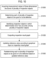
- FIG. 10 is a flowchart illustrating a method for adjusting a condition for determining a quality of inspection objects. At least some of the steps illustrated in FIG. 10 may be performed by the configurations illustrated in FIGS. 1 to 3 .
- the quality determination device 300 acquires measurement values of structures of a plurality of inspection objects.
- the measurement device 100 may irradiate light to the inspection object, may receive the light reflected from the inspection object, and may generate image data of the inspection object based on the received light.
- the measurement device 100 may generate measurement values by measuring the structure of the inspection object based on the image data.
- the quality determination device 300 may obtain the measurement values generated by the measurement device 100 through the communication unit 310.
- the quality determination unit 332 may perform quality determination for the respective inspection objects. For example, the quality determination unit 332 may determine whether the inspection object is good or defective by determining whether or not the measurement values obtained in step S1000 fall within predetermined ranges. The quality determination unit 332 may obtain error values between the measurement values and design values of the structure of the inspection object, and may compare the obtained error values with a predetermined reference value. The quality determination unit 332 may determine the inspection object having an error value equal to or less than the predetermined reference value to be "good", and may determine the inspection object having an error value exceeding the predetermined reference value to be "defective (NG)".
- NG defective
- the determination result generation unit 334 identifies the inspection object in which a determination error has occurred, among the plurality of inspection objects. For example, the determination result generation unit 334 identifies the inspection object in which a determination error has occurred, among the plurality of inspection objects, based on the quality determination results of the inspection objects obtained in step S1010 and the result of the determination review by the determination review device 140.
- the determination error includes a first error in which an inspection object determined to be "good” is actually identified “defective” and a second error in which an inspection object determined to be "defective" is actually identified to be "good".
- the determination review device 140 may determine a distribution of the good error values and a distribution of the defective error values (if any) based on the distribution of the error values of the inspection objects 20, which are measured by the measurement device 100, and may estimate a range of the good error values and a range of the defective error values (if any) from the distribution of the good error values and the distribution of the defective error values (if any).
- the determination review device 140 may identify the inspection object 20 in which a determination error has occurred, among the inspection objects 20, based on the range of the good error values and the range of the defective error values (if any).
- the determination result generation unit 334 may receive the result of the determination review from the determination review device 140, and may identify the inspection object 20 in which the determination error has occurred.
- the determination result generation unit 334 outputs inspection result graph.
- the determination result generation unit 334 generates an inspection result graph indicating the number of inspection objects according to error values.
- the inspection result graph may be a two-dimensional graph in which the horizontal axis indicates error values and the vertical axis indicates the number of inspection objects having corresponding error values, among the plurality of inspection objects.
- the determination result generation unit 334 may display, on the inspection result graph, a GUI object having a bar shape, which is movable by manipulation of a user, as a reference value.
- the determination result generation unit 334 may display "good", "warning", and "defective" as the result of the quality determination on the inspection result graph.
- the determination result generation unit 334 may display the review result of the quality determination results on the inspection result graph. In addition, the determination result generation unit 334 may determine at least one candidate reference value to minimize the number of one or more inspection objects in which the determination error has occurred, and may display the same on the inspection result graph.
- the candidate reference value may be determined based on the range of the good error values and the range of the defective error values (if any), which are estimated in step S1020. If the range of the defective error values is provided, the candidate reference value may be selected from among values equal to or greater than the maximum value of the range of the good error values and equal to or less than the minimum value of the range of the defective error values. If no the range of the defective error values is provided, the candidate reference value may be selected from among values equal to or greater than the maximum value of the range of the good error values.
- the determination reference adjustment unit 336 updates the reference value according to a graphical input on the inspection result graph.
- the user may provide a graphical input on the inspection result graph so as to reduce the number of one or more inspection objects in which the determination error has occurred. For example, the user may drag the GUI indicating the reference value to a predetermined position on the inspection result graph 600 using a mouse as the user input unit 322.
- the determination reference adjustment unit 336 updates the reference value with a predetermined value in response to the graphical input of the user (i.e., an input for moving the GUI indicating the reference value).
- the quality determination unit 332 performs quality redetermination for the respective inspection objects based on the updated reference value. For example, the quality determination unit 332 compares the reference value updated in step S1040 with the error values, thereby redetermining each of the plurality of inspection objects is good or defective. In addition, the quality determination unit 332 identifies the inspection object in which a redetermination error has occurred, among the plurality of inspection objects. In addition, the determination result generation unit 336 displays, on the inspection result graph, the updated reference value and the number of inspection objects in which the redetermination error has occurred.
- the computer-readable recording medium includes any kind of data storage devices that can be read by a computer system.
- the computer-readable recording medium may include ROM, RAM, CD-ROM, magnetic tapes, floppy disks, optical data storage devices, and the like.
- the computer-readable recording medium may be distributed over computer systems connected through a network so that the computer-readable codes may be stored and executed in a distribution manner. Further, functional programs, codes, and code segments may be easily inferred by programmers in the art to which the present disclosure pertains.
Landscapes
- Physics & Mathematics (AREA)
- General Physics & Mathematics (AREA)
- Health & Medical Sciences (AREA)
- Life Sciences & Earth Sciences (AREA)
- Chemical & Material Sciences (AREA)
- Analytical Chemistry (AREA)
- Biochemistry (AREA)
- General Health & Medical Sciences (AREA)
- Immunology (AREA)
- Pathology (AREA)
- Engineering & Computer Science (AREA)
- Computer Vision & Pattern Recognition (AREA)
- Signal Processing (AREA)
- General Engineering & Computer Science (AREA)
- Manufacturing & Machinery (AREA)
- Quality & Reliability (AREA)
- Automation & Control Theory (AREA)
- Investigating Materials By The Use Of Optical Means Adapted For Particular Applications (AREA)
- Testing Or Measuring Of Semiconductors Or The Like (AREA)
- Analysing Materials By The Use Of Radiation (AREA)
- Testing Of Individual Semiconductor Devices (AREA)
- Image Analysis (AREA)
- Image Processing (AREA)
Description
- The present disclosure relates to a method and a device for adjusting a condition for determining a quality of an inspection object.
- Manufacturers are making efforts to remove defective products during the production, assembly, intermediate process, and final assembly process. In such processes, manufacturers determine a quality of the product(that is, determine whether the product is good or defective (or no-good: NG) using various kinds of inspection systems.
- An inspection system may measure the structure of an inspection object and determine whether or not measurement values fall within a predetermined range, thereby determining whether the corresponding inspection object is good or defective. For example, the inspection system irradiates light to an inspection object and receives light reflected from the inspection object, thereby acquiring image data of the inspection object. In addition, the inspection system acquires measurement values of the inspection object based on the acquired image data and outputs an inspection result which is a result of determination whether the inspection object is good or defective (NG) based on the measurement values and a predetermined reference value.
- The inspection result obtained by the inspection system may comprise a determination error in which an inspection object, which is actually of good, is determined to be defective (False Call) or in which an inspection object, which is actually defective, is determined to be good (Escape). To remove such determination error, a reference value used for determining a quality of a product may be modified. However, existing inspection systems just display the measurement values of the inspection object in numbers on a display unit, and a user often inputs a reference value directly as well. Therefore, if the user desires to change the reference value, the user checks the measurement values displayed on the display unit, and directly inputs a new reference value every time.
EP 1264221 andUS2016/189055 are examples of a method for adjusting quality determination conditions. - The invention is described according to
independent method claim 1 and independent system claim 8. Additional aspects of the invention are described in the dependent claims. -
-
FIG. 1 is a view schematically illustrating an inspection system for determining an inspection object to be good or to be defective. -
FIG. 2 is a view schematically illustrating the configuration of a measurement device for measuring a structure of an inspection object. -
FIG. 3 is a block diagram illustrating the detailed configuration of a quality determination device for determining whether the an inspection object is good or. -
FIG. 4 is a view illustrating an inspection result list including determination error. -
FIG. 5 is a view illustrating an inspection result graph indicating a result of a quality determination and a review result of the quality determination. -
FIG. 6 is a view illustrating an update of a reference value on an inspection result graph. -
FIG. 7 is a view illustrating an inspection result graph in which a partial area is enlarged. -
FIG. 8 is a view illustrating an inspection result graph indicating a result of a quality determination and a review result of the quality determination. -
FIG. 9 is a view illustrating an inspection result graph in which a reference value is updated. -
FIG. 10 is a flowchart illustrating a method for adjusting a condition for determining a quality of inspection objects. - The term "unit" used herein means a software component or a hardware component, such as a field-programmable gate array (FPGA) and an application specific integrated circuit (ASIC). However, the "unit" is not limited to software and hardware. The "unit" may be configured to be provided in an addressable storage medium, or may be configured to run one or more processing units. Accordingly, for example, the "unit" may include components, such as software components, object-oriented software components, class components, and task components, as well as processing units, functions, attributes, procedures, subroutines, segments of program codes, drivers, firmware, micro-codes, circuits, data, databases, data structures, tables, arrays, and variables. Functions provided by the components and the "unit" may be combined into a smaller number of components, or may be further divided into additional components and "units."
- All technical or scientific terms used herein have meanings that are generally understood by a person skilled in the art to which the present disclosure pertains, unless otherwise specified. The terms used herein are selected for the purpose of clarifying the subject matter of the present disclosure, and are not intended to limit the scope of the present disclosure.
- A singular expression herein may include meanings of plurality, unless otherwise mentioned, and the same is applied to a singular expression stated in the claims.
- The terms "first", "second", and the like are used to distinguish between a plurality of components, and are not intended to limit the order or importance of the relevant components.
- The expressions "include", "have" and the like used herein should be understood as openended terms connoting the possibility of inclusion of other cases unless otherwise mentioned in a phrase or sentence including the expressions.
- The expression "based on" used herein is used to describe one or more factors that influences a decision, an action of determination, or an operation described in a phrase including the relevant expression, and this expression does not exclude additional factors influencing the decision, the action of determination, or the operation.
- When a certain component is described as "coupled to" or "connected to" another component herein, it should be understood that the certain component may be directly coupled or connected to another component, or that the certain component may be coupled or connected to another component via a new intervening component.
- Hereinafter, the present disclosure will be described with reference to the accompanying drawings. In the drawings, like components are indicated by like reference numerals, and repeated descriptions of the same components will be omitted.
-
FIG. 1 is a view schematically illustrating aninspection system 10 for determining an inspection object to be good or to be defective. - The
inspection system 10 may determine whether each of a plurality ofinspection objects 20 is good or defective, and may separate the plurality of inspection objects to be transferred to a good-product storage device 30 or a defective-product storage device 40 according to the determination result. Here, theinspection object 20 may be any product having a three-dimensional structure manufactured according to predetermined design criteria. For example, theinspection object 20 may be a printed circuit board (PCB) on which electronic components are mounted. - The
inspection system 10 may include ameasurement device 100, aquality determination device 120, adetermination review device 140, and aseparate device 160. Theinspection system 10 may also include a network 180 for connecting themeasurement device 100, thequality determination device 120, thedetermination review device 140, and theseparate device 160 to each other and performing communication therebetween. As illustrated inFIG. 1 , theinspection object 20 may be transferred to the good-product storage device 30 or the defective-product storage device 40 through themeasurement device 100, thedetermination review device 140, and theseparate device 160 along a direction of an arrow. - The
inspection system 10 may be installed at the end of a manufacturing stage for manufacturing theinspection object 20 or at the end of a processing stage for processing theinspection object 20. In this case, theinspection system 10 may determine whether the manufactured or processedinspection object 20 is manufactured according to predetermined design criteria. In addition, theinspection system 10 maytransfer inspection objects 20 determined to be good to the good-product storage device 30, and maytransfer inspection objects 20 determined to be defective to the defective-product storage device 40 according to a determination result. - The
measurement device 100 may generate measurement values by measuring the structure (e.g., a three-dimensional structure) of theinspection object 20. The themeasurement device 100 may measure the structure of theinspection object 20 using light. For example, themeasurement device 100 may irradiate a structured light to theinspection object 20, may receive light reflected from theinspection object 20, and may generate image data of theinspection object 20 based on the received light. In addition, themeasurement device 100 may generate measurement values by measuring the structure of theinspection object 20 based on the image data. The measurement values generated by themeasurement device 100 may be transmitted to thequality determination device 120 through the network 180. The configuration and operation of themeasurement device 100 will be described in more detail with reference toFIG. 2 . - The
quality determination device 120 may determine whether theinspection object 20 is good or defective. Thequality determination device 120 may determine whether theinspection object 20 is good or defective by determining whether or not the measurement value generated by themeasurement device 100 fall within a predetermined range. The thequality determination device 120 may calculate error values between design values and the measurement values of the structure of theinspection object 20. Thequality determination device 120 may determine that theinspection object 20 having error values equal to or less than a predetermined reference value to be good, and may determine that theinspection object 20 having error values exceeding the predetermined reference value to be defective (NG). - The
quality determination device 120 may determine some of theinspection objects 20 having error values equal to or less than the predetermined reference value (i.e., some of theinspection objects 20 determined to be good) to be "warning". For example, if the error values of theinspection object 20 fall within a predetermined range close to the predetermined reference value, thequality determination device 120 may determine thecorresponding inspection object 20 to be "warning". - The
determination review device 140 may determine whether or not there is an error in the quality determination of theinspection object 20 performed by thequality determination device 120. For example, theinspection object 20 determined to be good by thequality determination device 120 may actually be defective (Escape). In addition, theinspection object 20 determined to be defective by thequality determination device 120 may actually be good (False Call). Such a determination error may occur in thequality determination device 120 when the reference value used for quality determination is not properly set. For example, if a predetermined reference value to be compared with the error values is set to be high, thequality determination device 120 may determine aninspection object 20, which is actually defective, to be good, and thedetermination review device 140 may determine that an error has occurred in the determination of theinspection object 20 which is actually defective, and is determined to be good. In addition, if a predetermined reference value to be compared with the error values is set to be low, thequality determination device 120 may determine aninspection object 20, which is actually good, to be defective, and thedetermination review device 140 may determine that an error has occurred in the determination of theinspection object 20 which is actually good and is determined to be defective. - The
determination review device 140 may be implemented using a device determining whether or not the quality of theinspection object 20 is actually good or defective. For example, thedetermination review device 140 may include a device more accurately measuring the structure of theinspection object 20. As another example, thedetermination review device 140 may include a device checking an electrical characteristics of theinspection object 20. - The
determination review device 140 may determine whether or not there is a determination error in some of the inspection objects 20 that are determined to be good or to be defective byquality determination device 120. For example, thedetermination review device 140 may determine whether or not there is a determination error in theinspection object 20 that is determined to be "warning" or "defective" by thequality determination device 120. In this case, the efficiency may be improved as compared to the case of determining the determination error in all inspection objects. - The
determination review device 140 may also determine whether or not there are determination error in all inspection objects 20 that is determined to be good or defective by thequality determination device 120. In this case, accuracy may be improved compared to the case of determining the determination error of some inspection objects. A review result of thedetermination review device 140 may be transmitted to thequality determination device 120 through the network 180. - The
determination review device 140, based on a distribution of the measured error values, may estimate a range of good error values of inspection objects 20 determined to be good, and may further estimate a range of defective error values inspection objects 20 determined to be defective. - Error values of the physical properties of products produced according to a specific manufacturing process may have a constant probability distribution. The error values of inspection objects 20, which are produced through a given process and are determined to be good, may have a distribution of good error values, which is, for example, expressed as a Gamma distribution curve. The error values of inspection objects 20 which are determined to be defective due to problems other than the process may have a distribution of defective error values, which is, for example, expressed as a Normal distribution curve.
- Using the above, the
determination review device 140 may determine at least one probability distribution curve that most closely fits the distribution of the measured error values, may regard a probability distribution curve that is closest to the origin, among the determined probability distribution curves, as the distribution of the good error values, and may regard the remaining probability distribution curves (if any) as the distribution of the defective error values. - Meanwhile, vertical axes of graphs of a distribution curve of the good error values and a distribution curve of the defective error values denote the number of inspection object samples, which is a natural number. Thus, it may be possible to consider that one or more inspection object samples exist stochastically only in a range of the horizontal axis in which the vertical axis value of the graph is 1 or more and that if a value is out of the range of the horizontal axis above, an inspection object sample of less than 1 exists (i.e., no inspection object sample exists). In some cases, the user may consider only the range of error values in which the number of inspection object samples is a predetermined number or more as a meaningful range of the error values. In some cases, the user may consider only the range of error values, which includes the inspection object samples of a predetermined percentage of the inspected inspection object samples (e.g., the inspection object samples of 99.5% in order from the smallest error value to the largest error value), as a meaningful range of the error values.
- According to these observations, a range of good error values or a range of defective error values, which is considered to be meaningful by the user, may be estimated from the distribution curve of the good error values or the distribution curve of the defective error values. The meaningful distribution of the defective error values may not be obtained depending on the situation, and thus the meaningful range of defective error values may not be estimated.
- More specifically, the
determination review device 140 may estimate a distribution of the good error values using a predetermined probability distribution function from the distribution of a given sample error values, and may further estimate a distribution of the defective error values as necessary. In this case, thedetermination review device 140 may estimate a range of good error values in which one or more samples exist from the distribution of the good error values, and may estimate a range of the defective error values in which one or more samples exist from the distribution of the defective error values (if any). - If the estimated range of the good error values and range of the defective error values partially overlap each other, the
determination review device 140 may re-estimate a reduced range of the good error values and a reduced range of the defective error values, respectively, in consideration of the area where the distribution of the good error values and the distribution of the defective error values overlap each other. - If two or more distributions of the defective error values are estimated, the
determination review device 140 may re-estimate an integrated range of the defective error value encompassing ranges of the defective error values, which are estimated from the respective distributions of the defective error values. - The
determination review device 140 may determine whether or not there is an error in the quality determination of theinspection object 20 performed by thequality determination device 120 based on the estimated range of the good error values and further based on (if any) the estimated range of the defective error values. - For example, if the reference value of quality determination falls within the range of the good error values, and if an error value of a
certain inspection object 20 is greater than the reference value but is within the range of the good error values, thedetermination review device 140 may determine that there is a second type of error (false call) in which theinspection object 20 which is determined to be defective due to the reference value but is actually good, and may determine that the current reference value is too strict. - For example, if the reference value of quality determination falls within or exceeds the range of the defective error values, and if an error value of a
certain inspection object 20 is less than the reference value but is within the range of the defective error values, thedetermination review device 140 may determine that there is a first type of error (escape) in which theinspection object 20 which is determined to be good due to the reference value but is actually defective, and may determine that the reference value is too loose. - Accordingly, the
determination review device 140 may determine the number of inspection objects in which a determination error has occurred by means of the number of inspection objects 20 having error values, which are within the range of the good error values and greater than a reference value, in the case where the reference value of quality determination falls within the range of the good error values or by means of the number of inspection objects 20 having error values, which are within the range of the defective error values and less than a reference value, in the case where the reference value of quality determination falls within the range of defective error values or exceeds the same. - The determination result of the
determination review device 140 may be transmitted to thequality determination device 120 through the network 180. In addition, the distribution of the good error values and the range of the good error values, which are estimated by thedetermination review device 140, may also be transmitted to thequality determination device 120 via the network 180. Additionally, the distribution of the defective error values and the range of the defective error values, which are estimated by thedetermination review device 140, may also be transmitted to thequality determination device 120 through the network 180. - As described above, the
determination review device 140 may identify inspection objects 20 that are strongly expected to have the determination error from the distributions of error values detected in the samples in the early stages of production even though the samples determined to be defective are not actually re-inspected accurately, and may further determine an appropriateness of the current reference value. - The
quality determination device 120 may adjust the condition for determining the quality of theinspection object 20 such that the number of inspection objects 20 determined to have determination error by thedetermination review device 140 is reduced. Thequality determination device 120 may update the reference value to be compared with the error values based on the results of the quality determination of theinspection object 20 generated by thequality determination device 120 and the result of the determination review of theinspection object 20 generated by thedetermination review device 140. For example, if thedetermination review device 140 determines that determination error (False call) has occurred in at least a part of inspection objects 20, thequality determination device 120 may increase the reference value to be compared with the error values. In addition, if it is determined by thedetermination review device 140 that determination error (Escape) has occurred in at least a part of inspection objects 20, thequality determination device 120 may reduce the reference value to be compared with the error values. - The
quality determination device 120 may update the reference value to be compared with the error values according to user input. Thequality determination device 120 may graphically display the result of the quality determination, the result of the determination review, and the reference value for inspection objects 20. The user may provide a graphical input to thequality determination device 120 to adjust the reference value such that the number of inspection objects in which the determination error has occurred is reduced based on the graphically displayed result of the quality determination and the result of the determination review. Thequality determination device 120 may update the reference value in response to the graphical input of the user. - The
quality determination device 120 may compare the updated reference value with the error values, thereby redetermining whether or not the quality of theinspection object 20 is good or defective. In addition, thequality determination device 120 may identify whether or not there in an error in the redetermination result of theinspection object 20 based on the result of the determination review generated by thedetermination review device 140, which indicate whether theinspection object 20 is actually good or defective. Accordingly, thequality determination device 120 may graphically display the result or the quality redetermination of the inspection objects 20, the updated reference value, and the number of inspection objects in which the redetermination error has occurred. - The
quality determination device 120 may be implemented using a computing device, such as, a server computer, a personal computer, a laptop computer, a smart phone, or a tablet PC. The configuration and operation of thequality determination device 120 will be described in more detail with reference toFIGS. 3 to 10 . - The
separate device 160 may separate the inspection objects 20 to be transferred to the good-product storage device 30 or the defective-product storage device 40. Theseparate device 160 may transfer inspection objects 20 determined to be good and inspection objects 20 determined to be defective to the good-product storage device 30 and the defective-product storage device 40, respectively, based on the redetermination results by thequality determination device 120. - The network 180 enables connections and communications between the
measurement device 100, thequality determination device 120, thedetermination review device 140, and theseparate device 160. The network 180 may be implemented using a wired network, such as a local area network (LAN), a wide area network (WAN), a value added network (VAN), or the like, or using a wireless network, such as a mobile radio communication network, a satellite communication network, Bluetooth, the wireless broadband Internet (Wibro), high-speed downlink packet access (HSDPA), or the like. - Although the respective devices of the
inspection system 10 are illustrated as separate configurations inFIG. 1 , the present disclosure is not limited thereto, and at least some of the configurations of any one of thequality determination device 120, thedetermination review device 140, and theseparate device 160 may be integrated into other devices. At least some configurations of thedetermination review device 140 may be integrated into thequality determination device 120. For example, the configuration of thedetermination review device 140 for determining an error of the quality determination through estimation from a distribution of error values may be implemented as thequality determination device 120. -
FIG. 2 is a view schematically illustrating the configuration of ameasurement device 200 for measuring a structure of an inspection object, Themeasurement device 200 inFIG. 2 may include all the technical features of themeasurement device 100 inFIG. 1 . As illustrated inFIG. 2 , themeasurement device 200 includes anillumination unit 210, aimaging unit 220, and animage processing unit 230. - The
illumination unit 210 irradiates pattern light to theinspection target 22, which is a part of theinspection object 20, in order to measure theinspection target 22. For example, theinspection object 20 is a printed circuit board, and theinspection target 22 is a solder formed on the printed circuit board or an electronic part mounted on the printed circuit board. However, theinspection object 20 and theinspection target 22 according to the present disclosure are not limited thereto, and may be any of products having a three-dimensional structure. - The
illumination unit 210 includes alight source 211 for emitting light, agrating element 212 for converting light from thelight source 211 into the pattern light, a grating-transferringmechanism 213 for transferring thegrating element 212 by a pitch, and aprojection lens 214 for projecting the pattern light converted by thegrating element 212 to theinspection target 22. For example, thegrating element 212 may be transferred by a predetermined distance (e.g., 2π/N, where N is a natural number of 2 or more) using the grating-transferringmechanism 213, such as a piezo (PZT) actuator, for phase shift of the pattern light. - As illustrated in
FIG. 2 , twoillumination units 210 may be provided. However, theillumination unit 210 according to the present disclosure is not limited thereto, and oneillumination unit 210 or three ormore illumination units 210 may be provided. If two ormore illumination units 210 are provided, a plurality ofillumination units 210 may be arranged to be spaced at a predetermined angle apart from each other along a circumferential direction or a virtual polygonal plane, or may be arranged to be spaced a constant distance apart from each other along the direction perpendicular to theinspection object 20. - The
imaging unit 220 may receive the light reflected by theinspection target 22, thereby acquiring image data of theinspection target 22. Theimaging unit 220 may be implemented using a CCD (charge coupled device) camera or a CMOS (complementary metal oxide semiconductor) camera, but it is not limited thereto. Theimaging unit 220 may be provided above theinspection object 20 in the vertical direction. - The
image processing unit 230 processes the image data acquired by theimaging unit 220, thereby generating measurement values of the structure of theinspection target 22. For example, theimage processing unit 230 measures the width, length, height, area, volume, etc. of theinspection target 22 from the image data of theinspection target 22. The measurement values generated by theimage processing unit 230 may be stored in thestorage 232 of theimage processing unit 230, or may be transmitted to thequality determination device 120 by thecommunication unit 234. -
FIG. 3 is a block diagram illustrating the detailed configuration of aquality determination device 300 for determining whether the an inspection object is good or defective. Thequality determination device 300 inFIG. 3 may include all the technical features of thequality determination device 160 inFIG. 1 . As illustrated inFIG. 3 , thequality determination device 300 includes acommunication unit 310, an input/output unit 320, aprocessing unit 330, and adatabase 340. - The
communication unit 310 may communicate with other devices, such as themeasurement device 100, thedetermination review device 140, and theseparate device 160 inFIG. 1 . In thecommunication unit 310, subcomponents for communication with the above devices may be integrated into a single hardware device. - The input/
output unit 320, which interfaces with a user, includes auser input unit 322 and anoutput unit 324. Theuser input unit 322 may receive inputs in relation to quality determination from the user. For example, theuser input unit 322 may receive an input for adjusting the reference value used for quality determination, an input for displaying the result of the quality determination, an input for selecting one of the result of the quality determination, and the like. Theuser input unit 322 may include a keyboard, a mouse, a touchpad, a touch screen, and the like. - The
output unit 324 provides the user with outputs related to the quality determination. For example, theoutput unit 324 may display the result of the quality determination of the inspection objects 20, the reference value used for quality determination, and the like. Theoutput unit 324 may include a liquid crystal display (LCD), a light-emitting diode (LED) display, an organic light-emitting diode (OLED) display, and the like. - The
processing unit 330 may process data related to the quality determination. Theprocessing unit 330 includes aquality determination unit 332, a determinationresult generation unit 334, and a determinationreference adjustment unit 336. In addition, thedatabase 340, which stores data related to the quality determination, includes adesign value DB 342, ameasurement value DB 344, anerror value DB 346, areference value DB 348, adetermination result DB 350, and a determinationreview result DB 352. - The
design value DB 342 stores design values for all the inspection targets 22 of theinspection object 20. For example, if theinspection object 20 is a PCB, the width and length of a pad provided on the PCB, the volume and area of a solder placed on the pad, the height from an electronic component placed on the solder to the pad, and the like may be stored as design values in thedesign value DB 342. - The
measurement value DB 344 stores measurement values for all the inspection targets 22 of theinspection object 20. The measurement values stored in themeasurement value DB 344 may correspond to the design values stored in thedesign value DB 342. The measurement values of theinspection object 20 may be generated by themeasurement device 200 inFIG. 2 . The measurement values generated by themeasurement device 200 may be stored in themeasurement value DB 344 through thecommunication unit 234 of themeasurement device 200 and thecommunication unit 310 of thequality determination device 300. - The
quality determination unit 332 may calculate error values of the measurement values with respect to the design values of theinspection target 22 of theinspection object 20. Thequality determination unit 332 calculates, as an error value, the difference between the design value of theinspection target 22 of theinspection object 20, which is stored in thedesign value DB 342, and the measurement value of theinspection target 22 of theinspection object 20, which is stored in themeasurement value DB 344. The calculated error values may be stored in theerror value DB 346. - The
quality determination unit 332 may determine whether or not the structure of theinspection object 20 satisfies a predetermined criterion. Thequality determination unit 332 may compare error values stored in theerror value DB 346 with a reference value stored in thereference value DB 348, thereby determining whether or not theinspection object 20 is good or defective. Thequality determination unit 332 may determine that theinspection object 20 is good if an error value for theinspection target 22 of theinspection object 20 is equal to or less than a reference value for thecorresponding inspection target 20, and may determine that theinspection object 20 is defective if the error value exceeds the reference value. For example, if the reference value for the length of a pad of theinspection object 20 is set to 0.5 mm, thequality determination unit 332 determinesinspection object 20 having an error value of 0.6 mm for the length of the pad to be defective and determinesinspection object 20 having an error value of 0.4 mm to be good. The quality determination results generated by thequality determination unit 332 may be stored in thedetermination result DB 350. - The determination
review result DB 352 stores the result of the determination review indicating whether or not there is an error in the quality determination of thequality determination unit 332 for theinspection target 22 of theinspection object 20. If an error occurs in the quality determination for theinspection target 22, "determination error" may be displayed as the result of the determination review for thecorresponding inspection target 22. The determination error comprises a first type of error (Escape) in which theinspection target 22 determined to be good by thequality determination unit 332 is actually defective and a second type of error (False Call) in which theinspection target 22 determined to be defective by thequality determination unit 332 is actually good. - The determination review results stored in the determination
review result DB 352 may be generated by thedetermination review device 140 inFIG. 1 . Thecommunication unit 310 may receive the determination review results generated by thedetermination review device 140, and may store the same in the determinationreview result DB 352. In addition, the distribution of the good error values, the range of the good error values, the distribution of the defective error values (if any), and the range of the defective error values (If any), which are estimated by thedetermination review device 140, may be stored in the determinationreview result DB 352 through thecommunication unit 310 of thequality determination device 300. - The determination
result generation unit 334 may generate an inspection result graph indicating the number of inspection objects depending on error values. The inspection result graph may be a two-dimensional graph, wherein the horizontal axis indicates error values and the vertical axis indicates the number of inspection objects 20 having corresponding error values. In addition, the determinationresult generation unit 334 may display a GUI (graphical user interface) object, which is movable by manipulation of the user, as a reference value on the inspection result graph. For example, the GUI object indicating the reference value may have a shape such as a bar, an arrow, a line, a point, a square, or the like. - The determination
result generation unit 334 may display the result of the quality determination of the inspection objects 20 on the inspection result graph. The determinationresult generation unit 334 may display "good", "warning", and "defective" as the result of the quality determination on the inspection result graph. For example, the determinationresult generation unit 334 may display the area where error values are equal to or less than a reference value as "good" on the inspection result graph, and may display the area where error values exceed the reference value as "defective" on the inspection result graph. In addition, the determinationresult generation unit 334 may display a predetermined area where error values are close to the reference value as "warning" on the inspection result graph. In this case, the boundary of the area corresponding to "warning" may be displayed on the inspection result graph. In addition, according to an embodiment, the determinationresult generation unit 334 may display the number of inspection objects 20 corresponding to "good", "warning", and "defective", respectively, on the inspection result graph. - The determination
result generation unit 334 may display the review result for the result of the quality determination on the inspection result graph. The determinationresult generation unit 334 may display, as the result of the determination review, a first type of error (Escape) and a second type of error (False Call) on the inspection result graph. For example, the determinationresult generation unit 334 displays the area including the inspection objects 20 that are actually determined to be good, among the areas where the error values exceed the reference value on the inspection result graph, as the first type of error (Escape). In addition, the determinationresult generation unit 334 displays the area including the inspection objects 20 that are actually determined to be defective, among the areas where the error values equal to or less than the reference value on the inspection result graph, as the second type of error (False Call). - The determination error, such as the first type of error and the second type of error, may be determined through accurate inspection by the
determination review device 140. Thedetermination review device 140 may include a device more accurately measuring the structure of theinspection object 20 or a device measuring the electrical characteristics of theinspection object 20. Thedetermination review device 140 may more accurately measure the structural and electrical characteristics of theinspection object 20, thereby determining whether or not theinspection object 20 are actually good or defective. As a result, thedetermination review device 140 may identify the inspection objects 20 that are actually defective from among the inspection objects 20 determined to be good, and may identify the inspection objects 20 that are actually good from among the inspection objects 20 determined to be defective. - The determination error may be determined through estimation from the distribution of error values by the
determination review device 140. Thedetermination review device 140 may determine one or more probability distribution curves fitting to the distribution of the error values of theinspection object 20, which is measured by themeasurement device 100, may regard the probability distribution curve closest to the origin, among the determined probability distribution curves, as a distribution of the good error values, and may regard the remaining probability distribution curves (if any) as a distribution of the defective error values. Thedetermination review device 140 may estimate the range of the good error values from the distribution of the good error values, and may estimate the range of the defective error values from the distribution of the defective error values (if any). In addition, thedetermination review device 140 may determine the inspection objects 20 in which determination error has occurred, among the inspection objects 20, based on the range of the good error values and the range of the defective error values (if any). - The
determination review device 140 may determine an error of the quality determination through estimation from the distribution of the error values, and the determinationresult generation unit 334 may identify the inspection objects 20 in which determination error has occurred based on the error of the quality determination determined by thedetermination review device 140, but the present disclosure is not limited thereto. For example, the determinationresult generation unit 334 may directly determine the error of the quality determination through estimation from the distribution of the error values, and may identify the inspection objects 20 in which determination error has occurred. - The determination
result generation unit 334 may determine candidate reference value so as to update the reference value. The determinationresult generation unit 334 may determine at least one candidate reference value such that the number of inspection objects 20 in which determination error has occurred is reduced or minimized. For example, the determinationresult generation unit 334 may determine the candidate reference value such that the area corresponding to the first type of error (Escape) or the second type of error (False Call) is reduced or eliminated by replacing the reference value with the candidate reference value. The determinationresult generation unit 334 may display one or more determined at least one candidate reference value on the inspection result graph. For example, the at least one candidate reference value may be represented by points, lines, rectangles, arrows, and the like. - The determination
result generation unit 334 may determine the at least one candidate reference value based on the range of the good error value and the range of the defective error values (if any) of the inspection objects 20, which are estimated by thedetermination review device 140. If the range of the defective error values is provided, the determinationresult generation unit 334 is may determine the candidate reference value from among values equal to or greater than the maximum value of the range of the good error values and equal to or less than the minimum value of the range of the defective error values. If no the range of the defective error values is provided, the determinationresult generation unit 334 may determine the candidate reference value from among values equal to or greater than the maximum value of the range of the good error values. - The user may select a predetermined area on the inspection result graph through the
user input unit 322. The determinationresult generation unit 334, in response to a user input received through theuser input unit 322, may enlarge the selected predetermined area, and may output the enlarged predetermined area through theoutput unit 324. For example, the enlarged predetermined area may be output so as to overlap the inspection result graph. - The determination
result generation unit 334 may generate an inspection result list 333 that includes at least one of measurement values, error values, a result of the quality determination, and a result of determination error review for the inspection objects 20. The determinationresult generation unit 334 may output the inspection result graph and the inspection result list through theoutput unit 324. The user may identify the inspection result graph and inspection result list through theoutput unit 324. - The user may select any one of the inspection objects 20 from the inspection result list through the
user input unit 322. In response to the user input received through theuser input unit 322, the determinationresult generation unit 334 may display the error values of the selectedinspection object 20 on the inspection result graph. For example, the error values of the selectedinspection object 20 may be displayed in the form of a point, line, square, arrow, and the like. If no input for selecting theinspection object 20 is received from the user, aninspection object 20 that has most recently been determined to be good or to be defective may be automatically selected. In this case, the error values of theinspection object 20 that has most recently been determined to be good or to be defective may be displayed on the inspection result graph. - The determination
reference adjustment unit 336 may update the reference value according to an input received from the user through theuser input unit 322. The determinationreference adjustment unit 336 may receive, from the user, a graphical input for moving the location of a GUI object indicating the reference value on the inspection result graph. For example, the user may click on a movable bar-shaped GUI object indicating the reference value using a mouse as theuser input unit 332, and may drag the same to a predetermined position on the inspection result graph. In this case, the determinationreference adjustment unit 336, in response to the graphical input above, may update the reference value with a value corresponding to the dragged position. The determinationreference adjustment unit 336 may receive, from the user, a graphical input for designating a specific position on the inspection result graph. For example, the user may click on a specific position on the inspection result graph using a mouse as theuser input unit 322. In this case, the determinationreference adjustment unit 336 may update the reference value with a value corresponding to the clicked position in response to the graphical input above. The updated reference value may be stored in thereference value DB 348 by the determinationreference adjustment unit 336. - The
quality determination unit 332 may redetermine inspection objects 20 to be good or to be defective based on the reference value updated by the determinationreference adjustment unit 336. If the error values for theinspection target 22 of theinspection object 20 is equal to or less than the updated reference value, thequality determination unit 332 may redetermine that theinspection object 20 is good, and if the error value exceeds the updated reference value, thequality determination unit 332 may determine that theinspection object 20 is defective. - In addition, the
quality determination unit 332 may identify theinspection object 20, among the inspection objects 20, in which redetermination error has occurred. Thequality determination unit 332 may identify the inspection objects 20 in which redetermination error has occurred based on redetermination results of the inspection objects 20 and the result of the determination reviews stored in the determinationreview result DB 352. For example, thequality determination unit 332 may determine that a first type of error (Escape) has occurred in theinspection object 20 that was redetermined to be good despite the fact that it is actually defective, and may determine that a second type of error (False Call) has occurred in theinspection object 20 that was redetermined to be defective despite the fact that it is actually good. - The determination
result generation unit 334 may display, on the inspection result graph, the reference value updated by the determinationreference adjustment unit 336, the result of the quality redetermination using the updated reference value, and the result of the determination review for the result of the quality redetermination. The user may identify the inspection result graph output through theoutput unit 324, thereby confirming that the errors occurring in the quality redetermination using the updated reference value are reduced compared with the errors occurring in the quality determination using the reference value that is not updated. - As described above, the
quality determination device 300 may graphically indicate the result of the quality determination and a reference value for the inspection objects, and may adjust the reference value according to a graphical input of the user. In addition, thequality determination device 300 may perform quality redetermination for the inspection object based on the reset reference value, may check whether or not there is an error in the quality redetermination, and may graphically indicate the result of the quality redetermination and the result of the determination review thereof. As a result, the user may more efficiently and easily adjust the reference value used for quality determination of inspection object. -
FIG. 4 is a view illustrating aninspection result list 400 including determination error. Theinspection result list 400 inFIG. 4 may be generated by the determinationresult generation unit 334 inFIG. 3 , and may be output through theoutput unit 324. - As illustrated in
FIG. 4 , theinspection result list 400 includesinspection result data inspection result data - The
inspection result data Pad 1" formed on the inspection object and error values obtained by differences between the measurement values and a design value of 10.0 mm. It is assumed that a reference value used for quality determination of the width of "Pad 1" is set to 0.5 mm. Referring to theinspection result data 410, the inspection object of ID "1" is determined to be good because the error value thereof is less than 0.5 mm. On the other hand, referring to theinspection result data Pad 1" in the inspection object of ID "459" is determined to be defective according to a predetermined determination criterion, but is actually good. - The
inspection result data Pad 1" provided on the inspection object and error values obtained by differences between the measurement values and a design value of 10.0 mm. It is assumed that a reference value used for quality determination of the length of "Pad 1" is set to 0.5 mm. Referring to theinspection result data 410, the inspection objects of ID "1", "2", and "459" are determined to be good because the error values thereof are less than 0.5 mm. Among the inspection objects above, the inspection object of ID "459" is determined to have the first type of error (Escape) as a result of quality determination review. For example, the length of "Pad 1" in the inspection object of ID "459" is determined to be good according to a predetermined determination criterion, but is actually defective. -
FIG. 5 is a view illustrating an inspection result graph indicating a result of a quality determination and a review result of the quality determination. Theinspection result graph 500 inFIG. 5 may be generated by the determinationresult generation unit 334, and may be output through theoutput unit 324 inFIG. 3 . Theinspection result graph 500 inFIG. 5 may be generated in response to reception of an input for selecting any one of inspection result data (e.g., the inspection result data 450) from theinspection result list 400 inFIG. 4 through theuser input unit 322. - As illustrated in
FIG. 5 , the horizontal axis of theinspection result graph 500 indicates error values, and the vertical axis thereof indicates the number of inspection objects. Theinspection result graph 500 includes acurve 510 indicating the number of inspection objects having corresponding error values. In addition, theinspection result graph 500 may include a firstreference value GUI 520 indicating a first reference value used for quality determination of the inspection objects and a secondreference value GUI 530 indicating a second reference value used for determining the inspection objects corresponding to "warning", among the inspection objects determined to be "good". For example, the second reference value may be set to 90% of the first reference value. - In addition, the
inspection result graph 500 may include a sampleerror value indicator 540 that indicates an error value "p" of any specific inspection object, such as an inspection object in which the user is particularly interested, among the inspection objects. For example, the sampleerror value indicator 540 may indicate the error value of the inspection object selected from theinspection result list 400 inFIG. 4 . As another example, the sampleerror value indicator 540 may indicate the error value of the most recently inspected inspection object, among the inspection objects. - The result of the quality determination and the result of the determination review may be displayed on the
inspection result graph 500. The areas corresponding to "good", "warning", and "error", respectively, as the result of the quality determination and the area corresponding to "defective" as the result of the determination review may be displayed on theinspection result graph 500. In addition, the number of inspection objects corresponding to "good", "warning", "error", and "defective", respectively, may be displayed on theinspection result graph 500. As illustrated inFIG. 5 , 352 inspection objects having error values equal to or less than a first reference value "b" are determined to be "good", and 107 inspection objects having error values exceeding the first reference value "b" are determined to be "defective". In particular, although 57 inspection objects having error values between a second reference value "a" and the first reference value "b", among the 352 inspection objects determined to be good, are determined to be "good", they are classified into "warning" because the error values thereof are close to the first reference value. Meanwhile, since 60 inspection objects having error values between a value "d" and a value "e" are out of a natural error distribution pattern of a given process, it may be possible to determine that defects have occurred due to some problems other than the given process. However, the error distribution of the 47 inspection objects having error values between the first reference value "b" and the value "c" is consistent with the natural error distribution of the 352 inspection objects determined to be good, so that 47 inspection objects having error values between the value "b" and the value "c", which have been determined to be "defective", may be normal results of the given process, and may be actually good. Thus, the 47 inspection objects between the first reference value "b" and the value "c" may be determined to have the second type of error (false call). In order to verify whether or not such a determination corresponds the second type of error, the user may select and examine a specific inspection object having an error value "p" between the first reference value "b" and the value "c". - Although problems in the process, which cause the abnormal error values between the value "d" and the value "e", are solved, if the first reference value is maintained to be the value "b", the error values will be naturally distributed between zero and the value "c" in the normal process. Thus, if products continue to be produced using the process, a significant number of products produced subsequently will continue to have the error values between the first reference value "b" and the value "c", and will be determined to be "defective". That is, in the example illustrated in
FIG. 5 , if the production process itself is not erroneous, the first reference value for determining to be good and to be defective may be regarded as being set to be too strict without reflecting the characteristics of the natural error distribution in the production process. - The
inspection result graph 500 may include a candidatereference value indicator 550 indicating a candidate reference value to minimize the number of inspection objects in which determination error has occurred. The candidate reference value may be a candidate for a reference value, which minimizes the number of inspection objects (e.g., 0) determined to be error, and may be selected from the range of error values between the value "c" and the value "d". Although the candidatereference value indicator 550 is denoted by a dot inFIG. 5 , it is not limited thereto, and the candidatereference value indicator 550 may be displayed in any of various forms such as an arrow, a line, and a square. In addition, although a single candidatereference value indicator 550 is displayed inFIG. 5 , it is not limited thereto, and a plurality of candidate reference value indicators may be displayed, or the candidate reference value indicator may be displayed in a range. -
FIG. 6 is a view illustrating an update of a reference value on aninspection result graph 600 according to an embodiment of the present disclosure. Theinspection result graph 600 inFIG. 6 may be obtained from theinspection result graph 500 inFIG. 5 by updating the reference value thereof. - The user may update the reference value on the
inspection result graph 600 through theuser input unit 322. For example, the user may drag the firstreference value GUI 520 to the position of the candidatereference value indicator 550 on theinspection result graph 600 using a mouse as theuser input unit 322. As another example, the user may touch the position of the candidatereference value indicator 550 on theinspection result graph 600 using a touchpad. As described above, the position of the firstreference value GUI 520 on theinspection result graph 600 is shifted by a graphical input through theuser input unit 322. In addition, as the position of the firstreference value GUI 520 is shifted, the first reference value may be updated as well. For example, as illustrated inFIG. 6 , the first reference value is updated from the value "b" to a value "b'". - As the position of the first
reference value GUI 520 is shifted, the position of the secondreference value GUI 530 may also be shifted without a separate user input. For example, if the ratio of the second reference value to the first reference value is set to 90%, the secondreference value GUI 530 may be moved to the right such that the second reference value becomes 90% of the updated first reference value. As illustrated inFIG. 6 , as the firstreference value GUI 520 moves, the secondreference value GUI 530 may also move such that the second reference value is updated from the value "a" to a value "a'" corresponding to 90% of the value "b'". The secondreference value GUI 530 may be moved by a graphical input of thesecond reference value 530 on theinspection result graph 600 through theuser input unit 322. - In response to the shift of the first and second
reference value GUIs quality determination unit 332 may perform quality redetermination for the respective inspection objects based on the updated first and second reference values. Thequality determination unit 332 may determine each inspection object to be "good" if the error value of the inspection object is equal to or less than the first reference value "b'", and may determine each inspection object to be "defective" if the error value of the inspection object exceeds the value "b'". In addition, if the error value of the inspection object is greater than the second reference value "a'" and equal to or less than the value "b'", thequality determination unit 332 may determine the inspection object to be "warning". In addition, thequality determination unit 332 may identify the inspection object in which a redetermination error has occurred, among the inspection objects. - The quality determination results and the determination review results may be displayed on the
inspection result graph 600. As illustrated inFIG. 6 , 399 inspection objects having error values equal to or less than the value "b'" are determined to be "good", 12 inspection objects having error values greater than the value "a'" and equal to or less than the value "b'" are determined to be "warning", and 60 inspection objects having error values equal to or greater than the value "d" and equal to or less than the value "e" are determined to be "defective". In comparison with theinspection result graph 500 inFIG. 5 , the number of inspection objects with errors for quality determination is reduced from 47 inFIG. 5 to zero inFIG. 6 . In other words, the quality determination error is minimized by updating the first reference value used as a criterion for quality determination of the inspection object. - As described above, the first
reference value GUI 520 is moved by a graphical input of the user, so that thequality determination device 300 may newly determine whether the inspection object is good or defective according to the updated reference value. That is, unlike the conventional process in which the user must visually check the measurement values one by one to determine a new reference value and must input the same in a numerical value, according to the present disclosure, the user is able to determine a new reference value while viewing the inspection result graph and is able to update the reference value by a graphical input. As a result, it is possible to change the first reference value by moving the firstreference value GUI 520 while the determination error is visually displayed, thereby correcting the determination error quickly and conveniently. In addition, it is possible to newly determine whether the inspection object is good or defective based on the updated reference value, thereby assuring the user's convenience. -
FIG. 7 is a view illustrating aninspection result graph 700 in which a partial area is enlarged. Theinspection result graph 700 inFIG. 7 is a graph indicating a result of the quality determination and a result of the determination review of the inspection objects, and may be the same as theinspection result graph 500 inFIG. 5 . - The user may enlarge at least a portion of the
inspection result graph 700, which is output through theoutput unit 324, using theuser input unit 322. As an example, the user may select apredetermined area 710 on theinspection result graph 700 using a mouse as theuser input unit 322. In response to the selection of thepredetermined area 710, the determinationresult generation unit 334 may generate anenlarged graph 720 obtained by enlarging thepredetermined area 710. The generatedenlarged graph 720 may be output through theoutput unit 324. Theenlarged graph 720 may be output separately from theinspection result graph 700, or may be output on theinspection result graph 700 so as to overlap the same. -
FIG. 8 is a view illustrating aninspection result graph 800 indicating a result of a quality determination and a review result of the quality determination. Theinspection result graph 800 inFIG. 8 may be generated by the determinationresult generation unit 334, and may be output through theoutput unit 324 inFIG. 3 . Theinspection result graph 800 inFIG. 8 may be generated in response to reception of an input for selecting any one of inspection result data (e.g., the inspection result data 460) from theinspection result list 400 inFIG. 4 through theuser input unit 322. - The
inspection result graph 800 includes acurve 810 indicating the number of inspection objects having corresponding error values and areference value GUI 820 indicating a reference value used for quality determination of the inspection object. As illustrated inFIG. 8 , 330 inspection objects having error values equal to or less than a first reference value "d" are determined to be "good", and 129 inspection objects having error values between a value "e" and a value "f", which are greater than the first reference value "d", are determined to be "defective". In this case, although 25 inspection objects having error values between a value "b" and a value "c", among the 330 inspection objects determined to be good, are determined to be "good", since the 25 inspection objects are out of a natural error distribution pattern of a given process (from zero to the value "a"), they may be actually defective due to some problems other than the given process. Thus, the 25 inspection objects between the value "b" and the value "c" may be determined to have the first type of error (escape). - Although problems in the process, which cause the abnormal error values between the value "e" and the value "f", are solved, if the first reference value is maintained to be the value "d", error values will be naturally distributed between zero and the value "a" in the normal process. Thus, if products continue to be produced using the process, a significant number of products produced subsequently will continue to have the error values below the first reference value "d", and will be determined to be "good" despite the products are actually defective. That is, in the example illustrated in
FIG. 8 , if the production process itself is not erroneous, the first reference value for determining to be good and to be defective may be regarded as being set to be too loose without reflecting the characteristics of the natural error distribution in the production process. - The
inspection result graph 800 may include a candidatereference value indicator 830 indicating a candidate reference value to minimize the number of inspection objects in which determination error has occurred. The candidate reference value may be a candidate for a reference value, which minimizes the number of inspection objects (e.g., 0) determined to be "error", and may be selected from the range of error values between the value "a" and the value "b". Although the candidatereference value indicator 830 is denoted by a dot inFIG. 8 , it is not limited thereto, and the candidatereference value indicator 830 may be displayed in any of various forms such as an arrow, a line, and a square. In addition, although a single candidatereference value indicator 830 is displayed inFIG. 8 , it is not limited thereto, and a plurality of candidatereference value indicators 830 may be displayed, or the candidatereference value indicator 830 may be displayed in a range. In addition, although not illustrated inFIG. 8 , theinspection result graph 800 may include a GUI indicating a reference value used for determining the inspection object corresponding to "warning", among the inspection objects determined to be "good", and an indicator indicating error values of any one of the plurality of inspection objects. -
FIG. 9 is a view illustrating aninspection result graph 900 in which a reference value is updated according. Theinspection result graph 900 inFIG. 9 may be obtained from theinspection result graph 800 inFIG. 8 by updating the reference value thereof. - The user may update the reference value on the
inspection result graph 900 through theuser input unit 322. For example, the user may drag thereference value GUI 820 to the position of the candidatereference value indicator 830 on theinspection result graph 900 using a mouse as theuser input unit 322. As another example, the user may touch the position of the candidatereference value indicator 830 on theinspection result graph 900 using a touchpad. As described above, the position of thereference value GUI 820 is shifted on theinspection result graph 900 by a graphical input through theuser input unit 322. In addition, as the position of thereference value GUI 820 is shifted, the reference value may be updated as well. For example, as illustrated inFIG. 9 , the reference value is updated from the value "d" to a value "d'". - In response to the shift of the
reference value GUI 820, thequality determination unit 332 may perform quality redetermination for the respective inspection objects based on the updated reference value. Thequality determination unit 332 may determine each inspection object to be "good" if the error value of the inspection object is equal to or less than the reference value "d'", and may determine each inspection object to be "defective" if the error value of the inspection object exceeds the value "d'". In addition, thequality determination unit 332 may identify the inspection object in which a redetermination error has occurred, among the inspection objects. - The result of the quality redetermination and the result of the redetermination review may be displayed on the
inspection result graph 900. As illustrated inFIG. 9 , 305 inspection objects having error values equal to or less than the value "d'" are determined to be "good", and 154 inspection objects having error values exceeding the value "d'" are determined to be "defective". In comparison with theinspection result graph 800 inFIG. 8 , the number of inspection objects with errors for quality determination is reduced from 25 inFIG. 8 to zero inFIG. 9 . In other words, the quality determination error is minimized by updating the reference value used as a criterion for quality determination of the inspection objects. -
FIG. 10 is a flowchart illustrating a method for adjusting a condition for determining a quality of inspection objects. At least some of the steps illustrated inFIG. 10 may be performed by the configurations illustrated inFIGS. 1 to 3 . - First, in step S1000, the
quality determination device 300 acquires measurement values of structures of a plurality of inspection objects. For example, themeasurement device 100 may irradiate light to the inspection object, may receive the light reflected from the inspection object, and may generate image data of the inspection object based on the received light. In addition, themeasurement device 100 may generate measurement values by measuring the structure of the inspection object based on the image data. Thequality determination device 300 may obtain the measurement values generated by themeasurement device 100 through thecommunication unit 310. - Next, in step S1010, the
quality determination unit 332 may perform quality determination for the respective inspection objects. For example, thequality determination unit 332 may determine whether the inspection object is good or defective by determining whether or not the measurement values obtained in step S1000 fall within predetermined ranges. Thequality determination unit 332 may obtain error values between the measurement values and design values of the structure of the inspection object, and may compare the obtained error values with a predetermined reference value. Thequality determination unit 332 may determine the inspection object having an error value equal to or less than the predetermined reference value to be "good", and may determine the inspection object having an error value exceeding the predetermined reference value to be "defective (NG)". - Next, in step S1020, the determination
result generation unit 334 identifies the inspection object in which a determination error has occurred, among the plurality of inspection objects. For example, the determinationresult generation unit 334 identifies the inspection object in which a determination error has occurred, among the plurality of inspection objects, based on the quality determination results of the inspection objects obtained in step S1010 and the result of the determination review by thedetermination review device 140. Here, the determination error includes a first error in which an inspection object determined to be "good" is actually identified "defective" and a second error in which an inspection object determined to be "defective" is actually identified to be "good". - The
determination review device 140 may determine a distribution of the good error values and a distribution of the defective error values (if any) based on the distribution of the error values of the inspection objects 20, which are measured by themeasurement device 100, and may estimate a range of the good error values and a range of the defective error values (if any) from the distribution of the good error values and the distribution of the defective error values (if any). In addition, thedetermination review device 140 may identify theinspection object 20 in which a determination error has occurred, among the inspection objects 20, based on the range of the good error values and the range of the defective error values (if any). In addition, the determinationresult generation unit 334 may receive the result of the determination review from thedetermination review device 140, and may identify theinspection object 20 in which the determination error has occurred. - Next, in step S1030, the determination
result generation unit 334 outputs inspection result graph. For example, the determinationresult generation unit 334 generates an inspection result graph indicating the number of inspection objects according to error values. The inspection result graph may be a two-dimensional graph in which the horizontal axis indicates error values and the vertical axis indicates the number of inspection objects having corresponding error values, among the plurality of inspection objects. The determinationresult generation unit 334 may display, on the inspection result graph, a GUI object having a bar shape, which is movable by manipulation of a user, as a reference value. In addition, the determinationresult generation unit 334 may display "good", "warning", and "defective" as the result of the quality determination on the inspection result graph. In addition, the determinationresult generation unit 334 may display the review result of the quality determination results on the inspection result graph. In addition, the determinationresult generation unit 334 may determine at least one candidate reference value to minimize the number of one or more inspection objects in which the determination error has occurred, and may display the same on the inspection result graph. - The candidate reference value may be determined based on the range of the good error values and the range of the defective error values (if any), which are estimated in step S1020. If the range of the defective error values is provided, the candidate reference value may be selected from among values equal to or greater than the maximum value of the range of the good error values and equal to or less than the minimum value of the range of the defective error values. If no the range of the defective error values is provided, the candidate reference value may be selected from among values equal to or greater than the maximum value of the range of the good error values.
- Next, in step S1040, the determination
reference adjustment unit 336 updates the reference value according to a graphical input on the inspection result graph. The user may provide a graphical input on the inspection result graph so as to reduce the number of one or more inspection objects in which the determination error has occurred. For example, the user may drag the GUI indicating the reference value to a predetermined position on theinspection result graph 600 using a mouse as theuser input unit 322. The determinationreference adjustment unit 336 updates the reference value with a predetermined value in response to the graphical input of the user (i.e., an input for moving the GUI indicating the reference value). - Next, in step S1050, the
quality determination unit 332 performs quality redetermination for the respective inspection objects based on the updated reference value. For example, thequality determination unit 332 compares the reference value updated in step S1040 with the error values, thereby redetermining each of the plurality of inspection objects is good or defective. In addition, thequality determination unit 332 identifies the inspection object in which a redetermination error has occurred, among the plurality of inspection objects. In addition, the determinationresult generation unit 336 displays, on the inspection result graph, the updated reference value and the number of inspection objects in which the redetermination error has occurred. - Some of the steps illustrated in
FIG. 10 may be omitted, two or more steps thereof may be executed at the same time, or the execution order between steps may be changed. In addition, while a method of adjusting a condition for determining the quality of inspection objects has been described, the method may also be implemented as computer-readable codes on a computer-readable recording medium. The computer-readable recording medium includes any kind of data storage devices that can be read by a computer system. The computer-readable recording medium may include ROM, RAM, CD-ROM, magnetic tapes, floppy disks, optical data storage devices, and the like. In addition, the computer-readable recording medium may be distributed over computer systems connected through a network so that the computer-readable codes may be stored and executed in a distribution manner. Further, functional programs, codes, and code segments may be easily inferred by programmers in the art to which the present disclosure pertains. - While the present disclosure has been described and illustrated as above, it will be understood by those skilled in the art that various modifications and changes can be made without departing from the subject matter and scope of the appended claims.
Claims (13)
- A method for adjusting a condition for determining a quality of an inspection object in a quality determination device (300) comprising a database (340), a processing unit (330), a user input unit (322), and an output unit (324), the method comprising:acquiring, by the processing unit (330), measurement values for structures of a plurality of inspection objects (20) from the database (340);determining, by a quality determination unit (332) in the processing unit (330), whether each of the plurality of inspection objects (20) is good or defective by comparing error values of the measurement values with respect to design values of the structures with a reference value which is used for determining whether each of the plurality of inspection objects (20) is good or defective;identifying, by the quality determination unit (332) in the processing unit (330), one or more inspection objects in which a determination error has occurred, among the plurality of inspection objects (20); anddetermining, by a determination result generation unit (334) in the processing unit (330), at least one candidate reference value to reduce the number of the one or more inspection objects in which the determination error has occurred,characterized by further comprising:generating, by the determination result generation unit (334) in the processing unit (330), a graph (500) comprising the reference value, the at least one candidate reference value, indicated by a candidate reference value indicator (550), and a result of determining whether each of the plurality of inspection objects (20) is good or defective, and displaying the graph through the output unit (324),wherein the determining the at least one candidate reference value comprises determining, based on a range of good error values stored in the database (340), at least one of the values greater than or equal to a maximum value of the range of the good error values to be the at least one candidate reference value, andwherein the range of the good error values is estimated by a determination review device (140) based on a distribution of the error values.
- The method of claim 1, wherein the determining the at least one candidate reference value comprises determining, based on a range of defective error values in addition to the range of good error values stored in the database (340), at least one of the values greater than or equal to the maximum value of the range of good error values and less than or equal to a minimum value of the range of defective error values to be the at least one candidate reference value, and
wherein the range of defective error values is estimated by the determination review device (140) based on a distribution of the error values. - The method of claim 1, further comprising:displaying, on the graph, a GUI (Graphic User Interface) object indicating the reference value;receiving a user input for moving a position of the GUI object through the user input unit (322);updating, by a determination reference adjustment unit (336) in the processing unit (330), the reference value with a value corresponding to the position of the GUI object moved according to the user input; andre-determining, by the processing unit (330), whether each of the plurality of inspection objects (20) is good or defective based on the updated reference value.
- The method of claim 3, wherein the re-determining comprises:identifying one or more inspection objects in which a re-determination error has occurred, among the plurality of inspection objects (20); anddisplaying the updated reference value and the number of the one or more inspection objects in which the re-determination error has occurred, through the output unit (324).
- The method of claim 3, further comprising:identifying, by the processing unit (330), one or more inspection objects in which a determination error has occurred, among the plurality of inspection objects (20), the determination error comprising a first error in which an inspection object determined to be good is identified to be defective and a second error in which an inspection object determined to be defective is identified to be good, andwherein the identifying the one or more inspection objects comprises receiving determination review results indicating whether the plurality of inspection objects (20) have the first error or the second error.
- The method of claim 5, wherein the identifying the one or more inspection objects comprises:determining a distribution of good error values based on a distribution of the error values;estimating a range of the good error values from the distribution of the good error values; andidentifying the first error or the second error based on the range of the good error values.
- The method of claim 5, wherein the displaying the graph comprises:displaying, as the graph, a two-dimensional graph in which a horizontal axis indicates the error values and a vertical axis indicates the number of inspection objects having corresponding error values, among the plurality of inspection objects (20); anddisplaying, on the graph, a bar-shaped GUI object that is movable by a user input.
- A quality determination device (300) for adjusting a condition for determining a quality of an inspection object, the device (300) comprising:a database (340) configured to store measurement values for structures of a plurality of inspection objects (20) and design values for the structures of the plurality of inspection objects (20);an output unit (324);a user input unit (322); anda processing unit (330) comprising a quality determination unit (332), a determination result generation unit (334), and a determination reference adjustment unit (336),wherein the processing unit (330) is configured to:acquire measurement values for structures of a plurality of inspection objects (20) from the database (340);determine, by the quality determination unit (332), whether each of the plurality of inspection objects (20) is good or defective by comparing error values of the measurement values with respect to design values of the structures with a reference value which is used for determining whether each of the plurality of inspection objects (20) is good or defective;identify, by the quality determination unit (332), one or more inspection objects in which a determination error has occurred, among the plurality of inspection objects (20); anddetermine, by the determination result generation unit (334), at least one candidate reference value to reduce the number of the one or more inspection objects in which the determination error has occurred,characterized in that the processing unit (330) is further configured to:generate, by the determination result generation unit (334), a graph (500) comprising the reference value, the at least one candidate reference value, indicated by a candidate reference value indicator (550), and a result of determining whether each of the plurality of inspection objects (20) is good or defective, and displaying the graph through the output unit (324),wherein the processing unit (330) is configured to determine, based on a range of good error values stored in the database (340), at least one of the values greater than or equal to a maximum value of the range of the good error values to be the at least one candidate reference value, andwherein the range of the good error values is estimated by a determination review device (140) based on a distribution of the error values.
- The device (300) of claim 8, wherein the database (340) further stores a range of good error values and a range of defective error values,wherein the processing unit (330) is configured to determine, based on the range of the defective error values in addition to the range of good error values stored in the database (340), at least one of the values greater than or equal to the maximum value of the range of the good error values and less than or equal to a minimum value of the range of the defective error values to be the at least one candidate reference value, andwherein the range of the defective error values is estimated by the determination review device (140) based on a distribution of the error values.
- The device (300) of claim 8, wherein the processing unit (330) is configured to:display, on the graph, a GUI (Graphic User Interface) object indicating the reference value, through the output unit (324);receive a user input for moving a position of the GUI object through the user input unit (322);update, by the determination reference adjustment unit (336), the reference value with a value corresponding to the position of the GUI object moved according to the user input; andre-determine whether each of the plurality of inspection objects (20) is good or defective based on the updated reference value.
- The device (300) of claim 10, wherein the processing unit (330) is configured to:identify one or more inspection objects in which a re-determination error has occurred, among the plurality of inspection objects (20); anddisplay the updated reference value and the number of the one or more inspection objects in which the redetermination error has occurred, through the output unit (324).
- The device (300) of claim 10, wherein the processing unit (330) is configured to identify one or more inspection objects in which a determination error has occurred, among the plurality of inspection objects (20), the determination error comprising a first error in which an inspection object determined to be good is identified to be defective and a second error in which an inspection object determined to be defective is identified to be good, and
wherein the device (300) further comprises a communication unit (310) configured to receive determination review results indicating whether the plurality of inspection objects (20) have the first error or the second error. - The device (300) of claim 12, wherein the processing unit (330) is configured to display, as the graph, a two-dimensional graph in which a horizontal axis indicates the error values and a vertical axis indicates the number of inspection objects having corresponding error values, among the plurality of inspection objects (20) and display, on the graph, a bar-shaped GUI object that is movable by a user input.
Applications Claiming Priority (3)
| Application Number | Priority Date | Filing Date | Title |
|---|---|---|---|
| KR1020160151400A KR20180054063A (en) | 2016-11-14 | 2016-11-14 | Method and apparatus for adjusting condition of quality decision for inspection target |
| EP17869347.9A EP3540412B1 (en) | 2016-11-14 | 2017-11-03 | Method and device for adjusting quality determination conditions for test body |
| PCT/KR2017/012408 WO2018088760A2 (en) | 2016-11-14 | 2017-11-03 | Method and device for adjusting quality determination conditions for test body |
Related Parent Applications (2)
| Application Number | Title | Priority Date | Filing Date |
|---|---|---|---|
| EP17869347.9A Division-Into EP3540412B1 (en) | 2016-11-14 | 2017-11-03 | Method and device for adjusting quality determination conditions for test body |
| EP17869347.9A Division EP3540412B1 (en) | 2016-11-14 | 2017-11-03 | Method and device for adjusting quality determination conditions for test body |
Publications (3)
| Publication Number | Publication Date |
|---|---|
| EP3961332A1 EP3961332A1 (en) | 2022-03-02 |
| EP3961332C0 EP3961332C0 (en) | 2024-03-13 |
| EP3961332B1 true EP3961332B1 (en) | 2024-03-13 |
Family
ID=62110763
Family Applications (2)
| Application Number | Title | Priority Date | Filing Date |
|---|---|---|---|
| EP21196822.7A Active EP3961332B1 (en) | 2016-11-14 | 2017-11-03 | Method and device for adjusting quality determination conditions for test body |
| EP17869347.9A Active EP3540412B1 (en) | 2016-11-14 | 2017-11-03 | Method and device for adjusting quality determination conditions for test body |
Family Applications After (1)
| Application Number | Title | Priority Date | Filing Date |
|---|---|---|---|
| EP17869347.9A Active EP3540412B1 (en) | 2016-11-14 | 2017-11-03 | Method and device for adjusting quality determination conditions for test body |
Country Status (6)
| Country | Link |
|---|---|
| US (1) | US11199503B2 (en) |
| EP (2) | EP3961332B1 (en) |
| JP (2) | JP2020500308A (en) |
| KR (1) | KR20180054063A (en) |
| CN (2) | CN109997028B (en) |
| WO (1) | WO2018088760A2 (en) |
Families Citing this family (3)
| Publication number | Priority date | Publication date | Assignee | Title |
|---|---|---|---|---|
| KR20180054063A (en) * | 2016-11-14 | 2018-05-24 | 주식회사 고영테크놀러지 | Method and apparatus for adjusting condition of quality decision for inspection target |
| US11366068B2 (en) * | 2016-11-14 | 2022-06-21 | Koh Young Technology Inc. | Inspection apparatus and operating method thereof |
| US11113140B2 (en) * | 2019-05-20 | 2021-09-07 | Alibaba Group Holding Limited | Detecting error in executing computation graph on heterogeneous computing devices |
Family Cites Families (35)
| Publication number | Priority date | Publication date | Assignee | Title |
|---|---|---|---|---|
| US5555316A (en) * | 1992-06-30 | 1996-09-10 | Matsushita Electric Industrial Co., Ltd. | Inspecting apparatus of mounting state of component or printing state of cream solder in mounting line of electronic component |
| JPH11258180A (en) | 1998-03-11 | 1999-09-24 | Seiko Epson Corp | Method and system for visual inspection |
| KR20010101697A (en) * | 1999-11-29 | 2001-11-14 | 기시모토 마사도시 | Defect inspecting system |
| JP2001183307A (en) | 1999-12-27 | 2001-07-06 | Nagoya Electric Works Co Ltd | Method and apparatus for automatically adjusting criteria in apparatus for inspecting packaged printed circuit board |
| DE60113073T2 (en) * | 2000-03-10 | 2006-08-31 | Smiths Detection Inc., Pasadena | CONTROL FOR AN INDUSTRIAL PROCESS WITH ONE OR MULTIPLE MULTIDIMENSIONAL VARIABLES |
| US6825856B1 (en) * | 2000-07-26 | 2004-11-30 | Agilent Technologies, Inc. | Method and apparatus for extracting measurement information and setting specifications using three dimensional visualization |
| US6898305B2 (en) * | 2001-02-22 | 2005-05-24 | Hitachi, Ltd. | Circuit pattern inspection method and apparatus |
| US7206701B2 (en) * | 2001-12-21 | 2007-04-17 | United States Of America As Represented By The Secretary Of The Department Of Health And Human Services, Centers For Disease Control And Prevention | Systems and methods for automated quantitative analysis of digitized spectra |
| JP3733094B2 (en) * | 2002-08-22 | 2006-01-11 | トヨタ自動車株式会社 | Pass / fail judgment device, pass / fail judgment program, and pass / fail judgment method |
| JP2005092466A (en) * | 2003-09-16 | 2005-04-07 | Toshiba Corp | Diagnostic process supporting method and its program |
| JP3705296B1 (en) * | 2004-04-30 | 2005-10-12 | オムロン株式会社 | Quality control apparatus and control method therefor, quality control program, and recording medium recording the program |
| US7729789B2 (en) * | 2004-05-04 | 2010-06-01 | Fisher-Rosemount Systems, Inc. | Process plant monitoring based on multivariate statistical analysis and on-line process simulation |
| WO2005114422A2 (en) * | 2004-05-21 | 2005-12-01 | Pressco Technology Inc. | Graphical re-inspection user setup interface |
| JP4453503B2 (en) * | 2004-09-28 | 2010-04-21 | オムロン株式会社 | Substrate inspection device, substrate inspection method, inspection logic generation device and inspection logic generation method for substrate inspection device |
| US7844100B2 (en) * | 2004-11-29 | 2010-11-30 | Applied Materials Israel, Ltd. | Method for filtering nuisance defects |
| JP4552749B2 (en) * | 2005-05-12 | 2010-09-29 | オムロン株式会社 | Inspection standard setting device and method, and process inspection device |
| JP4694272B2 (en) * | 2005-06-07 | 2011-06-08 | アンリツ株式会社 | Printed solder inspection apparatus and printed solder inspection method |
| JP4645422B2 (en) * | 2005-11-18 | 2011-03-09 | オムロン株式会社 | Determination device, determination device control program, and recording medium recording determination device control program |
| US20090073440A1 (en) * | 2006-09-30 | 2009-03-19 | Timothy Tiemeyer | System and method for detecting surface features on a semiconductor workpiece surface |
| JP2009267099A (en) * | 2008-04-25 | 2009-11-12 | Omron Corp | Board inspection method, and inspection result confirmation system of automatic visual inspection |
| JP5572293B2 (en) * | 2008-07-07 | 2014-08-13 | 株式会社日立ハイテクノロジーズ | Defect inspection method and defect inspection apparatus |
| JP2010230452A (en) * | 2009-03-26 | 2010-10-14 | Panasonic Electric Works Co Ltd | Method for inspecting defect and defect inspection system |
| US9124810B2 (en) * | 2010-04-14 | 2015-09-01 | Koh Young Technology Inc. | Method of checking an inspection apparatus and method of establishing a measurement variable of the inspection apparatus |
| JP5625935B2 (en) * | 2011-01-18 | 2014-11-19 | オムロン株式会社 | Method for determining suitability of judgment reference value, method for specifying proper value thereof, method for changing to proper value, component mounting board inspection system, simulation method and simulation system at production site |
| JP2013108798A (en) * | 2011-11-18 | 2013-06-06 | Keyence Corp | Image processing device and determination threshold setting method to be used in the same |
| JP5390652B2 (en) | 2012-03-01 | 2014-01-15 | 株式会社明治 | Non-defective product judgment standard setting method and non-defective product judgment standard setting device in inspection apparatus |
| KR101614061B1 (en) * | 2012-03-29 | 2016-04-20 | 주식회사 고영테크놀러지 | Apparatus for joint inspection |
| US9715723B2 (en) * | 2012-04-19 | 2017-07-25 | Applied Materials Israel Ltd | Optimization of unknown defect rejection for automatic defect classification |
| WO2014065269A1 (en) * | 2012-10-24 | 2014-05-01 | 東京エレクトロン株式会社 | Correction value computation device, correction value computation method, and computer program |
| US20160189055A1 (en) * | 2014-12-31 | 2016-06-30 | Applied Materials Israel Ltd. | Tuning of parameters for automatic classification |
| KR101895193B1 (en) * | 2016-03-28 | 2018-10-04 | 미쓰비시덴키 가부시키가이샤 | Quality control device, quality control method and recording medium for recording quality control program |
| KR102084535B1 (en) * | 2016-03-30 | 2020-03-05 | 가부시키가이샤 히다치 하이테크놀로지즈 | Defect inspection device, defect inspection method |
| US11366068B2 (en) * | 2016-11-14 | 2022-06-21 | Koh Young Technology Inc. | Inspection apparatus and operating method thereof |
| KR20180054063A (en) * | 2016-11-14 | 2018-05-24 | 주식회사 고영테크놀러지 | Method and apparatus for adjusting condition of quality decision for inspection target |
| JP7006567B2 (en) * | 2018-11-09 | 2022-01-24 | オムロン株式会社 | Shooting method and shooting equipment |
-
2016
- 2016-11-14 KR KR1020160151400A patent/KR20180054063A/en active Search and Examination
-
2017
- 2017-11-03 EP EP21196822.7A patent/EP3961332B1/en active Active
- 2017-11-03 US US16/349,802 patent/US11199503B2/en active Active
- 2017-11-03 EP EP17869347.9A patent/EP3540412B1/en active Active
- 2017-11-03 JP JP2019525739A patent/JP2020500308A/en active Pending
- 2017-11-03 WO PCT/KR2017/012408 patent/WO2018088760A2/en active Application Filing
- 2017-11-03 CN CN201780070386.5A patent/CN109997028B/en active Active
- 2017-11-03 CN CN202210685954.5A patent/CN115112663A/en active Pending
-
2021
- 2021-06-09 JP JP2021096523A patent/JP7302131B2/en active Active
Also Published As
| Publication number | Publication date |
|---|---|
| JP7302131B2 (en) | 2023-07-04 |
| EP3961332C0 (en) | 2024-03-13 |
| US11199503B2 (en) | 2021-12-14 |
| US20190376906A1 (en) | 2019-12-12 |
| EP3540412B1 (en) | 2021-11-24 |
| EP3540412A4 (en) | 2020-07-15 |
| WO2018088760A3 (en) | 2018-08-16 |
| CN109997028A (en) | 2019-07-09 |
| EP3540412A2 (en) | 2019-09-18 |
| CN115112663A (en) | 2022-09-27 |
| KR20180054063A (en) | 2018-05-24 |
| WO2018088760A2 (en) | 2018-05-17 |
| EP3961332A1 (en) | 2022-03-02 |
| JP2020500308A (en) | 2020-01-09 |
| JP2021128174A (en) | 2021-09-02 |
| CN109997028B (en) | 2022-07-05 |
Similar Documents
| Publication | Publication Date | Title |
|---|---|---|
| TWI503521B (en) | A stacking measurement device, a stacking measurement method, and a stacking measurement system | |
| US10445875B2 (en) | Pattern-measuring apparatus and semiconductor-measuring system | |
| JP7302131B2 (en) | METHOD AND APPARATUS FOR ADJUSTING PASS/FAIL JUDGMENT CONDITIONS FOR INSPECTION OBJECTS | |
| US20200043157A1 (en) | Inspection Apparatus, Inspection Method, And Program | |
| US11366068B2 (en) | Inspection apparatus and operating method thereof | |
| US20200411345A1 (en) | Wafer observation apparatus and wafer observation method | |
| JP5498258B2 (en) | Defect analysis method, defect analysis apparatus, defect analysis system, and program | |
| CN110928265B (en) | Data processing method, device and system, and computer readable recording medium | |
| KR102070858B1 (en) | Method and apparatus for adjusting condition of quality decision for inspection target | |
| JP2011023638A (en) | Method of setting inspection area | |
| KR102167558B1 (en) | Method and apparatus for adjusting condition of quality decision for inspection target | |
| JP5563942B2 (en) | Edge position detection device and edge position detection method | |
| CN114022873A (en) | Instrument state detection method, electronic device and storage medium | |
| JP2015220379A (en) | Potential failure detecting device, method and program for integrated circuit device | |
| US10929574B2 (en) | Integrated standardized metrology system (ISMetS) | |
| WO2021172278A1 (en) | Inspection assistance apparatus and inspection assistance method | |
| JP2016072544A (en) | Review device | |
| KR20240091149A (en) | Image inspection device, image processing method | |
| KR20210133151A (en) | Information processing apparatus and information processing method | |
| CN114935878A (en) | Information processing apparatus, information processing method, article manufacturing system, and article manufacturing method |
Legal Events
| Date | Code | Title | Description |
|---|---|---|---|
| PUAI | Public reference made under article 153(3) epc to a published international application that has entered the european phase |
Free format text: ORIGINAL CODE: 0009012 |
|
| STAA | Information on the status of an ep patent application or granted ep patent |
Free format text: STATUS: REQUEST FOR EXAMINATION WAS MADE |
|
| 17P | Request for examination filed |
Effective date: 20211013 |
|
| AC | Divisional application: reference to earlier application |
Ref document number: 3540412 Country of ref document: EP Kind code of ref document: P |
|
| AK | Designated contracting states |
Kind code of ref document: A1 Designated state(s): AL AT BE BG CH CY CZ DE DK EE ES FI FR GB GR HR HU IE IS IT LI LT LU LV MC MK MT NL NO PL PT RO RS SE SI SK SM TR |
|
| RBV | Designated contracting states (corrected) |
Designated state(s): AL AT BE BG CH CY CZ DE DK EE ES FI FR GB GR HR HU IE IS IT LI LT LU LV MC MK MT NL NO PL PT RO RS SE SI SK SM TR |
|
| GRAP | Despatch of communication of intention to grant a patent |
Free format text: ORIGINAL CODE: EPIDOSNIGR1 |
|
| STAA | Information on the status of an ep patent application or granted ep patent |
Free format text: STATUS: GRANT OF PATENT IS INTENDED |
|
| RIC1 | Information provided on ipc code assigned before grant |
Ipc: G01N 21/17 20060101ALI20231122BHEP Ipc: G01N 21/88 20060101ALI20231122BHEP Ipc: G05B 19/418 20060101AFI20231122BHEP |
|
| INTG | Intention to grant announced |
Effective date: 20231214 |
|
| GRAS | Grant fee paid |
Free format text: ORIGINAL CODE: EPIDOSNIGR3 |
|
| GRAA | (expected) grant |
Free format text: ORIGINAL CODE: 0009210 |
|
| STAA | Information on the status of an ep patent application or granted ep patent |
Free format text: STATUS: THE PATENT HAS BEEN GRANTED |
|
| AC | Divisional application: reference to earlier application |
Ref document number: 3540412 Country of ref document: EP Kind code of ref document: P |
|
| AK | Designated contracting states |
Kind code of ref document: B1 Designated state(s): AL AT BE BG CH CY CZ DE DK EE ES FI FR GB GR HR HU IE IS IT LI LT LU LV MC MK MT NL NO PL PT RO RS SE SI SK SM TR |
|
| REG | Reference to a national code |
Ref country code: GB Ref legal event code: FG4D |
|
| REG | Reference to a national code |
Ref country code: CH Ref legal event code: EP |
|
| REG | Reference to a national code |
Ref country code: DE Ref legal event code: R096 Ref document number: 602017080136 Country of ref document: DE |
|
| REG | Reference to a national code |
Ref country code: IE Ref legal event code: FG4D |
|
| U01 | Request for unitary effect filed |
Effective date: 20240318 |
|
| U07 | Unitary effect registered |
Designated state(s): AT BE BG DE DK EE FI FR IT LT LU LV MT NL PT SE SI Effective date: 20240325 |
|
| PG25 | Lapsed in a contracting state [announced via postgrant information from national office to epo] |
Ref country code: GR Free format text: LAPSE BECAUSE OF FAILURE TO SUBMIT A TRANSLATION OF THE DESCRIPTION OR TO PAY THE FEE WITHIN THE PRESCRIBED TIME-LIMIT Effective date: 20240614 |
|
| PG25 | Lapsed in a contracting state [announced via postgrant information from national office to epo] |
Ref country code: RS Free format text: LAPSE BECAUSE OF FAILURE TO SUBMIT A TRANSLATION OF THE DESCRIPTION OR TO PAY THE FEE WITHIN THE PRESCRIBED TIME-LIMIT Effective date: 20240613 Ref country code: HR Free format text: LAPSE BECAUSE OF FAILURE TO SUBMIT A TRANSLATION OF THE DESCRIPTION OR TO PAY THE FEE WITHIN THE PRESCRIBED TIME-LIMIT Effective date: 20240313 |
|
| PG25 | Lapsed in a contracting state [announced via postgrant information from national office to epo] |
Ref country code: ES Free format text: LAPSE BECAUSE OF FAILURE TO SUBMIT A TRANSLATION OF THE DESCRIPTION OR TO PAY THE FEE WITHIN THE PRESCRIBED TIME-LIMIT Effective date: 20240313 |
|
| PG25 | Lapsed in a contracting state [announced via postgrant information from national office to epo] |
Ref country code: RS Free format text: LAPSE BECAUSE OF FAILURE TO SUBMIT A TRANSLATION OF THE DESCRIPTION OR TO PAY THE FEE WITHIN THE PRESCRIBED TIME-LIMIT Effective date: 20240613 Ref country code: NO Free format text: LAPSE BECAUSE OF FAILURE TO SUBMIT A TRANSLATION OF THE DESCRIPTION OR TO PAY THE FEE WITHIN THE PRESCRIBED TIME-LIMIT Effective date: 20240613 Ref country code: HR Free format text: LAPSE BECAUSE OF FAILURE TO SUBMIT A TRANSLATION OF THE DESCRIPTION OR TO PAY THE FEE WITHIN THE PRESCRIBED TIME-LIMIT Effective date: 20240313 Ref country code: GR Free format text: LAPSE BECAUSE OF FAILURE TO SUBMIT A TRANSLATION OF THE DESCRIPTION OR TO PAY THE FEE WITHIN THE PRESCRIBED TIME-LIMIT Effective date: 20240614 Ref country code: ES Free format text: LAPSE BECAUSE OF FAILURE TO SUBMIT A TRANSLATION OF THE DESCRIPTION OR TO PAY THE FEE WITHIN THE PRESCRIBED TIME-LIMIT Effective date: 20240313 |