EP3961033A1 - Capacity control valve - Google Patents
Capacity control valve Download PDFInfo
- Publication number
- EP3961033A1 EP3961033A1 EP20795975.0A EP20795975A EP3961033A1 EP 3961033 A1 EP3961033 A1 EP 3961033A1 EP 20795975 A EP20795975 A EP 20795975A EP 3961033 A1 EP3961033 A1 EP 3961033A1
- Authority
- EP
- European Patent Office
- Prior art keywords
- valve
- valve element
- control
- space
- port
- Prior art date
- Legal status (The legal status is an assumption and is not a legal conclusion. Google has not performed a legal analysis and makes no representation as to the accuracy of the status listed.)
- Granted
Links
Images




Classifications
-
- F—MECHANICAL ENGINEERING; LIGHTING; HEATING; WEAPONS; BLASTING
- F04—POSITIVE - DISPLACEMENT MACHINES FOR LIQUIDS; PUMPS FOR LIQUIDS OR ELASTIC FLUIDS
- F04B—POSITIVE-DISPLACEMENT MACHINES FOR LIQUIDS; PUMPS
- F04B27/00—Multi-cylinder pumps specially adapted for elastic fluids and characterised by number or arrangement of cylinders
- F04B27/08—Multi-cylinder pumps specially adapted for elastic fluids and characterised by number or arrangement of cylinders having cylinders coaxial with, or parallel or inclined to, main shaft axis
- F04B27/14—Control
- F04B27/16—Control of pumps with stationary cylinders
- F04B27/18—Control of pumps with stationary cylinders by varying the relative positions of a swash plate and a cylinder block
-
- F—MECHANICAL ENGINEERING; LIGHTING; HEATING; WEAPONS; BLASTING
- F04—POSITIVE - DISPLACEMENT MACHINES FOR LIQUIDS; PUMPS FOR LIQUIDS OR ELASTIC FLUIDS
- F04B—POSITIVE-DISPLACEMENT MACHINES FOR LIQUIDS; PUMPS
- F04B27/00—Multi-cylinder pumps specially adapted for elastic fluids and characterised by number or arrangement of cylinders
- F04B27/08—Multi-cylinder pumps specially adapted for elastic fluids and characterised by number or arrangement of cylinders having cylinders coaxial with, or parallel or inclined to, main shaft axis
- F04B27/14—Control
- F04B27/16—Control of pumps with stationary cylinders
- F04B27/18—Control of pumps with stationary cylinders by varying the relative positions of a swash plate and a cylinder block
- F04B27/1804—Controlled by crankcase pressure
-
- F—MECHANICAL ENGINEERING; LIGHTING; HEATING; WEAPONS; BLASTING
- F16—ENGINEERING ELEMENTS AND UNITS; GENERAL MEASURES FOR PRODUCING AND MAINTAINING EFFECTIVE FUNCTIONING OF MACHINES OR INSTALLATIONS; THERMAL INSULATION IN GENERAL
- F16K—VALVES; TAPS; COCKS; ACTUATING-FLOATS; DEVICES FOR VENTING OR AERATING
- F16K31/00—Actuating devices; Operating means; Releasing devices
- F16K31/02—Actuating devices; Operating means; Releasing devices electric; magnetic
- F16K31/06—Actuating devices; Operating means; Releasing devices electric; magnetic using a magnet, e.g. diaphragm valves, cutting off by means of a liquid
- F16K31/0603—Multiple-way valves
- F16K31/061—Sliding valves
- F16K31/0613—Sliding valves with cylindrical slides
-
- F—MECHANICAL ENGINEERING; LIGHTING; HEATING; WEAPONS; BLASTING
- F16—ENGINEERING ELEMENTS AND UNITS; GENERAL MEASURES FOR PRODUCING AND MAINTAINING EFFECTIVE FUNCTIONING OF MACHINES OR INSTALLATIONS; THERMAL INSULATION IN GENERAL
- F16K—VALVES; TAPS; COCKS; ACTUATING-FLOATS; DEVICES FOR VENTING OR AERATING
- F16K31/00—Actuating devices; Operating means; Releasing devices
- F16K31/02—Actuating devices; Operating means; Releasing devices electric; magnetic
- F16K31/06—Actuating devices; Operating means; Releasing devices electric; magnetic using a magnet, e.g. diaphragm valves, cutting off by means of a liquid
- F16K31/0644—One-way valve
- F16K31/0655—Lift valves
-
- F—MECHANICAL ENGINEERING; LIGHTING; HEATING; WEAPONS; BLASTING
- F16—ENGINEERING ELEMENTS AND UNITS; GENERAL MEASURES FOR PRODUCING AND MAINTAINING EFFECTIVE FUNCTIONING OF MACHINES OR INSTALLATIONS; THERMAL INSULATION IN GENERAL
- F16K—VALVES; TAPS; COCKS; ACTUATING-FLOATS; DEVICES FOR VENTING OR AERATING
- F16K39/00—Devices for relieving the pressure on the sealing faces
- F16K39/02—Devices for relieving the pressure on the sealing faces for lift valves
- F16K39/022—Devices for relieving the pressure on the sealing faces for lift valves using balancing surfaces
-
- F—MECHANICAL ENGINEERING; LIGHTING; HEATING; WEAPONS; BLASTING
- F04—POSITIVE - DISPLACEMENT MACHINES FOR LIQUIDS; PUMPS FOR LIQUIDS OR ELASTIC FLUIDS
- F04B—POSITIVE-DISPLACEMENT MACHINES FOR LIQUIDS; PUMPS
- F04B27/00—Multi-cylinder pumps specially adapted for elastic fluids and characterised by number or arrangement of cylinders
- F04B27/08—Multi-cylinder pumps specially adapted for elastic fluids and characterised by number or arrangement of cylinders having cylinders coaxial with, or parallel or inclined to, main shaft axis
- F04B27/14—Control
- F04B27/16—Control of pumps with stationary cylinders
- F04B27/18—Control of pumps with stationary cylinders by varying the relative positions of a swash plate and a cylinder block
- F04B27/1804—Controlled by crankcase pressure
- F04B2027/1809—Controlled pressure
- F04B2027/1813—Crankcase pressure
-
- F—MECHANICAL ENGINEERING; LIGHTING; HEATING; WEAPONS; BLASTING
- F04—POSITIVE - DISPLACEMENT MACHINES FOR LIQUIDS; PUMPS FOR LIQUIDS OR ELASTIC FLUIDS
- F04B—POSITIVE-DISPLACEMENT MACHINES FOR LIQUIDS; PUMPS
- F04B27/00—Multi-cylinder pumps specially adapted for elastic fluids and characterised by number or arrangement of cylinders
- F04B27/08—Multi-cylinder pumps specially adapted for elastic fluids and characterised by number or arrangement of cylinders having cylinders coaxial with, or parallel or inclined to, main shaft axis
- F04B27/14—Control
- F04B27/16—Control of pumps with stationary cylinders
- F04B27/18—Control of pumps with stationary cylinders by varying the relative positions of a swash plate and a cylinder block
- F04B27/1804—Controlled by crankcase pressure
- F04B2027/1822—Valve-controlled fluid connection
- F04B2027/1827—Valve-controlled fluid connection between crankcase and discharge chamber
-
- F—MECHANICAL ENGINEERING; LIGHTING; HEATING; WEAPONS; BLASTING
- F04—POSITIVE - DISPLACEMENT MACHINES FOR LIQUIDS; PUMPS FOR LIQUIDS OR ELASTIC FLUIDS
- F04B—POSITIVE-DISPLACEMENT MACHINES FOR LIQUIDS; PUMPS
- F04B27/00—Multi-cylinder pumps specially adapted for elastic fluids and characterised by number or arrangement of cylinders
- F04B27/08—Multi-cylinder pumps specially adapted for elastic fluids and characterised by number or arrangement of cylinders having cylinders coaxial with, or parallel or inclined to, main shaft axis
- F04B27/14—Control
- F04B27/16—Control of pumps with stationary cylinders
- F04B27/18—Control of pumps with stationary cylinders by varying the relative positions of a swash plate and a cylinder block
- F04B27/1804—Controlled by crankcase pressure
- F04B2027/1822—Valve-controlled fluid connection
- F04B2027/1831—Valve-controlled fluid connection between crankcase and suction chamber
-
- F—MECHANICAL ENGINEERING; LIGHTING; HEATING; WEAPONS; BLASTING
- F04—POSITIVE - DISPLACEMENT MACHINES FOR LIQUIDS; PUMPS FOR LIQUIDS OR ELASTIC FLUIDS
- F04B—POSITIVE-DISPLACEMENT MACHINES FOR LIQUIDS; PUMPS
- F04B27/00—Multi-cylinder pumps specially adapted for elastic fluids and characterised by number or arrangement of cylinders
- F04B27/08—Multi-cylinder pumps specially adapted for elastic fluids and characterised by number or arrangement of cylinders having cylinders coaxial with, or parallel or inclined to, main shaft axis
- F04B27/14—Control
- F04B27/16—Control of pumps with stationary cylinders
- F04B27/18—Control of pumps with stationary cylinders by varying the relative positions of a swash plate and a cylinder block
- F04B27/1804—Controlled by crankcase pressure
- F04B2027/184—Valve controlling parameter
- F04B2027/1859—Suction pressure
Definitions
- the present invention relates to a capacity control valve that variably controls capacity of a working fluid, for example, a capacity control valve that controls a discharge amount of a variable displacement compressor used for an air conditioning system of an automobile in accordance with pressure.
- a variable displacement compressor used for an air conditioning system of an automobile, etc. includes a rotating shaft to be driven and rotated by an engine, a swash plate coupled to the rotating shaft in such a manner that a tilt angle is variable, compressing pistons coupled to the swash plate, etc., and by changing the tilt angle of the swash plate, changes a stroke amount of the pistons to control a discharge amount of a fluid.
- This tilt angle of the swash plate can be continuously changed by appropriately controlling pressure in a control chamber while utilizing suction pressure Ps of a suction chamber that suctions the fluid, discharge pressure Pd of a discharge chamber that discharges the fluid pressurized by the pistons, and control pressure Pc of the control chamber that houses the swash plate, with using a capacity control valve to be driven to open and close by electromagnetic force.
- the capacity control valve performs normal control in which energization is controlled by a control computer, a valve element is moved in the axial direction by electromagnetic force generated in a solenoid, and a CS valve provided between a control port through which a control fluid of the control pressure Pc passes and a suction port through which a suction fluid of the suction pressure Ps passes is opened and closed to adjust the control pressure Pc of the control chamber of the variable displacement compressor.
- a capacity control valve shown in Patent Citation 1 mainly includes a valve housing that includes a Pc port through which a control fluid passes and a Ps port through which a suction fluid passes and a CS valve that is able to switch a communication state of the Pc port and the Ps port and adjusts a control pressure Pc by opening and closing the CS valve.
- the CS valve includes a CS valve element that is axially driven by a solenoid and a CS valve seat that is provided between the Pc port and the Ps port and is able to contact the CS valve element and is configured to increase the control pressure Pc by closing the CS valve and decrease the control pressure Pc by opening the CS valve.
- Patent Citation 1 JP 3581598 B2 (PAGE 4, FIG. 8 )
- the present invention is achieved focusing on such a problem, and an object thereof is to provide a capacity control valve capable of immediately operating a CS valve element.
- a capacity control valve includes: a valve housing that is provided with a suction port through which a suction fluid of a suction pressure passes and a control port through which a control fluid of a control pressure passes; a CS valve that includes a CS valve element which is axially driven by a solenoid and a CS valve seat which is provided between the suction port and the control port and is brought into contact with and separated from the CS valve element; and biasing member configured to bias the CS valve element in a valve closing direction of the CS valve, wherein a space is formed inside the valve housing in opposition to the solenoid through the CS valve element and the suction fluid flows into the space.
- the suction fluid having a pressure lower than that of the control fluid flows into the space on the side opposite to the solenoid which is on the solenoid driving direction side in relation to the CS valve element, a drag force applied to the CS valve element at the time of driving the solenoid can be decreased and the CS valve element can be immediately operated.
- the biassing member is disposed in the space. According to this preferable configuration, since the biassing member can be disposed by using the space into which the suction fluid flows, the capacity control valve can be configured with a compact size.
- control fluid can be caused to flow from the suction port formed in the valve housing into the space through the communication passage.
- the communication passage is formed in the CS valve element. According to this preferable configuration, since the communication passage is formed in the CS valve element, the processing is simple compared to a case in which the communication passage is formed in the valve housing.
- the space and the control port are partitioned. According to this preferable configuration, the suction fluid can be easily maintained in the space.
- the space and the control port are partitioned by a bellows. According to this preferable configuration, the space and the control port can be partitioned by a simple configuration.
- the space and the control port are partitioned by the CS valve element and the valve housing is provided with a guide hole having an inner periphery which slides on an outer periphery of the CS valve element to guide the CS valve element.
- the space and the control port can be partitioned in a sealed state by the CS valve element even when a member for partitioning the space and the control port is not separately provided.
- a capacity control valve according to a first embodiment of the present invention will be described with reference to FIGS. 1 to 3 .
- description will be given with the left and right sides seen from the front side of FIG. 1 being the left and right sides of the capacity control valve.
- a capacity control valve V according to the first embodiment of the present invention is assembled into a variable displacement compressor (not shown) used for an air conditioning system of an automobile, etc.
- a working fluid hereinafter, simply referred to as the "fluid" serving as a coolant
- a discharge amount of the variable displacement compressor is controlled and the air conditioning system is adjusted to have a desired cooling ability.
- variable displacement compressor has a casing including a discharge chamber, a suction chamber, a control chamber, and plural cylinders.
- a communication passage providing direct communication between the discharge chamber and the control chamber is provided in the variable displacement compressor and a fixed orifice 9 for adjusting and balancing pressure between the discharge chamber and the control chamber is provided in this communication passage (see FIGS. 1 to 3 ).
- the variable displacement compressor also includes a rotating shaft to be driven and rotated by an engine (not shown) installed outside the casing, a swash plate coupled to the rotating shaft in an eccentric state by a hinge mechanism in the control chamber, and plural pistons coupled to the swash plate and fitted reciprocatably in the respective cylinders.
- a tilt angle of the swash plate is continuously changed by appropriately controlling pressure in the control chamber while utilizing suction pressure Ps of the suction chamber that suctions the fluid, discharge pressure Pd of the discharge chamber that discharges the fluid pressurized by the pistons, and control pressure Pc of the control chamber that houses the swash plate.
- a stroke amount of the pistons is changed to control a discharge amount of the fluid.
- the capacity control valve V assembled into the variable displacement compressor adjusts an electric current energized in a coil 86 forming a solenoid 80 and performs open/close control of a CS valve 50 in the capacity control valve V so that the fluid flowing out to the suction chamber from the control chamber is controlled and the control pressure Pc in the control chamber is variably controlled.
- a discharge fluid of the discharge pressure Pd of the discharge chamber is always supplied to the control chamber via the fixed orifice 9, and the control pressure Pc in the control chamber can be increased by closing the CS valve 50 in the capacity control valve V.
- the CS valve 50 includes a CS valve element 51 which is a valve element and a CS valve seat 10a which is formed on an inner peripheral surface of the valve housing 10 and an axially right end 51a of the CS valve element 51 moves to be in contact with and separated from the CS valve seat 10a so that the CS valve 50 is opened and closed.
- the capacity control valve V mainly includes a valve housing 10 which is formed of a metal material or a resin material, a CS valve element 51 of which an axially left end portion is disposed inside the valve housing 10, and a solenoid 80 which is connected to the valve housing 10 and applies drive force to the CS valve element 51.
- the CS valve element 51 is a cylindrical body which has a through hole 51b formed at the center portion to penetrate in the axial direction and an axially left end portion of a rod 52 disposed to penetrate the coil 86 of the solenoid 80 is press-inserted and fixed to the through hole 51b. Further, in the CS valve element 51, a communication passage 51c which penetrates in the axial direction is formed at a position shifted from the through hole 51b in the radial direction. In addition, the communication passage 51c may be provided at a plurality of positions and this is preferable in that the suction fluid can easily flow in and out.
- the valve housing 10 is provided with a Ps port 11 which is a suction port communicating with the suction chamber of the variable displacement compressor and a Pc port 12 which is a control port communicating with the control chamber of the variable displacement compressor.
- the Ps port 11 is formed on the axially right side in relation to the Pc port 12, specifically, the CS valve seat 10a.
- An opening portion of the axially left end of the recessed portion 10d is closed by the lid member 16 and a space S defined by the recessed portion 10d, the lid member 16, and the CS valve element 51 is formed inside the valve housing 10.
- the inner peripheral surface of the guide hole 10b and the outer peripheral surface of the CS valve element 51 are slightly separated from each other in the radial direction so that a minute gap is formed therebetween, the CS valve element 51 is smoothly relatively movable in the axial direction with respect to the valve housing 10, and the gap functions as a clearance seal that substantially seals the space S and the control fluid supply chamber 14.
- the suction fluid supply chamber 13 and the space S communicate with each other by the communication passage 51c formed in the CS valve element 51. That is, the suction fluid supplied into the suction fluid supply chamber 13 flows into the space S through the communication passage 51c. Further, a spring 17 which is bias means biasing the CS valve element 51 rightward in the axial direction is disposed in the space S.
- a recessed portion 10c of which an inner radial side of an axially right end is recessed leftward in the axial direction is formed and a flange portion 82d of the center post 82 is inserted and fitted from the axially right side so as to be integrally connected and fixed in a substantially sealed state.
- an opening end on the side of the solenoid 80 of the suction fluid supply chamber 13 is formed on the inner radial side of the bottom surface of the recessed portion 10c of the valve housing 10.
- the solenoid 80 mainly includes a casing 81 which has an opening portion 81a opening to the axially left side, a substantially cylindrical center post 82 which is inserted into the opening portion 81a of the casing 81 from the axially left side and is fixed to the inner radial side of the casing 81, the rod 52 which is inserted through the center post 82, is axially and reciprocatably movable, and is disposed so that an axially left end portion is located on the axially left side in relation to the CS valve seat 10a, the CS valve element 51 which is press-inserted and fixed to the axially left end portion of the rod 52, a movable iron core 84 into which the axially right end portion of the rod 52 is inserted and fixed, and the excitation coil 86 which is wound on the outside of the center post 82 through a bobbin.
- the casing 81 is provided with a recessed portion 81b which is formed by recessing the inner radial side of the axially left end rightward in the axial direction and the axially right end portion of the valve housing 10 is inserted and fixed to the recessed portion 81b in a substantially sealed state.
- the center post 82 is formed from a rigid body that is a magnetic material such as iron or silicon steel and includes a cylindrical portion 82b that extends in the axial direction and is provided with an insertion hole 82c into which the rod 52 is inserted and an annular flange portion 82d that extends radially outward from the outer peripheral surface of the axially left end portion of the cylindrical portion 82b.
- center post 82 is inserted and fixed to the recessed portion 10c of the valve housing 10 inserted and fixed to the recessed portion 81b of the casing 81 in a substantially sealed state while the axially right end surface of the flange portion 82d comes into contact with the bottom surface of the recessed portion 81b of the casing 81 from the axially left side. That is, the center post 82 is fixed by sandwiching the flange portion 82d between the bottom surface of the recessed portion 81b of the casing 81 and the bottom surface of the recessed portion 10c of the valve housing 10 from both sides in the axial direction.
- a non-energized state of the capacity control valve V will be described.
- the CS valve element 51 in a non-energized state of the capacity control valve V, the CS valve element 51 is pressed to the axially right side by the bias force of the spring 17 so that the axially right end 51a of the CS valve element 51 is seated on the CS valve seat 10a to close the CS valve 50.
- the edge portion of the axially right end 51a of the CS valve element 51 is seated on the CS valve seat 10a formed in a tapered shape to be enlarged toward the axially left side.
- a fluid inside the space S is applied to the axially left end surface of the CS valve element 51 and a fluid inside the suction fluid supply chamber 13 is applied to the axially right end surface of the CS valve element 51. Since the suction fluid supply chamber 13 and the space S communicate with each other by the communication passage 51c formed in the CS valve element 51, the suction fluid supplied from the Ps port 11 flows to the space S and the suction fluid supply chamber 13. Further, the axially left end surface of the CS valve element 51 is formed to have the same diameter as that of the axially right end surface.
- an energized state of the capacity control valve V will be described.
- the capacity control valve V in an energized state, that is, at the time of normal control or so-called duty control, when electromagnetic force F sol generated by applying an electric current to the solenoid 80 exceeds the force F rod (i.e., F sol > F rod ), the movable iron core 84 is pulled toward the axially left side, that is, toward the center post 82 and both the CS valve element 51 and the rod 52 fixed to the movable iron core 84 are moved toward the axially left side so that the axially right end 51a of the CS valve element 51 is separated from the CS valve seat 10a of the valve housing 10 to open the CS valve 50.
- the movable iron core 84 contacts the axially right side of the center post 82 at the time of driving the solenoid 80, the further separation of the CS valve element 51 from the CS valve seat 10a is regulated.
- the axially left end of the rod 52 may contact the shaft portion protruding rightward from the lid member 16 to regulate the movement of the CS valve element 51.
- the electromagnetic force F sol is applied on the axially left side, and the force F rod is applied on the axially right side. That is, given that the right side is the positive side, force F rod - F sol is applied to the CS valve element 51.
- the capacity control valve V performs Pc-Ps control by opening and closing the CS valve 50 so that the control fluid of the control pressure Pc supplied from the Pc port 12 is supplied to the suction chamber through the Ps port 11 to decrease the control pressure Pc of the control chamber.
- the discharge fluid of the discharge pressure Pd having a high pressure is not directly controlled. Therefore, it is possible to finely change the control pressure Pc in accordance with the valve opening degree of the CS valve 50 adjusted by the balance of the electromagnetic force of the solenoid 80 and the bias force of the spring 17.
- the space S is formed on the driving direction side of the solenoid 80 in relation to the CS valve element 51, that is, the operation direction side of the CS valve element 51 and the suction fluid having a pressure lower than that of the control fluid flows into this space S, it is possible to decrease a drag force applied to the CS valve element 51 when the CS valve 50 is switched from the closed state to the open state and to immediately operate the CS valve element 51.
- the capacity control valve V is formed in a normally closed type in which the CS valve element 51 is biased by the spring 17 in the valve closing direction of the CS valve 50, it is possible to promptly decrease the control pressure Pc by immediately operating the CS valve element 51 to open the CS valve 50.
- the spring 17 is disposed in the space S into which the suction fluid flows, it is not necessary to ensure a space for disposing the spring 17 on the side of the solenoid 80 and it is possible to configure the capacity control valve V in a compact size. Further, since the spring 17 is disposed on the side opposite to the solenoid 80 in the CS valve element 51, it is possible to stably operate the CS valve element 51.
- the communication passage 51c is formed for communication between the space S and the Ps port 11 and the control fluid can flow from the Ps port 11 formed in the valve housing 10 to the space S through the communication passage 51c. Accordingly, it is not necessary to form, for example, a suction port in the valve housing 10 or the lid member 16 separately from the Ps port 11 and it is possible to simplify the structure of the capacity control valve V.
- the communication passage 51c is formed to penetrate the CS valve element 51 in the axial direction, it is easy to process the communication passage for communication between the space S and the Ps port 11 compared to a case in which the communication passage is formed in the valve housing 10.
- the valve housing 10 is provided with the guide hole 10b which guides the movement of the CS valve element 51, and the space S and the Pc port 12 are partitioned in a substantially sealed state by the clearance seal formed between the inner peripheral surface of the guide hole 10b and the outer peripheral surface of the CS valve element 51, it is possible to suppress the control fluid from flowing into the space S in the closed state of the CS valve 50. In other words, since it is easy to hold the suction fluid inside the space S, it is possible to reliably decrease a drag force applied to the CS valve element 51 when the CS valve 50 is switched from the closed state to the open state.
- the space S and the Pc port 12 are partitioned in a substantially sealed state by the clearance seal formed between the inner peripheral surface of the guide hole 10b and the outer peripheral surface of the CS valve element 51, it is not necessary to separately provide a member for partitioning the space S and the Pc port 12 and it is possible to decrease the number of parts and to simplify the structure of the capacity control valve V.
- valve housing 10 is provided with the guide hole 10b through which the CS valve element 51 is inserted, it is possible to increase the accuracy of the operation of the CS valve element 51 by guiding the CS valve element 51 to the guide hole 10b. Further, since the CS valve seat 10a and the guide hole 10b are integrally formed with each other in the valve housing 10, it is possible to provide a compact capacity control valve V with a small number of parts.
- the effective pressure receiving area A of the CS valve element 51 where the fluid of the space S is applied is the same as the effective pressure receiving area B of the CS valve element 51 where the fluid inside the suction fluid supply chamber 13 is applied.
- the effective pressure receiving area A may be slightly larger than the effective pressure receiving area B (i.e., A > B) so that the CS valve 50 is reliably maintained in the closed state and the effective pressure receiving area A may be slightly smaller than the effective pressure receiving area B (i.e., A ⁇ B) so that the CS valve 50 is easily maintained in the open state.
- a capacity control valve according to a second embodiment of the present invention will be described with reference to FIGS. 4 to 6 . Duplicated description for the same configurations as the first embodiment is omitted.
- the CS valve element 151 of the CS valve 150 is formed in a tapered shape so that an axially right end 151a is tapered to the axially right side and is seated on the CS valve seat 10a in a wide surface in the closed state of the CS valve 150. Further, a communication passage 151c is formed in the CS valve element 151 to penetrate in the axial direction. Further, the axially right end surface of the CS valve element 151 is slightly smaller than the axially left end surface of the CS valve element 151.
- the control fluid supply chamber 14 of the second embodiment communicates with the recessed portion 10d and a bellows 18 which is bias means for biasing the CS valve element 151 to the axially right side, that is, in the valve closing direction of the CS valve 150 is disposed in the control fluid supply chamber 14 instead of the spring 17.
- the axially left end is fixed to a lid member 161 closing the recessed portion 10d in a substantially sealed state and the axially right end is fixed to the axially left end surface of the CS valve element 151 in a substantially sealed state so that a space S1 is formed therein.
- the suction fluid supply chamber 13 communicates with the space S1 through the communication passage 151c and the suction fluid inside the suction fluid supply chamber 13 flows into the space S1. That is, the bellows 18 partitions the space S1 and the control fluid supply chamber 14 in a sealed state when the CS valve 150 is in the closed state.
- a spring for axial biasing may be assembled to the bellows 18. That is, an effective pressure receiving area A' of the bellows 18 is formed to be slightly larger than an effective pressure receiving area B' on the axially right side of the CS valve element 151 (i.e., A' > B').
- a non-energized state of the capacity control valve V1 will be described.
- the CS valve element 151 is pressed to the axially right side by the bias force of the bellows 18 so that the axially right end 151a of the CS valve element 151 is seated on the CS valve seat 10a to close the CS valve 150.
- the force F P1 by the pressure of the fluid to the axially left end surface of the CS valve element 151 is slightly larger than the force F P2 by the pressure of the fluid to the axially right surface of the CS valve element 151 (i.e., F P1 > F P2 ). Accordingly, it is easy to maintain the closed state of the CS valve 150 even when a slight pressure difference is immediately generated between the pressure inside the space S1 and the pressure inside the suction fluid supply chamber 13.
- an energized state of the capacity control valve V1 will be described.
- the capacity control valve V1 in an energized state, that is, at the time of normal control or so-called duty control, when electromagnetic force F sol generated by applying an electric current to the solenoid 80 exceeds the force F rod (i.e., F sol > F rod ), the movable iron core 84 is pulled toward the axially left side, that is, toward the center post 82 and both the CS valve element 151 and the rod 52 fixed to the movable iron core 84 are moved toward the axially left side so that the axially right end 151a of the CS valve element 151 is separated from the CS valve seat 10a of the valve housing 10 to open the CS valve 150.
- the space S1 and the Pc port 12 are partitioned in a substantially sealed state by the bellows 18, it is possible to prevent the control fluid from flowing into the space S1 in the closed state of the CS valve 150.
- the bellows 18 partitioning the space S1 and the Pc port 12 also serves as bias means, the capacity control valve V1 can have a simple configuration.
- the bellows 18 has a function of partitioning the space S1 and the Pc port 12 and a function of the bias means, but if the bias means biasing the CS valve element 151 in the valve closing direction is separately provided, the bellows 18 may not have the bias force.
- a capacity control valve according to a third embodiment of the present invention will be described with reference to FIGS. 7 to 9 . Duplicated description for the same configurations as the first embodiment is omitted.
- a CS valve element 251 includes a large diameter portion 251A which is movable to be in contact with and separated from the CS valve seat 210a of the valve housing 210 and a cylindrical small diameter portion 251B which protrudes toward the axially right side from the center of the large diameter portion 251A and an axially left end of a rod 252 is press-inserted and fixed to the small diameter portion 251B.
- the Ps port 11 is formed on the axially left side in relation to the CS valve seat 210a and the Pc port 12 is formed on the axially right side in relation to the CS valve seat 210a.
- a space S2 which is partitioned by a recessed portion 210d, a lid member 216, and the CS valve element 251 is formed on the axially left side, that is, the operation direction side of the CS valve element 251 in relation to the CS valve seat 210a of the valve housing 210 and the space S2 functions as the suction fluid supply chamber 13.
- the CS valve seat 210a is formed between the control fluid supply chamber 14 and the suction fluid supply chamber 13.
- a spring 217 which is bias means for biasing the CS valve element 251 toward the axially right side, that is, toward the CS valve seat 210a is disposed in the space S2.
- a non-energized state of the capacity control valve V2 will be described.
- the CS valve element 251 in a non-energized state of the capacity control valve V, the CS valve element 251 is pressed to the axially right side by the bias force of the spring 217 so that an axially right end 251a of the large diameter portion 251A of the CS valve element 251 is seated on the CS valve seat 210a to close the CS valve 250.
- the axially right end 251a of the tapered CS valve element 251 is seated on the edge portion of the CS valve seat 210a.
- an energized state of the capacity control valve V will be described.
- the capacity control valve V2 in an energized state, that is, at the time of normal control or so-called duty control, when electromagnetic force F sol generated by applying an electric current to the solenoid 80 exceeds the force F rod (i.e., F sol > F rod ), the movable iron core 84 is pulled toward the axially left side, that is, toward the center post 82 and both the CS valve element 251 and the rod 252 fixed to the movable iron core 84 are moved toward the axially left side so that the axially right end 251a of the CS valve element 251 is separated from the CS valve seat 210a of the valve housing 210 to open the CS valve 250.
- the CS valve element is formed as a member separated from the rod disposed to penetrate the coil 86 of the solenoid 80, but the present invention is not limited to this.
- the CS valve element and the rod may be integrally formed with each other.
- the first embodiment describes that the CS valve seat and the guide hole are integrally formed on the inner peripheral surface of the valve housing.
- the present invention is not limited to this but a valve housing having a CS valve seat and a valve housing having a guide hole may be separately provided.
- a guide portion is not limited to be formed in the valve housing but may be formed in part of the insertion hole 82c of the center post 82, for example.
- the bias means is disposed inside the space, but the bias means may be disposed in a place other than the space such as the solenoid side.
- the Ps port communicates through the communication passage formed in the CS valve element, but the present invention is not limited to this.
- the communication passage may be formed in the valve housing. Further, the configuration of the communication passage may be omitted and another Ps port may be formed in the lid member or the valve housing forming the space to communicate with the suction chamber of the variable displacement compressor.
Landscapes
- Engineering & Computer Science (AREA)
- General Engineering & Computer Science (AREA)
- Mechanical Engineering (AREA)
- Magnetically Actuated Valves (AREA)
- Compressors, Vaccum Pumps And Other Relevant Systems (AREA)
Abstract
Description
- The present invention relates to a capacity control valve that variably controls capacity of a working fluid, for example, a capacity control valve that controls a discharge amount of a variable displacement compressor used for an air conditioning system of an automobile in accordance with pressure.
- A variable displacement compressor used for an air conditioning system of an automobile, etc. includes a rotating shaft to be driven and rotated by an engine, a swash plate coupled to the rotating shaft in such a manner that a tilt angle is variable, compressing pistons coupled to the swash plate, etc., and by changing the tilt angle of the swash plate, changes a stroke amount of the pistons to control a discharge amount of a fluid. This tilt angle of the swash plate can be continuously changed by appropriately controlling pressure in a control chamber while utilizing suction pressure Ps of a suction chamber that suctions the fluid, discharge pressure Pd of a discharge chamber that discharges the fluid pressurized by the pistons, and control pressure Pc of the control chamber that houses the swash plate, with using a capacity control valve to be driven to open and close by electromagnetic force.
- At the time of continuously driving the variable displacement compressor, the capacity control valve performs normal control in which energization is controlled by a control computer, a valve element is moved in the axial direction by electromagnetic force generated in a solenoid, and a CS valve provided between a control port through which a control fluid of the control pressure Pc passes and a suction port through which a suction fluid of the suction pressure Ps passes is opened and closed to adjust the control pressure Pc of the control chamber of the variable displacement compressor.
- For example, a capacity control valve shown in Patent Citation 1 mainly includes a valve housing that includes a Pc port through which a control fluid passes and a Ps port through which a suction fluid passes and a CS valve that is able to switch a communication state of the Pc port and the Ps port and adjusts a control pressure Pc by opening and closing the CS valve. The CS valve includes a CS valve element that is axially driven by a solenoid and a CS valve seat that is provided between the Pc port and the Ps port and is able to contact the CS valve element and is configured to increase the control pressure Pc by closing the CS valve and decrease the control pressure Pc by opening the CS valve.
- Patent Citation 1:
JP 3581598 B2 FIG. 8 ) - However, in the capacity control valve of Patent Citation 1, since the Pc port is disposed in the solenoid driving direction and the control pressure Pc flowing from the Pc port at the time of driving the solenoid is applied as a drag force of the CS valve element, there is a possibility that the responsiveness of the CS valve element decreases.
- The present invention is achieved focusing on such a problem, and an object thereof is to provide a capacity control valve capable of immediately operating a CS valve element.
- In order to solve the foregoing problem, a capacity control valve according to the present invention is a capacity control valve includes: a valve housing that is provided with a suction port through which a suction fluid of a suction pressure passes and a control port through which a control fluid of a control pressure passes; a CS valve that includes a CS valve element which is axially driven by a solenoid and a CS valve seat which is provided between the suction port and the control port and is brought into contact with and separated from the CS valve element; and biasing member configured to bias the CS valve element in a valve closing direction of the CS valve, wherein a space is formed inside the valve housing in opposition to the solenoid through the CS valve element and the suction fluid flows into the space. According to the aforesaid feature of the present invention, since the suction fluid having a pressure lower than that of the control fluid flows into the space on the side opposite to the solenoid which is on the solenoid driving direction side in relation to the CS valve element, a drag force applied to the CS valve element at the time of driving the solenoid can be decreased and the CS valve element can be immediately operated.
- It may be preferable that the biassing member is disposed in the space. According to this preferable configuration, since the biassing member can be disposed by using the space into which the suction fluid flows, the capacity control valve can be configured with a compact size.
- It may be preferable that a communication passage for communication between the space and the suction port is provided. According to this preferable configuration, the control fluid can be caused to flow from the suction port formed in the valve housing into the space through the communication passage.
- It may be preferable that the communication passage is formed in the CS valve element. According to this preferable configuration, since the communication passage is formed in the CS valve element, the processing is simple compared to a case in which the communication passage is formed in the valve housing.
- It may be preferable that the space and the control port are partitioned. According to this preferable configuration, the suction fluid can be easily maintained in the space.
- It may be preferable that the space and the control port are partitioned by a bellows. According to this preferable configuration, the space and the control port can be partitioned by a simple configuration.
- It may be preferable that the space and the control port are partitioned by the CS valve element and the valve housing is provided with a guide hole having an inner periphery which slides on an outer periphery of the CS valve element to guide the CS valve element. According to this preferable configuration, the space and the control port can be partitioned in a sealed state by the CS valve element even when a member for partitioning the space and the control port is not separately provided.
-
-
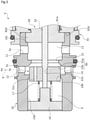
FIG. 1 is a sectional view showing a structure of a capacity control valve according to a first embodiment of the present invention. -
FIG. 2 is a sectional view showing a closed state of a CS valve in a non-energized state of the capacity control valve according to the first embodiment of the present invention. -
FIG. 3 is a sectional view showing an open state of the CS valve in an energized state of the capacity control valve according to the first embodiment of the present invention. -
FIG. 4 is a sectional view showing a structure of a capacity control valve according to a second embodiment of the present invention. -
FIG. 5 is a sectional view showing a closed state of a CS valve in a non-energized state of the capacity control valve according to the second embodiment of the present invention. -
FIG. 6 is a sectional view showing an open state of the CS valve in an energized state of the capacity control valve according to the second embodiment of the present invention. -
FIG. 7 is a sectional view showing a structure of a capacity control valve according to a third embodiment of the present invention. -
FIG. 8 is a sectional view showing a closed state of a CS valve in a non-energized state of the capacity control valve according to the third embodiment of the present invention. -
FIG. 9 is a sectional view showing an open state of the CS valve in an energized state of the capacity control valve according to the third embodiment of the present invention. - Modes for carrying out a capacity control valve according to the present invention will be described below based on embodiments.
- A capacity control valve according to a first embodiment of the present invention will be described with reference to
FIGS. 1 to 3 . Hereinafter, description will be given with the left and right sides seen from the front side ofFIG. 1 being the left and right sides of the capacity control valve. - A capacity control valve V according to the first embodiment of the present invention is assembled into a variable displacement compressor (not shown) used for an air conditioning system of an automobile, etc. By variably controlling pressure of a working fluid (hereinafter, simply referred to as the "fluid") serving as a coolant, a discharge amount of the variable displacement compressor is controlled and the air conditioning system is adjusted to have a desired cooling ability.
- First, the variable displacement compressor will be described. The variable displacement compressor has a casing including a discharge chamber, a suction chamber, a control chamber, and plural cylinders. A communication passage providing direct communication between the discharge chamber and the control chamber is provided in the variable displacement compressor and a
fixed orifice 9 for adjusting and balancing pressure between the discharge chamber and the control chamber is provided in this communication passage (seeFIGS. 1 to 3 ). - The variable displacement compressor also includes a rotating shaft to be driven and rotated by an engine (not shown) installed outside the casing, a swash plate coupled to the rotating shaft in an eccentric state by a hinge mechanism in the control chamber, and plural pistons coupled to the swash plate and fitted reciprocatably in the respective cylinders. With using the capacity control valve V to be driven to open and close by electromagnetic force, a tilt angle of the swash plate is continuously changed by appropriately controlling pressure in the control chamber while utilizing suction pressure Ps of the suction chamber that suctions the fluid, discharge pressure Pd of the discharge chamber that discharges the fluid pressurized by the pistons, and control pressure Pc of the control chamber that houses the swash plate. Thereby, a stroke amount of the pistons is changed to control a discharge amount of the fluid.
- As shown in
FIG. 1 , the capacity control valve V assembled into the variable displacement compressor adjusts an electric current energized in acoil 86 forming asolenoid 80 and performs open/close control of aCS valve 50 in the capacity control valve V so that the fluid flowing out to the suction chamber from the control chamber is controlled and the control pressure Pc in the control chamber is variably controlled. A discharge fluid of the discharge pressure Pd of the discharge chamber is always supplied to the control chamber via thefixed orifice 9, and the control pressure Pc in the control chamber can be increased by closing theCS valve 50 in the capacity control valve V. - In the present embodiment, the
CS valve 50 includes aCS valve element 51 which is a valve element and aCS valve seat 10a which is formed on an inner peripheral surface of thevalve housing 10 and an axiallyright end 51a of theCS valve element 51 moves to be in contact with and separated from theCS valve seat 10a so that theCS valve 50 is opened and closed. - Next, a structure of the capacity control valve V will be described. As shown in
FIG. 1 , the capacity control valve V mainly includes avalve housing 10 which is formed of a metal material or a resin material, aCS valve element 51 of which an axially left end portion is disposed inside thevalve housing 10, and asolenoid 80 which is connected to thevalve housing 10 and applies drive force to theCS valve element 51. - As shown in
FIGS. 1 to 3 , theCS valve element 51 is a cylindrical body which has a throughhole 51b formed at the center portion to penetrate in the axial direction and an axially left end portion of arod 52 disposed to penetrate thecoil 86 of thesolenoid 80 is press-inserted and fixed to the throughhole 51b. Further, in theCS valve element 51, acommunication passage 51c which penetrates in the axial direction is formed at a position shifted from thethrough hole 51b in the radial direction. In addition, thecommunication passage 51c may be provided at a plurality of positions and this is preferable in that the suction fluid can easily flow in and out. - As shown in
FIGS. 1 and2 , thevalve housing 10 is provided with aPs port 11 which is a suction port communicating with the suction chamber of the variable displacement compressor and aPc port 12 which is a control port communicating with the control chamber of the variable displacement compressor. ThePs port 11 is formed on the axially right side in relation to thePc port 12, specifically, theCS valve seat 10a. - A suction
fluid supply chamber 13 to which the suction fluid is supplied from thePs port 11, a controlfluid supply chamber 14 to which the control fluid is supplied from thePc port 12, avalve opening portion 15 which is disposed between the suctionfluid supply chamber 13 and the controlfluid supply chamber 14 and in which theCS valve seat 10a is formed at the axially left edge portion, arecessed portion 10d which opens to the axially left side and is disposed on the axially left side in relation to the controlfluid supply chamber 14, and aguide hole 10b which is provided in the bottom of therecessed portion 10d, that is, the axially right end of therecessed portion 10d and is slidable on the outer peripheral surface of theCS valve element 51 in a substantially sealed state are provided inside thevalve housing 10. - An opening portion of the axially left end of the recessed
portion 10d is closed by thelid member 16 and a space S defined by therecessed portion 10d, thelid member 16, and theCS valve element 51 is formed inside thevalve housing 10. In addition, the inner peripheral surface of theguide hole 10b and the outer peripheral surface of theCS valve element 51 are slightly separated from each other in the radial direction so that a minute gap is formed therebetween, theCS valve element 51 is smoothly relatively movable in the axial direction with respect to thevalve housing 10, and the gap functions as a clearance seal that substantially seals the space S and the controlfluid supply chamber 14. - The suction
fluid supply chamber 13 and the space S communicate with each other by thecommunication passage 51c formed in theCS valve element 51. That is, the suction fluid supplied into the suctionfluid supply chamber 13 flows into the space S through thecommunication passage 51c. Further, aspring 17 which is bias means biasing theCS valve element 51 rightward in the axial direction is disposed in the space S. - In the
valve housing 10, a recessedportion 10c of which an inner radial side of an axially right end is recessed leftward in the axial direction is formed and aflange portion 82d of thecenter post 82 is inserted and fitted from the axially right side so as to be integrally connected and fixed in a substantially sealed state. In addition, an opening end on the side of thesolenoid 80 of the suctionfluid supply chamber 13 is formed on the inner radial side of the bottom surface of the recessedportion 10c of thevalve housing 10. - As shown in
FIG. 1 , thesolenoid 80 mainly includes acasing 81 which has anopening portion 81a opening to the axially left side, a substantiallycylindrical center post 82 which is inserted into theopening portion 81a of thecasing 81 from the axially left side and is fixed to the inner radial side of thecasing 81, therod 52 which is inserted through thecenter post 82, is axially and reciprocatably movable, and is disposed so that an axially left end portion is located on the axially left side in relation to theCS valve seat 10a, theCS valve element 51 which is press-inserted and fixed to the axially left end portion of therod 52, amovable iron core 84 into which the axially right end portion of therod 52 is inserted and fixed, and theexcitation coil 86 which is wound on the outside of thecenter post 82 through a bobbin. - The
casing 81 is provided with a recessedportion 81b which is formed by recessing the inner radial side of the axially left end rightward in the axial direction and the axially right end portion of thevalve housing 10 is inserted and fixed to the recessedportion 81b in a substantially sealed state. - The
center post 82 is formed from a rigid body that is a magnetic material such as iron or silicon steel and includes acylindrical portion 82b that extends in the axial direction and is provided with aninsertion hole 82c into which therod 52 is inserted and anannular flange portion 82d that extends radially outward from the outer peripheral surface of the axially left end portion of thecylindrical portion 82b. - Further, the
center post 82 is inserted and fixed to the recessedportion 10c of thevalve housing 10 inserted and fixed to the recessedportion 81b of thecasing 81 in a substantially sealed state while the axially right end surface of theflange portion 82d comes into contact with the bottom surface of the recessedportion 81b of thecasing 81 from the axially left side. That is, thecenter post 82 is fixed by sandwiching theflange portion 82d between the bottom surface of the recessedportion 81b of thecasing 81 and the bottom surface of the recessedportion 10c of thevalve housing 10 from both sides in the axial direction. - Next, actions of the capacity control valve V, mainly actions of opening and closing the
CS valve 50 will be described. - First, a non-energized state of the capacity control valve V will be described. As shown in
FIGS. 1 and2 , in a non-energized state of the capacity control valve V, theCS valve element 51 is pressed to the axially right side by the bias force of thespring 17 so that the axiallyright end 51a of theCS valve element 51 is seated on theCS valve seat 10a to close theCS valve 50. Specifically, the edge portion of the axiallyright end 51a of theCS valve element 51 is seated on theCS valve seat 10a formed in a tapered shape to be enlarged toward the axially left side. - At this time, to the
CS valve element 51, the bias force Fsp of thespring 17 and force FP1 by pressure of the fluid to an axially left end surface of theCS valve element 51 are applied to the axially right side and force FP2 by pressure of the fluid to the axially right end surface of theCS valve element 51 is applied to the axially left side. That is, given that the right side is the positive side, force Frod = Fsp + FP1 - FP2 is applied to theCS valve element 51. - Specifically, a fluid inside the space S is applied to the axially left end surface of the
CS valve element 51 and a fluid inside the suctionfluid supply chamber 13 is applied to the axially right end surface of theCS valve element 51. Since the suctionfluid supply chamber 13 and the space S communicate with each other by thecommunication passage 51c formed in theCS valve element 51, the suction fluid supplied from thePs port 11 flows to the space S and the suctionfluid supply chamber 13. Further, the axially left end surface of theCS valve element 51 is formed to have the same diameter as that of the axially right end surface. In other words, an effective pressure receiving area A of theCS valve element 51 where the fluid of the space S is applied is the same as an effective pressure receiving area B of theCS valve element 51 where the fluid inside the suctionfluid supply chamber 13 is applied (i.e., A = B). - In this way, since the fluid flowing into the space S and the suction
fluid supply chamber 13 is the same as the suction fluid supplied from thePc port 12 and the effective pressure receiving areas A and B of theCS valve element 51 are the same, the force FP1 by the pressure of the fluid to the axially left end surface of theCS valve element 51 and the force FP2 to the axially right end surface of theCS valve element 51 are the same (i.e., FP1 = FP2) and the force FP1 by the pressure of the fluid and the force FP2 by the pressure of the fluid are canceled. That is, given that the right side is the positive side, the force Frod = Fsp is substantially applied to theCS valve element 51. - Next, an energized state of the capacity control valve V will be described. As shown in
FIGS. 1 and3 , in the capacity control valve V, in an energized state, that is, at the time of normal control or so-called duty control, when electromagnetic force Fsol generated by applying an electric current to thesolenoid 80 exceeds the force Frod (i.e., Fsol > Frod), themovable iron core 84 is pulled toward the axially left side, that is, toward thecenter post 82 and both theCS valve element 51 and therod 52 fixed to themovable iron core 84 are moved toward the axially left side so that the axiallyright end 51a of theCS valve element 51 is separated from theCS valve seat 10a of thevalve housing 10 to open theCS valve 50. Further, themovable iron core 84 contacts the axially right side of thecenter post 82 at the time of driving thesolenoid 80, the further separation of theCS valve element 51 from theCS valve seat 10a is regulated. In addition, the axially left end of therod 52 may contact the shaft portion protruding rightward from thelid member 16 to regulate the movement of theCS valve element 51. - At this time, to the
CS valve element 51, the electromagnetic force Fsol is applied on the axially left side, and the force Frod is applied on the axially right side. That is, given that the right side is the positive side, force Frod - Fsol is applied to theCS valve element 51. - In this way, the capacity control valve V performs Pc-Ps control by opening and closing the
CS valve 50 so that the control fluid of the control pressure Pc supplied from thePc port 12 is supplied to the suction chamber through thePs port 11 to decrease the control pressure Pc of the control chamber. In other words, the discharge fluid of the discharge pressure Pd having a high pressure is not directly controlled. Therefore, it is possible to finely change the control pressure Pc in accordance with the valve opening degree of theCS valve 50 adjusted by the balance of the electromagnetic force of thesolenoid 80 and the bias force of thespring 17. - As described above, since the space S is formed on the driving direction side of the
solenoid 80 in relation to theCS valve element 51, that is, the operation direction side of theCS valve element 51 and the suction fluid having a pressure lower than that of the control fluid flows into this space S, it is possible to decrease a drag force applied to theCS valve element 51 when theCS valve 50 is switched from the closed state to the open state and to immediately operate theCS valve element 51. In particular, since the capacity control valve V is formed in a normally closed type in which theCS valve element 51 is biased by thespring 17 in the valve closing direction of theCS valve 50, it is possible to promptly decrease the control pressure Pc by immediately operating theCS valve element 51 to open theCS valve 50. - Further, since the
spring 17 is disposed in the space S into which the suction fluid flows, it is not necessary to ensure a space for disposing thespring 17 on the side of thesolenoid 80 and it is possible to configure the capacity control valve V in a compact size. Further, since thespring 17 is disposed on the side opposite to thesolenoid 80 in theCS valve element 51, it is possible to stably operate theCS valve element 51. - Further, the
communication passage 51c is formed for communication between the space S and thePs port 11 and the control fluid can flow from thePs port 11 formed in thevalve housing 10 to the space S through thecommunication passage 51c. Accordingly, it is not necessary to form, for example, a suction port in thevalve housing 10 or thelid member 16 separately from thePs port 11 and it is possible to simplify the structure of the capacity control valve V. - Further, since the
communication passage 51c is formed to penetrate theCS valve element 51 in the axial direction, it is easy to process the communication passage for communication between the space S and thePs port 11 compared to a case in which the communication passage is formed in thevalve housing 10. - Further, since the space S and the
Pc port 12 are partitioned by theCS valve element 51, thevalve housing 10 is provided with theguide hole 10b which guides the movement of theCS valve element 51, and the space S and thePc port 12 are partitioned in a substantially sealed state by the clearance seal formed between the inner peripheral surface of theguide hole 10b and the outer peripheral surface of theCS valve element 51, it is possible to suppress the control fluid from flowing into the space S in the closed state of theCS valve 50. In other words, since it is easy to hold the suction fluid inside the space S, it is possible to reliably decrease a drag force applied to theCS valve element 51 when theCS valve 50 is switched from the closed state to the open state. Further, since the space S and thePc port 12 are partitioned in a substantially sealed state by the clearance seal formed between the inner peripheral surface of theguide hole 10b and the outer peripheral surface of theCS valve element 51, it is not necessary to separately provide a member for partitioning the space S and thePc port 12 and it is possible to decrease the number of parts and to simplify the structure of the capacity control valve V. - Further, since the
valve housing 10 is provided with theguide hole 10b through which theCS valve element 51 is inserted, it is possible to increase the accuracy of the operation of theCS valve element 51 by guiding theCS valve element 51 to theguide hole 10b. Further, since theCS valve seat 10a and theguide hole 10b are integrally formed with each other in thevalve housing 10, it is possible to provide a compact capacity control valve V with a small number of parts. - Additionally, in the first embodiment, a case has been described in which the effective pressure receiving area A of the
CS valve element 51 where the fluid of the space S is applied is the same as the effective pressure receiving area B of theCS valve element 51 where the fluid inside the suctionfluid supply chamber 13 is applied. However, the effective pressure receiving area A may be slightly larger than the effective pressure receiving area B (i.e., A > B) so that theCS valve 50 is reliably maintained in the closed state and the effective pressure receiving area A may be slightly smaller than the effective pressure receiving area B (i.e., A < B) so that theCS valve 50 is easily maintained in the open state. - A capacity control valve according to a second embodiment of the present invention will be described with reference to
FIGS. 4 to 6 . Duplicated description for the same configurations as the first embodiment is omitted. - As shown in
FIGS. 4 and5 , in the second embodiment, theCS valve element 151 of theCS valve 150 is formed in a tapered shape so that an axiallyright end 151a is tapered to the axially right side and is seated on theCS valve seat 10a in a wide surface in the closed state of theCS valve 150. Further, acommunication passage 151c is formed in theCS valve element 151 to penetrate in the axial direction. Further, the axially right end surface of theCS valve element 151 is slightly smaller than the axially left end surface of theCS valve element 151. - The control
fluid supply chamber 14 of the second embodiment communicates with the recessedportion 10d and abellows 18 which is bias means for biasing theCS valve element 151 to the axially right side, that is, in the valve closing direction of theCS valve 150 is disposed in the controlfluid supply chamber 14 instead of thespring 17. In thebellows 18, the axially left end is fixed to alid member 161 closing the recessedportion 10d in a substantially sealed state and the axially right end is fixed to the axially left end surface of theCS valve element 151 in a substantially sealed state so that a space S1 is formed therein. Further, the suctionfluid supply chamber 13 communicates with the space S1 through thecommunication passage 151c and the suction fluid inside the suctionfluid supply chamber 13 flows into the space S1. That is, thebellows 18 partitions the space S1 and the controlfluid supply chamber 14 in a sealed state when theCS valve 150 is in the closed state. In addition, a spring for axial biasing may be assembled to thebellows 18. That is, an effective pressure receiving area A' of thebellows 18 is formed to be slightly larger than an effective pressure receiving area B' on the axially right side of the CS valve element 151 (i.e., A' > B'). - Next, actions of the capacity control valve V1, mainly actions of opening and closing the
CS valve 150 will be described. - First, a non-energized state of the capacity control valve V1 will be described. As shown in
FIGS. 4 and5 , in a non-energized state of the capacity control valve V, theCS valve element 151 is pressed to the axially right side by the bias force of thebellows 18 so that the axiallyright end 151a of theCS valve element 151 is seated on theCS valve seat 10a to close theCS valve 150. - At this time, to the
CS valve element 151, the bias force Fbel of thebellows 18 and force FP1 by pressure of the fluid to the axially left end surface of theCS valve element 151 are applied to the axially right side and force FP2 by pressure of the fluid to the axially right surface of theCS valve element 151 is applied to the axially left side. That is, given that the right side is the positive side, force Frod = Fsp + FP1 - FP2 is applied to theCS valve element 151. - Specifically, since the effective pressure receiving area A' on the axially left side of the
CS valve element 151 is slightly larger than the effective pressure receiving area B' on the axially right side, the force FP1 by the pressure of the fluid to the axially left end surface of theCS valve element 151 is slightly larger than the force FP2 by the pressure of the fluid to the axially right surface of the CS valve element 151 (i.e., FP1 > FP2). Accordingly, it is easy to maintain the closed state of theCS valve 150 even when a slight pressure difference is immediately generated between the pressure inside the space S1 and the pressure inside the suctionfluid supply chamber 13. - Next, an energized state of the capacity control valve V1 will be described. As shown in
FIGS. 4 and6 , in the capacity control valve V1, in an energized state, that is, at the time of normal control or so-called duty control, when electromagnetic force Fsol generated by applying an electric current to thesolenoid 80 exceeds the force Frod (i.e., Fsol > Frod), themovable iron core 84 is pulled toward the axially left side, that is, toward thecenter post 82 and both theCS valve element 151 and therod 52 fixed to themovable iron core 84 are moved toward the axially left side so that the axiallyright end 151a of theCS valve element 151 is separated from theCS valve seat 10a of thevalve housing 10 to open theCS valve 150. - In this way, since the suction fluid flows into the space S1 formed on the operation direction side of the
CS valve element 151, it is possible to immediately operate theCS valve element 151 by decreasing a drag force applied to theCS valve element 151 when theCS valve 150 is switched from the closed state to the open state. - Further, since the space S1 and the
Pc port 12 are partitioned in a substantially sealed state by thebellows 18, it is possible to prevent the control fluid from flowing into the space S1 in the closed state of theCS valve 150. In other words, since it is possible to hold the suction fluid inside the space S1 in the closed state of theCS valve 150, it is possible to reliably decrease a drag force applied to theCS valve element 151 when theCS valve 150 is switched from the closed state to the open state. Further, since thebellows 18 partitioning the space S1 and thePc port 12 also serves as bias means, the capacity control valve V1 can have a simple configuration. - Additionally, in the second embodiment, a case has been described in which the
bellows 18 has a function of partitioning the space S1 and thePc port 12 and a function of the bias means, but if the bias means biasing theCS valve element 151 in the valve closing direction is separately provided, thebellows 18 may not have the bias force. - A capacity control valve according to a third embodiment of the present invention will be described with reference to
FIGS. 7 to 9 . Duplicated description for the same configurations as the first embodiment is omitted. - As shown in
FIGS. 7 and8 , aCS valve element 251 includes alarge diameter portion 251A which is movable to be in contact with and separated from theCS valve seat 210a of thevalve housing 210 and a cylindricalsmall diameter portion 251B which protrudes toward the axially right side from the center of thelarge diameter portion 251A and an axially left end of arod 252 is press-inserted and fixed to thesmall diameter portion 251B. - Further, in the
valve housing 210 of the third embodiment, thePs port 11 is formed on the axially left side in relation to theCS valve seat 210a and thePc port 12 is formed on the axially right side in relation to theCS valve seat 210a. Further, a space S2 which is partitioned by a recessedportion 210d, alid member 216, and theCS valve element 251 is formed on the axially left side, that is, the operation direction side of theCS valve element 251 in relation to theCS valve seat 210a of thevalve housing 210 and the space S2 functions as the suctionfluid supply chamber 13. Further, in thevalve housing 210, theCS valve seat 210a is formed between the controlfluid supply chamber 14 and the suctionfluid supply chamber 13. Further, aspring 217 which is bias means for biasing theCS valve element 251 toward the axially right side, that is, toward theCS valve seat 210a is disposed in the space S2. - Next, actions of the capacity control valve V2, mainly actions of opening and closing the
CS valve 250 will be described. - First, a non-energized state of the capacity control valve V2 will be described. As shown in
FIGS. 7 and8 , in a non-energized state of the capacity control valve V, theCS valve element 251 is pressed to the axially right side by the bias force of thespring 217 so that an axiallyright end 251a of thelarge diameter portion 251A of theCS valve element 251 is seated on theCS valve seat 210a to close theCS valve 250. Specifically, the axiallyright end 251a of the taperedCS valve element 251 is seated on the edge portion of theCS valve seat 210a. - At this time, to the
CS valve element 251, the bias force Fsp of thespring 217 and force FP1 by pressure of the suction fluid to an axially left end surface of theCS valve element 251 are applied to the axially right side and force FP2 by pressure of the control fluid to the axially right surface of theCS valve element 251 is applied to the axially left side. That is, given that the right side is the positive side, force Frod = Fsp + FP1 - FP2 is applied to theCS valve element 251. - Next, an energized state of the capacity control valve V will be described. As shown in
FIGS. 7 and9 , in the capacity control valve V2, in an energized state, that is, at the time of normal control or so-called duty control, when electromagnetic force Fsol generated by applying an electric current to thesolenoid 80 exceeds the force Frod (i.e., Fsol > Frod), themovable iron core 84 is pulled toward the axially left side, that is, toward thecenter post 82 and both theCS valve element 251 and therod 252 fixed to themovable iron core 84 are moved toward the axially left side so that the axiallyright end 251a of theCS valve element 251 is separated from theCS valve seat 210a of thevalve housing 210 to open theCS valve 250. - In this way, since the suction fluid flows into the space S2 formed on the operation direction side of the
CS valve element 251, it is possible to immediately operate theCS valve element 251 by decreasing a drag force applied to theCS valve element 251 when theCS valve 250 is switched from the closed state to the open state. Further, since the control fluid is applied to the axially right surface of theCS valve element 251, it is easy to immediately operate theCS valve element 251 to the axially left side by a pressure difference between the suction fluid and the control fluid applied to the axially left and right surfaces of theCS valve element 251. - The embodiments of the present invention are described above with the drawings. However, specific configurations are not limited to these embodiments but the present invention includes changes and additions within the range not departing from the scope of the present invention.
- For example, in the above-described embodiments, a case has been described in which the CS valve element is formed as a member separated from the rod disposed to penetrate the
coil 86 of thesolenoid 80, but the present invention is not limited to this. The CS valve element and the rod may be integrally formed with each other. - The first embodiment describes that the CS valve seat and the guide hole are integrally formed on the inner peripheral surface of the valve housing. However, the present invention is not limited to this but a valve housing having a CS valve seat and a valve housing having a guide hole may be separately provided.
- A guide portion is not limited to be formed in the valve housing but may be formed in part of the
insertion hole 82c of thecenter post 82, for example. - In the above-described embodiments, a case has been described in which the bias means is disposed inside the space, but the bias means may be disposed in a place other than the space such as the solenoid side.
- In the first and second embodiments, a case has been described in which the Ps port communicates through the communication passage formed in the CS valve element, but the present invention is not limited to this. The communication passage may be formed in the valve housing. Further, the configuration of the communication passage may be omitted and another Ps port may be formed in the lid member or the valve housing forming the space to communicate with the suction chamber of the variable displacement compressor.
-
- 9
- Fixed orifice
- 10
- Valve housing
- 10a
- CS valve seat
- 10b
- Guide hole
- 11
- Ps port
- 12
- Pc port
- 13
- Suction fluid supply chamber
- 14
- Control fluid supply chamber
- 17
- Spring (biassing member)
- 18
- Bellows (biassing member)
- 50
- CS valve
- 51
- CS valve element
- 51c
- Communication passage
- 80
- Solenoid
- 82
- Center post
- 84
- Movable iron core
- 86
- Coil
- 150
- CS valve
- 151
- CS valve element
- 151c
- Communication passage
- 210
- Valve housing
- 210a
- CS valve seat
- 217
- Spring (biassing member)
- 250
- CS valve
- 251
- CS valve element
- A, A', B, B'
- Effective pressure receiving area
- Pc
- Control pressure
- Pd
- Discharge pressure
- Ps
- Suction pressure
- S, S1, S2
- Space
- V, V1, V2
- Capacity control valve
Claims (7)
- A capacity control valve comprising:a valve housing that is provided with a suction port through which a suction fluid of a suction pressure passes and a control port through which a control fluid of a control pressure passes;a CS valve that includes a CS valve element which is axially driven by a solenoid and a CS valve seat which is provided between the suction port and the control port and is brought into contact with and separated from the CS valve element; anda biasing member configured to bias the CS valve element in a valve closing direction of the CS valve,wherein a space is formed inside the valve housing in opposition to the solenoid through the CS valve element and the suction fluid flows into the space.
- The capacity control valve according to claim 1,
wherein the biassing member is disposed in the space. - The capacity control valve according to claim 1 or 2,
wherein a communication passage for a communication between the space and the suction port is provided. - The capacity control valve according to claim 3,
wherein the communication passage is formed in the CS valve element. - The capacity control valve according to any one of claims 1 to 4,
wherein the space and the control port are partitioned. - The capacity control valve according to claim 5,
wherein the space and the control port are partitioned by a bellows. - The capacity control valve according to claim 5,
wherein the space and the control port are partitioned by the CS valve element and the valve housing is provided with a guide hole having an inner periphery which slides on an outer periphery of the CS valve element to guide the CS valve element.
Applications Claiming Priority (2)
| Application Number | Priority Date | Filing Date | Title |
|---|---|---|---|
| JP2019082964 | 2019-04-24 | ||
| PCT/JP2020/017168 WO2020218284A1 (en) | 2019-04-24 | 2020-04-21 | Capacity control valve |
Publications (3)
| Publication Number | Publication Date |
|---|---|
| EP3961033A1 true EP3961033A1 (en) | 2022-03-02 |
| EP3961033A4 EP3961033A4 (en) | 2022-11-16 |
| EP3961033B1 EP3961033B1 (en) | 2025-03-12 |
Family
ID=72941924
Family Applications (1)
| Application Number | Title | Priority Date | Filing Date |
|---|---|---|---|
| EP20795975.0A Active EP3961033B1 (en) | 2019-04-24 | 2020-04-21 | Capacity control valve |
Country Status (5)
| Country | Link |
|---|---|
| US (1) | US12031531B2 (en) |
| EP (1) | EP3961033B1 (en) |
| JP (1) | JP7467427B2 (en) |
| CN (1) | CN113692491B (en) |
| WO (1) | WO2020218284A1 (en) |
Families Citing this family (6)
| Publication number | Priority date | Publication date | Assignee | Title |
|---|---|---|---|---|
| JP7673070B2 (en) | 2020-08-04 | 2025-05-08 | イーグル工業株式会社 | valve |
| KR102879499B1 (en) | 2020-09-28 | 2025-10-31 | 이구루코교 가부시기가이샤 | valve |
| EP4224032B1 (en) | 2020-10-01 | 2025-12-10 | Eagle Industry Co., Ltd. | Valve |
| EP4265949B1 (en) | 2020-12-17 | 2025-11-19 | Eagle Industry Co., Ltd. | Valve |
| JP7787104B2 (en) * | 2021-01-14 | 2025-12-16 | イーグル工業株式会社 | valve |
| US12510168B2 (en) | 2021-03-29 | 2025-12-30 | Eagle Industry Co., Ltd. | Valve |
Family Cites Families (94)
| Publication number | Priority date | Publication date | Assignee | Title |
|---|---|---|---|---|
| GB787961A (en) | 1954-07-14 | 1957-12-18 | William Hector Mashinter | Metering pump |
| US3765644A (en) | 1972-01-19 | 1973-10-16 | Control Concepts | Controlled air gap in a solenoid operated valve |
| JPS581598B2 (en) | 1978-05-15 | 1983-01-12 | 富士通株式会社 | Display image correction method |
| ES480613A1 (en) | 1978-06-28 | 1979-11-16 | Sibe | Solenoid valves, particularly for carburetors |
| JPS5983539U (en) | 1982-11-30 | 1984-06-06 | カシオ計算機株式会社 | ink cartridge |
| JPS6316177A (en) | 1986-07-08 | 1988-01-23 | Sanden Corp | Variable displacement type compressor |
| US5022629A (en) | 1988-01-04 | 1991-06-11 | Interface, Inc. | Valve construction |
| DE3934771C1 (en) | 1989-10-18 | 1991-03-28 | Lucas Industries P.L.C., Birmingham, West Midlands, Gb | |
| US5199855A (en) * | 1990-09-27 | 1993-04-06 | Zexel Corporation | Variable capacity compressor having a capacity control system using an electromagnetic valve |
| DE4103365A1 (en) | 1991-02-05 | 1992-08-13 | Teves Metallwaren Alfred | PRESSURE CONTROL VALVE |
| JPH04342883A (en) | 1991-05-17 | 1992-11-30 | Sanden Corp | Variable delivery swash plate type compressor |
| DE4137123A1 (en) | 1991-11-12 | 1993-05-13 | Teves Gmbh Alfred | PRESSURE CONTROL VALVE |
| JP3242496B2 (en) | 1993-07-06 | 2001-12-25 | 株式会社豊田自動織機 | External switching type displacement control valve for variable displacement compressor |
| JPH10318414A (en) | 1997-05-20 | 1998-12-04 | Toyota Autom Loom Works Ltd | Solenoid control valve |
| JPH11280658A (en) | 1998-03-25 | 1999-10-15 | Sanden Corp | Capacity control valve of variable capacity compressor |
| JP4149558B2 (en) | 1998-03-27 | 2008-09-10 | サンデン株式会社 | Volume control valve for variable capacity compressor |
| JP3783434B2 (en) | 1998-04-13 | 2006-06-07 | 株式会社豊田自動織機 | Variable capacity swash plate compressor and air conditioning cooling circuit |
| JPH11336660A (en) | 1998-05-27 | 1999-12-07 | Toyota Autom Loom Works Ltd | Variable displacement compressor and assembling method therefor |
| JP2000064957A (en) | 1998-08-17 | 2000-03-03 | Toyota Autom Loom Works Ltd | Variable displacement swash prate compressor and extraction side control valve |
| JP3984724B2 (en) | 1998-09-10 | 2007-10-03 | 株式会社豊田自動織機 | Control valve for variable capacity swash plate compressor and swash plate compressor |
| JP3435077B2 (en) | 1998-09-16 | 2003-08-11 | 株式会社鷺宮製作所 | Bellows pressure operated valve |
| JP2000161234A (en) | 1998-11-27 | 2000-06-13 | Toyota Autom Loom Works Ltd | Variable displacement type compressor, and its displacement control valve |
| JP3581598B2 (en) | 1999-04-21 | 2004-10-27 | 株式会社テージーケー | Capacity control device for variable capacity compressor |
| JP3576866B2 (en) | 1999-05-10 | 2004-10-13 | 株式会社テージーケー | Refrigeration cycle with bypass line for vehicles |
| JP4392631B2 (en) * | 1999-06-24 | 2010-01-06 | 株式会社ヴァレオサーマルシステムズ | Variable capacity controller for refrigeration cycle |
| JP3991556B2 (en) | 1999-10-04 | 2007-10-17 | 株式会社豊田自動織機 | Control valve for variable capacity compressor |
| JP3963619B2 (en) | 1999-11-05 | 2007-08-22 | 株式会社テージーケー | Compression capacity controller for refrigeration cycle |
| JP2001153043A (en) | 1999-12-01 | 2001-06-05 | Sanden Corp | Variable displacement type swash plate compressor |
| JP2001165055A (en) | 1999-12-09 | 2001-06-19 | Toyota Autom Loom Works Ltd | Control valve and displacement variable compressor |
| JP2002070732A (en) | 2000-09-01 | 2002-03-08 | Zexel Valeo Climate Control Corp | Variable displacement controller for refrigeration cycle |
| JP2002089442A (en) | 2000-09-08 | 2002-03-27 | Toyota Industries Corp | Control valve for variable displacement compressor |
| JP2002201913A (en) | 2001-01-09 | 2002-07-19 | Mitsubishi Heavy Ind Ltd | Split wall of gas turbine and shroud |
| JP2002221153A (en) | 2001-01-23 | 2002-08-09 | Toyota Industries Corp | Control valve for variable displacement type compressor |
| JP3943871B2 (en) | 2001-07-25 | 2007-07-11 | 株式会社テージーケー | Variable capacity compressor and capacity control valve for variable capacity compressor |
| DE10297516B4 (en) | 2001-12-11 | 2008-08-28 | Kayaba Industry Co., Ltd. | Electromagnetic proportional flow control valve |
| JP4246975B2 (en) | 2002-02-04 | 2009-04-02 | イーグル工業株式会社 | Capacity control valve |
| KR100466951B1 (en) | 2002-04-01 | 2005-01-24 | 현대모비스 주식회사 | Anti-Lock Brake System Solenoid Valve |
| GB0214467D0 (en) | 2002-06-24 | 2002-08-07 | Delphi Tech Inc | Control valve for air conditioning compressor |
| JP4242624B2 (en) | 2002-09-26 | 2009-03-25 | イーグル工業株式会社 | Capacity control valve and control method thereof |
| JP2004162567A (en) | 2002-11-12 | 2004-06-10 | Fuji Koki Corp | Control valve for variable displacement compressor |
| JP2004162640A (en) | 2002-11-14 | 2004-06-10 | Toyota Industries Corp | Control valve for variable displacement compressor |
| JP2004162856A (en) | 2002-11-15 | 2004-06-10 | Hitachi Unisia Automotive Ltd | Solenoid valve structure |
| DE10321413B4 (en) | 2003-05-13 | 2014-06-26 | Robert Bosch Gmbh | Electromagnetically actuated valve |
| JP2005098197A (en) | 2003-09-04 | 2005-04-14 | Tgk Co Ltd | Capacity control valve for variable displacement compressor |
| JP2005291142A (en) | 2004-04-02 | 2005-10-20 | Zexel Valeo Climate Control Corp | Control device and pressure control valve for variable displacement compressor |
| JP2006097665A (en) | 2004-06-28 | 2006-04-13 | Toyota Industries Corp | Capacity control valve in variable displacement compressor |
| JP2006017087A (en) | 2004-07-05 | 2006-01-19 | Calsonic Kansei Corp | Electromagnetic control valve and variable displacement compressor equipped with the same |
| JP4431462B2 (en) | 2004-08-10 | 2010-03-17 | 株式会社鷺宮製作所 | Swash plate type variable capacity compressor and electromagnetic control valve |
| JP4626808B2 (en) | 2005-04-26 | 2011-02-09 | 株式会社豊田自動織機 | Capacity control valve for variable capacity clutchless compressor |
| JP2007092829A (en) | 2005-09-28 | 2007-04-12 | Toyota Motor Corp | Valve |
| JP2007177627A (en) | 2005-12-27 | 2007-07-12 | Sanden Corp | Discharge capacity control valve of variable displacement compressor |
| DE102006002638A1 (en) | 2006-01-19 | 2007-07-26 | Robert Bosch Gmbh | magnetic valve |
| CN2869383Y (en) | 2006-02-17 | 2007-02-14 | 苏州新智机电工业有限公司 | Automobile air-conditioning variable displacement compressor control valve |
| JP5128466B2 (en) * | 2006-03-29 | 2013-01-23 | イーグル工業株式会社 | Control valve for variable displacement compressor |
| FR2901340A1 (en) | 2006-05-17 | 2007-11-23 | Messier Bugatti Sa | HYDRAULIC DISPENSER ARRANGEMENT IN THE FORM OF A CARTRIDGE |
| JP2008157031A (en) | 2006-12-20 | 2008-07-10 | Toyota Industries Corp | Electromagnetic displacement control valve in clutchless variable displacement type compressor |
| EP2118542B1 (en) | 2007-01-10 | 2018-05-09 | Fritz Gyger Ag | Micro-valve |
| JP5222447B2 (en) | 2008-06-11 | 2013-06-26 | サンデン株式会社 | Variable capacity compressor |
| JP5251762B2 (en) | 2009-07-08 | 2013-07-31 | アイシン・エィ・ダブリュ株式会社 | Solenoid valve |
| JP5271216B2 (en) | 2009-09-17 | 2013-08-21 | 日立オートモティブシステムズ株式会社 | Normally open type solenoid valve |
| JP2011094554A (en) | 2009-10-30 | 2011-05-12 | Tgk Co Ltd | Variable displacement compressor |
| JP5878703B2 (en) | 2010-09-06 | 2016-03-08 | 株式会社不二工機 | Control valve for variable displacement compressor |
| JP5871281B2 (en) * | 2010-12-09 | 2016-03-01 | イーグル工業株式会社 | Capacity control valve |
| JP5443444B2 (en) | 2011-07-06 | 2014-03-19 | 株式会社鷺宮製作所 | Pressure sensitive control valve |
| DE102011055281B3 (en) | 2011-11-11 | 2013-02-21 | Pierburg Gmbh | Valve device for a hydraulic circuit and oil pump control arrangement |
| JP6281046B2 (en) | 2012-04-23 | 2018-02-21 | 株式会社テージーケー | Control valve for variable capacity compressor |
| US20150068628A1 (en) | 2012-05-24 | 2015-03-12 | Eagle Industry Co., Ltd. | Capacity control valve |
| JP2014055626A (en) | 2012-09-12 | 2014-03-27 | Saginomiya Seisakusho Inc | Pressure-sensitive control valve |
| JP6064131B2 (en) | 2012-10-17 | 2017-01-25 | 株式会社テージーケー | Control valve for variable capacity compressor |
| JP6085789B2 (en) | 2012-12-27 | 2017-03-01 | 株式会社テージーケー | Control valve for variable capacity compressor |
| EP2952741B1 (en) | 2013-01-31 | 2019-03-13 | Eagle Industry Co., Ltd. | Variable capacity compressor |
| WO2014148367A1 (en) | 2013-03-22 | 2014-09-25 | サンデン株式会社 | Control valve and variable capacity compressor provided with said control valve |
| JP5983539B2 (en) | 2013-06-13 | 2016-08-31 | 株式会社豊田自動織機 | Double-head piston type swash plate compressor |
| JP2015034510A (en) | 2013-08-08 | 2015-02-19 | 株式会社豊田自動織機 | Variable displacement swash plate compressor |
| JP2015121097A (en) | 2013-12-20 | 2015-07-02 | 株式会社ヴァレオジャパン | Pressure control valve and variable displacement compressor using the same |
| JP6127994B2 (en) | 2014-01-30 | 2017-05-17 | 株式会社豊田自動織機 | Variable capacity swash plate compressor |
| JP2016020682A (en) | 2014-06-19 | 2016-02-04 | 株式会社テージーケー | Control valve for variable capacity type compressor |
| DE102014116214B3 (en) | 2014-11-06 | 2016-02-04 | Eto Magnetic Gmbh | Proportional valve, air conditioning compressor arrangement and operating method |
| JP6505745B2 (en) | 2014-11-13 | 2019-04-24 | イーグル工業株式会社 | Solenoid valve device |
| JP2016125376A (en) | 2014-12-26 | 2016-07-11 | 株式会社テージーケー | Control valve for variable displacement compressor |
| JP2017031834A (en) | 2015-07-29 | 2017-02-09 | 株式会社豊田自動織機 | Capacity control valve |
| WO2017057160A1 (en) | 2015-09-29 | 2017-04-06 | 株式会社ヴァレオジャパン | Variable displacement compressor control valve |
| JP6395696B2 (en) | 2015-12-16 | 2018-09-26 | 株式会社不二工機 | Control valve for variable displacement compressor |
| JP6626789B2 (en) | 2016-06-28 | 2019-12-25 | 株式会社不二工機 | Control valve for variable displacement compressor |
| US10781804B2 (en) | 2016-08-29 | 2020-09-22 | Eagle Industry Co., Ltd. | Displacement control valve |
| JP6632503B2 (en) | 2016-09-30 | 2020-01-22 | 株式会社不二工機 | Control valve for variable displacement compressor |
| JP6924476B2 (en) | 2017-04-07 | 2021-08-25 | 株式会社テージーケー | Control valve for variable displacement compressor |
| JP6667114B2 (en) | 2017-09-21 | 2020-03-18 | 株式会社アドヴィックス | solenoid valve |
| US11320061B2 (en) | 2017-11-22 | 2022-05-03 | Eagle Industry Co., Ltd. | Solenoid valve |
| JP6991890B2 (en) | 2018-02-23 | 2022-01-13 | イーグル工業株式会社 | Spool valve |
| US20190331249A1 (en) | 2018-04-25 | 2019-10-31 | Sun Hydraulics, Llc | Proportional Normally-Open Valve with a Biasing Spring |
| WO2020013169A1 (en) | 2018-07-13 | 2020-01-16 | イーグル工業株式会社 | Capacity control valve |
| US11231111B2 (en) | 2019-05-14 | 2022-01-25 | Halliburton Energy Services, Inc. | Pump valve seat with supplemental retention |
| CN220046247U (en) | 2023-03-31 | 2023-11-21 | 日丸物产株式会社 | Mosquito-repellent phase-change cooling neck ring |
-
2020
- 2020-04-21 EP EP20795975.0A patent/EP3961033B1/en active Active
- 2020-04-21 WO PCT/JP2020/017168 patent/WO2020218284A1/en not_active Ceased
- 2020-04-21 JP JP2021516128A patent/JP7467427B2/en active Active
- 2020-04-21 US US17/603,291 patent/US12031531B2/en active Active
- 2020-04-21 CN CN202080028860.XA patent/CN113692491B/en active Active
Also Published As
| Publication number | Publication date |
|---|---|
| EP3961033A4 (en) | 2022-11-16 |
| CN113692491B (en) | 2023-07-04 |
| US12031531B2 (en) | 2024-07-09 |
| JPWO2020218284A1 (en) | 2020-10-29 |
| EP3961033B1 (en) | 2025-03-12 |
| WO2020218284A1 (en) | 2020-10-29 |
| US20220213878A1 (en) | 2022-07-07 |
| CN113692491A (en) | 2021-11-23 |
| JP7467427B2 (en) | 2024-04-15 |
Similar Documents
| Publication | Publication Date | Title |
|---|---|---|
| EP3961033B1 (en) | Capacity control valve | |
| EP3835578B1 (en) | Capacity control valve | |
| EP3822484A1 (en) | Capacity control valve | |
| EP3754190A1 (en) | Capacity control valve | |
| EP3951172B1 (en) | Capacity control valve | |
| EP4148274A1 (en) | Capacity control valve | |
| EP3892856A1 (en) | Displacement control valve | |
| EP3998401B1 (en) | Capacity control valve | |
| EP3822483A1 (en) | Capacity control valve | |
| EP3835577B1 (en) | Capacity control valve | |
| EP3892855B1 (en) | Capacity control valve | |
| US11473683B2 (en) | Capacity control valve | |
| EP3951173B1 (en) | Capacity control valve | |
| EP3951170B1 (en) | Capacity control valve | |
| EP3951171B1 (en) | Capacity control valve | |
| EP4234997A2 (en) | Capacity control valve | |
| EP3998403B1 (en) | Capacity control valve |
Legal Events
| Date | Code | Title | Description |
|---|---|---|---|
| STAA | Information on the status of an ep patent application or granted ep patent |
Free format text: STATUS: THE INTERNATIONAL PUBLICATION HAS BEEN MADE |
|
| PUAI | Public reference made under article 153(3) epc to a published international application that has entered the european phase |
Free format text: ORIGINAL CODE: 0009012 |
|
| STAA | Information on the status of an ep patent application or granted ep patent |
Free format text: STATUS: REQUEST FOR EXAMINATION WAS MADE |
|
| 17P | Request for examination filed |
Effective date: 20211025 |
|
| AK | Designated contracting states |
Kind code of ref document: A1 Designated state(s): AL AT BE BG CH CY CZ DE DK EE ES FI FR GB GR HR HU IE IS IT LI LT LU LV MC MK MT NL NO PL PT RO RS SE SI SK SM TR |
|
| DAV | Request for validation of the european patent (deleted) | ||
| DAX | Request for extension of the european patent (deleted) | ||
| A4 | Supplementary search report drawn up and despatched |
Effective date: 20221019 |
|
| RIC1 | Information provided on ipc code assigned before grant |
Ipc: F16K 39/02 20060101ALI20221013BHEP Ipc: F16K 31/06 20060101ALI20221013BHEP Ipc: F04B 49/12 20060101ALI20221013BHEP Ipc: F04B 27/18 20060101AFI20221013BHEP |
|
| STAA | Information on the status of an ep patent application or granted ep patent |
Free format text: STATUS: EXAMINATION IS IN PROGRESS |
|
| 17Q | First examination report despatched |
Effective date: 20240503 |
|
| GRAP | Despatch of communication of intention to grant a patent |
Free format text: ORIGINAL CODE: EPIDOSNIGR1 |
|
| STAA | Information on the status of an ep patent application or granted ep patent |
Free format text: STATUS: GRANT OF PATENT IS INTENDED |
|
| INTG | Intention to grant announced |
Effective date: 20241122 |
|
| GRAS | Grant fee paid |
Free format text: ORIGINAL CODE: EPIDOSNIGR3 |
|
| GRAA | (expected) grant |
Free format text: ORIGINAL CODE: 0009210 |
|
| STAA | Information on the status of an ep patent application or granted ep patent |
Free format text: STATUS: THE PATENT HAS BEEN GRANTED |
|
| AK | Designated contracting states |
Kind code of ref document: B1 Designated state(s): AL AT BE BG CH CY CZ DE DK EE ES FI FR GB GR HR HU IE IS IT LI LT LU LV MC MK MT NL NO PL PT RO RS SE SI SK SM TR |
|
| REG | Reference to a national code |
Ref country code: GB Ref legal event code: FG4D |
|
| REG | Reference to a national code |
Ref country code: CH Ref legal event code: EP |
|
| REG | Reference to a national code |
Ref country code: DE Ref legal event code: R096 Ref document number: 602020047646 Country of ref document: DE |
|
| REG | Reference to a national code |
Ref country code: IE Ref legal event code: FG4D |
|
| PG25 | Lapsed in a contracting state [announced via postgrant information from national office to epo] |
Ref country code: RS Free format text: LAPSE BECAUSE OF FAILURE TO SUBMIT A TRANSLATION OF THE DESCRIPTION OR TO PAY THE FEE WITHIN THE PRESCRIBED TIME-LIMIT Effective date: 20250612 |
|
| PG25 | Lapsed in a contracting state [announced via postgrant information from national office to epo] |
Ref country code: FI Free format text: LAPSE BECAUSE OF FAILURE TO SUBMIT A TRANSLATION OF THE DESCRIPTION OR TO PAY THE FEE WITHIN THE PRESCRIBED TIME-LIMIT Effective date: 20250312 |
|
| PGFP | Annual fee paid to national office [announced via postgrant information from national office to epo] |
Ref country code: DE Payment date: 20250417 Year of fee payment: 6 |
|
| PG25 | Lapsed in a contracting state [announced via postgrant information from national office to epo] |
Ref country code: ES Free format text: LAPSE BECAUSE OF FAILURE TO SUBMIT A TRANSLATION OF THE DESCRIPTION OR TO PAY THE FEE WITHIN THE PRESCRIBED TIME-LIMIT Effective date: 20250312 |
|
| REG | Reference to a national code |
Ref country code: LT Ref legal event code: MG9D |
|
| PG25 | Lapsed in a contracting state [announced via postgrant information from national office to epo] |
Ref country code: NO Free format text: LAPSE BECAUSE OF FAILURE TO SUBMIT A TRANSLATION OF THE DESCRIPTION OR TO PAY THE FEE WITHIN THE PRESCRIBED TIME-LIMIT Effective date: 20250612 |
|
| PG25 | Lapsed in a contracting state [announced via postgrant information from national office to epo] |
Ref country code: HR Free format text: LAPSE BECAUSE OF FAILURE TO SUBMIT A TRANSLATION OF THE DESCRIPTION OR TO PAY THE FEE WITHIN THE PRESCRIBED TIME-LIMIT Effective date: 20250312 |
|
| REG | Reference to a national code |
Ref country code: NL Ref legal event code: MP Effective date: 20250312 |
|
| PG25 | Lapsed in a contracting state [announced via postgrant information from national office to epo] |
Ref country code: LV Free format text: LAPSE BECAUSE OF FAILURE TO SUBMIT A TRANSLATION OF THE DESCRIPTION OR TO PAY THE FEE WITHIN THE PRESCRIBED TIME-LIMIT Effective date: 20250312 |
|
| PG25 | Lapsed in a contracting state [announced via postgrant information from national office to epo] |
Ref country code: GR Free format text: LAPSE BECAUSE OF FAILURE TO SUBMIT A TRANSLATION OF THE DESCRIPTION OR TO PAY THE FEE WITHIN THE PRESCRIBED TIME-LIMIT Effective date: 20250613 Ref country code: BG Free format text: LAPSE BECAUSE OF FAILURE TO SUBMIT A TRANSLATION OF THE DESCRIPTION OR TO PAY THE FEE WITHIN THE PRESCRIBED TIME-LIMIT Effective date: 20250312 |
|
| REG | Reference to a national code |
Ref country code: AT Ref legal event code: MK05 Ref document number: 1775189 Country of ref document: AT Kind code of ref document: T Effective date: 20250312 |
|
| PG25 | Lapsed in a contracting state [announced via postgrant information from national office to epo] |
Ref country code: NL Free format text: LAPSE BECAUSE OF FAILURE TO SUBMIT A TRANSLATION OF THE DESCRIPTION OR TO PAY THE FEE WITHIN THE PRESCRIBED TIME-LIMIT Effective date: 20250312 |
|
| PG25 | Lapsed in a contracting state [announced via postgrant information from national office to epo] |
Ref country code: SE Free format text: LAPSE BECAUSE OF FAILURE TO SUBMIT A TRANSLATION OF THE DESCRIPTION OR TO PAY THE FEE WITHIN THE PRESCRIBED TIME-LIMIT Effective date: 20250312 |
|
| PG25 | Lapsed in a contracting state [announced via postgrant information from national office to epo] |
Ref country code: SM Free format text: LAPSE BECAUSE OF FAILURE TO SUBMIT A TRANSLATION OF THE DESCRIPTION OR TO PAY THE FEE WITHIN THE PRESCRIBED TIME-LIMIT Effective date: 20250312 |
|
| PG25 | Lapsed in a contracting state [announced via postgrant information from national office to epo] |
Ref country code: PT Free format text: LAPSE BECAUSE OF FAILURE TO SUBMIT A TRANSLATION OF THE DESCRIPTION OR TO PAY THE FEE WITHIN THE PRESCRIBED TIME-LIMIT Effective date: 20250714 |
|
| PG25 | Lapsed in a contracting state [announced via postgrant information from national office to epo] |
Ref country code: PL Free format text: LAPSE BECAUSE OF FAILURE TO SUBMIT A TRANSLATION OF THE DESCRIPTION OR TO PAY THE FEE WITHIN THE PRESCRIBED TIME-LIMIT Effective date: 20250312 Ref country code: IT Free format text: LAPSE BECAUSE OF FAILURE TO SUBMIT A TRANSLATION OF THE DESCRIPTION OR TO PAY THE FEE WITHIN THE PRESCRIBED TIME-LIMIT Effective date: 20250312 |
|
| PG25 | Lapsed in a contracting state [announced via postgrant information from national office to epo] |
Ref country code: AT Free format text: LAPSE BECAUSE OF FAILURE TO SUBMIT A TRANSLATION OF THE DESCRIPTION OR TO PAY THE FEE WITHIN THE PRESCRIBED TIME-LIMIT Effective date: 20250312 |
|
| PG25 | Lapsed in a contracting state [announced via postgrant information from national office to epo] |
Ref country code: CZ Free format text: LAPSE BECAUSE OF FAILURE TO SUBMIT A TRANSLATION OF THE DESCRIPTION OR TO PAY THE FEE WITHIN THE PRESCRIBED TIME-LIMIT Effective date: 20250312 Ref country code: EE Free format text: LAPSE BECAUSE OF FAILURE TO SUBMIT A TRANSLATION OF THE DESCRIPTION OR TO PAY THE FEE WITHIN THE PRESCRIBED TIME-LIMIT Effective date: 20250312 |
|
| PG25 | Lapsed in a contracting state [announced via postgrant information from national office to epo] |
Ref country code: RO Free format text: LAPSE BECAUSE OF FAILURE TO SUBMIT A TRANSLATION OF THE DESCRIPTION OR TO PAY THE FEE WITHIN THE PRESCRIBED TIME-LIMIT Effective date: 20250312 |
|
| PG25 | Lapsed in a contracting state [announced via postgrant information from national office to epo] |
Ref country code: SK Free format text: LAPSE BECAUSE OF FAILURE TO SUBMIT A TRANSLATION OF THE DESCRIPTION OR TO PAY THE FEE WITHIN THE PRESCRIBED TIME-LIMIT Effective date: 20250312 |
|
| PG25 | Lapsed in a contracting state [announced via postgrant information from national office to epo] |
Ref country code: IS Free format text: LAPSE BECAUSE OF FAILURE TO SUBMIT A TRANSLATION OF THE DESCRIPTION OR TO PAY THE FEE WITHIN THE PRESCRIBED TIME-LIMIT Effective date: 20250712 |
|
| REG | Reference to a national code |
Ref country code: CH Ref legal event code: H13 Free format text: ST27 STATUS EVENT CODE: U-0-0-H10-H13 (AS PROVIDED BY THE NATIONAL OFFICE) Effective date: 20251125 |
|
| PG25 | Lapsed in a contracting state [announced via postgrant information from national office to epo] |
Ref country code: LU Free format text: LAPSE BECAUSE OF NON-PAYMENT OF DUE FEES Effective date: 20250421 |
|
| REG | Reference to a national code |
Ref country code: DE Ref legal event code: R097 Ref document number: 602020047646 Country of ref document: DE |
|
| PG25 | Lapsed in a contracting state [announced via postgrant information from national office to epo] |
Ref country code: MC Free format text: LAPSE BECAUSE OF FAILURE TO SUBMIT A TRANSLATION OF THE DESCRIPTION OR TO PAY THE FEE WITHIN THE PRESCRIBED TIME-LIMIT Effective date: 20250312 |
|
| REG | Reference to a national code |
Ref country code: BE Ref legal event code: MM Effective date: 20250430 |
|
| PG25 | Lapsed in a contracting state [announced via postgrant information from national office to epo] |
Ref country code: DK Free format text: LAPSE BECAUSE OF FAILURE TO SUBMIT A TRANSLATION OF THE DESCRIPTION OR TO PAY THE FEE WITHIN THE PRESCRIBED TIME-LIMIT Effective date: 20250312 |
|
| PG25 | Lapsed in a contracting state [announced via postgrant information from national office to epo] |
Ref country code: BE Free format text: LAPSE BECAUSE OF NON-PAYMENT OF DUE FEES Effective date: 20250430 |
|
| PLBE | No opposition filed within time limit |
Free format text: ORIGINAL CODE: 0009261 |
|
| STAA | Information on the status of an ep patent application or granted ep patent |
Free format text: STATUS: NO OPPOSITION FILED WITHIN TIME LIMIT |
|
| PG25 | Lapsed in a contracting state [announced via postgrant information from national office to epo] |
Ref country code: CH Free format text: LAPSE BECAUSE OF NON-PAYMENT OF DUE FEES Effective date: 20250430 |
|
| REG | Reference to a national code |
Ref country code: CH Ref legal event code: L10 Free format text: ST27 STATUS EVENT CODE: U-0-0-L10-L00 (AS PROVIDED BY THE NATIONAL OFFICE) Effective date: 20260121 |
|
| 26N | No opposition filed |
Effective date: 20251215 |
|
| GBPC | Gb: european patent ceased through non-payment of renewal fee |
Effective date: 20250612 |
|
| PG25 | Lapsed in a contracting state [announced via postgrant information from national office to epo] |
Ref country code: GB Free format text: LAPSE BECAUSE OF NON-PAYMENT OF DUE FEES Effective date: 20250612 |
|
| PG25 | Lapsed in a contracting state [announced via postgrant information from national office to epo] |
Ref country code: IE Free format text: LAPSE BECAUSE OF NON-PAYMENT OF DUE FEES Effective date: 20250421 |
|
| PG25 | Lapsed in a contracting state [announced via postgrant information from national office to epo] |
Ref country code: FR Free format text: LAPSE BECAUSE OF NON-PAYMENT OF DUE FEES Effective date: 20250512 |