JP5222447B2 - Variable capacity compressor - Google Patents
Variable capacity compressor Download PDFInfo
- Publication number
- JP5222447B2 JP5222447B2 JP2008152521A JP2008152521A JP5222447B2 JP 5222447 B2 JP5222447 B2 JP 5222447B2 JP 2008152521 A JP2008152521 A JP 2008152521A JP 2008152521 A JP2008152521 A JP 2008152521A JP 5222447 B2 JP5222447 B2 JP 5222447B2
- Authority
- JP
- Japan
- Prior art keywords
- swash plate
- variable capacity
- urging
- capacity compressor
- drive shaft
- Prior art date
- Legal status (The legal status is an assumption and is not a legal conclusion. Google has not performed a legal analysis and makes no representation as to the accuracy of the status listed.)
- Expired - Fee Related
Links
Images


Classifications
-
- F—MECHANICAL ENGINEERING; LIGHTING; HEATING; WEAPONS; BLASTING
- F04—POSITIVE - DISPLACEMENT MACHINES FOR LIQUIDS; PUMPS FOR LIQUIDS OR ELASTIC FLUIDS
- F04B—POSITIVE-DISPLACEMENT MACHINES FOR LIQUIDS; PUMPS
- F04B27/00—Multi-cylinder pumps specially adapted for elastic fluids and characterised by number or arrangement of cylinders
- F04B27/08—Multi-cylinder pumps specially adapted for elastic fluids and characterised by number or arrangement of cylinders having cylinders coaxial with, or parallel or inclined to, main shaft axis
- F04B27/14—Control
- F04B27/16—Control of pumps with stationary cylinders
- F04B27/18—Control of pumps with stationary cylinders by varying the relative positions of a swash plate and a cylinder block
- F04B27/1804—Controlled by crankcase pressure
Description
本発明は、斜板式可変容量圧縮機に関し、とくに、斜板を傾角増大方向に付勢する付勢手段部の構造を改良した、車両用空調装置等に用いて好適な可変容量圧縮機に関する。 The present invention relates to a swash plate type variable capacity compressor, and more particularly, to a variable capacity compressor suitable for use in a vehicle air conditioner or the like having an improved structure of a biasing means portion that biases a swash plate in a direction of increasing the tilt angle.
斜板式可変容量圧縮機において、斜板が最小傾角状態にあるときから斜板の傾角を増大方向に復帰させて圧縮機の吐出容量の増大を容易に行うために、斜板を最小傾角位置近傍において傾角増大方向に付勢する付勢手段(傾角増大バネあるいは復帰バネ)を設けた構造が知られている(例えば、特許文献1)。
上記のように、傾角増大バネは本来最小傾角からの容量復帰を目的としたものであるが、例えばクラッチレス圧縮機の登場によって、傾角増大バネの付勢力は圧縮機の作動を停止した状態(最小傾角近傍)での消費動力にも影響するため、その付勢力の調整は重要となっている。 As described above, the inclination-increasing spring is originally intended to return the capacity from the minimum inclination, but for example, with the advent of a clutchless compressor, the biasing force of the inclination-increasing spring has stopped the operation of the compressor ( Since the power consumption in the vicinity of the minimum inclination angle is also affected, the adjustment of the urging force is important.
しかしながら、傾角増大バネ(とくに、特許文献1の復帰バネ27のような傾角増大バネ)は、その撓み量に応じて付勢力が比例的(直線的)に変化するものであるため、斜板の傾角に応じて傾角増大バネの斜板に対する付勢力が比例的に変化することになるが、この付勢力が比例的に変化するだけでは、斜板の傾角に応じたきめ細かな付勢力の調整は困難である。 However, an inclination increasing spring (in particular, an inclination increasing spring such as the return spring 27 of Patent Document 1) has a biasing force that changes proportionally (linearly) in accordance with the amount of bending, and therefore, The biasing force of the tilt-increasing spring to the swash plate changes proportionally according to the tilt angle, but fine adjustment of the biasing force according to the tilt angle of the swash plate can be made only by changing this biasing force proportionally. Have difficulty.
そこで本発明の課題は、従来技術における上記のような問題点に着目し、簡素な構造で斜板傾角増大用付勢手段の付勢力調整の自由度を拡大し、斜板の傾角に応じてきめ細かな付勢力の調整を可能にした可変容量圧縮機を提供することにある。 Accordingly, the object of the present invention is to focus on the above-mentioned problems in the prior art, expand the degree of freedom of adjustment of the urging force of the swash plate inclination increasing urging means with a simple structure, and according to the inclination angle of the swash plate. It is an object of the present invention to provide a variable capacity compressor capable of finely adjusting the urging force.
上記課題を解決するために、本発明に係る可変容量圧縮機は、内部に吐出室、吸入室、クランク室およびシリンダボアが区画形成されたハウジングと、前記シリンダボア内に配設されたピストンと、前記ハウジング内に回転可能に支持された駆動軸と、前記駆動軸の回転を前記ピストンの往復運動に変換する傾角可変の斜板を含む変換機構とを備え、前記クランク室と前記吸入室との圧力差を変化させることにより前記ピストンのストロークを調整して前記吸入室から前記シリンダボアに吸入された流体を圧縮して前記吐出室に吐出する可変容量圧縮機において、前記斜板に一端が当接し、前記斜板を傾角増大方向に付勢する複数の付勢手段を具備し、前記複数の付勢手段は前記斜板の傾角が小さくなるに従い付勢数が増加するように構成されていることを特徴とするものからなる。 In order to solve the above problems, a variable capacity compressor according to the present invention includes a housing in which a discharge chamber, a suction chamber, a crank chamber, and a cylinder bore are defined, a piston disposed in the cylinder bore, A drive shaft rotatably supported in the housing; and a conversion mechanism including a variable tilt swash plate that converts the rotation of the drive shaft into a reciprocating motion of the piston, and the pressure between the crank chamber and the suction chamber In a variable capacity compressor that adjusts the stroke of the piston by changing the difference and compresses the fluid sucked into the cylinder bore from the suction chamber and discharges the fluid into the discharge chamber, one end abuts the swash plate, A plurality of urging means for urging the swash plate in the direction of increasing the inclination angle are provided, and the plurality of urging means are configured such that the urging number increases as the inclination angle of the swash plate decreases. It consists those characterized by that.
このような可変容量圧縮機においては、斜板の傾角が小さくなるに従い付勢手段の付勢数が増加して斜板に対する付勢力を増大させることができ、斜板の傾角に応じた付勢力調整の自由度が拡大する。これにより、斜板を傾角増大方向に付勢する付勢手段の付勢力の調整の最適化が図れるようになる。複数の付勢手段が並列的に斜板を付勢することになるが、個々の付勢手段は簡単な構成のものでよいので、複数の付勢手段全体としても簡素な構造に構成することが可能である。また、複数の付勢手段が並列的に斜板を付勢しているので、付勢手段の圧縮機軸方向の長さが短くて済み、複数の付勢手段を設けることにより圧縮機軸方向長さを増大させることが無い。 In such a variable capacity compressor, the urging force of the urging means can be increased as the inclination angle of the swash plate decreases, and the urging force against the swash plate can be increased, and the urging force corresponding to the inclination angle of the swash plate can be increased. The degree of freedom of adjustment is expanded. As a result, the adjustment of the urging force of the urging means for urging the swash plate in the direction of increasing the inclination angle can be optimized. Although a plurality of urging means urge the swash plate in parallel, the individual urging means may have a simple configuration, so that the plurality of urging means as a whole should be configured in a simple structure. Is possible. In addition, since a plurality of urging means urge the swash plate in parallel, the length of the urging means in the compressor axial direction can be shortened, and by providing a plurality of urging means, the length in the compressor axial direction can be reduced. Is not increased.
上記の本発明に係る可変容量圧縮機においては、例えば、上記複数の付勢手段は、それぞれ、上記斜板の傾角が小さくなるに従い比例的に付勢力が増大するように構成されており、上記の如く付勢数が増加することにより、上記複数の付勢手段による付勢力の増大の勾配が大きくなる構成とすることができる。このような構成においては、付勢力が比例的に増大するため、付勢力の調整が容易となる。また併せて、付勢数の増加ごとに、付勢力の増大の勾配を大きくできるので、きめ細かな付勢力の調整が可能になる。 In the variable capacity compressor according to the present invention, for example, the plurality of urging means are configured such that the urging force increases proportionally as the inclination angle of the swash plate decreases. By increasing the number of urgings as described above, the gradient of the urging force increase by the plurality of urging means can be increased. In such a configuration, since the urging force increases in proportion, it is easy to adjust the urging force. In addition, since the gradient of the increase of the urging force can be increased as the number of urgings increases, the urging force can be finely adjusted.
また、上記複数の付勢手段を一体に連結する連結手段を具備している構成とすることができる。このような構成では、複数の付勢手段が連結手段により一体に連結されているため、これらを一体化された一つの部材として取り扱うことが可能となり、組立が容易化されて、生産性が向上する。 Moreover, it can be set as the structure which has the connection means which connects the said several biasing means integrally. In such a configuration, since the plurality of urging means are integrally connected by the connecting means, it is possible to handle them as one integrated member, which facilitates assembly and improves productivity. To do.
また、上記連結手段を上記駆動軸の軸方向に位置決めする位置決め構造が上記連結手段および上記駆動軸に形成され、上記複数の付勢手段のうち少なくとも2つは上記連結手段からの軸方向高さが異なるように設定されている構成とすることもできる。このような構成では、連結手段の軸方向位置が上記位置決め構造により決められ、位置決めされた連結手段を基準に、複数の付勢手段のうち少なくとも2つの付勢手段の軸方向高さが異なるので、付勢手段の付勢数を斜板の傾角に応じてより正確により確実に変化させることができる。 Further, a positioning structure for positioning the connecting means in the axial direction of the drive shaft is formed on the connecting means and the drive shaft, and at least two of the plurality of biasing means have an axial height from the connecting means. It can also be set as the structure set so that may differ. In such a configuration, the axial position of the connecting means is determined by the positioning structure, and the axial height of at least two urging means among the plurality of urging means is different based on the positioned connecting means. The urging number of the urging means can be changed more accurately and reliably according to the inclination angle of the swash plate.
また、上記複数の付勢手段は、例えば、板バネからなり、該板バネは該板バネを形成する板バネ形成材からプレス成形によって形成され、板バネ形成材の板バネ以外の残部に上記連結手段が形成されている構成とすることもできる。このような構成では、一つの部材から板バネおよび連結手段を形成できるので、板バネおよび連結手段をプレスによって実質的に同時成形可能となり、製作が容易になって、コスト低減に寄与するすることができる。 In addition, the plurality of urging means include, for example, a leaf spring, and the leaf spring is formed by press molding from a leaf spring forming material that forms the leaf spring, and the rest of the leaf spring forming material other than the leaf spring is It can also be set as the structure by which the connection means is formed. In such a configuration, since the leaf spring and the connecting means can be formed from a single member, the leaf spring and the connecting means can be formed substantially simultaneously by pressing, which facilitates manufacture and contributes to cost reduction. Can do.
また、上記連結手段および上記複数の付勢手段は上記駆動軸を取り囲むように形成され、上記複数の付勢手段は所定の間隔を隔ててそれぞれ先端部が上記斜板を傾角増大方向に付勢するとともに、基端部は前記連結手段と一体に連結されている構成とすることもできる。このような構成では、連結手段が駆動軸を取り囲むように形成され、複数の付勢手段を駆動軸の周囲に所定の間隔を隔てて配置できるようにしたため、付勢手段が複数であってもコンパクトに配置できるようになる。したがって、付勢手段部分全体の小型化と構造の簡素化が可能になる。 Further, the connecting means and the plurality of urging means are formed so as to surround the drive shaft, and the plurality of urging means urge the tip of the swash plate in a direction of increasing the inclination at a predetermined interval. In addition, the base end portion may be integrally connected to the connecting means. In such a configuration, the connecting means is formed so as to surround the drive shaft, and a plurality of urging means can be arranged around the drive shaft at a predetermined interval. It becomes possible to arrange compactly. Therefore, the entire biasing means portion can be reduced in size and the structure can be simplified.
また、上記複数の付勢手段のうち少なくとも2つはバネ定数が異なるように設定されている構成とすることもできる。とくに、この構成を、複数の付勢手段が板バネからなる場合に適用すると、板バネのバネ特性の調整の自由度が拡大され、付勢力の調整の最適化がより容易に図れるようになる。 Further, at least two of the plurality of biasing means may be configured to have different spring constants. In particular, when this configuration is applied to a case where a plurality of urging means are made of leaf springs, the degree of freedom in adjusting the spring characteristics of the leaf springs is expanded, and the adjustment of the urging force can be optimized more easily. .
また、上記斜板の機械的な最小傾角を規定する最小傾角規定手段を具備し、その最小傾角規定手段が上記連結手段と一体連結されている構成とすることもできる。このような構成では、最小傾角を基準として付勢手段の付勢力を管理でき、付勢手段間の付勢力のばらつきを低減することが可能になる。また、最小傾角規定手段は付勢手段の過度な撓みを規制する規制手段を兼ねることが可能であるため、付勢手段に過度な応力が作用しないようにすることができ、付勢手段の信頼性確保に寄与することができる。 Further, a minimum inclination angle defining means for defining a mechanical minimum inclination angle of the swash plate may be provided, and the minimum inclination angle defining means may be integrally connected to the connecting means. In such a configuration, the urging force of the urging means can be managed on the basis of the minimum inclination angle, and variation in the urging force between the urging means can be reduced. Further, since the minimum inclination angle defining means can also serve as a regulating means for regulating excessive deflection of the urging means, it is possible to prevent excessive stress from acting on the urging means, and the reliance of the urging means. It can contribute to ensuring the safety.
本発明に係る可変容量圧縮機は、とくに被圧縮流体が冷媒からなる場合に好適なものであり、なかでも、車両用空調装置に用いられる圧縮機として好適なものである。 The variable capacity compressor according to the present invention is particularly suitable when the fluid to be compressed is composed of a refrigerant, and is particularly suitable as a compressor used in a vehicle air conditioner.
本発明に係る可変容量圧縮機によれば、斜板を傾角増大方向に付勢する複数の付勢手段を設け、斜板の傾角が小さくなるに従い付勢数が増加するように構成したので、簡素でコンパクトな構造でありながら斜板傾角増大用付勢手段の付勢力調整の自由度を拡大でき、斜板の傾角に応じてきめ細かな付勢力の調整を可能とすることができる。その結果、斜板を傾角増大方向に付勢する付勢手段の付勢力の調整の最適化が図れるようになり、斜板に最小傾角近傍での望ましい動作を行わせることができる。 According to the variable capacity compressor of the present invention, a plurality of urging means for urging the swash plate in the direction of increasing the inclination angle are provided, and the urging number is increased as the inclination angle of the swash plate is decreased. Although the structure is simple and compact, the degree of freedom in adjusting the biasing force of the biasing means for increasing the swash plate tilt angle can be increased, and fine adjustment of the biasing force can be made according to the tilt angle of the swash plate. As a result, the adjustment of the urging force of the urging means for urging the swash plate in the inclination increasing direction can be optimized, and the swash plate can perform a desired operation near the minimum inclination angle.
以下に、本発明の望ましい実施の形態について、図面を参照しながら説明する。
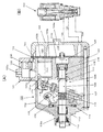
図1は、本発明の一実施態様に係る可変容量圧縮機(図1(A))と、その容量を制御するための容量制御弁(図1(B))を示している。図1において、可変容量圧縮機としての可変容量斜板式圧縮機100は、複数のシリンダボア101aを備えたシリンダブロック101と、シリンダブロック101の一端に設けられたフロントハウジング102と、バルブプレート103を介してシリンダブロック101の他端に設けられたリアハウジング104とを備えている。
Hereinafter, preferred embodiments of the present invention will be described with reference to the drawings.
FIG. 1 shows a variable capacity compressor (FIG. 1A) and a capacity control valve (FIG. 1B) for controlling the capacity according to an embodiment of the present invention. In FIG. 1, a variable capacity
シリンダブロック101とフロントハウジング102とによって画成されるクランク室105内を横断して、駆動軸106が配設されている。駆動軸106は斜板107に挿通されている。斜板107は、駆動軸106に固定されたロータ108と連結部109を介して結合し、駆動軸106とともに回転可能に、かつ、駆動軸106に対して傾角を可変可能に支持されている。ロータ108と斜板107との間に、斜板107を傾角減少方向へ向けて付勢するコイルバネ110が配設されている。斜板107を挟んでコイルバネ110の反対側には、最小傾角状態にある斜板107を傾角増大方向へ付勢する板バネ111が配設されている。この板バネ111は、後述の如く、本発明における、斜板107を傾角増大方向に付勢する複数の付勢手段としての板バネ部111a1、111a2、111a3を有する部材として構成されている。
A
駆動軸106の一端はフロントハウジング102のボス部102aを貫通してハウジング外まで延在しており、図示しない動力伝達装置を介して図示しない車両エンジン等の駆動源にベルト等を介して連結されている。駆動軸106とボス部102aとの間に軸封装置112が配設されている。駆動軸106は、ベアリング113、114、115、116によりラジアル方向及びスラスト方向に支持されている。
One end of the
シリンダボア101a内に、ピストン117が配設され、ピストン117の一端部の窪み117a内に収容された一対のシュー118が斜板107の外周部を相対摺動可能に挟持している。駆動軸106の回転は、斜板107とシュー118とを介してピストン117の往復動に変換される。
A
リアハウジング104内には、吸入室119と吐出室120とが形成されている。吸入室119は、バルブプレート103に形成された吸入孔103aと図示しない吸入弁とを介してシリンダボア101aに連通し、吐出室120は図示しない吐出弁とバルブプレート103に形成された吐出孔103bとを介してシリンダボア101aに連通している。吸入室119は吸入ポート104aを介して図示しない車両空調装置の蒸発器に接続している。
A
フロントハウジング102、シリンダブロック101、バルブプレート103、リアハウジング104は、協働して、駆動軸106、ロータ108、連結部109、斜板107、シュー118、ピストン117、シリンダボア101a、吸入弁、吐出弁等で形成される圧縮機構を収容するハウジングを形成している。
シリンダブロック101の外側にはマフラ121が配設されている。マフラ121は、シリンダブロック101とは別体の有底筒状の蓋部材122を、シリンダブロック101の外面に立設した筒状壁101bにシール部材を介して接合することにより、形成されている。蓋部材122に、吐出ポート122aが形成されている。吐出ポート122aは図示しない車両空調装置の凝縮器に接続している。
A
マフラ121を吐出室120に連通させる連通路123が、シリンダブロック101とバルブプレート103とリアハウジング104とにわたって形成されている。マフラ121と連通路123とは、吐出室120と吐出ポート122aとの間で延在する吐出通路を形成しており、マフラ121は当該吐出通路の途上に配設された拡張空間を形成している。そして、マフラ121の入口を開閉する逆止弁200がマフラ121内に配設されている。
A
上記フロントハウジング102、シリンダブロック101、バルブプレート103、リアハウジング104は図示しないガスケットを介して隣接し、複数の通しボルトを用いて一体に組付けられている。
The
リアハウジング104に容量制御弁300が取り付けられている。容量制御弁300は、吐出室120とクランク室105との間の連通路124の開度を調整し、クランク室105への吐出冷媒ガスの導入量を制御する。クランク室105内の冷媒ガスは、ベアリング115、116と駆動軸106との間の隙間と、シリンダブロック101に形成された空間125と、バルブプレート103に形成されたオリフィス孔103cとを介して吸入室119へ流入する。
A
容量制御弁300によりクランク室105の内圧を変化させ、可変容量斜板式圧縮機100の吐出容量を可変制御することができる。容量制御弁300は、外部信号に基づいて内蔵するソレノイドへの通電量を調整し、連通路126を介して容量制御弁300の感圧室に導入される吸入室119の内圧が所定値になるように、可変容量斜板式圧縮機100の吐出容量を可変制御し、また内蔵するソレノイドへの通電をOFFすることにより連通路124を強制開放して、可変容量斜板式圧縮機100の吐出容量を最小に制御する。容量制御弁300は、外部環境に応じて、吸入圧力を最適制御することができる。
By changing the internal pressure of the
容量制御弁300は、図2に示すように、バルブハウジング301に形成され、連通孔301aを介してクランク室105と連通する第1感圧室302と、第1感圧室302に一端が開口し、連通孔301bを介して吐出室120と連通する弁室303に他端が開口する弁孔301cと、弁室303に配設された一端が弁孔301cを開閉し他端部が支持孔301dに摺動可能に支持された円筒形状の弁体304と、第1感圧室302に配設され、連通孔301aを介してクランク室圧力を受圧し、内部を真空にしてバネを配設した感圧手段として機能するベローズ組立体305と、一端にベローズ組立体305が接離可能に連結し他端が弁体304の一端に固定された連結部306と、弁体304の他端が配設され連通孔301eを介して吸入室119に連通する第2感圧室307とを備えている。
As shown in FIG. 2, the
バルブハウジング301には弁体304の他端部を摺動可能に支持する支持孔301dが形成され、弁体304が支持孔301dに微小隙間で摺動可能に支持されることにより弁体304の他端は弁室303から遮断されている。
The
容量制御弁300は更に、弁体304と一体形成され弁体304から離隔する端部に可動鉄心308が圧入固定されたソレノイドロッド304aと、ソレノイドロッド304aを内挿し、所定隙間を隔てて可動鉄心308に対向配置された固定鉄心309と、固定鉄心309と可動鉄心308の間に配設され、可動鉄心308を開弁方向に付勢するばね310と、固定鉄心309と可動鉄心308とを内挿してソレノイドケース311に固定された非磁性体からなる筒状部材312と、筒状部材312を取り囲み、ソレノイドケース311に収容された電磁コイル313とから構成されている。
The
この容量制御弁300の動作については、ベローズ組立体305のベローズ有効面積Sbと、弁体304に作用する弁孔301c側より受けるクランク室105の圧力受圧面積Svと、第2感圧室307において弁体304に作用する吸入圧力の圧力受圧面積Srとをほぼ同一値に設定しているので、弁体304に作用する力は式(1)で表される。
Ps=〔−(1/Sb)・F(i)+(F+f)/Sb〕・・・(1)
ここで、
Ps:吸入室の圧力
Sb:ベローズ有効面積(=弁体に作用するクランク室の圧力受圧面積(Sv)=弁体に作用する吸入室の圧力受圧面積(Sr))
f:ばね310の付勢力
F:ベローズ付勢力
F(i):電磁力
である。
Regarding the operation of the
Ps = [− (1 / Sb) · F (i) + (F + f) / Sb] (1)
here,
Ps: suction chamber pressure Sb: bellows effective area (= pressure receiving area of crank chamber acting on valve body (Sv) = pressure receiving area of suction chamber acting on valve body (Sr))
f: biasing force F of the spring 310: bellows biasing force F (i): electromagnetic force.
また、容量制御弁300においては、吸入室圧力Psが式(1)で示される値よりも低いと、ベローズ305aが伸長して弁体304が弁座から離れて弁孔301cを開放し、第1感圧室302と弁室303とを弁孔301cを介して連通させ、吐出室120とクランク室105との間の連通路124を開放する。吐出室120の冷媒が連通路124を通ってクランク室105に供給され、クランク室圧力が上昇し、斜板107の傾角が減少して可変容量圧縮機100の吐出容量が減少し、吸入室圧力が上昇する。吸入室圧力が式(1)で示される値よりも高いと、ベローズ組立体305のベローズが収縮し弁体304が弁座に当接して弁孔301cを閉鎖し、第1感圧室302と弁室303との弁孔301cを介する連通を遮断して、吐出室120とクランク室105との間の連通路124を閉鎖する。クランク室105内の冷媒ガスが、ベアリング115、116と駆動軸106との間の隙間と、シリンダブロック101に形成された空間125と、バルブプレート103に形成されたオリフィス孔103cとを介して吸入室119へ流出してクランク室圧力が低下し、斜板107の傾角が増加して圧縮機100の吐出容量が増加し、吸入室圧力が低下する。ベローズ組立体305、連結部306および弁体304で構成する感圧機構が吸入室圧力を式(1)で示される値に自律制御する。ソレノイドロッド304a、可動鉄心308、固定鉄心309、ばね310、ソレノイドケース311、筒状部材312、電磁コイル313により構成される電磁アクチュエータが、電磁コイル313を流れる電流値iに応じて感圧機構の作動点を変化させる。
Further, in the
容量制御弁300では、電磁コイル313への通電量iが増加すると吸入室圧力が低下する制御特性が得られる。容量制御弁300においては、前述の感圧機構と電磁アクチュエータとが弁体304を駆動している。容量制御弁300が感圧機構を有することにより、吸入室圧力の制御精度が向上し、感圧機構の動作点を変化させる電磁アクチュエータとを有することにより、制御電流iに対して一義的に制御吸入室圧力を決定することが可能になる。
In the
また、ソレノイドへの通電をOFFすればバネ310の付勢力により弁体304が弁孔301cを開放して、吐出室120の冷媒が連通路124を通ってクランク室105に供給され、クランク室圧力が上昇して斜板107の傾角が減少し、可変容量圧縮機100の吐出容量が最小となる。
Further, when the energization to the solenoid is turned off, the
次に、図3〜図6を参照しながら、板バネ111について説明する。
本実施態様では、板バネ111は、図3、図4に示すように、周方向に3箇所の板バネ部111a1、111a2、111a3、3箇所のストッパ111bおよび3箇所の板バネ部111a1、111a2、111a3と3箇所のストッパ111bを連結する環状に形成された連結部111cが一体に連結されたものである。すなわち、この板バネ111は、本発明における、斜板107を傾角増大方向に付勢する複数の付勢手段としての3箇所の板バネ部111a1、111a2、111a3と、斜板107の機械的な最小傾角を規定する最小傾角規定手段としての3箇所のストッパ111bとを、連結手段としての連結部111cにより一体に連結した部材として構成されている。この板バネ111は、板バネ形成材(板バネ形成板)からプレス成形によって形成され、各板バネ部111a1、111a2、111a3以外の残部にストッパ111bと連結部111cが形成されている。なお、3箇所の板バネ部111a1、111a2、111a3は駆動軸106の周囲にほぼ等間隔に配置されている。
Next, the
In this embodiment, as shown in FIGS. 3 and 4, the
板バネ111は、図4に示すように、連結部111cの内径側部分111d(図3(A)に図示)が駆動軸106に挿通され、駆動軸106に形成された段差に当接することにより軸方向に位置決めされてスナップリング150により固定されている。ストッパ111bの先端に斜板107が当接することにより斜板107の機械的に規制される最小傾角(θmin)が規定される。最小傾角(θmin)は、例えば図6に示すように、駆動軸106の軸線に対して斜板107の面が直交する状態を0°としたとき、ほぼ0°(0°近傍の角度)に設定されており、この最小傾角(θmin)を狙って3箇所のストッパ111bの高さが設定される。
As shown in FIG. 4, the
また、各板バネ部111a1、111a2、111a3の先端側が斜板107に当接することにより斜板107を傾角増大方向に付勢する付勢力が作用するが、各板バネ部111a1、111a2、111a3の先端側が斜板107に当接する斜板107の傾角は各板バネにより異なるように設定されている。これは、図3(B)に示すように、連結部111cからの各板バネ部111a1、111a2、111a3の先端の軸方向高さを異なるように設定することにより確実に達成できる(h1>h2>h3)。
Further, the urging force for urging the
また、ストッパ111bの先端も連結部111cからの高さで管理されるため、最小傾角からの板バネ111の付勢力のばらつきが低減する。なお、ストッパ111bは板バネ部111a1、111a2、111a3の過度な撓みを規制する規制手段を兼ねているため、板バネ部111a1、111a2、111a3には過度な応力が作用しないようになっている。
Further, since the tip of the
板バネ111の付勢力は、例えば図5に示すようになる。例えば板バネ111の外径以上の押圧面を有する押圧体で板バネ111を押圧すると(押圧体が板バネ部111a1に当接したときを0とする)、板バネ部111a1の変位がx1までは板バネ部111a1のみがバネとして機能して付勢力が比例的に増大するが、x1を超えると板バネ部111a2も当接して板バネ部111a2の付勢力が加わり、付勢力増大の傾き(勾配)が大きくなる。さらに変位がx2を超えると、板バネ部111a3も当接して板バネ部111a3の付勢力が加わり、付勢力増大の勾配がさらに大きくなる。つまり、板バネ部による付勢数が増加することによりバネ定数が段階的に大きくなる特性を持つ。したがって、x1、x2を適切な位置に設定することにより、荷重特性を調整でき、付勢力の最適化を図ることができる。
The urging force of the
斜板107は所定の角度θ1より小さくなるとコイルバネ110と板バネ111により挟持され、両バネの合力は図6に示すようになる。図6において、θ1〜θ2の間は板バネ111a1のみがバネとして機能しており、θ2〜θ3の間は板バネ111a1と111a2がバネとして機能し、θ3〜θminの間はすべての板バネ111a1、111a2および111a3がバネとして機能している。なお、θ4は両バネの合力がゼロとなる角度であり、θ4以下では斜板107を傾角増大方向に付勢する付勢力が作用し、θ4を超えると斜板107を傾角減少方向に付勢する付勢力が作用する。
When the
このように、連結部111cからの高さが異なる板バネ部111a1、111a2、111a3の先端側が斜板107に順次当接し、付勢数が順次増加するように構成したことにより、板バネ111に、斜板107を傾角増大方向に付勢する付勢力として、きめ細かに調整された望ましい特性を持たせることが可能になる。
As described above, the leaf spring portions 111a1, 111a2, and 111a3 having different heights from the connecting
上記実施態様においては、各板バネ部の高さを異なるように設定したが、各板バネ部の高さを同じに設定して各板バネ部が当接する斜板側に段差を設け、各板バネ部が斜板の傾角が小さくなるに従い順次付勢数が増大するようにしてもよい。このようにすれば板バネ部の形成が容易となる。 In the above embodiment, the height of each leaf spring portion is set to be different, but the height of each leaf spring portion is set to be the same and a step is provided on the swash plate side where each leaf spring portion abuts. The number of biases may be increased sequentially as the inclination angle of the swash plate decreases. If it does in this way, formation of a leaf spring part will become easy.
また、上記実施態様では複数の付勢手段として上記実施態様では3つの場合を示したが、付勢手段は2つ以上であればいくつでもよい。例えば、図7は付勢手段が2つの場合、図8は付勢手段が4つの場合のバネ合力特性の例を示したもので、付勢数は付勢力調整の最適化を考慮して決定すればよい。 In the above embodiment, three cases are shown as a plurality of biasing means in the above embodiment, but any number of biasing means may be used as long as there are two or more. For example, FIG. 7 shows an example of a spring resultant force characteristic when there are two urging means, and FIG. 8 shows an example of the spring resultant force characteristic when there are four urging means, and the urging number is determined in consideration of optimization of urging force adjustment. do it.
また、上記実施態様では複数の板バネ部111a1、111a2、111a3の腕の長さをほぼ同じにして高さを変えたが、各板バネ部の腕の長さを異なるように設定して、それぞれバネ定数を異なるようにしてもよい。このように設定すれば、板バネ111のバネ特性の調整の自由度がさらに拡大され、付勢力の調整の最適化が容易に図れる。
Moreover, in the said embodiment, although the length of the arm of the several leaf | plate spring part 111a1, 111a2, 111a3 was substantially the same, and height was changed, it sets so that the length of the arm of each leaf | plate spring part may differ, Each spring constant may be different. With this setting, the degree of freedom in adjusting the spring characteristics of the
また、複数の付勢手段としては板バネに限定されない。例えば圧縮コイルバネを駆動軸の周囲に配置し、一端を斜板に当接させ、他端を連結部で連結してもよい。あるいは、同心上に配置された複数の圧縮コイルバネの中に駆動軸を挿通させ、一端を斜板に当接させ、他端を連結部で連結してもよい。 Further, the plurality of biasing means are not limited to leaf springs. For example, a compression coil spring may be disposed around the drive shaft, one end may be brought into contact with the swash plate, and the other end may be connected by a connecting portion. Alternatively, the drive shaft may be inserted into a plurality of concentric compression coil springs, one end abutted against the swash plate, and the other end connected by a connecting portion.
また、上記実施態様では、複数の板バネ部111a1、111a2、111a3は図3(A)に示したように駆動軸の周方向の向きに形成されているが、板バネ部の形成はこれに限定されるものではない。例えば各板バネ部の先端部が駆動軸の軸心に向かうように形成してもよいし、駆動軸から遠ざかる向きに形成してもよい。 In the above embodiment, the plurality of leaf spring portions 111a1, 111a2, and 111a3 are formed in the circumferential direction of the drive shaft as shown in FIG. It is not limited. For example, the tip of each leaf spring may be formed so as to face the axis of the drive shaft, or may be formed away from the drive shaft.
また、板バネ111が駆動軸106に対して回転しないように回転阻止構造を設けること。例えば駆動軸に溝を形成し、その溝に板バネ111の一部を係合させる構造を採ることもできる。
In addition, a rotation prevention structure is provided so that the
また、斜板107と駆動軸106との間にスリーブ、ヒンジボール等の斜板支持体を有する構造の場合には、その斜板支持体を板バネ部111a1、111a2、111a3で付勢するようにすることもできる。
In the case of a structure having a swash plate support such as a sleeve and a hinge ball between the
また、斜板とは別に、駆動軸とともに回転しない揺動板を設けた揺動板式の可変容量圧縮機においては、その揺動板を板バネ部111a1、111a2、111a3で付勢するようにすることもできる。 In addition, in an oscillating plate type variable capacity compressor provided with an oscillating plate that does not rotate together with the drive shaft separately from the swash plate, the oscillating plate is urged by leaf springs 111a1, 111a2, and 111a3. You can also
また、電磁クラッチを装着した可変容量圧縮機やクラッチレス圧縮機に本発明を適用することもできるし、モータで駆動される可変容量圧縮機、例えばモータ内蔵の可変容量圧縮機に本発明を適用することもできる。 In addition, the present invention can be applied to a variable capacity compressor or a clutchless compressor equipped with an electromagnetic clutch, or a variable capacity compressor driven by a motor, for example, a variable capacity compressor with a built-in motor. You can also
さらに、上記実施態様においては、被圧縮流体が冷媒である場合について説明したが、他の被圧縮流体であってもよい。また、被圧縮流体としての冷媒の種類も特に限定されず、冷媒としてR134aを使用する場合の他、二酸化炭素やその他の新冷媒に対応した可変容量圧縮機に共通して本発明を適用することが可能である。 Furthermore, in the said embodiment, although the case where the to-be-compressed fluid was a refrigerant | coolant was demonstrated, another to-be-compressed fluid may be sufficient. In addition, the type of refrigerant as the fluid to be compressed is not particularly limited, and the present invention is commonly applied to variable capacity compressors corresponding to carbon dioxide and other new refrigerants in addition to the case of using R134a as the refrigerant. Is possible.
本発明に係る可変容量圧縮機は、傾角可変の斜板を有するあらゆる圧縮機に適用可能であり、とくに、車両用空調装置に用いられる可変容量圧縮機として好適なものである。 The variable capacity compressor according to the present invention can be applied to any compressor having a swash plate with a variable tilt angle, and is particularly suitable as a variable capacity compressor used in a vehicle air conditioner.
100 可変容量圧縮機
101 シリンダブロック
101a シリンダボア
102 フロントハウジング
103 バルブプレート
104 リアハウジング
105 クランク室
106 駆動軸
107 斜板
108 ロータ
109 連結部
110 コイルバネ
111 複数の付勢手段を有する板バネ
111a1、111a2、111a3 斜板を傾角増大方向に付勢する付勢手段としての板バネ部
111b 斜板の機械的な最小傾角を規定する最小傾角規定手段としてのストッパ
111c 最小傾角規定手段と付勢手段との連結手段としての連結部
111d 連結部の内径側部分
117 ピストン
118 シュー
119 吸入室
120 吐出室
121 マフラ
122 蓋部材
123 連通路
150 スナップリング
200 逆止弁
300 容量制御弁
301 バルブハウジング
302 第1感圧室
303 弁室
304 弁体
304a ソレノイドロッド
305 ベローズ組立体
307 第2感圧室
308 可動鉄心
309 固定鉄心
311 ソレノイドケース
313 電磁コイル
DESCRIPTION OF
Claims (10)
Priority Applications (5)
| Application Number | Priority Date | Filing Date | Title |
|---|---|---|---|
| JP2008152521A JP5222447B2 (en) | 2008-06-11 | 2008-06-11 | Variable capacity compressor |
| US12/997,244 US20110091334A1 (en) | 2008-06-11 | 2009-06-02 | Variable Displacement Compressor |
| CN2009801223907A CN102057161A (en) | 2008-06-11 | 2009-06-02 | Variable displacement compressor |
| PCT/JP2009/060036 WO2009150959A1 (en) | 2008-06-11 | 2009-06-02 | Variable displacement compressor |
| DE112009001435T DE112009001435T5 (en) | 2008-06-11 | 2009-06-02 | Variable Displacement Compressor |
Applications Claiming Priority (1)
| Application Number | Priority Date | Filing Date | Title |
|---|---|---|---|
| JP2008152521A JP5222447B2 (en) | 2008-06-11 | 2008-06-11 | Variable capacity compressor |
Publications (2)
| Publication Number | Publication Date |
|---|---|
| JP2009299516A JP2009299516A (en) | 2009-12-24 |
| JP5222447B2 true JP5222447B2 (en) | 2013-06-26 |
Family
ID=41416670
Family Applications (1)
| Application Number | Title | Priority Date | Filing Date |
|---|---|---|---|
| JP2008152521A Expired - Fee Related JP5222447B2 (en) | 2008-06-11 | 2008-06-11 | Variable capacity compressor |
Country Status (5)
| Country | Link |
|---|---|
| US (1) | US20110091334A1 (en) |
| JP (1) | JP5222447B2 (en) |
| CN (1) | CN102057161A (en) |
| DE (1) | DE112009001435T5 (en) |
| WO (1) | WO2009150959A1 (en) |
Families Citing this family (9)
| Publication number | Priority date | Publication date | Assignee | Title |
|---|---|---|---|---|
| EP2549106B1 (en) * | 2010-03-16 | 2019-10-16 | Eagle Industry Co., Ltd. | Volume control valve |
| JP5697022B2 (en) * | 2010-12-14 | 2015-04-08 | サンデン株式会社 | Variable capacity compressor |
| EP2722524B1 (en) * | 2011-06-15 | 2016-10-26 | Eagle Industry Co., Ltd. | Capacity control valve |
| JP6495634B2 (en) * | 2014-12-02 | 2019-04-03 | サンデンホールディングス株式会社 | Variable capacity compressor |
| CN110462212B (en) | 2017-03-28 | 2021-05-07 | 伊格尔工业股份有限公司 | Capacity control valve |
| KR102278485B1 (en) | 2017-08-28 | 2021-07-16 | 이구루코교 가부시기가이샤 | solenoid valve |
| EP3951170A4 (en) | 2019-04-03 | 2022-11-23 | Eagle Industry Co., Ltd. | Capacity control valve |
| CN113646529A (en) * | 2019-04-03 | 2021-11-12 | 伊格尔工业股份有限公司 | Capacity control valve |
| EP3951174A4 (en) | 2019-04-03 | 2022-11-16 | Eagle Industry Co., Ltd. | Capacity control valve |
Family Cites Families (14)
| Publication number | Priority date | Publication date | Assignee | Title |
|---|---|---|---|---|
| JPS631774A (en) * | 1986-06-20 | 1988-01-06 | Toyota Autom Loom Works Ltd | Self-exciting vibration preventing mechanism for suction valve of rocking cam plate type compressor |
| US4815358A (en) * | 1988-01-27 | 1989-03-28 | General Motors Corporation | Balanced variable stroke axial piston machine |
| JPH0413425Y2 (en) * | 1988-04-28 | 1992-03-27 | ||
| JP2611382B2 (en) * | 1988-10-15 | 1997-05-21 | 株式会社豊田自動織機製作所 | Oscillating swash plate compressor |
| US5059097A (en) * | 1989-01-26 | 1991-10-22 | Diesel Kiki Co. Ltd. | Variable capacity wobble plate compressor |
| JPH06166845A (en) * | 1992-11-30 | 1994-06-14 | Pentel Kk | Water-base ink composition for ball-point pen |
| JP3125952B2 (en) * | 1993-04-08 | 2001-01-22 | 株式会社豊田自動織機製作所 | Variable capacity swash plate compressor |
| JP2932952B2 (en) * | 1994-12-07 | 1999-08-09 | 株式会社豊田自動織機製作所 | Clutchless variable displacement compressor |
| US5515768A (en) * | 1995-02-28 | 1996-05-14 | Caterpillar Inc. | Slipper holddown device for an axial piston pump |
| CN1162700A (en) * | 1996-02-20 | 1997-10-22 | 株式会社丰田自动织机制作所 | Variable capacity refrigerant compressor |
| JP3783434B2 (en) | 1998-04-13 | 2006-06-07 | 株式会社豊田自動織機 | Variable capacity swash plate compressor and air conditioning cooling circuit |
| JP3960117B2 (en) * | 2001-08-02 | 2007-08-15 | 株式会社豊田自動織機 | Variable capacity compressor and noise suppression method |
| DE10214276A1 (en) * | 2002-03-28 | 2003-10-16 | Bosch Gmbh Robert | Machine, especially generator |
| US6669184B2 (en) * | 2002-05-29 | 2003-12-30 | Visteon Global Technologies, Inc. | Composite wave ring spring |
-
2008
- 2008-06-11 JP JP2008152521A patent/JP5222447B2/en not_active Expired - Fee Related
-
2009
- 2009-06-02 DE DE112009001435T patent/DE112009001435T5/en not_active Ceased
- 2009-06-02 CN CN2009801223907A patent/CN102057161A/en active Pending
- 2009-06-02 US US12/997,244 patent/US20110091334A1/en not_active Abandoned
- 2009-06-02 WO PCT/JP2009/060036 patent/WO2009150959A1/en active Application Filing
Also Published As
| Publication number | Publication date |
|---|---|
| CN102057161A (en) | 2011-05-11 |
| US20110091334A1 (en) | 2011-04-21 |
| DE112009001435T5 (en) | 2011-05-05 |
| WO2009150959A1 (en) | 2009-12-17 |
| JP2009299516A (en) | 2009-12-24 |
Similar Documents
| Publication | Publication Date | Title |
|---|---|---|
| JP5222447B2 (en) | Variable capacity compressor | |
| JP6115393B2 (en) | Variable capacity swash plate compressor | |
| JP4700048B2 (en) | Capacity control valve | |
| JP4695032B2 (en) | Volume control valve for variable capacity compressor | |
| WO2018124156A1 (en) | Capacity control valve | |
| US9518568B2 (en) | Swash plate type variable displacement compressor | |
| JP6135521B2 (en) | Variable capacity swash plate compressor | |
| US9903352B2 (en) | Swash plate type variable displacement compressor | |
| JP4436295B2 (en) | Variable capacity compressor | |
| JPWO2017057160A1 (en) | Control valve for variable displacement compressor | |
| JP6028524B2 (en) | Variable capacity swash plate compressor | |
| JP2008202572A (en) | Capacity control valve of variable displacement compressor | |
| JP2015183614A (en) | Variable displacement swash plate compressor | |
| KR100462032B1 (en) | Control valve of variable displacement compressor | |
| JP4333042B2 (en) | Control valve for variable capacity compressor | |
| KR100428821B1 (en) | control valve of capacity variable type compressor | |
| JP6141930B2 (en) | Capacity control valve | |
| JP6194837B2 (en) | Variable capacity swash plate compressor | |
| JP2003035274A (en) | Control valve for variable displacement compressor | |
| JP4864657B2 (en) | Clutchless variable capacity compressor | |
| JP5164679B2 (en) | Variable capacity compressor | |
| JP5915511B2 (en) | Variable capacity swash plate compressor | |
| WO2019097841A1 (en) | Capacity control valve for clutch-equipped swash-plate-type variable capacity compressor | |
| JP5075425B2 (en) | Volume control valve for variable capacity compressor | |
| JP2010144638A (en) | Variable displacement compressor |
Legal Events
| Date | Code | Title | Description |
|---|---|---|---|
| A621 | Written request for application examination |
Free format text: JAPANESE INTERMEDIATE CODE: A621 Effective date: 20110610 |
|
| TRDD | Decision of grant or rejection written | ||
| A01 | Written decision to grant a patent or to grant a registration (utility model) |
Free format text: JAPANESE INTERMEDIATE CODE: A01 Effective date: 20130215 |
|
| A61 | First payment of annual fees (during grant procedure) |
Free format text: JAPANESE INTERMEDIATE CODE: A61 Effective date: 20130309 |
|
| FPAY | Renewal fee payment (event date is renewal date of database) |
Free format text: PAYMENT UNTIL: 20160315 Year of fee payment: 3 |
|
| R150 | Certificate of patent or registration of utility model |
Ref document number: 5222447 Country of ref document: JP Free format text: JAPANESE INTERMEDIATE CODE: R150 Free format text: JAPANESE INTERMEDIATE CODE: R150 |
|
| S533 | Written request for registration of change of name |
Free format text: JAPANESE INTERMEDIATE CODE: R313533 |
|
| R350 | Written notification of registration of transfer |
Free format text: JAPANESE INTERMEDIATE CODE: R350 |
|
| R250 | Receipt of annual fees |
Free format text: JAPANESE INTERMEDIATE CODE: R250 |
|
| R250 | Receipt of annual fees |
Free format text: JAPANESE INTERMEDIATE CODE: R250 |
|
| R250 | Receipt of annual fees |
Free format text: JAPANESE INTERMEDIATE CODE: R250 |
|
| R250 | Receipt of annual fees |
Free format text: JAPANESE INTERMEDIATE CODE: R250 |
|
| LAPS | Cancellation because of no payment of annual fees |