EP3961003A1 - Rocker arm assembly for engine braking - Google Patents
Rocker arm assembly for engine braking Download PDFInfo
- Publication number
- EP3961003A1 EP3961003A1 EP21166764.7A EP21166764A EP3961003A1 EP 3961003 A1 EP3961003 A1 EP 3961003A1 EP 21166764 A EP21166764 A EP 21166764A EP 3961003 A1 EP3961003 A1 EP 3961003A1
- Authority
- EP
- European Patent Office
- Prior art keywords
- rocker arm
- valve
- assembly
- exhaust valve
- oil
- Prior art date
- Legal status (The legal status is an assumption and is not a legal conclusion. Google has not performed a legal analysis and makes no representation as to the accuracy of the status listed.)
- Pending
Links
Images


Classifications
-
- F—MECHANICAL ENGINEERING; LIGHTING; HEATING; WEAPONS; BLASTING
- F01—MACHINES OR ENGINES IN GENERAL; ENGINE PLANTS IN GENERAL; STEAM ENGINES
- F01L—CYCLICALLY OPERATING VALVES FOR MACHINES OR ENGINES
- F01L13/00—Modifications of valve-gear to facilitate reversing, braking, starting, changing compression ratio, or other specific operations
- F01L13/06—Modifications of valve-gear to facilitate reversing, braking, starting, changing compression ratio, or other specific operations for braking
-
- F—MECHANICAL ENGINEERING; LIGHTING; HEATING; WEAPONS; BLASTING
- F01—MACHINES OR ENGINES IN GENERAL; ENGINE PLANTS IN GENERAL; STEAM ENGINES
- F01L—CYCLICALLY OPERATING VALVES FOR MACHINES OR ENGINES
- F01L1/00—Valve-gear or valve arrangements, e.g. lift-valve gear
- F01L1/12—Transmitting gear between valve drive and valve
- F01L1/18—Rocking arms or levers
- F01L1/181—Centre pivot rocking arms
-
- F—MECHANICAL ENGINEERING; LIGHTING; HEATING; WEAPONS; BLASTING
- F01—MACHINES OR ENGINES IN GENERAL; ENGINE PLANTS IN GENERAL; STEAM ENGINES
- F01L—CYCLICALLY OPERATING VALVES FOR MACHINES OR ENGINES
- F01L1/00—Valve-gear or valve arrangements, e.g. lift-valve gear
- F01L1/20—Adjusting or compensating clearance
- F01L1/22—Adjusting or compensating clearance automatically, e.g. mechanically
- F01L1/24—Adjusting or compensating clearance automatically, e.g. mechanically by fluid means, e.g. hydraulically
- F01L1/2416—Adjusting or compensating clearance automatically, e.g. mechanically by fluid means, e.g. hydraulically by means of a hydraulic adjusting device attached to an articulated rocker
-
- F—MECHANICAL ENGINEERING; LIGHTING; HEATING; WEAPONS; BLASTING
- F01—MACHINES OR ENGINES IN GENERAL; ENGINE PLANTS IN GENERAL; STEAM ENGINES
- F01L—CYCLICALLY OPERATING VALVES FOR MACHINES OR ENGINES
- F01L1/00—Valve-gear or valve arrangements, e.g. lift-valve gear
- F01L1/26—Valve-gear or valve arrangements, e.g. lift-valve gear characterised by the provision of two or more valves operated simultaneously by same transmitting-gear; peculiar to machines or engines with more than two lift-valves per cylinder
-
- F—MECHANICAL ENGINEERING; LIGHTING; HEATING; WEAPONS; BLASTING
- F01—MACHINES OR ENGINES IN GENERAL; ENGINE PLANTS IN GENERAL; STEAM ENGINES
- F01L—CYCLICALLY OPERATING VALVES FOR MACHINES OR ENGINES
- F01L13/00—Modifications of valve-gear to facilitate reversing, braking, starting, changing compression ratio, or other specific operations
- F01L13/06—Modifications of valve-gear to facilitate reversing, braking, starting, changing compression ratio, or other specific operations for braking
- F01L13/065—Compression release engine retarders of the "Jacobs Manufacturing" type
-
- F—MECHANICAL ENGINEERING; LIGHTING; HEATING; WEAPONS; BLASTING
- F01—MACHINES OR ENGINES IN GENERAL; ENGINE PLANTS IN GENERAL; STEAM ENGINES
- F01L—CYCLICALLY OPERATING VALVES FOR MACHINES OR ENGINES
- F01L1/00—Valve-gear or valve arrangements, e.g. lift-valve gear
- F01L1/20—Adjusting or compensating clearance
- F01L1/22—Adjusting or compensating clearance automatically, e.g. mechanically
- F01L1/24—Adjusting or compensating clearance automatically, e.g. mechanically by fluid means, e.g. hydraulically
- F01L2001/2444—Details relating to the hydraulic feeding circuit, e.g. lifter oil manifold assembly [LOMA]
-
- F—MECHANICAL ENGINEERING; LIGHTING; HEATING; WEAPONS; BLASTING
- F01—MACHINES OR ENGINES IN GENERAL; ENGINE PLANTS IN GENERAL; STEAM ENGINES
- F01L—CYCLICALLY OPERATING VALVES FOR MACHINES OR ENGINES
- F01L2760/00—Control of valve gear to facilitate reversing, starting, braking of four stroke engines
- F01L2760/003—Control of valve gear to facilitate reversing, starting, braking of four stroke engines for switching to compressor action in order to brake
- F01L2760/004—Control of valve gear to facilitate reversing, starting, braking of four stroke engines for switching to compressor action in order to brake whereby braking is exclusively produced by compression in the cylinders
-
- F—MECHANICAL ENGINEERING; LIGHTING; HEATING; WEAPONS; BLASTING
- F02—COMBUSTION ENGINES; HOT-GAS OR COMBUSTION-PRODUCT ENGINE PLANTS
- F02D—CONTROLLING COMBUSTION ENGINES
- F02D13/00—Controlling the engine output power by varying inlet or exhaust valve operating characteristics, e.g. timing
- F02D13/02—Controlling the engine output power by varying inlet or exhaust valve operating characteristics, e.g. timing during engine operation
- F02D13/04—Controlling the engine output power by varying inlet or exhaust valve operating characteristics, e.g. timing during engine operation using engine as brake
Definitions
- the present disclosure relates generally to a rocker arm assembly for use in a valve train assembly and more particularly to a rocker arm assembly that provides a compression brake function.
- Compression engine brakes can be used as auxiliary brakes, in addition to wheel brakes, on relatively large vehicles, for example trucks, powered by heavy or medium duty diesel engines.
- a compression engine braking system is arranged, when activated, to provide an additional opening of an engine cylinder's exhaust valve when the piston in that cylinder is near a top-dead-center position of its compression stroke so that compressed air can be released through the exhaust valve. This causes the engine to function as a power consuming air compressor, which slows the vehicle.
- the exhaust valve is actuated by a rocker arm, which engages the exhaust valve by means of a valve bridge.
- the rocker arm rocks in response to a cam on a rotating cam shaft and presses down on the valve bridge which itself presses down on the exhaust valve to open it.
- a hydraulic lash adjuster may also be provided in the valve train assembly to remove any lash or gap that develops between the components in the valve train assembly.
- An exhaust valve rocker arm assembly operable in a combustion engine mode and an engine braking mode can include a rocker shaft and a rocker arm.
- the rocker shaft can define a pressurized oil supply conduit.
- the rocker arm can receive the rocker shaft and is configured to rotate around the rocker shaft.
- the rocker arm can have an oil supply passage defined therein.
- a valve bridge can engage a first exhaust valve and a second exhaust valve.
- a hydraulic lash adjuster assembly can be disposed on the rocker arm having a first plunger body movable between a first position and a second position. In the first position, the first plunger body extends rigidly for cooperative engagement with the valve bridge.
- An accumulator assembly can be disposed in the rocker arm and include an accumulator piston that translates within the accumulator piston housing between closed and open positions.
- the accumulator assembly is configured to store a predetermined amount of oil when the first plunger body moves toward the first position.
- pressurized oil is communicated through the pressurized oil supply conduit, through the rocker arm oil supply passage and against the actuator.
- the first plunger occupies the first position and acts on the valve bridge during rotation of the rocker arm to a first angle opening the first exhaust valve a predetermined distance while the second exhaust valve remains closed.
- the accumulator assembly further comprises an accumulator spring that biases the accumulator piston toward the closed position. In the closed position, oil is inhibited from entering the accumulator piston housing.
- the accumulator assembly can further define a release hole formed in the rocker arm that fluidly connects with the piston housing. Oil is released from the piston housing through the release hole upon the accumulator piston translating a predetermined amount.
- the exhaust valve rocker arm assembly can further comprise an oil discharge circuit.
- the oil discharge circuit can be configured to selectively depressurize oil under the disk portion of the needle.
- a spigot can be disposed on the rocker arm. In the engine braking mode, subsequent to the opening of the first valve the predetermined distance, further rotation of the rocker arm causes the spigot to move the valve bridge and open the second valve while further opening the first valve.
- the oil discharge circuit can be collectively defined by a first connecting passage and an outlet passage defined in the rocker arm and a pass-through channel defined in the spigot.
- the first connecting passage can connect a bore defined in the rocker arm that receives the disk portion with a spigot receiving passage that receives the spigot.
- the spigot can be configured to translate relative to the rocker arm along the spigot receiving passage. A predetermined rotation of the rocker arm will align the first connecting passage, the pass-through channel and the outlet passage and depressurize oil from under the disk portion of the needle.
- the hydraulic lash adjuster assembly can further comprise a second plunger body that is at least partially received by the first plunger body.
- the second plunger body can define a valve seat.
- a check valve can be disposed on the rocker arm and have an actuator that selectively releases pressure in the hydraulic lash adjuster.
- the actuator can further comprise a needle having a longitudinal pin portion and a disk portion.
- the check valve can be disposed between the first and second plunger bodies.
- the check valve can further comprise a check ball that selectively seats against the valve seat on the second plunger body.
- An exhaust valve rocker arm assembly operable in a combustion engine mode and an engine braking mode includes a rocker shaft that defines a pressurized oil supply conduit.
- a rocker arm can receive the rocker shaft and be configured to rotate around the rocker shaft.
- the rocker arm can have an oil supply passage defined therein.
- a valve bridge can engage a first exhaust valve and a second exhaust valve. The valve bridge can translate in a linear direction upon rotation of the rocker arm.
- a first plunger body can be movable between a first position and a second position. In the first position the first plunger body extends rigidly for cooperative engagement with the valve bridge.
- a check valve can be disposed on the rocker arm and have an actuator that selectively releases pressure acting on the first plunger body.
- An oil discharge circuit can be configured to selectively depressurize oil under the disk portion of the actuator.
- the rocker arm In the engine braking mode the rocker arm is configured to rotate (i) a first predetermined angle wherein pressurized oil is communicated through the pressurized oil supply conduit, through the rocker arm oil supply passage and against the actuator.
- the first plunger occupies the first position and acts on the valve bridge opening the first valve a predetermined distance while the second valve remains closed.
- the rocker arm continues to rotate (ii) a second predetermined angle wherein the oil discharge circuit opens releasing oil pressure from under the disk portion of the actuator, and (iii) a third predetermined angle wherein the rocker arm oil supply passage disconnects from the pressurized oil circuit.
- An accumulator assembly can be disposed in the rocker arm and include an accumulator piston that translates within the accumulator piston housing between closed and open positions.
- the accumulator assembly is configured to store a predetermined amount of oil when the first plunger body moves toward the first position.
- a spigot can be disposed on the rocker arm. In the engine braking mode, subsequent to opening of the first valve the predetermined distance, further rotation of the rocker arm can cause the spigot to move the valve bridge and open the second valve while further opening the first valve.
- the oil discharge circuit is collectively defined by a first connecting passage and an outlet passage defined in the rocker arm and a pass-through channel defined in the spigot.
- the first connecting passage can connect a bore defined in the rocker arm that receives the disk portion with a spigot receiving passage that receives the spigot.
- the spigot can be configured to translate along the spigot receiving passage relative to the rocker arm. A predetermined rotation of the rocker arm will align the first connecting passage, the pass-through channel and the outlet passage and depressurize oil from under the disk portion of the needle.
- the hydraulic lash adjuster assembly can further comprise a second plunger body that is at least partially received by the first plunger body.
- the second plunger body can define a valve seat.
- the check valve can be disposed between the first and second plunger bodies.
- the check valve can further comprise a check ball that selectively seats against the valve seat on the second plunger body.
- the spigot can be configured to slidably translate along the spigot receiving passage prior to moving the bridge portion.
- a partial valve train assembly constructed in accordance to one example of the present disclosure is shown and generally identified at reference 10.
- the partial valve train assembly 10 utilizes engine braking and is shown configured for use in a three-cylinder bank portion of a six-cylinder engine. It will be appreciated however that the present teachings are not so limited. In this regard, the present disclosure may be used in any valve train assembly that utilizes engine braking.
- the partial valve train assembly 10 can include a rocker assembly housing 12 that supports a rocker arm assembly 20 having a series of intake valve rocker arm assemblies 28 and a series of exhaust valve rocker arm assemblies 30.
- a rocker shaft 34 is received by the rocker housing 30.
- the rocker shaft 34 cooperates with the rocker arm assembly 20 and more specifically to the exhaust valve rocker arm assemblies 30 to communicate oil to the exhaust valve rocker arm assemblies 30 during engine braking.
- the exhaust valve rocker arm assembly 30 can generally include a rocker arm 40, a valve bridge 42, an accumulator assembly 43, a spigot assembly 44 and a capsule or hydraulic lash adjuster (HLA) assembly 46.
- the valve bridge 42 is a guided valve bridge that engages a first and second exhaust valve 50 and 52 ( FIG. 3 ) associated with a cylinder of an engine (not shown). The first and second exhaust valves 50 and 52 cooperate with and are moved by the valve bridge 42.
- the valve bridge 42 includes a movable member 48 disposed therein. The valve bridge 42 is configured to move in a linear direction upon rotation of the rocker arm 40.
- valve bridge is configured to move generally vertically as viewed in FIG. 3 .
- Other configurations are contemplated.
- a corresponding elephant foot or E-foot may be associated with one or both exhaust valves 50, 52.
- a pushrod 54 ( FIG. 3 ) moves upward and downward based on a lift profile of a cam shaft (not shown). Upward movement of the pushrod 54 pushes an arm 56 fixed to the rocker arm 40 and in turn causes the rocker arm 40 to rotate counter-clockwise around the rocker shaft 34.
- the HLA assembly 46 can comprise a plunger assembly 60 including a first plunger body 62 and a second plunger body 64.
- the second plunger body 64 can be partially received by the first plunger body 62.
- the plunger assembly 60 is received by a first bore 66 defined in the rocker arm 40.
- the first plunger body 64 can have a first closed end 68 that defines a first spigot 70, which is received in a first socket 72 that acts against the valve bridge 42.
- the second plunger body 64 has an opening that defines a valve seat 76 ( FIG. 4 ).
- a check ball assembly 80 can be positioned between the first and second plunger bodies 62 and 64.
- the check ball assembly 80 can include a first biasing member 82, a cage 84, a second biasing member 86 and a check ball 90.
- a snap ring 92 nests in a radial groove provided in the first bore 66 of the rocker arm 40. The snap ring 92 retains the first plunger body 62 in the first bore 66.
- An actuator or needle 100 is received in a second bore 104 of the rocker arm 40.
- the needle 100 acts as an actuator that selectively releases pressure in the HLA assembly 46.
- the needle 100 includes a longitudinal pin portion 110 and an upper disk portion 112.
- a cap 116 is fixed to the rocker arm 40 with a plurality of fasteners 118 to cover the first bore 136 and the second bore 104 to capture the components therein.
- the biasing member 120 acts between the cap 116 and the upper disk portion 112 of the needle 100. In the example shown, the biasing member 120 biases the needle 100 downwardly as viewed in FIG. 3 .
- the spigot assembly 44 can generally include a lost motion shaft or second spigot 130 having a distal end that is received by a second socket 132 and a proximal end that extends into a third bore 136 defined in the rocker arm 40.
- a collar 138 can extend from an intermediate portion of the second spigot 130.
- the second spigot 130 can extend through the third bore formed through the rocker arm 40.
- the cap 116 captures a biasing member 144 therein.
- the biasing member 144 acts between the cap 116 and a snap ring 148 fixed to the proximal end of the second spigot 130.
- the second spigot 130 remains in contact with the rocker arm 40 and is permitted to translate along its axis within the third bore 136.
- the rocker shaft 34 can define a central pressurized oil supply conduit 152, a vent oil passage or conduit 154, a lubrication conduit 156 and a lash adjuster oil conduit 180.
- the vent oil conduit 154 can have a vent lobe 157 extending generally parallel to an axis of the rocker shaft 34 and transverse to the vent oil conduit 154.
- a connecting passage 158 FIG. 12 ) can connect the central pressurized oil supply conduit 152 with an oil supply passage 160 defined in the rocker arm 40.
- the lash adjuster oil conduit 180 can be used to supply oil to the HLA assembly 46.
- the oil discharge circuit 210 is collectively defined by a first connecting passage 220, a second connecting passage 222, an outlet passage 224 and a pass-through channel 230.
- the first connecting passage 220, second connecting passage 222 and the outlet passage 224 are defined in the rocker arm 40.
- the pass-through channel 230 is defined through the second spigot 130.
- the first connecting passage 220 and the second connecting passage 222 connect the second bore 104 of the rocker arm 40 that receives the upper disk portion 1 12 of the needle 100 with the third bore 136 of the rocker arm 40 that receives the second spigot 130.
- the pass-through channel 230 aligns with the second connecting passage 222 and the outlet passage 224 (see FIG. 6 ) allowing oil to depressurize from below the upper disk portion 1 12 and ultimately flow out of the outlet passage 224.
- the pressurized oil supply conduit 152, the connecting passage 158 and the oil supply passage 160 cooperate to supply pressurized oil to the second bore 104 to urge the upper disk portion 112 of the needle 100 upward.
- the vent lobe 157 will align with the oil supply passage 160 causing oil to be vented away from the second bore 104 through the vent oil conduit 154.
- oil is also drained through the discharge oil circuit 210.
- the second spring 120 will urge the needle 100 downward such that the longitudinal pin 110 will act against the ball 90 and move the ball away from the valve seat 76.
- the exhaust rocker arm assembly 30 can operate in a default combustion engine mode with engine braking off ( FIG. 3 ) and an engine braking mode ( FIGS. 4-6 ).
- an oil control valve 152 is closed (not energized).
- the oil supply passage 160 defined in the rocker arm 40 has a low pressure level.
- Other pressures may be used.
- the biasing member 120 will force the needle 100 in a downward direction causing the longitudinal pin portion 110 to urge the ball 90 away from the valve seat 76.
- the check ball assembly 80 is therefore open causing the HLA assembly 46 to become "soft" and not influencing a downward force upon the valve bridge 42.
- FIG. 4 operation of the exhaust valve rocker arm assembly 30 in the engine braking mode will be described.
- oil pressure is increased in oil supply passage 160 causing the needle 100 to move upward against the bias of the biasing member 120.
- the HLA assembly 46 acts as a no-return valve with the first plunger body 62 rigidly extending toward the valve bridge 42.
- the discharge oil circuit 210 is blocked because the pass-through channel 230 of the second spigot 130 is not aligned with the second connecting passage 222 and the outlet passage 224.
- FIG. 4A is a plot of cam degrees versus valve lift for the exhaust valve rocker arm assembly of the present teachings and identifying the position of FIG. 4 on the base circle.
- the rocker arm 40 has rotated further counter-clockwise around the rocker shaft 34.
- the rocker arm 40 has rotated 2.72 degrees.
- the first spigot 70 will force the first socket 72 against the valve bridge 42 causing the first valve 50 to move off a first valve seat 170.
- the first valve 50 moves off the first valve seat 170 a distance of 2.85mm.
- the second valve 52 remains closed against a second valve seat 172. The collar 138 on the second spigot 130, while traveling toward the rocker arm 40, has not yet reached the rocker arm 40.
- FIG. 5 the second spigot 130 has moved about 2mm of lost motion and remains in contact (through the second socket 132) with the rocker arm 40.
- the pass-through channel 230 of the second spigot 130 starts to put in communication the first and second connecting passages 220 and 222 with the outlet passage 224. From this position up, the oil from under the upper disk portion 1 12 of the needle 100 is flowing out the oil discharge circuit 210.
- the longitudinal pin 110 cannot be pushed down because the force of the biasing member 120 is lower than the force generated inside the HLA assembly 46 keeping the check ball assembly 80 closed.
- the oil supply passage 160 remains in communication with the connecting passage 158.
- FIG. 5A is a plot of cam degrees versus valve lift for the exhaust valve rocker arm assembly of the present teachings and identifying the position of FIG. 5 with the lost motion shaft at 2 mm of lost motion.
- the rocker arm 40 has rotated further counter-clockwise around the rocker shaft 34.
- the rocker arm 40 has rotated 4.41 degrees.
- the HLA assembly 46 remains rigid and the first spigot 70 continues to force the first socket 72 against the valve bridge 42 causing the first valve 50 to move further off the first valve seat 170.
- the first valve 50 moves off the first valve seat 170 a distance of 4.09mm. It will be appreciated that other distances (and degrees of rotation of the rocker arm 40) are contemplated.
- the collar 138 has made contact with the rocker arm 40 (lost motion has bottomed) and both the first and second valves 50 and 52 will be opened concurrently.
- the pass-through channel 230 is fully aligned with the first and second connecting passages 220 and 222 and the outlet passage 230 allowing oil from under the upper disk portion 112 of the needle 100 to depressurize out through the oil discharge circuit 210.
- the longitudinal pin 110 cannot be pushed down because the force of the biasing member 120 is lower than the force generated inside the HLA assembly 46 keeping the check ball assembly 80 closed.
- the oil supply passage 160 remains in communication with the connecting passage 158.
- FIG. 6A is a plot of cam degrees versus valve lift for the exhaust valve rocker arm assembly of the present teachings and identifying the position of FIG. 6 when the lost motion shaft has bottomed.
- the rocker arm 40 has rotated further counter-clockwise around the rocker shaft 34.
- the rocker arm 40 has rotated 8.82 degrees and the bridge 42 is in a horizontal position.
- the HLA assembly 46 remains rigid.
- the second spigot 130 urges the bridge 42 downward to open the first and second valves 50 and 52 off their respective valve seats 170 and 172.
- the first and second valves 50 and 52 have the same lift and are moved off their valve seats 170 and 172 a distance of 9.1 mm. It will be appreciated that other distances (and degrees of rotation of the rocker arm 40) are contemplated.
- FIG. 7A is a plot of cam degrees versus valve lift for the exhaust valve rocker arm assembly of the present teachings and identifying the position of FIG. 7 with the bridge in a horizontal position.
- the rocker arm 40 has rotated further counter-clockwise around the rocker shaft 34.
- the rocker arm 40 has rotated 12.9 degrees.
- the rocker arm 40 has rotated 12.9 degrees and the first and second valves 50 and 52 are at maximum lift off their valve seats 170 and 172.
- the first and second valves 50 and 52 are displaced 15.2 mm off their respective valve seats 170 and 172.
- the oil supply passage 160 in the rocker arm 40 is fully disconnected from the connecting passage 158 of the central pressurized oil supply conduit 152 and is now connected to the vent oil conduit 154 by way of the vent lobe 157.
- FIG. 8A is a plot of cam degrees versus valve lift for the exhaust valve rocker arm assembly of the present teachings and identifying the position of FIG. 8 with the valves at full lift.
- FIG. 9A is a plot of cam degrees versus valve lift for the exhaust valve rocker arm assembly of the present teachings and identifying the position of FIG. 9 during initial valve closure.
- FIG. 10A is a plot of cam degrees versus valve lift for the exhaust valve rocker arm assembly of the present teachings and identifying the position of FIG. 10 during further valve closure.
- the accumulator assembly 43 generally includes an accumulator piston 210, an accumulator spring 212, an accumulator snap ring 218 and an accumulator washer 220.
- the accumulator piston 210 slidably translates within a piston housing 226 that defines a release hole 230.
- the piston housing 226 provides an additional oil volume on the rocker arm 40.
- the accumulator piston 210 is normally pushed to its maximum extension (closed position) by the accumulator spring 212.
- a predetermined volume of oil is pushed into the piston housing 226 against the accumulator piston 210, moving the accumulator piston to an open position.
- the accumulator piston 210 is configured to accumulate a limited amount of oil. Beyond the predetermined amount, any additional oil volume generated by an extended collapsing stroke of the plunger assembly 60 will push the accumulator piston 210 backward (leftward as viewed in FIG. 3A ) until translating beyond the release hole 230. This additional oil is released through the release hole 230.
Abstract
Description
- The present disclosure relates generally to a rocker arm assembly for use in a valve train assembly and more particularly to a rocker arm assembly that provides a compression brake function.
- Compression engine brakes can be used as auxiliary brakes, in addition to wheel brakes, on relatively large vehicles, for example trucks, powered by heavy or medium duty diesel engines. A compression engine braking system is arranged, when activated, to provide an additional opening of an engine cylinder's exhaust valve when the piston in that cylinder is near a top-dead-center position of its compression stroke so that compressed air can be released through the exhaust valve. This causes the engine to function as a power consuming air compressor, which slows the vehicle.
- In a typical valve train assembly used with a compression engine brake, the exhaust valve is actuated by a rocker arm, which engages the exhaust valve by means of a valve bridge. The rocker arm rocks in response to a cam on a rotating cam shaft and presses down on the valve bridge which itself presses down on the exhaust valve to open it. A hydraulic lash adjuster may also be provided in the valve train assembly to remove any lash or gap that develops between the components in the valve train assembly.
- The background description provided herein is for the purpose of generally presenting the context of the disclosure. Work of the presently named inventors, to the extent it is described in this background section, as well as aspects of the description that may not otherwise qualify as prior art at the time of filing, are neither expressly nor impliedly admitted as prior art against the present disclosure.
- An exhaust valve rocker arm assembly operable in a combustion engine mode and an engine braking mode can include a rocker shaft and a rocker arm. The rocker shaft can define a pressurized oil supply conduit. The rocker arm can receive the rocker shaft and is configured to rotate around the rocker shaft. The rocker arm can have an oil supply passage defined therein. A valve bridge can engage a first exhaust valve and a second exhaust valve. A hydraulic lash adjuster assembly can be disposed on the rocker arm having a first plunger body movable between a first position and a second position. In the first position, the first plunger body extends rigidly for cooperative engagement with the valve bridge. An accumulator assembly can be disposed in the rocker arm and include an accumulator piston that translates within the accumulator piston housing between closed and open positions. The accumulator assembly is configured to store a predetermined amount of oil when the first plunger body moves toward the first position. In the engine braking mode, pressurized oil is communicated through the pressurized oil supply conduit, through the rocker arm oil supply passage and against the actuator. The first plunger occupies the first position and acts on the valve bridge during rotation of the rocker arm to a first angle opening the first exhaust valve a predetermined distance while the second exhaust valve remains closed.
- According to other features, the accumulator assembly further comprises an accumulator spring that biases the accumulator piston toward the closed position. In the closed position, oil is inhibited from entering the accumulator piston housing. The accumulator assembly can further define a release hole formed in the rocker arm that fluidly connects with the piston housing. Oil is released from the piston housing through the release hole upon the accumulator piston translating a predetermined amount.
- According to other features, the exhaust valve rocker arm assembly can further comprise an oil discharge circuit. The oil discharge circuit can be configured to selectively depressurize oil under the disk portion of the needle. A spigot can be disposed on the rocker arm. In the engine braking mode, subsequent to the opening of the first valve the predetermined distance, further rotation of the rocker arm causes the spigot to move the valve bridge and open the second valve while further opening the first valve.
- According to additional features, the oil discharge circuit can be collectively defined by a first connecting passage and an outlet passage defined in the rocker arm and a pass-through channel defined in the spigot. The first connecting passage can connect a bore defined in the rocker arm that receives the disk portion with a spigot receiving passage that receives the spigot. The spigot can be configured to translate relative to the rocker arm along the spigot receiving passage. A predetermined rotation of the rocker arm will align the first connecting passage, the pass-through channel and the outlet passage and depressurize oil from under the disk portion of the needle.
- According to still other features, the hydraulic lash adjuster assembly can further comprise a second plunger body that is at least partially received by the first plunger body. The second plunger body can define a valve seat. A check valve can be disposed on the rocker arm and have an actuator that selectively releases pressure in the hydraulic lash adjuster. The actuator can further comprise a needle having a longitudinal pin portion and a disk portion. The check valve can be disposed between the first and second plunger bodies. The check valve can further comprise a check ball that selectively seats against the valve seat on the second plunger body.
- An exhaust valve rocker arm assembly operable in a combustion engine mode and an engine braking mode according to another example of the present disclosure includes a rocker shaft that defines a pressurized oil supply conduit. A rocker arm can receive the rocker shaft and be configured to rotate around the rocker shaft. The rocker arm can have an oil supply passage defined therein. A valve bridge can engage a first exhaust valve and a second exhaust valve. The valve bridge can translate in a linear direction upon rotation of the rocker arm. A first plunger body can be movable between a first position and a second position. In the first position the first plunger body extends rigidly for cooperative engagement with the valve bridge. A check valve can be disposed on the rocker arm and have an actuator that selectively releases pressure acting on the first plunger body. An oil discharge circuit can be configured to selectively depressurize oil under the disk portion of the actuator. In the engine braking mode the rocker arm is configured to rotate (i) a first predetermined angle wherein pressurized oil is communicated through the pressurized oil supply conduit, through the rocker arm oil supply passage and against the actuator. The first plunger occupies the first position and acts on the valve bridge opening the first valve a predetermined distance while the second valve remains closed. The rocker arm continues to rotate (ii) a second predetermined angle wherein the oil discharge circuit opens releasing oil pressure from under the disk portion of the actuator, and (iii) a third predetermined angle wherein the rocker arm oil supply passage disconnects from the pressurized oil circuit.
- An accumulator assembly can be disposed in the rocker arm and include an accumulator piston that translates within the accumulator piston housing between closed and open positions. The accumulator assembly is configured to store a predetermined amount of oil when the first plunger body moves toward the first position. A spigot can be disposed on the rocker arm. In the engine braking mode, subsequent to opening of the first valve the predetermined distance, further rotation of the rocker arm can cause the spigot to move the valve bridge and open the second valve while further opening the first valve.
- According to still other features, the oil discharge circuit is collectively defined by a first connecting passage and an outlet passage defined in the rocker arm and a pass-through channel defined in the spigot. The first connecting passage can connect a bore defined in the rocker arm that receives the disk portion with a spigot receiving passage that receives the spigot. The spigot can be configured to translate along the spigot receiving passage relative to the rocker arm. A predetermined rotation of the rocker arm will align the first connecting passage, the pass-through channel and the outlet passage and depressurize oil from under the disk portion of the needle. The hydraulic lash adjuster assembly can further comprise a second plunger body that is at least partially received by the first plunger body. The second plunger body can define a valve seat. The check valve can be disposed between the first and second plunger bodies. The check valve can further comprise a check ball that selectively seats against the valve seat on the second plunger body. The spigot can be configured to slidably translate along the spigot receiving passage prior to moving the bridge portion.
- The present disclosure will become more fully understood from the detailed description and the accompanying drawings, wherein:
-
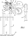
FIG. 1 is a perspective view of a partial valve train assembly incorporating a rocker arm assembly including an exhaust valve rocker arm assembly for use with compression engine braking and constructed in accordance to one example of the present disclosure; -
FIG. 2 is an exploded view of an exhaust valve rocker arm assembly of the valve train assembly ofFIG. 1 ; -
FIG. 3 is a schematic illustration of an exhaust valve rocker arm assembly of the valve train assembly ofFIG. 1 and shown in a default combustion mode; -
FIG. 4 is a schematic illustration of the exhaust valve rocker arm assembly ofFIG. 3 and shown in an engine brake mode; -
FIG. 4A is a plot of cam degrees versus valve lift for the exhaust valve rocker arm assembly of the present teachings and identifying the position ofFIG. 4 on the base circle; -
FIG. 5 is a schematic illustration of the exhaust valve rocker arm assembly ofFIG. 4 and shown in engine brake mode with initial rotation of the rocker arm in the counter-clockwise direction and a first exhaust valve beginning to open; -
FIG. 5A is a plot of cam degrees versus valve lift for the exhaust valve rocker arm assembly of the present teachings and identifying the position ofFIG. 5 with the lost motion shaft at 2 mm of lost motion; -
FIG. 6 is a schematic illustration of the exhaust valve rocker arm assembly ofFIG. 5 and shown in engine brake mode with further rotation of the rocker arm in the counter-clockwise direction and with the first exhaust valve further opening; -
FIG. 6A is a plot of cam degrees versus valve lift for the exhaust valve rocker arm assembly of the present teachings and identifying the position ofFIG. 6 when the lost motion shaft has bottomed; -
FIG. 7 is a schematic illustration of the exhaust valve rocker arm assembly ofFIG. 6 and shown in engine brake mode with further rotation of the rocker arm in the counter-clockwise direction and shown with the first and a second exhaust valves both opened; -
FIG. 7A is a plot of cam degrees versus valve lift for the exhaust valve rocker arm assembly of the present teachings and identifying the position ofFIG. 7 with the bridge in a horizontal position; -
FIG. 8 is a schematic illustration of the exhaust valve rocker arm assembly ofFIG. 7 and shown in engine brake mode with further rotation of the rocker arm in the counter-clockwise direction and with both exhaust valves fully opened; -
FIG. 8A is a plot of cam degrees versus valve lift for the exhaust valve rocker arm assembly of the present teachings and identifying the position ofFIG. 8 with the valves at full lift; -
FIG. 9 is a schematic illustration of the exhaust valve rocker arm assembly ofFIG. 8 and shown during initial valve closure; -
FIG. 9A is a plot of cam degrees versus valve lift for the exhaust valve rocker arm assembly of the present teachings and identifying the position ofFIG. 9 during initial valve closure; -
FIG. 10 is a schematic illustration of the exhaust valve rocker arm assembly ofFIG. 9 and shown during further valve closure; -
FIG. 10A is a plot of cam degrees versus valve lift for the exhaust valve rocker arm assembly of the present teachings and identifying the position ofFIG. 10 during further valve closure; -
FIG. 1 1 is a perspective view of a rocker shaft of the rocker arm assembly ofFIG. 1 ; -
FIG. 12 is a phantom perspective view of the oil circuit of the exhaust rocker arm assembly; -
FIG. 13 is a sectional view of the exhaust rocker arm assembly taken along lines 13-13 ofFIG. 12 ; and -
FIG. 14 is a schematic illustration of an exhaust valve rocker arm assembly and showing a cross-section taken through the accumulator assembly; - With initial reference to
FIG. 1 , a partial valve train assembly constructed in accordance to one example of the present disclosure is shown and generally identified atreference 10. The partialvalve train assembly 10 utilizes engine braking and is shown configured for use in a three-cylinder bank portion of a six-cylinder engine. It will be appreciated however that the present teachings are not so limited. In this regard, the present disclosure may be used in any valve train assembly that utilizes engine braking. - The partial
valve train assembly 10 can include arocker assembly housing 12 that supports arocker arm assembly 20 having a series of intake valverocker arm assemblies 28 and a series of exhaust valverocker arm assemblies 30. Arocker shaft 34 is received by therocker housing 30. As will be described in detail herein, therocker shaft 34 cooperates with therocker arm assembly 20 and more specifically to the exhaust valverocker arm assemblies 30 to communicate oil to the exhaust valverocker arm assemblies 30 during engine braking. - With further reference now to
FIGS. 2 and3 , an exhaust valverocker arm assembly 30 will be further described. The exhaust valverocker arm assembly 30 can generally include arocker arm 40, avalve bridge 42, anaccumulator assembly 43, aspigot assembly 44 and a capsule or hydraulic lash adjuster (HLA)assembly 46. Thevalve bridge 42 is a guided valve bridge that engages a first andsecond exhaust valve 50 and 52 (FIG. 3 ) associated with a cylinder of an engine (not shown). The first andsecond exhaust valves valve bridge 42. In the particular example shown, thevalve bridge 42 includes amovable member 48 disposed therein. Thevalve bridge 42 is configured to move in a linear direction upon rotation of therocker arm 40. Explained further, the valve bridge is configured to move generally vertically as viewed inFIG. 3 . Other configurations are contemplated. For example, a corresponding elephant foot or E-foot may be associated with one or bothexhaust valves FIG. 3 ) moves upward and downward based on a lift profile of a cam shaft (not shown). Upward movement of thepushrod 54 pushes anarm 56 fixed to therocker arm 40 and in turn causes therocker arm 40 to rotate counter-clockwise around therocker shaft 34. - The
HLA assembly 46 can comprise aplunger assembly 60 including afirst plunger body 62 and asecond plunger body 64. Thesecond plunger body 64 can be partially received by thefirst plunger body 62. Theplunger assembly 60 is received by a first bore 66 defined in therocker arm 40. Thefirst plunger body 64 can have a first closed end 68 that defines a first spigot 70, which is received in afirst socket 72 that acts against thevalve bridge 42. Thesecond plunger body 64 has an opening that defines a valve seat 76 (FIG. 4 ). Acheck ball assembly 80 can be positioned between the first andsecond plunger bodies check ball assembly 80 can include a first biasingmember 82, acage 84, asecond biasing member 86 and acheck ball 90. Asnap ring 92 nests in a radial groove provided in the first bore 66 of therocker arm 40. Thesnap ring 92 retains thefirst plunger body 62 in the first bore 66. - An actuator or
needle 100 is received in asecond bore 104 of therocker arm 40. Theneedle 100 acts as an actuator that selectively releases pressure in theHLA assembly 46. Theneedle 100 includes alongitudinal pin portion 110 and anupper disk portion 112. Acap 116 is fixed to therocker arm 40 with a plurality offasteners 118 to cover thefirst bore 136 and thesecond bore 104 to capture the components therein. The biasingmember 120 acts between thecap 116 and theupper disk portion 112 of theneedle 100. In the example shown, the biasingmember 120 biases theneedle 100 downwardly as viewed inFIG. 3 . - The
spigot assembly 44 will be described in greater detail. Thespigot assembly 44 can generally include a lost motion shaft orsecond spigot 130 having a distal end that is received by asecond socket 132 and a proximal end that extends into athird bore 136 defined in therocker arm 40. Acollar 138 can extend from an intermediate portion of thesecond spigot 130. Thesecond spigot 130 can extend through the third bore formed through therocker arm 40. Thecap 116 captures a biasingmember 144 therein. The biasingmember 144 acts between thecap 116 and asnap ring 148 fixed to the proximal end of thesecond spigot 130. As will be described, thesecond spigot 130 remains in contact with therocker arm 40 and is permitted to translate along its axis within thethird bore 136. - With reference now to
FIGS. 4 , and11 -13 , anoil circuit 150 of therocker arm assembly 20 will now be described. Therocker shaft 34 can define a central pressurizedoil supply conduit 152, a vent oil passage orconduit 154, alubrication conduit 156 and a lashadjuster oil conduit 180. Thevent oil conduit 154 can have avent lobe 157 extending generally parallel to an axis of therocker shaft 34 and transverse to thevent oil conduit 154. A connecting passage 158 (FIG. 12 ) can connect the central pressurizedoil supply conduit 152 with anoil supply passage 160 defined in therocker arm 40. The lashadjuster oil conduit 180 can be used to supply oil to theHLA assembly 46. - Returning now to
FIGS. 4-9 , anoil discharge circuit 210 provided in the exhaust valverocker arm assembly 30 will be described. Theoil discharge circuit 210 is collectively defined by a first connectingpassage 220, a second connectingpassage 222, anoutlet passage 224 and a pass-throughchannel 230. The first connectingpassage 220, second connectingpassage 222 and theoutlet passage 224 are defined in therocker arm 40. The pass-throughchannel 230 is defined through thesecond spigot 130. In general, the first connectingpassage 220 and the second connectingpassage 222 connect thesecond bore 104 of therocker arm 40 that receives the upper disk portion 1 12 of theneedle 100 with thethird bore 136 of therocker arm 40 that receives thesecond spigot 130. When thesecond spigot 130 moves upward in thethird bore 136, the pass-throughchannel 230 aligns with the second connectingpassage 222 and the outlet passage 224 (seeFIG. 6 ) allowing oil to depressurize from below the upper disk portion 1 12 and ultimately flow out of theoutlet passage 224. - As discussed herein, the pressurized
oil supply conduit 152, the connectingpassage 158 and theoil supply passage 160 cooperate to supply pressurized oil to thesecond bore 104 to urge theupper disk portion 112 of theneedle 100 upward. As therocker arm 40 rotates around therocker shaft 34, thevent lobe 157 will align with theoil supply passage 160 causing oil to be vented away from thesecond bore 104 through thevent oil conduit 154. As described herein, oil is also drained through thedischarge oil circuit 210. When the pressure drops in thesecond bore 104, thesecond spring 120 will urge theneedle 100 downward such that thelongitudinal pin 110 will act against theball 90 and move the ball away from the valve seat 76. As will become appreciated herein, the exhaustrocker arm assembly 30 can operate in a default combustion engine mode with engine braking off (FIG. 3 ) and an engine braking mode (FIGS. 4-6 ). When the exhaustrocker arm assembly 30 is operating in the default combustion engine mode (FIG. 3 ), anoil control valve 152 is closed (not energized). As a result, theoil supply passage 160 defined in therocker arm 40 has a low pressure level. Other pressures may be used. With low pressure, the biasingmember 120 will force theneedle 100 in a downward direction causing thelongitudinal pin portion 110 to urge theball 90 away from the valve seat 76. Thecheck ball assembly 80 is therefore open causing theHLA assembly 46 to become "soft" and not influencing a downward force upon thevalve bridge 42. In the default combustion engine mode (FIG. 3 ), rotation of therocker arm 40 in the counter-clockwise direction will continue causing thecollar 138 on thesecond spigot 130 to engage therocker arm 40. Continued rotation of therocker arm 40 will cause both the first and thesecond valves - With specific reference now to
FIG. 4 , operation of the exhaust valverocker arm assembly 30 in the engine braking mode will be described. In braking mode, oil pressure is increased inoil supply passage 160 causing theneedle 100 to move upward against the bias of the biasingmember 120. As a result, thelongitudinal pin portion 110 is moved away from thecheck ball 90. TheHLA assembly 46 acts as a no-return valve with thefirst plunger body 62 rigidly extending toward thevalve bridge 42. Notably, inFIG. 4 , thedischarge oil circuit 210 is blocked because the pass-throughchannel 230 of thesecond spigot 130 is not aligned with the second connectingpassage 222 and theoutlet passage 224.FIG. 4A is a plot of cam degrees versus valve lift for the exhaust valve rocker arm assembly of the present teachings and identifying the position ofFIG. 4 on the base circle. - Turning now to
FIG. 5 , therocker arm 40 has rotated further counter-clockwise around therocker shaft 34. In the example shown, therocker arm 40 has rotated 2.72 degrees. Because theHLA assembly 46 is rigid, the first spigot 70 will force thefirst socket 72 against thevalve bridge 42 causing thefirst valve 50 to move off afirst valve seat 170. In this example, thefirst valve 50 moves off the first valve seat 170 a distance of 2.85mm. It will be appreciated that other distances (and degrees of rotation of the rocker arm 40) are contemplated. Notably, thesecond valve 52 remains closed against asecond valve seat 172. Thecollar 138 on thesecond spigot 130, while traveling toward therocker arm 40, has not yet reached therocker arm 40. - In
FIG. 5 , thesecond spigot 130 has moved about 2mm of lost motion and remains in contact (through the second socket 132) with therocker arm 40. Notably, the pass-throughchannel 230 of thesecond spigot 130 starts to put in communication the first and second connectingpassages outlet passage 224. From this position up, the oil from under the upper disk portion 1 12 of theneedle 100 is flowing out theoil discharge circuit 210. InFIG. 5 however, thelongitudinal pin 110 cannot be pushed down because the force of the biasingmember 120 is lower than the force generated inside theHLA assembly 46 keeping thecheck ball assembly 80 closed. Theoil supply passage 160 remains in communication with the connectingpassage 158.FIG. 5A is a plot of cam degrees versus valve lift for the exhaust valve rocker arm assembly of the present teachings and identifying the position ofFIG. 5 with the lost motion shaft at 2 mm of lost motion. - With reference now to
FIG. 6 , therocker arm 40 has rotated further counter-clockwise around therocker shaft 34. In the example shown, therocker arm 40 has rotated 4.41 degrees. Again, theHLA assembly 46 remains rigid and the first spigot 70 continues to force thefirst socket 72 against thevalve bridge 42 causing thefirst valve 50 to move further off thefirst valve seat 170. In this example, thefirst valve 50 moves off the first valve seat 170 a distance of 4.09mm. It will be appreciated that other distances (and degrees of rotation of the rocker arm 40) are contemplated. At this point thecollar 138 has made contact with the rocker arm 40 (lost motion has bottomed) and both the first andsecond valves channel 230 is fully aligned with the first and second connectingpassages outlet passage 230 allowing oil from under theupper disk portion 112 of theneedle 100 to depressurize out through theoil discharge circuit 210. InFIG. 6 however, thelongitudinal pin 110 cannot be pushed down because the force of the biasingmember 120 is lower than the force generated inside theHLA assembly 46 keeping thecheck ball assembly 80 closed. Theoil supply passage 160 remains in communication with the connectingpassage 158.FIG. 6A is a plot of cam degrees versus valve lift for the exhaust valve rocker arm assembly of the present teachings and identifying the position ofFIG. 6 when the lost motion shaft has bottomed. - Turning now to
FIG. 7 , therocker arm 40 has rotated further counter-clockwise around therocker shaft 34. In the example shown, therocker arm 40 has rotated 8.82 degrees and thebridge 42 is in a horizontal position. Again, theHLA assembly 46 remains rigid. Regardless, thesecond spigot 130 urges thebridge 42 downward to open the first andsecond valves respective valve seats second valves valve seats 170 and 172 a distance of 9.1 mm. It will be appreciated that other distances (and degrees of rotation of the rocker arm 40) are contemplated. The force from thevalves second socket 132 and theHLA assembly 46 is no more under load as thecheck ball assembly 80 is moved to the open position (checkball 90 has moved off valve seat). Theoil supply passage 160 is no longer in communication with the connectingpassage 158 and therefore the oil from under theupper disk portion 112 of theneedle 100 flows out allowing theneedle 100 to move downward. At this point, the force of the biasingmember 120 is sufficient to open thecheck ball 90.FIG. 7A is a plot of cam degrees versus valve lift for the exhaust valve rocker arm assembly of the present teachings and identifying the position ofFIG. 7 with the bridge in a horizontal position. - With reference now to
FIG. 8 , therocker arm 40 has rotated further counter-clockwise around therocker shaft 34. In the example shown, therocker arm 40 has rotated 12.9 degrees. At this point, therocker arm 40 has rotated 12.9 degrees and the first andsecond valves valve seats second valves respective valve seats oil supply passage 160 in therocker arm 40 is fully disconnected from the connectingpassage 158 of the central pressurizedoil supply conduit 152 and is now connected to thevent oil conduit 154 by way of thevent lobe 157. In this position, the supply of pressurized oil is interrupted and the oil pressure will drop in theoil supply passage 160. As a result, the biasingmember 120 urges theneedle 100 downward such that thelongitudinal pin portion 110 pushes thecheck ball 90 off the valve seat 76, opening theHLA assembly 46. Once thecheck ball 90 is open, theHLA assembly 46 becomes "soft" again and during valve closing will not exercise any force on thefirst valve 50 that could otherwise prevent its closing. Once thepushrod 54 occupies a position consistent with the base circle on the cam (not shown), the above process will continuously repeat until combustion mode is selected.FIG. 8A is a plot of cam degrees versus valve lift for the exhaust valve rocker arm assembly of the present teachings and identifying the position ofFIG. 8 with the valves at full lift. - With reference to
FIG. 9 , therocker arm 40 begins to rotate clockwise toward valve closure. When thevalves oil supply passage 160 is no longer in communication with thevent oil conduit 154, but thedischarge oil circuit 210 remains open and allows oil from under the upper disk portion 1 12 of theneedle 100 to continue to discharge if necessary.FIG. 9A is a plot of cam degrees versus valve lift for the exhaust valve rocker arm assembly of the present teachings and identifying the position ofFIG. 9 during initial valve closure. - With reference to
FIG. 10 , further valve closure is shown. When thevalves respective valve seats oil supply passage 160 will again move into fluid communication with the connectingpassage 158. At this point however the pressurized oil coming from the connectingpassage 158 will not be able to push up theneedle 100 because thedischarge oil circuit 210 is still open or in communication with ambient. This will guarantee that thecheck ball assembly 80 will stay opened for an extended time helping theHLA assembly 46 to fully discharge.FIG. 10A is a plot of cam degrees versus valve lift for the exhaust valve rocker arm assembly of the present teachings and identifying the position ofFIG. 10 during further valve closure. - With particular reference now to
FIG. 14 , theaccumulator assembly 43 will now be further described. Theaccumulator assembly 43 generally includes anaccumulator piston 210, anaccumulator spring 212, anaccumulator snap ring 218 and anaccumulator washer 220. Theaccumulator piston 210 slidably translates within a piston housing 226 that defines arelease hole 230. As will become appreciated herein, the piston housing 226 provides an additional oil volume on therocker arm 40. Theaccumulator piston 210 is normally pushed to its maximum extension (closed position) by theaccumulator spring 212. When theHLA assembly 46 begins to collapse, a predetermined volume of oil is pushed into the piston housing 226 against theaccumulator piston 210, moving the accumulator piston to an open position. This volume of oil is accumulated or stored within the piston housing 226 until theplunger assembly 60 sucks the oil back during the extension stroke. Theaccumulator piston 210 is configured to accumulate a limited amount of oil. Beyond the predetermined amount, any additional oil volume generated by an extended collapsing stroke of theplunger assembly 60 will push theaccumulator piston 210 backward (leftward as viewed inFIG. 3A ) until translating beyond therelease hole 230. This additional oil is released through therelease hole 230. - The foregoing description of the examples has been provided for purposes of illustration and description. It is not intended to be exhaustive or to limit the disclosure. Individual elements or features of a particular example are generally not limited to that particular example, but, where applicable, are interchangeable and can be used in a selected example, even if not specifically shown or described. The same may also be varied in many ways. Such variations are not to be regarded as a departure from the disclosure, and all such modifications are intended to be included within the scope of the disclosure.
- Example aspects of the disclosure are described in the following numbered clauses.
- 1. An exhaust valve rocker arm assembly operable in a combustion engine mode and an engine braking mode, the exhaust valve rocker arm assembly comprising: a rocker shaft that defines a pressurized oil supply conduit; a rocker arm that receives the rocker shaft and is configured to rotate around the rocker shaft, the rocker arm having an oil supply passage defined therein; a valve bridge that engages a first exhaust valve and a second exhaust valve; a hydraulic lash adjuster assembly disposed on the rocker arm having a first plunger body movable between a first position and a second position, wherein in the first position, the first plunger body extends rigidly for cooperative engagement with the valve bridge; and an accumulator assembly disposed in the rocker arm and including an accumulator piston that translates within the accumulator piston housing between closed and open positions, the accumulator assembly configured to store a predetermined amount of oil when the first plunger body moves toward the first position; wherein in the engine braking mode, pressurized oil is communicated through the pressurized oil supply conduit, through the rocker arm oil supply passage and against the actuator such that the first plunger occupies the first position and acts on the valve bridge during rotation of the rocker arm to a first angle opening the first exhaust valve a predetermined distance while the second exhaust valve remains closed.
- 2. The exhaust valve rocker assembly of clause 1 wherein the accumulator assembly further comprises an accumulator spring that biases the accumulator piston toward the closed position, wherein in the closed position, oil is inhibited from entering the accumulator piston housing.
- 3. The exhaust valve rocker assembly of clause 2 wherein the accumulator assembly further defines a release hole formed in the rocker arm that fluidly connects with the piston housing, wherein oil is released from the piston housing through the release hole upon the accumulator piston translating a predetermined amount.
- 4. The exhaust valve rocker arm assembly of clause 3, further comprising an oil discharge circuit, the oil discharge circuit configured to selectively depressurize oil under the disk portion of the needle.
- 5. The exhaust valve rocker arm assembly of clause 4, further comprising a spigot disposed on the rocker arm, wherein in the engine braking mode, subsequent to the opening of the first valve the predetermined distance, further rotation of the rocker arm causes the spigot to move the valve bridge and open the second valve while further opening the first valve.
- 6. The exhaust valve rocker arm assembly of clause 5 wherein the oil discharge circuit is collectively defined by a first connecting passage and an outlet passage defined in the rocker arm and a pass-through channel defined in the spigot.
- 7. The exhaust valve rocker arm assembly of clause 6 wherein the first connecting passage connects a bore defined in the rocker arm that receives the disk portion with a spigot receiving passage that receives the spigot.
- 8. The exhaust valve rocker arm assembly of clause 7 wherein the spigot is configured to translate relative to the rocker arm along the spigot receiving passage and wherein a predetermined rotation of the rocker arm will align the first connecting passage, the pass-through channel and the outlet passage and depressurize oil from under the disk portion of the needle.
- 9. The exhaust valve rocker assembly of clause 3 wherein the hydraulic lash adjuster assembly further comprises a second plunger body that is at least partially received by the first plunger body, wherein the second plunger body defines a valve seat.
- 10. The exhaust valve rocker assembly of clause 9, further comprising: a check valve disposed on the rocker arm and having an actuator that selectively releases pressure in the hydraulic lash adjuster, wherein the actuator further comprises a needle having a longitudinal pin portion and a disk portion, wherein the check valve is disposed between the first and second plunger bodies, the check valve further comprising a check ball that selectively seats against the valve seat on the second plunger body.
- 11. An exhaust valve rocker arm assembly operable in a combustion engine mode and an engine braking mode, the exhaust valve rocker arm assembly comprising: a rocker shaft that defines a pressurized oil supply conduit; a rocker arm that receives the rocker shaft and is configured to rotate around the rocker shaft, the rocker arm having an oil supply passage defined therein; a valve bridge that engages a first exhaust valve and a second exhaust valve, wherein the valve bridge translates in a linear direction upon rotation of the rocker arm; a first plunger body movable between a first position and a second position, wherein in the first position, the first plunger body extends rigidly for cooperative engagement with the valve bridge; a check valve disposed on the rocker arm and having an actuator that selectively releases pressure acting on the first plunger body, the actuator comprising a needle having a longitudinal disk portion and a disk portion;
an oil discharge circuit configured to selectively depressurize oil under the disk portion of the actuator; and wherein in the engine braking mode, the rocker arm is configured to rotate to (i) a first predetermined angle wherein pressurized oil is communicated through the pressurized oil supply conduit, through the rocker arm oil supply passage and against the actuator such that the first plunger occupies the first position and acts on the valve bridge opening the first exhaust valve a predetermined distance while the second valve remains closed, (ii) a second predetermined angle wherein the oil discharge circuit opens releasing oil pressure from under the disk portion of the actuator, (iii) a third predetermined angle wherein rocker arm oil supply passage disconnects from the pressurized oil conduit. - 12. The exhaust valve rocker arm assembly of clause 11, further comprising:
an accumulator assembly disposed in the rocker arm and including an accumulator piston that translates within the accumulator piston housing between closed and open positions, the accumulator assembly configured to store a predetermined amount of oil when the first plunger body moves toward the first position. - 13. The exhaust valve rocker assembly of
clause 12 wherein the accumulator assembly further comprises an accumulator spring that biases the accumulator piston toward the closed position, wherein in the closed position, oil is inhibited from entering the accumulator piston housing. - 14. The exhaust valve rocker arm assembly of clause 11, further comprising a spigot disposed on the rocker arm, wherein in the engine braking mode, subsequent to the opening of the first valve the predetermined distance, further rotation of the rocker arm causes the spigot to move the valve bridge and open the second valve while further opening the first valve.
- 15. The exhaust valve rocker arm assembly of clause 14 wherein the oil discharge circuit is collectively defined by a first connecting passage and an outlet passage defined in the rocker arm and a pass-through channel defined in the spigot.
- 16. The exhaust valve rocker arm assembly of clause 15 wherein the first connecting passage connects a bore defined in the rocker arm that receives the disk portion with a spigot receiving passage that receives the spigot.
- 17. The exhaust valve rocker arm assembly of clause 16 wherein the spigot is configured to translate along the spigot receiving passage relative to the rocker arm and wherein a predetermined rotation of the rocker arm will align the first connecting passage, the pass-through channel and the outlet passage and depressurize oil from under the disk portion of the needle.
- 18. The exhaust valve rocker assembly of clause 11 wherein the hydraulic lash adjuster assembly further comprises a second plunger body that is at least partially received by the first plunger body, wherein the second plunger body defines a valve seat.
- 19. The exhaust valve rocker assembly of clause 17 wherein the check valve is disposed between the first and second plunger bodies, the check valve further comprising a check ball that selectively seats against the valve seat on the second plunger body.
- 20. The exhaust valve rocker assembly of clause 17 wherein the spigot is configured to slidably translate along the spigot receiving passage prior to moving the bridge portion.
Claims (17)
- An exhaust valve rocker arm assembly (30) operable in a combustion engine mode and an engine braking mode, the exhaust valve rocker arm assembly comprising:a rocker shaft (34) that defines a pressurized oil supply conduit (152);a rocker arm (40) that receives the rocker shaft (34) and is configured to rotate around the rocker shaft (34), the rocker arm (40) having an oil supply passage (160) defined therein;a valve bridge (42) that engages a first exhaust valve and a second exhaust valve (52);a hydraulic lash adjuster assembly (46) disposed on the rocker arm (40) having a first plunger body (62) movable in a first direction between a first position and a second position, wherein in the first position, the first plunger body (62) extends rigidly for cooperative engagement with the valve bridge (42),the hydraulic lash adjuster assembly (46) including an actuator configured to selectively release pressure in the hydraulic lash adjuster assembly (46); andan accumulator assembly (43) disposed in the rocker arm (40) and including an accumulator piston (210) that translates in a second direction within the accumulator piston housing (226) between closed and open positions, the accumulator assembly (43) configured to store a predetermined amount of oil when the first plunger body (62) moves toward the first position, the second direction being transverse to the first direction;wherein in the engine braking mode, pressurized oil is communicated through the pressurized oil supply conduit (152), through the rocker arm oil supply passage (160) and against the actuator such that the first plunger (62) occupies the first position and acts on the valve bridge (42) during rotation of the rocker arm (40) to a first angle opening the first exhaust valve (50) a predetermined distance while the second exhaust valve remains closed.
- The exhaust valve rocker arm assembly of claim 1, wherein the actuator comprises a needle (100) having a longitudinal pin portion (110) and a disk portion (112), and an oil discharge circuit (210), the oil discharge circuit (210) configured to selectively depressurize oil under the disk portion (112) of the needle (100).
- The exhaust valve rocker arm assembly of claim 2, further comprising a spigot (130) disposed on the rocker arm (40), wherein in the engine braking mode, subsequent to the opening of the first valve (50) the predetermined distance, further rotation of the rocker arm (40) causes the spigot (130) to move the valve bridge (42) and open the second valve (52) while further opening the first valve (50).
- The exhaust valve rocker arm assembly of claim 3 wherein the oil discharge circuit (210) is collectively defined by a first connecting passage (220) and an outlet passage (224) defined in the rocker arm (40) and a pass-through channel (230) defined in the spigot (130).
- The exhaust valve rocker arm assembly of claim 4 wherein the first connecting passage (220) connects a bore defined in the rocker arm (40) that receives the disk portion (112) with a spigot receiving passage (139) that receives the spigot (130).
- The exhaust valve rocker arm assembly of claim 5 wherein the spigot (130) is configured to translate relative to the rocker arm (40) along the spigot receiving passage (139) and wherein a predetermined rotation of the rocker arm (40) will align the first connecting passage (200), the pass-through channel (230) and the outlet passage (224) and depressurize oil from under the disk portion (112) of the needle (100).
- The exhaust valve rocker assembly of claim 1 wherein the hydraulic lash adjuster assembly (46) further comprises a second plunger body (64) that is at least partially received by the first plunger body (62), wherein the second plunger body (64) defines a valve seat (76).
- The exhaust valve rocker assembly of claim 7, further comprising:
a check valve disposed on the rocker arm (40) and including the actuator, wherein the actuator further comprises a needle (100) having a longitudinal pin portion (100) and a disk portion (112), wherein the check valve is disposed between the first and second plunger bodies (62, 64), the check valve further comprising a check ball (90) that selectively seats against the valve seat (76) on the second plunger body (64). - An exhaust valve rocker arm assembly (30) operable in a combustion engine mode and an engine braking mode, the exhaust valve rocker arm assembly comprising:a rocker shaft (34) that defines a pressurized oil supply conduit (152);a rocker arm (40) that receives the rocker shaft (34) and is configured to rotate around the rocker shaft (34), the rocker arm (40) having an oil supply passage (160) defined therein;a valve bridge (42) that engages a first exhaust valve (50) and a second exhaust valve (52), wherein the valve bridge (42) translates in a linear direction upon rotation of the rocker arm (40);a first plunger body (62) movable in a first direction between a first position and a second position, wherein in the first position, the first plunger body (62) extends rigidly for cooperative engagement with the valve bridge (42);a check valve disposed on the rocker arm (40) and having an actuator that selectively releases pressure acting on the first plunger body (62), the actuator comprising a needle having a longitudinal pin portion (110) and a disk portion (112);an accumulator assembly (43) disposed in the rocker arm (40) and including an accumulator piston (210) configured to translate in a second direction within an accumulator piston housing (226) between closed and open positions, the accumulator assembly (43) configured to store a predetermined amount of oil when the first plunger body (62) moves toward the first position, the second direction being transverse to the first direction;an oil discharge circuit (210) configured to selectively depressurize oil under the disk portion of the actuator; andwherein in the engine braking mode, the rocker arm (40) is configured to rotate to (i) a first predetermined angle wherein pressurized oil is communicated through the pressurized oil supply conduit (152), through the rocker arm oil supply passage (160) and against the actuator such that the first plunger occupies the first position and acts on the valve bridge (42) opening the first exhaust valve (50) a predetermined distance while the second valve (52) remains closed, (ii) a second predetermined angle wherein the oil discharge circuit (210) opens releasing oil pressure from under the disk portion (112) of the actuator, (iii) a third predetermined angle wherein rocker arm oil supply passage (160) disconnects from the pressurized oil conduit (152).
- The exhaust valve rocker assembly of claim 9 wherein the accumulator assembly (43) further comprises an accumulator spring (212) that biases the accumulator piston (210) toward the closed position, wherein in the closed position, oil is inhibited from entering the accumulator piston housing (226).
- The exhaust valve rocker arm assembly of claim 9, further comprising a spigot (130) disposed on the rocker arm (40), wherein in the engine braking mode, subsequent to the opening of the first valve (50) the predetermined distance, further rotation of the rocker arm (40) causes the spigot (130) to move the valve bridge (42) and open the second valve while further opening the first valve (50).
- The exhaust valve rocker arm assembly of claim 11 wherein the oil discharge circuit (210) is collectively defined by a first connecting passage (220) and an outlet passage (224) defined in the rocker arm (40) and a pass-through channel (230) defined in the spigot (130).
- The exhaust valve rocker arm assembly of claim 12 wherein the first connecting passage (220) connects a bore defined in the rocker arm (40) that receives the disk portion (112) with a spigot receiving passage (139) that receives the spigot (130).
- The exhaust valve rocker arm assembly of claim 13 wherein the spigot (130) is configured to translate along the spigot receiving passage (139) relative to the rocker arm (40) and wherein a predetermined rotation of the rocker arm (40) will align the first connecting passage (200), the pass-through channel (230) and the outlet passage (224) and depressurize oil from under the disk portion (112) of the needle (100).
- The exhaust valve rocker assembly of claim 9 wherein the hydraulic lash adjuster assembly (46) further comprises a second plunger body (64) that is at least partially received by the first plunger body (62), wherein the second plunger body (64) defines a valve seat (76).
- The exhaust valve rocker assembly of claim 14 wherein the check valve is disposed between the first and second plunger bodies (62, 64), the check valve further comprising a check ball (90) that selectively seats against the valve seat (76) on the second plunger body (64).
- The exhaust valve rocker assembly of claim 14 wherein the spigot (130) is configured to slidably translate along the spigot receiving passage (139) prior to moving the bridge portion.
Applications Claiming Priority (3)
| Application Number | Priority Date | Filing Date | Title |
|---|---|---|---|
| PCT/EP2014/069940 WO2016041600A1 (en) | 2014-09-18 | 2014-09-18 | Rocker arm assembly for engine braking |
| PCT/EP2015/070905 WO2016041882A1 (en) | 2014-09-18 | 2015-09-11 | Rocker arm assembly for engine braking |
| EP15763892.5A EP3194735B1 (en) | 2014-09-18 | 2015-09-11 | Rocker arm assembly for engine braking |
Related Parent Applications (2)
| Application Number | Title | Priority Date | Filing Date |
|---|---|---|---|
| EP15763892.5A Division EP3194735B1 (en) | 2014-09-18 | 2015-09-11 | Rocker arm assembly for engine braking |
| EP15763892.5A Division-Into EP3194735B1 (en) | 2014-09-18 | 2015-09-11 | Rocker arm assembly for engine braking |
Publications (1)
| Publication Number | Publication Date |
|---|---|
| EP3961003A1 true EP3961003A1 (en) | 2022-03-02 |
Family
ID=51585101
Family Applications (3)
| Application Number | Title | Priority Date | Filing Date |
|---|---|---|---|
| EP14771554.4A Active EP3194734B1 (en) | 2014-09-18 | 2014-09-18 | Rocker arm assembly for engine braking |
| EP15763892.5A Active EP3194735B1 (en) | 2014-09-18 | 2015-09-11 | Rocker arm assembly for engine braking |
| EP21166764.7A Pending EP3961003A1 (en) | 2014-09-18 | 2015-09-11 | Rocker arm assembly for engine braking |
Family Applications Before (2)
| Application Number | Title | Priority Date | Filing Date |
|---|---|---|---|
| EP14771554.4A Active EP3194734B1 (en) | 2014-09-18 | 2014-09-18 | Rocker arm assembly for engine braking |
| EP15763892.5A Active EP3194735B1 (en) | 2014-09-18 | 2015-09-11 | Rocker arm assembly for engine braking |
Country Status (7)
| Country | Link |
|---|---|
| US (4) | US10605131B2 (en) |
| EP (3) | EP3194734B1 (en) |
| JP (2) | JP6469850B2 (en) |
| KR (2) | KR20170055990A (en) |
| CN (2) | CN107075987B (en) |
| BR (2) | BR112017005467B1 (en) |
| WO (2) | WO2016041600A1 (en) |
Families Citing this family (26)
| Publication number | Priority date | Publication date | Assignee | Title |
|---|---|---|---|---|
| EP2340075B1 (en) | 2008-10-10 | 2013-03-06 | Sadra Medical, Inc. | Medical devices and delivery systems for delivering medical devices |
| US9752471B2 (en) | 2013-11-25 | 2017-09-05 | Pacbrake Company | Compression-release engine brake system for lost motion rocker arm assembly and method of operation thereof |
| WO2015120897A1 (en) * | 2014-02-14 | 2015-08-20 | Eaton Srl | Rocker arm assembly for engine braking |
| US10605131B2 (en) | 2014-09-18 | 2020-03-31 | Eaton Intelligent Power Limited | Rocker arm assembly for engine braking |
| GB2536927B (en) * | 2015-03-31 | 2020-08-26 | Eaton Intelligent Power Ltd | Self-retracting hydraulic engine brake system |
| GB2540736A (en) * | 2015-06-24 | 2017-02-01 | Eaton Srl | Valvetrain for diesel engine having de-compression engine brake |
| EP3246539B1 (en) | 2016-05-07 | 2019-01-23 | Eaton Corporation | Improved oil control for rocker arm and hydraulic lash adjuster |
| CN109844268B (en) * | 2016-08-19 | 2022-05-03 | Pac制动公司 | Compression release engine braking system for lost motion rocker arm assembly |
| KR102335529B1 (en) * | 2017-09-12 | 2021-12-03 | 현대자동차주식회사 | Engine brake device |
| EP3498989A1 (en) * | 2017-12-14 | 2019-06-19 | Innio Jenbacher GmbH & Co OG | Valve train for an internal combustion engine |
| EP3803066A1 (en) | 2018-05-24 | 2021-04-14 | Eaton Intelligent Power Limited | Carrier having integrated engine brake and lubrication oil path |
| WO2019228671A1 (en) | 2018-05-31 | 2019-12-05 | Eaton Intelligent Power Limited | Primary and auxiliary variable valve actuation valvetrain |
| US11339690B2 (en) * | 2018-07-12 | 2022-05-24 | Eaton Intelligent Power Limited | Balanced bridge bleeder brake with HLA |
| CN112639255B (en) * | 2018-07-12 | 2023-01-17 | 伊顿智能动力有限公司 | Balance arm bleeder brake with HLA |
| US11300015B2 (en) | 2018-07-13 | 2022-04-12 | Eaton Intelligent Power Limited | Type II valvetrains to enable variable valve actuation |
| BR112021004711A2 (en) * | 2018-09-17 | 2021-06-01 | Jacobs Vehicle Systems, Inc. | improved response time on lost motion valve trains |
| WO2020099669A1 (en) * | 2018-11-15 | 2020-05-22 | Eaton Intelligent Power Limited | Hydraulic assisted engine brake mechanism for valve train |
| CN110173314B (en) * | 2019-05-15 | 2023-07-18 | 浙江大学 | Valve bridge capable of realizing compression release type engine braking and exhaust braking method thereof |
| CN110173321B (en) * | 2019-06-04 | 2023-07-21 | 浙江大学 | Engine integrated variable rocker arm retarder and working method thereof |
| EP4062039A1 (en) | 2019-11-21 | 2022-09-28 | Pacbrake Company | Self-contained compression brake control module for compression-release brake system of an internal combustion engine |
| CN111691942B (en) * | 2020-06-29 | 2021-05-11 | 东风商用车有限公司 | Integrated braking rocker arm device of engine |
| CN112065525B (en) * | 2020-09-09 | 2021-11-19 | 潍柴动力股份有限公司 | Rocker arm mechanism and engine assembly |
| US11377981B2 (en) | 2020-12-02 | 2022-07-05 | Jiangsu Jointek Precision Machinery Co., Ltd | Self-resetting single-valve hydraulic drive device and method based on primary and secondary pistons for push rod engine |
| US11377980B2 (en) | 2020-12-02 | 2022-07-05 | Jiangsu Jointek Precision Machinery Co., Ltd | Self-resetting single-valve double-piston hydraulic drive device and method for overhead cam engine |
| CN113123843B (en) * | 2021-05-11 | 2022-07-29 | 浙江康和机械科技有限公司 | Braking rocker arm assembly, device thereof and engine |
| US20230407773A1 (en) * | 2022-06-21 | 2023-12-21 | Pacbrake Company | Self-contained compression brake control module for integrated rocker arm engine braking and methods |
Citations (3)
| Publication number | Priority date | Publication date | Assignee | Title |
|---|---|---|---|---|
| US5890469A (en) * | 1995-03-20 | 1999-04-06 | Ab Volvo | Exhaust valve mechanism in an internal combustion engine |
| US6253730B1 (en) * | 2000-01-14 | 2001-07-03 | Cummins Engine Company, Inc. | Engine compression braking system with integral rocker lever and reset valve |
| WO2014047643A1 (en) * | 2012-09-24 | 2014-03-27 | Jacobs Vehicle Systems, Inc. | Intgrated lost motion rocker brake with automatic reset |
Family Cites Families (64)
| Publication number | Priority date | Publication date | Assignee | Title |
|---|---|---|---|---|
| US3809033A (en) * | 1972-07-11 | 1974-05-07 | Jacobs Mfg Co | Rocker arm engine brake system |
| EP1031706A1 (en) | 1995-08-08 | 2000-08-30 | Diesel Engine Retarders, Inc. | Method of operating an internal combustion engine |
| US5645031A (en) * | 1996-01-18 | 1997-07-08 | Meneely; Vincent Allan | Compression release brake with hydraulically adjustable timing |
| WO1999023378A1 (en) * | 1997-11-04 | 1999-05-14 | Diesel Engine Retarders, Inc. | Lost motion valve actuation system |
| GB9815599D0 (en) * | 1998-07-20 | 1998-09-16 | Cummins Engine Co Ltd | Compression engine braking system |
| WO2001018373A1 (en) * | 1999-09-10 | 2001-03-15 | Diesel Engine Retarders, Inc. | Lost motion rocker arm system with integrated compression brake |
| EP1232336A4 (en) * | 1999-09-17 | 2009-08-05 | Diesel Engine Retarders Inc | Captive volume accumulator for a lost motion system |
| EP1242735B1 (en) * | 1999-12-20 | 2010-10-13 | Jacobs Vehicle Systems, Inc. | Method and apparatus for hydraulic clip and reset of engine brake systems utilizing lost motion |
| US6386160B1 (en) | 1999-12-22 | 2002-05-14 | Jenara Enterprises, Ltd. | Valve control apparatus with reset |
| JP2002276308A (en) * | 2001-03-21 | 2002-09-25 | Yamaha Motor Co Ltd | Supporting structure for camshaft of 4-cycle engine |
| JP2002276523A (en) * | 2001-03-21 | 2002-09-25 | Yamaha Motor Co Ltd | Plug pipe mounting structure of internal combustion engine |
| EP1389270B1 (en) | 2001-05-22 | 2006-05-03 | Jacobs Vehicle Systems, Inc. | Method and system for engine braking in an internal combustion engine |
| US6920868B2 (en) * | 2002-09-12 | 2005-07-26 | Jacobs Vehicle Systems, Inc. | System and method for modifying engine valve lift |
| CN100436797C (en) * | 2002-09-12 | 2008-11-26 | 柴油发动机减震器有限公司 | System and method for internal exhaust gas recirculation |
| US6694933B1 (en) | 2002-09-19 | 2004-02-24 | Diesel Engine Retarders, Inc. | Lost motion system and method for fixed-time valve actuation |
| DE10349641A1 (en) * | 2003-10-24 | 2005-05-19 | Man Nutzfahrzeuge Ag | Engine dust brake device of a 4-stroke reciprocating internal combustion engine |
| CN2756834Y (en) * | 2003-12-03 | 2006-02-08 | 广西玉柴机器股份有限公司 | Four valve diesel engine swing arm assembly |
| US7559300B2 (en) * | 2003-12-12 | 2009-07-14 | Jacobs Vehicle Systems, Inc. | Multiple slave piston valve actuation system |
| US7392772B2 (en) * | 2004-05-06 | 2008-07-01 | Jacobs Vehicle Systems, Inc. | Primary and offset actuator rocker arms for engine valve actuation |
| EP1799972B1 (en) * | 2004-10-14 | 2015-11-11 | Jacobs Vehicle Systems Inc. | System and method for variable valve actuation in an internal combustion engine |
| EP1969207A4 (en) * | 2005-12-28 | 2012-03-07 | Jacobs Vehicle Systems Inc | Method and system for partial cycle bleeder brake |
| US7878162B2 (en) * | 2006-05-31 | 2011-02-01 | Caterpillar Inc. | System to control exhaust gas temperature |
| KR20090028792A (en) * | 2006-06-29 | 2009-03-19 | 자콥스 비히클 시스템즈, 인코포레이티드. | Variable valve actuation and engine braking |
| JP4782228B2 (en) * | 2006-12-12 | 2011-09-28 | マック トラックス インコーポレイテッド | Valve opening mechanism and method |
| CN201103432Y (en) * | 2007-12-06 | 2008-08-20 | 中国重汽集团济南技术中心有限公司 | Exhaust valve braking device for diesel engine |
| DE102008061412A1 (en) * | 2008-07-11 | 2010-01-14 | Man Nutzfahrzeuge Ag | Hydraulic valve and EVB clearance compensation |
| US7900597B2 (en) * | 2008-07-31 | 2011-03-08 | Pacbrake Company | Self-contained compression brakecontrol module for compression-release brakesystem of internal combustion engine |
| US20100037854A1 (en) * | 2008-08-18 | 2010-02-18 | Zhou Yang | Apparatus and method for engine braking |
| CN201297189Y (en) * | 2008-11-21 | 2009-08-26 | 浙江新柴股份有限公司 | Rocker arm assembly of four-air drain diesel engine |
| US8065987B2 (en) | 2009-01-05 | 2011-11-29 | Zhou Yang | Integrated engine brake with mechanical linkage |
| US7984705B2 (en) * | 2009-01-05 | 2011-07-26 | Zhou Yang | Engine braking apparatus with two-level pressure control valves |
| WO2010126479A1 (en) * | 2009-04-27 | 2010-11-04 | Jacobs Vehicle Systems, Inc. | Dedicated rocker arm engine brake |
| US20100319657A1 (en) * | 2009-06-02 | 2010-12-23 | Jacobs Vehicle Systems, Inc. | Method and system for single exhaust valve bridge brake |
| KR101047658B1 (en) * | 2009-07-31 | 2011-07-07 | 기아자동차주식회사 | Engine brake module |
| KR101143559B1 (en) * | 2009-09-25 | 2012-05-24 | 기아자동차주식회사 | Apparaus of engine brake having combined oil passage |
| DE102009048143A1 (en) * | 2009-10-02 | 2011-04-07 | Man Nutzfahrzeuge Aktiengesellschaft | Internal combustion engine with an engine brake device |
| KR101134973B1 (en) * | 2009-11-19 | 2012-04-09 | 기아자동차주식회사 | Engine brake and engine provided with the same |
| US20110120411A1 (en) * | 2009-11-23 | 2011-05-26 | International Engine Intellectual Property Company, Llc | Solenoid control for valve actuation in engine brake |
| JP5432742B2 (en) * | 2010-01-25 | 2014-03-05 | いすゞ自動車株式会社 | Hydraulic lash adjuster |
| DE102010011455A1 (en) | 2010-03-15 | 2011-09-15 | Schaeffler Technologies Gmbh & Co. Kg | Reciprocating internal combustion engine with adjustable inflating element |
| DE102010011454B4 (en) * | 2010-03-15 | 2020-08-06 | Schaeffler Technologies AG & Co. KG | Reciprocating internal combustion engine with decompression engine brake |
| CN102261283B (en) * | 2010-05-27 | 2013-10-09 | 上海尤顺汽车部件有限公司 | Fixed chain-type engine brake device |
| EP2677127B1 (en) * | 2011-02-15 | 2017-11-15 | Xi, Yong | Method and apparatus for resetting valve lift for use in engine brake |
| CN102691542B (en) * | 2011-03-24 | 2015-08-26 | 奚勇 | A kind of engine braking apparatus of being located by valve stem |
| CN102733884B (en) * | 2011-03-30 | 2016-02-03 | 奚勇 | A kind of engine braking apparatus of integrated form |
| CN102787919B (en) * | 2011-05-18 | 2015-03-04 | 上海尤顺汽车部件有限公司 | Method and device for braking reset rocking arm |
| KR101569663B1 (en) * | 2011-05-26 | 2015-11-17 | 자콥스 비히클 시스템즈, 인코포레이티드. | Primary and auxiliary rocker arm assembly for engine valve actuation |
| EP2729670B1 (en) * | 2011-07-06 | 2015-04-15 | Volvo Lastvagnar AB | Valve actuation mechanism and automotive vehicle comprising such a valve actuation |
| US20140251266A1 (en) * | 2011-07-27 | 2014-09-11 | Jacobs Vehicle Systems, Inc. | Auxiliary Valve Motions Employing Disablement of Main Valve Events and/or Coupling of Adjacent Rocker Arms |
| GB2503705A (en) * | 2012-07-05 | 2014-01-08 | Eaton Srl | Hydraulic Lash Adjuster and Lost Motion System |
| US9200541B2 (en) * | 2012-07-20 | 2015-12-01 | Jacobs Vehicle Systems, Inc. | Systems and methods for hydraulic lash adjustment in an internal combustion engine |
| EP2959122B1 (en) * | 2013-02-25 | 2018-01-10 | Jacobs Vehicle Systems, Inc. | Integrated master-slave pistons for actuating engine valves |
| US9347383B2 (en) * | 2013-02-26 | 2016-05-24 | Jacobs Vehicle Systems, Inc. | Intra-cylinder auxiliary actuation of engine valves through selective discontinuation of main valve events |
| KR101509964B1 (en) * | 2013-11-07 | 2015-04-07 | 현대자동차주식회사 | An Engine Brake Apparatus with Rocker Arm Integrated Actuator |
| CA2931393A1 (en) * | 2013-11-25 | 2015-05-28 | Pacbrake Company | Compression-release engine brake system for lost motion rocker arm assembly and method of operation thereof |
| WO2015120897A1 (en) * | 2014-02-14 | 2015-08-20 | Eaton Srl | Rocker arm assembly for engine braking |
| JP6495946B2 (en) * | 2014-06-10 | 2019-04-03 | ジェイコブス ビークル システムズ、インコーポレイテッド | Linkage mechanism between auxiliary motion source and main motion load path in internal combustion engine |
| JP6438123B2 (en) * | 2014-09-04 | 2018-12-12 | ジェイコブス ビークル システムズ、インコーポレイテッド | System comprising a pumping assembly operably connected to a valve actuation source or valve train component |
| US10605131B2 (en) * | 2014-09-18 | 2020-03-31 | Eaton Intelligent Power Limited | Rocker arm assembly for engine braking |
| GB2536927B (en) * | 2015-03-31 | 2020-08-26 | Eaton Intelligent Power Ltd | Self-retracting hydraulic engine brake system |
| DE112016001685T5 (en) * | 2015-05-07 | 2018-01-25 | Eaton Corporation | VALVE TRAIN ASSEMBLY |
| JP2018519457A (en) * | 2015-05-18 | 2018-07-19 | イートン ソチエタ・レスポンサビリタ・リミタータEaton SRL | Rocker arm with oil release valve acting as an accumulator |
| US10669901B2 (en) * | 2015-10-15 | 2020-06-02 | Eaton Intelligent Power Limited | Rocker arm assembly for engine brake |
| EP3775507B1 (en) * | 2018-04-04 | 2022-06-01 | Pacbrake Company | Lost motion exhaust rocker engine brake system with actuation solenoid valve and method of operation |
-
2014
- 2014-09-18 US US15/512,151 patent/US10605131B2/en active Active
- 2014-09-18 JP JP2017515069A patent/JP6469850B2/en not_active Expired - Fee Related
- 2014-09-18 KR KR1020177009927A patent/KR20170055990A/en not_active Application Discontinuation
- 2014-09-18 CN CN201480081980.0A patent/CN107075987B/en active Active
- 2014-09-18 WO PCT/EP2014/069940 patent/WO2016041600A1/en active Application Filing
- 2014-09-18 BR BR112017005467-1A patent/BR112017005467B1/en not_active IP Right Cessation
- 2014-09-18 EP EP14771554.4A patent/EP3194734B1/en active Active
-
2015
- 2015-09-11 EP EP15763892.5A patent/EP3194735B1/en active Active
- 2015-09-11 US US15/512,122 patent/US10526935B2/en active Active
- 2015-09-11 WO PCT/EP2015/070905 patent/WO2016041882A1/en active Application Filing
- 2015-09-11 BR BR112017005466A patent/BR112017005466A2/en not_active Application Discontinuation
- 2015-09-11 JP JP2017515068A patent/JP6598851B2/en not_active Expired - Fee Related
- 2015-09-11 KR KR1020177009928A patent/KR20170056624A/en unknown
- 2015-09-11 CN CN201580049951.0A patent/CN107075988B/en active Active
- 2015-09-11 EP EP21166764.7A patent/EP3961003A1/en active Pending
-
2019
- 2019-01-10 US US16/244,135 patent/US10450908B2/en active Active
- 2019-11-29 US US16/699,160 patent/US11225887B2/en active Active
Patent Citations (3)
| Publication number | Priority date | Publication date | Assignee | Title |
|---|---|---|---|---|
| US5890469A (en) * | 1995-03-20 | 1999-04-06 | Ab Volvo | Exhaust valve mechanism in an internal combustion engine |
| US6253730B1 (en) * | 2000-01-14 | 2001-07-03 | Cummins Engine Company, Inc. | Engine compression braking system with integral rocker lever and reset valve |
| WO2014047643A1 (en) * | 2012-09-24 | 2014-03-27 | Jacobs Vehicle Systems, Inc. | Intgrated lost motion rocker brake with automatic reset |
Also Published As
| Publication number | Publication date |
|---|---|
| US11225887B2 (en) | 2022-01-18 |
| JP2017528646A (en) | 2017-09-28 |
| WO2016041600A1 (en) | 2016-03-24 |
| JP6469850B2 (en) | 2019-02-13 |
| US20190145291A1 (en) | 2019-05-16 |
| US10605131B2 (en) | 2020-03-31 |
| US20200095910A1 (en) | 2020-03-26 |
| BR112017005467B1 (en) | 2022-05-17 |
| US20170276035A1 (en) | 2017-09-28 |
| EP3194735A1 (en) | 2017-07-26 |
| EP3194734B1 (en) | 2020-08-12 |
| BR112017005466A2 (en) | 2018-01-02 |
| KR20170055990A (en) | 2017-05-22 |
| EP3194735B1 (en) | 2021-05-12 |
| KR20170056624A (en) | 2017-05-23 |
| JP6598851B2 (en) | 2019-10-30 |
| BR112017005467A2 (en) | 2018-01-02 |
| US20170276034A1 (en) | 2017-09-28 |
| CN107075987B (en) | 2020-06-23 |
| CN107075988A (en) | 2017-08-18 |
| US10526935B2 (en) | 2020-01-07 |
| CN107075987A (en) | 2017-08-18 |
| JP2017532487A (en) | 2017-11-02 |
| WO2016041882A1 (en) | 2016-03-24 |
| CN107075988B (en) | 2020-03-17 |
| US10450908B2 (en) | 2019-10-22 |
| EP3194734A1 (en) | 2017-07-26 |
Similar Documents
| Publication | Publication Date | Title |
|---|---|---|
| US11225887B2 (en) | Rocker arm assembly for engine braking | |
| US11015493B2 (en) | Rocker arm assembly for engine braking | |
| US10871086B2 (en) | Rocker arm having oil release valve that operates as an accumulator | |
| US10465567B2 (en) | Rocker arm assembly for engine braking | |
| EP3277935B1 (en) | Self-retracting hydraulic engine brake system | |
| CN113167137A (en) | Rocker arm assembly for engine braking | |
| US20230167754A1 (en) | Rocker arm assembly |
Legal Events
| Date | Code | Title | Description |
|---|---|---|---|
| PUAI | Public reference made under article 153(3) epc to a published international application that has entered the european phase |
Free format text: ORIGINAL CODE: 0009012 |
|
| STAA | Information on the status of an ep patent application or granted ep patent |
Free format text: STATUS: THE APPLICATION HAS BEEN PUBLISHED |
|
| AC | Divisional application: reference to earlier application |
Ref document number: 3194735 Country of ref document: EP Kind code of ref document: P |
|
| AK | Designated contracting states |
Kind code of ref document: A1 Designated state(s): AL AT BE BG CH CY CZ DE DK EE ES FI FR GB GR HR HU IE IS IT LI LT LU LV MC MK MT NL NO PL PT RO RS SE SI SK SM TR |
|
| STAA | Information on the status of an ep patent application or granted ep patent |
Free format text: STATUS: REQUEST FOR EXAMINATION WAS MADE |
|
| 17P | Request for examination filed |
Effective date: 20220830 |
|
| RBV | Designated contracting states (corrected) |
Designated state(s): AL AT BE BG CH CY CZ DE DK EE ES FI FR GB GR HR HU IE IS IT LI LT LU LV MC MK MT NL NO PL PT RO RS SE SI SK SM TR |
|
| P01 | Opt-out of the competence of the unified patent court (upc) registered |
Effective date: 20230521 |