EP3960921A1 - Non-woven fabric, method for producing non-woven fabric, solid electrolyte membrane, method for producing solid electrolyte membrane, all-solid-battery, and method for producing all-solid-state battery - Google Patents
Non-woven fabric, method for producing non-woven fabric, solid electrolyte membrane, method for producing solid electrolyte membrane, all-solid-battery, and method for producing all-solid-state battery Download PDFInfo
- Publication number
- EP3960921A1 EP3960921A1 EP20794655.9A EP20794655A EP3960921A1 EP 3960921 A1 EP3960921 A1 EP 3960921A1 EP 20794655 A EP20794655 A EP 20794655A EP 3960921 A1 EP3960921 A1 EP 3960921A1
- Authority
- EP
- European Patent Office
- Prior art keywords
- solid electrolyte
- woven fabric
- electrolyte membrane
- solid
- state battery
- Prior art date
- Legal status (The legal status is an assumption and is not a legal conclusion. Google has not performed a legal analysis and makes no representation as to the accuracy of the status listed.)
- Granted
Links
Images



Classifications
-
- D—TEXTILES; PAPER
- D04—BRAIDING; LACE-MAKING; KNITTING; TRIMMINGS; NON-WOVEN FABRICS
- D04H—MAKING TEXTILE FABRICS, e.g. FROM FIBRES OR FILAMENTARY MATERIAL; FABRICS MADE BY SUCH PROCESSES OR APPARATUS, e.g. FELTS, NON-WOVEN FABRICS; COTTON-WOOL; WADDING ; NON-WOVEN FABRICS FROM STAPLE FIBRES, FILAMENTS OR YARNS, BONDED WITH AT LEAST ONE WEB-LIKE MATERIAL DURING THEIR CONSOLIDATION
- D04H1/00—Non-woven fabrics formed wholly or mainly of staple fibres or like relatively short fibres
- D04H1/40—Non-woven fabrics formed wholly or mainly of staple fibres or like relatively short fibres from fleeces or layers composed of fibres without existing or potential cohesive properties
- D04H1/42—Non-woven fabrics formed wholly or mainly of staple fibres or like relatively short fibres from fleeces or layers composed of fibres without existing or potential cohesive properties characterised by the use of certain kinds of fibres insofar as this use has no preponderant influence on the consolidation of the fleece
- D04H1/425—Cellulose series
-
- D—TEXTILES; PAPER
- D01—NATURAL OR MAN-MADE THREADS OR FIBRES; SPINNING
- D01F—CHEMICAL FEATURES IN THE MANUFACTURE OF ARTIFICIAL FILAMENTS, THREADS, FIBRES, BRISTLES OR RIBBONS; APPARATUS SPECIALLY ADAPTED FOR THE MANUFACTURE OF CARBON FILAMENTS
- D01F1/00—General methods for the manufacture of artificial filaments or the like
- D01F1/02—Addition of substances to the spinning solution or to the melt
- D01F1/10—Other agents for modifying properties
-
- H—ELECTRICITY
- H01—ELECTRIC ELEMENTS
- H01M—PROCESSES OR MEANS, e.g. BATTERIES, FOR THE DIRECT CONVERSION OF CHEMICAL ENERGY INTO ELECTRICAL ENERGY
- H01M50/00—Constructional details or processes of manufacture of the non-active parts of electrochemical cells other than fuel cells, e.g. hybrid cells
- H01M50/40—Separators; Membranes; Diaphragms; Spacing elements inside cells
- H01M50/409—Separators, membranes or diaphragms characterised by the material
- H01M50/44—Fibrous material
-
- D—TEXTILES; PAPER
- D01—NATURAL OR MAN-MADE THREADS OR FIBRES; SPINNING
- D01D—MECHANICAL METHODS OR APPARATUS IN THE MANUFACTURE OF ARTIFICIAL FILAMENTS, THREADS, FIBRES, BRISTLES OR RIBBONS
- D01D1/00—Treatment of filament-forming or like material
- D01D1/04—Melting filament-forming substances
-
- D—TEXTILES; PAPER
- D01—NATURAL OR MAN-MADE THREADS OR FIBRES; SPINNING
- D01D—MECHANICAL METHODS OR APPARATUS IN THE MANUFACTURE OF ARTIFICIAL FILAMENTS, THREADS, FIBRES, BRISTLES OR RIBBONS
- D01D5/00—Formation of filaments, threads, or the like
- D01D5/0007—Electro-spinning
- D01D5/0015—Electro-spinning characterised by the initial state of the material
- D01D5/0023—Electro-spinning characterised by the initial state of the material the material being a polymer melt
-
- D—TEXTILES; PAPER
- D01—NATURAL OR MAN-MADE THREADS OR FIBRES; SPINNING
- D01D—MECHANICAL METHODS OR APPARATUS IN THE MANUFACTURE OF ARTIFICIAL FILAMENTS, THREADS, FIBRES, BRISTLES OR RIBBONS
- D01D5/00—Formation of filaments, threads, or the like
- D01D5/08—Melt spinning methods
-
- D—TEXTILES; PAPER
- D01—NATURAL OR MAN-MADE THREADS OR FIBRES; SPINNING
- D01F—CHEMICAL FEATURES IN THE MANUFACTURE OF ARTIFICIAL FILAMENTS, THREADS, FIBRES, BRISTLES OR RIBBONS; APPARATUS SPECIALLY ADAPTED FOR THE MANUFACTURE OF CARBON FILAMENTS
- D01F6/00—Monocomponent artificial filaments or the like of synthetic polymers; Manufacture thereof
- D01F6/02—Monocomponent artificial filaments or the like of synthetic polymers; Manufacture thereof from homopolymers obtained by reactions only involving carbon-to-carbon unsaturated bonds
- D01F6/04—Monocomponent artificial filaments or the like of synthetic polymers; Manufacture thereof from homopolymers obtained by reactions only involving carbon-to-carbon unsaturated bonds from polyolefins
-
- D—TEXTILES; PAPER
- D04—BRAIDING; LACE-MAKING; KNITTING; TRIMMINGS; NON-WOVEN FABRICS
- D04H—MAKING TEXTILE FABRICS, e.g. FROM FIBRES OR FILAMENTARY MATERIAL; FABRICS MADE BY SUCH PROCESSES OR APPARATUS, e.g. FELTS, NON-WOVEN FABRICS; COTTON-WOOL; WADDING ; NON-WOVEN FABRICS FROM STAPLE FIBRES, FILAMENTS OR YARNS, BONDED WITH AT LEAST ONE WEB-LIKE MATERIAL DURING THEIR CONSOLIDATION
- D04H1/00—Non-woven fabrics formed wholly or mainly of staple fibres or like relatively short fibres
- D04H1/04—Non-woven fabrics formed wholly or mainly of staple fibres or like relatively short fibres from fleeces or layers composed of fibres having existing or potential cohesive properties, e.g. natural fibres, prestretched or fibrillated artificial fibres
-
- D—TEXTILES; PAPER
- D04—BRAIDING; LACE-MAKING; KNITTING; TRIMMINGS; NON-WOVEN FABRICS
- D04H—MAKING TEXTILE FABRICS, e.g. FROM FIBRES OR FILAMENTARY MATERIAL; FABRICS MADE BY SUCH PROCESSES OR APPARATUS, e.g. FELTS, NON-WOVEN FABRICS; COTTON-WOOL; WADDING ; NON-WOVEN FABRICS FROM STAPLE FIBRES, FILAMENTS OR YARNS, BONDED WITH AT LEAST ONE WEB-LIKE MATERIAL DURING THEIR CONSOLIDATION
- D04H1/00—Non-woven fabrics formed wholly or mainly of staple fibres or like relatively short fibres
- D04H1/40—Non-woven fabrics formed wholly or mainly of staple fibres or like relatively short fibres from fleeces or layers composed of fibres without existing or potential cohesive properties
- D04H1/42—Non-woven fabrics formed wholly or mainly of staple fibres or like relatively short fibres from fleeces or layers composed of fibres without existing or potential cohesive properties characterised by the use of certain kinds of fibres insofar as this use has no preponderant influence on the consolidation of the fleece
- D04H1/4282—Addition polymers
-
- D—TEXTILES; PAPER
- D04—BRAIDING; LACE-MAKING; KNITTING; TRIMMINGS; NON-WOVEN FABRICS
- D04H—MAKING TEXTILE FABRICS, e.g. FROM FIBRES OR FILAMENTARY MATERIAL; FABRICS MADE BY SUCH PROCESSES OR APPARATUS, e.g. FELTS, NON-WOVEN FABRICS; COTTON-WOOL; WADDING ; NON-WOVEN FABRICS FROM STAPLE FIBRES, FILAMENTS OR YARNS, BONDED WITH AT LEAST ONE WEB-LIKE MATERIAL DURING THEIR CONSOLIDATION
- D04H1/00—Non-woven fabrics formed wholly or mainly of staple fibres or like relatively short fibres
- D04H1/40—Non-woven fabrics formed wholly or mainly of staple fibres or like relatively short fibres from fleeces or layers composed of fibres without existing or potential cohesive properties
- D04H1/42—Non-woven fabrics formed wholly or mainly of staple fibres or like relatively short fibres from fleeces or layers composed of fibres without existing or potential cohesive properties characterised by the use of certain kinds of fibres insofar as this use has no preponderant influence on the consolidation of the fleece
- D04H1/4382—Stretched reticular film fibres; Composite fibres; Mixed fibres; Ultrafine fibres; Fibres for artificial leather
-
- D—TEXTILES; PAPER
- D04—BRAIDING; LACE-MAKING; KNITTING; TRIMMINGS; NON-WOVEN FABRICS
- D04H—MAKING TEXTILE FABRICS, e.g. FROM FIBRES OR FILAMENTARY MATERIAL; FABRICS MADE BY SUCH PROCESSES OR APPARATUS, e.g. FELTS, NON-WOVEN FABRICS; COTTON-WOOL; WADDING ; NON-WOVEN FABRICS FROM STAPLE FIBRES, FILAMENTS OR YARNS, BONDED WITH AT LEAST ONE WEB-LIKE MATERIAL DURING THEIR CONSOLIDATION
- D04H1/00—Non-woven fabrics formed wholly or mainly of staple fibres or like relatively short fibres
- D04H1/70—Non-woven fabrics formed wholly or mainly of staple fibres or like relatively short fibres characterised by the method of forming fleeces or layers, e.g. reorientation of fibres
- D04H1/72—Non-woven fabrics formed wholly or mainly of staple fibres or like relatively short fibres characterised by the method of forming fleeces or layers, e.g. reorientation of fibres the fibres being randomly arranged
- D04H1/728—Non-woven fabrics formed wholly or mainly of staple fibres or like relatively short fibres characterised by the method of forming fleeces or layers, e.g. reorientation of fibres the fibres being randomly arranged by electro-spinning
-
- H—ELECTRICITY
- H01—ELECTRIC ELEMENTS
- H01B—CABLES; CONDUCTORS; INSULATORS; SELECTION OF MATERIALS FOR THEIR CONDUCTIVE, INSULATING OR DIELECTRIC PROPERTIES
- H01B1/00—Conductors or conductive bodies characterised by the conductive materials; Selection of materials as conductors
- H01B1/06—Conductors or conductive bodies characterised by the conductive materials; Selection of materials as conductors mainly consisting of other non-metallic substances
-
- H—ELECTRICITY
- H01—ELECTRIC ELEMENTS
- H01B—CABLES; CONDUCTORS; INSULATORS; SELECTION OF MATERIALS FOR THEIR CONDUCTIVE, INSULATING OR DIELECTRIC PROPERTIES
- H01B1/00—Conductors or conductive bodies characterised by the conductive materials; Selection of materials as conductors
- H01B1/06—Conductors or conductive bodies characterised by the conductive materials; Selection of materials as conductors mainly consisting of other non-metallic substances
- H01B1/10—Conductors or conductive bodies characterised by the conductive materials; Selection of materials as conductors mainly consisting of other non-metallic substances sulfides
-
- H—ELECTRICITY
- H01—ELECTRIC ELEMENTS
- H01B—CABLES; CONDUCTORS; INSULATORS; SELECTION OF MATERIALS FOR THEIR CONDUCTIVE, INSULATING OR DIELECTRIC PROPERTIES
- H01B13/00—Apparatus or processes specially adapted for manufacturing conductors or cables
-
- H—ELECTRICITY
- H01—ELECTRIC ELEMENTS
- H01M—PROCESSES OR MEANS, e.g. BATTERIES, FOR THE DIRECT CONVERSION OF CHEMICAL ENERGY INTO ELECTRICAL ENERGY
- H01M10/00—Secondary cells; Manufacture thereof
- H01M10/04—Construction or manufacture in general
-
- H—ELECTRICITY
- H01—ELECTRIC ELEMENTS
- H01M—PROCESSES OR MEANS, e.g. BATTERIES, FOR THE DIRECT CONVERSION OF CHEMICAL ENERGY INTO ELECTRICAL ENERGY
- H01M10/00—Secondary cells; Manufacture thereof
- H01M10/05—Accumulators with non-aqueous electrolyte
- H01M10/052—Li-accumulators
- H01M10/0525—Rocking-chair batteries, i.e. batteries with lithium insertion or intercalation in both electrodes; Lithium-ion batteries
-
- H—ELECTRICITY
- H01—ELECTRIC ELEMENTS
- H01M—PROCESSES OR MEANS, e.g. BATTERIES, FOR THE DIRECT CONVERSION OF CHEMICAL ENERGY INTO ELECTRICAL ENERGY
- H01M10/00—Secondary cells; Manufacture thereof
- H01M10/05—Accumulators with non-aqueous electrolyte
- H01M10/056—Accumulators with non-aqueous electrolyte characterised by the materials used as electrolytes, e.g. mixed inorganic/organic electrolytes
- H01M10/0561—Accumulators with non-aqueous electrolyte characterised by the materials used as electrolytes, e.g. mixed inorganic/organic electrolytes the electrolyte being constituted of inorganic materials only
- H01M10/0562—Solid materials
-
- H—ELECTRICITY
- H01—ELECTRIC ELEMENTS
- H01M—PROCESSES OR MEANS, e.g. BATTERIES, FOR THE DIRECT CONVERSION OF CHEMICAL ENERGY INTO ELECTRICAL ENERGY
- H01M10/00—Secondary cells; Manufacture thereof
- H01M10/05—Accumulators with non-aqueous electrolyte
- H01M10/058—Construction or manufacture
-
- H—ELECTRICITY
- H01—ELECTRIC ELEMENTS
- H01M—PROCESSES OR MEANS, e.g. BATTERIES, FOR THE DIRECT CONVERSION OF CHEMICAL ENERGY INTO ELECTRICAL ENERGY
- H01M4/00—Electrodes
- H01M4/02—Electrodes composed of, or comprising, active material
- H01M4/13—Electrodes for accumulators with non-aqueous electrolyte, e.g. for lithium-accumulators; Processes of manufacture thereof
- H01M4/139—Processes of manufacture
-
- H—ELECTRICITY
- H01—ELECTRIC ELEMENTS
- H01M—PROCESSES OR MEANS, e.g. BATTERIES, FOR THE DIRECT CONVERSION OF CHEMICAL ENERGY INTO ELECTRICAL ENERGY
- H01M50/00—Constructional details or processes of manufacture of the non-active parts of electrochemical cells other than fuel cells, e.g. hybrid cells
- H01M50/40—Separators; Membranes; Diaphragms; Spacing elements inside cells
- H01M50/409—Separators, membranes or diaphragms characterised by the material
- H01M50/411—Organic material
- H01M50/414—Synthetic resins, e.g. thermoplastics or thermosetting resins
-
- H—ELECTRICITY
- H01—ELECTRIC ELEMENTS
- H01M—PROCESSES OR MEANS, e.g. BATTERIES, FOR THE DIRECT CONVERSION OF CHEMICAL ENERGY INTO ELECTRICAL ENERGY
- H01M50/00—Constructional details or processes of manufacture of the non-active parts of electrochemical cells other than fuel cells, e.g. hybrid cells
- H01M50/40—Separators; Membranes; Diaphragms; Spacing elements inside cells
- H01M50/409—Separators, membranes or diaphragms characterised by the material
- H01M50/411—Organic material
- H01M50/429—Natural polymers
- H01M50/4295—Natural cotton, cellulose or wood
-
- H—ELECTRICITY
- H01—ELECTRIC ELEMENTS
- H01M—PROCESSES OR MEANS, e.g. BATTERIES, FOR THE DIRECT CONVERSION OF CHEMICAL ENERGY INTO ELECTRICAL ENERGY
- H01M50/00—Constructional details or processes of manufacture of the non-active parts of electrochemical cells other than fuel cells, e.g. hybrid cells
- H01M50/40—Separators; Membranes; Diaphragms; Spacing elements inside cells
- H01M50/409—Separators, membranes or diaphragms characterised by the material
- H01M50/446—Composite material consisting of a mixture of organic and inorganic materials
-
- H—ELECTRICITY
- H01—ELECTRIC ELEMENTS
- H01M—PROCESSES OR MEANS, e.g. BATTERIES, FOR THE DIRECT CONVERSION OF CHEMICAL ENERGY INTO ELECTRICAL ENERGY
- H01M50/00—Constructional details or processes of manufacture of the non-active parts of electrochemical cells other than fuel cells, e.g. hybrid cells
- H01M50/40—Separators; Membranes; Diaphragms; Spacing elements inside cells
- H01M50/409—Separators, membranes or diaphragms characterised by the material
- H01M50/449—Separators, membranes or diaphragms characterised by the material having a layered structure
- H01M50/454—Separators, membranes or diaphragms characterised by the material having a layered structure comprising a non-fibrous layer and a fibrous layer superimposed on one another
-
- D—TEXTILES; PAPER
- D10—INDEXING SCHEME ASSOCIATED WITH SUBLASSES OF SECTION D, RELATING TO TEXTILES
- D10B—INDEXING SCHEME ASSOCIATED WITH SUBLASSES OF SECTION D, RELATING TO TEXTILES
- D10B2201/00—Cellulose-based fibres, e.g. vegetable fibres
- D10B2201/20—Cellulose-derived artificial fibres
-
- H—ELECTRICITY
- H01—ELECTRIC ELEMENTS
- H01M—PROCESSES OR MEANS, e.g. BATTERIES, FOR THE DIRECT CONVERSION OF CHEMICAL ENERGY INTO ELECTRICAL ENERGY
- H01M2300/00—Electrolytes
- H01M2300/0017—Non-aqueous electrolytes
- H01M2300/0065—Solid electrolytes
-
- H—ELECTRICITY
- H01—ELECTRIC ELEMENTS
- H01M—PROCESSES OR MEANS, e.g. BATTERIES, FOR THE DIRECT CONVERSION OF CHEMICAL ENERGY INTO ELECTRICAL ENERGY
- H01M2300/00—Electrolytes
- H01M2300/0017—Non-aqueous electrolytes
- H01M2300/0065—Solid electrolytes
- H01M2300/0068—Solid electrolytes inorganic
-
- Y—GENERAL TAGGING OF NEW TECHNOLOGICAL DEVELOPMENTS; GENERAL TAGGING OF CROSS-SECTIONAL TECHNOLOGIES SPANNING OVER SEVERAL SECTIONS OF THE IPC; TECHNICAL SUBJECTS COVERED BY FORMER USPC CROSS-REFERENCE ART COLLECTIONS [XRACs] AND DIGESTS
- Y02—TECHNOLOGIES OR APPLICATIONS FOR MITIGATION OR ADAPTATION AGAINST CLIMATE CHANGE
- Y02E—REDUCTION OF GREENHOUSE GAS [GHG] EMISSIONS, RELATED TO ENERGY GENERATION, TRANSMISSION OR DISTRIBUTION
- Y02E60/00—Enabling technologies; Technologies with a potential or indirect contribution to GHG emissions mitigation
- Y02E60/10—Energy storage using batteries
-
- Y—GENERAL TAGGING OF NEW TECHNOLOGICAL DEVELOPMENTS; GENERAL TAGGING OF CROSS-SECTIONAL TECHNOLOGIES SPANNING OVER SEVERAL SECTIONS OF THE IPC; TECHNICAL SUBJECTS COVERED BY FORMER USPC CROSS-REFERENCE ART COLLECTIONS [XRACs] AND DIGESTS
- Y02—TECHNOLOGIES OR APPLICATIONS FOR MITIGATION OR ADAPTATION AGAINST CLIMATE CHANGE
- Y02P—CLIMATE CHANGE MITIGATION TECHNOLOGIES IN THE PRODUCTION OR PROCESSING OF GOODS
- Y02P70/00—Climate change mitigation technologies in the production process for final industrial or consumer products
- Y02P70/50—Manufacturing or production processes characterised by the final manufactured product
Definitions
- the present invention relates to a non-woven fabric, a method of manufacturing a non-woven fabric, a solid electrolyte membrane, a method of manufacturing a solid electrolyte membrane, an all-solid-state battery, and a method of manufacturing an all-solid-state battery.
- LIB lithium batteries
- the LIB has at least three layers of a positive electrode, a separator, and a negative electrode, and is formed to have a structure in which these three layers are covered with an electrolyte.
- An organic solvent which is a flammable substance, is generally used as the electrolyte, but recently, an all-solid-state battery has been attracting attention in order to develop a battery with higher safety.
- an all-solid-state battery a flammable organic electrolytic solution is replaced with a non-flammable inorganic solid electrolyte or the like, and its safety is improved as compared with the conventional batteries. Also, in such an all-solid-state battery, further improvement is expected in terms of battery performance, and for example, higher energy density of the battery is expected.
- Patent Document 1 Japanese Unexamined Patent Application Publication No. 2010-250982 discloses a sheet for solid electrolyte obtained by molding the powder containing solid electrolyte glass particles containing Li, P, and S, wherein the standard deviations of the area ratios of the peaks obtained by the waveform separation of the peak present between 330 cm -1 to 450 cm -1 of the Raman spectrum measured repeatedly for the glass particles are all less than 4.0.
- Patent Document 2 Japanese Unexamined Patent Application Publication No. 2017-103146 discloses a technology related to a solid electrolyte sheet and a method of manufacturing the same that can give excellent energy density and output characteristics to an all-solid-state battery and make it possible to produce a large number of all-solid-state batteries by the continuous process.
- the solid electrolyte sheet includes a solid electrolyte and a support, the support has a plurality of through holes, and the solid electrolyte is filled in the through holes.
- the method of manufacturing the solid electrolyte sheet includes a step of filling a plurality of through holes formed on the support with the solid electrolyte, and a step of pressing the support in which the through holes are filled with the solid electrolyte.
- Patent Document 3 Japanese Unexamined Patent Application Publication No. 2018-204140 discloses a technology for fabricating a PET fiber web by the laser electrospinning (LES) method.
- the solid electrolyte glass particle powder containing elements such as Li and others is molded to form a sheet, and this sheet is applied to a solid electrolyte.
- the electrical conduction in the solid electrolyte formed only of the powder material is made by the contact between powders, the contact area becomes small and the output characteristics tend to be inferior to those of the lithium battery using the electrolytic solution.
- a powder material it is difficult to form a thin film sheet composed of a layer made of a single material, and the manufacturing process tends to be complicated.
- the solid electrolyte sheet (thickness: 37 to 138 ⁇ m) is manufactured by filling a plurality of through holes having a square shape with a side of 200 to 800 ⁇ m, which is formed by a photo-etching method in a polyimide sheet-like support (opening ratio: 50 to 99%), with a solid electrolyte, and then performing the heating and pressurizing process with a press machine.
- a wet etching method using a chromium-based solvent is used when penetrating the polyimide sheet serving as a support, a harmful organic solvent is used, which poses serious cost and environmental problems.
- the solid electrolyte since the size of the opening is large and the specific gravity of the solid electrolyte is large, the solid electrolyte may gradually fall off from the sheet support in the case of binderless, and the durability tends to be low. Furthermore, since the solid electrolyte layer is thick, the resistance between electrodes becomes high.
- a high-strength, high-heat-resistant nanofiber non-woven fabric having a small thickness and fine porosity is suitable as a support of a solid electrolyte powder in order to obtain a better solid electrolyte membrane, and have found out the favorable solid electrolyte membrane, method of manufacturing the solid electrolyte membrane, all-solid-state battery, and method of manufacturing the all-solid-state battery as a result of the diligent studies by applying the laser electrospinning (LES) technology (Patent Document 3) developed by the inventors.
- LES laser electrospinning
- a solid electrolyte membrane described in an embodiment disclosed in this application is a solid electrolyte membrane for an all-solid-state battery and includes a non-woven fabric and solid electrolyte particles incorporated in the non-woven fabric, and the non-woven fabric includes a fiber made of a resin containing a polar filler.
- a method of manufacturing a solid electrolyte membrane described in an embodiment disclosed in this application is a method of manufacturing a solid electrolyte membrane for an all-solid-state battery and includes: (a) a step of preparing a non-woven fabric including a fiber made of a resin containing a polar filler; (b) a step of applying a slurry containing solid electrolyte particles onto the non-woven fabric; (c) a step of drying the slurry on the non-woven fabric; and (d) a step of pressurizing the slurry on the non-woven fabric.
- An all-solid-state battery described in an embodiment disclosed in this application is an all-solid-state battery having a positive electrode, a negative electrode, and a solid electrolyte membrane, and the solid electrolyte membrane is arranged between the positive electrode and the negative electrode and includes a non-woven fabric and solid electrolyte particles incorporated in the non-woven fabric, and the non-woven fabric includes a fiber made of a resin containing a polar filler.
- a method of manufacturing an all-solid-state battery described in an embodiment disclosed in this application includes: (a) a step of forming a solid electrolyte membrane; (b) a step of forming a positive electrode mixture layer including a positive electrode active material on a first surface of the solid electrolyte membrane; and (c) a step of forming a negative electrode mixture layer including a negative electrode active material on a second surface of the solid electrolyte membrane.
- the step (a) includes: (a1) a step of preparing a non-woven fabric including a fiber made of a resin containing a polar filler; (a2) a step of applying a slurry containing solid electrolyte particles onto the non-woven fabric; (a3) a step of drying the slurry on the non-woven fabric; and (a4) a step of pressurizing the slurry on the non-woven fabric.
- the non-woven fabric and the method of manufacturing the non-woven fabric described in the typical embodiment disclosed in this application it is possible to improve the characteristics of the non-woven fabric.
- the solid electrolyte membrane described in the typical embodiment disclosed in this application it is possible to improve the characteristics of the solid electrolyte membrane.
- the method of manufacturing the solid electrolyte membrane described in the typical embodiment disclosed in this application it is possible to manufacture the solid electrolyte membrane having favorable characteristics.
- the method of manufacturing the all-solid-state battery described in the typical embodiment disclosed in this application it is possible to manufacture the all-solid-state battery having favorable characteristics.
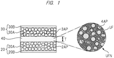
- FIG. 1 is a cross-sectional view schematically showing a configuration of an all-solid-state battery according to an embodiment.
- This all-solid-state battery (also referred to as solid battery) is a lithium ion secondary battery.
- the lithium ion secondary battery according to the present embodiment includes a negative electrode 20, a positive electrode 30, and a solid electrolyte membrane (solid electrolyte layer) 40 arranged therebetween.
- the negative electrode 20 has a negative electrode mixture layer 20A and a negative electrode current collector 20B.
- the negative electrode mixture layer 20A has a negative electrode active material 2AP and a solid electrolyte material (solid electrolyte material for negative electrode). Further, the negative electrode mixture layer 20A may have a negative electrode conductive assistant, a negative electrode binder, and the like.
- the negative electrode current collector 20B is made of, for example, metal foil (for example, copper foil).
- the negative electrode active material 2AP a material capable of occluding and releasing lithium, for example, graphite (natural graphite, artificial graphite, etc.) can be used.
- the negative electrode active material 2AP is granular.
- the positive electrode 30 has a positive electrode mixture layer 30A and a positive electrode current collector 30B.
- the positive electrode mixture layer 30A has a positive electrode active material 3AP and a solid electrolyte material (solid electrolyte material for positive electrode). Further, the positive electrode mixture layer 30A may have a positive electrode conductive assistant, a positive electrode binder, and the like.
- the positive electrode current collector 30B is made of, for example, metal foil (for example, aluminum foil).
- the positive electrode active material 3AP a material capable of occluding and releasing lithium, for example, an oxide containing lithium (LiCoO 2 , LiNiO 2 , LiMnO 2 , etc.) can be used.
- the positive electrode active material 3AP is granular.
- the solid electrolyte membrane 40 is made of a solid electrolyte material.
- a material having Li ion conductivity can be used.
- the solid electrolyte material is granular.
- solid electrolyte material a sulfide-based solid electrolyte or an oxide-based solid electrolyte can be used.
- a sulfide-based solid electrolyte for example, a sulfide containing Li and P can be used.
- an oxide containing Li can be used as the oxide-based solid electrolyte.
- an oxide containing Li can be used as the oxide-based solid electrolyte.
- La 0.51 Li 0.34 TiO 2.94 , Li 1.3 Al 0.3 Ti 1.7 (PO 4 ) 3 , Li 7 La 3 Zr 2 O 12 , Li 2.9 PO 3.3 N 0.46 , Li 3.6 Si 0.6 P 0.4 O 4 , Li 1.5 Al 0.5 Ge 1.5 (PO 4 ) 3 , and the like can be presented.
- solid electrolyte one type may be used alone, or two or more types may be used in combination as needed. Also, the solid electrolytes included in the positive electrode and the negative electrode may be of the same or different types.
- the solid electrolyte membrane 40 includes an ultrafine fiber non-woven fabric UFN and a solid electrolyte material (solid electrolyte particles 4AP).
- the solid electrolyte particles 4AP are incorporated in the ultrafine fiber non-woven fabric UFN used as a support (see the circular portion in FIG. 1 , FIG. 2 , and FIG. 10(a) ).
- the solid electrolyte particles 4AP are embedded in the fine pores of the ultrafine fiber non-woven fabric UFN, or the solid electrolyte particles 4AP are filled in the fine pores of the ultrafine fiber non-woven fabric UFN.
- the ultrafine fiber non-woven fabric UFN can be formed by the laser electrospinning (LES) method as described later.
- the ultrafine fiber non-woven fabric UFN has a configuration in which ultrafine fibers UF are mutually entwined to be laminated. Also, there are fine pores (fine holes, fine through holes) between the ultrafine fibers UF. As described above, the ultrafine fiber non-woven fabric UFN is microporous. By using the ultrafine fibers UF having a small fiber diameter and high uniformity, the pore diameter becomes finer and the variation thereof becomes smaller.
- the characteristics of the solid electrolyte membrane 40 can be improved by using the configuration in which the solid electrolyte material (particles) is incorporated in the ultrafine fiber non-woven fabric UFN used as a support as described above. Specifically, by supporting (fixing) the solid electrolyte material, which is fine particles, with the ultrafine fiber UF, the ratio of the solid electrolyte material in the solid electrolyte membrane 40 can be increased, and the occupied area (exposed area) of the solid electrolyte material on the surface of the membrane can be increased.
- the contact area between the solid electrolyte membrane 40 and the positive and negative electrodes (positive and negative electrode active materials) can be improved, so that the characteristics (output characteristics, charge/discharge characteristics) of the all-solid-state battery can be improved.
- the film thickness of the solid electrolyte membrane 40 can be reduced, the resistance between the positive electrode and the negative electrode can be reduced, and the characteristics (output characteristics, charge/discharge characteristics) of the all-solid-state battery can be improved.
- the solid electrolyte material which is fine particles
- the ultrafine fiber UF the solid electrolyte material
- the solid electrolyte material can be firmly fixed, and the solid electrolyte material can be prevented from falling off or collapsing. Further, it is also possible to increase the strength of the solid electrolyte membrane.
- ultrafine fibers are fabricated by instantaneously and uniformly heating and melting a fibrous raw material (raw material resin) by irradiating a laser beam in a state of applying a high voltage (for example, about 11 to 24 kV) to a nozzle while sending out the fibrous raw material at a constant speed, and then stretching the material by electrostatic force.
- a high voltage for example, about 11 to 24 kV
- the heating time is short and the thermal decomposition can be suppressed as much as possible.
- the material is stretched by electrostatic force, the application concentration is less likely to occur and the stable fiber spinning is possible.
- FIG. 5 is a schematic diagram showing a configuration of a laser electrospinning apparatus.
- the laser electrospinning apparatus includes a nozzle 3 that sends out a raw material resin, a laser irradiation unit 8 that irradiates a tip of the nozzle 3 with a laser (CO 2 laser) 10, and a collector (fiber collecting unit) 6 that stretches the fibers discharged from the nozzle 3 by electrostatic force.
- a high voltage is applied between the collector 6 and the nozzle 3 by a high voltage generation source 5, and the collector 6 is connected to a ground potential 7.
- the laser irradiation unit 8 irradiates the tip of the nozzle 3 with the laser 10 through a slit 9.
- a thread-like resin (raw material resin) 1 as a raw material is supplied to the nozzle 3 through a roller 2.
- the raw material resin 1 extruded from the nozzle 3 is irradiated with the laser 10 in the state of applying a high voltage between the nozzle 3 and the collector 6 by the high voltage generation source 5, the raw material resin 1 is instantaneously and uniformly heated and melted, stretched by electrostatic force to become the ultrafine fiber UF, and collected on the collector 6.
- the non-woven fabric (fiber web) UFN can be obtained by laminating the ultrafine fibers UF while being entwined with each other.
- thermoplastic resin As the raw material resin, a thermoplastic resin can be used.
- a thermoplastic resin which has a softening temperature of 100°C or higher and is insoluble in an organic solvent (for example, xylene) at 20°C can be used.
- the softening temperature is a temperature at which the thermoplastic material starts to soften rapidly, and can be measured by a method based on "Thermoplastic materials - Determination of Vicat softening temperature (VST)" (JIS K 7206).
- the raw material resin include polyolefins such as polyethylene, high-density polyethylene, polypropylene, and polymethylpentene, polyesters such as polyethylene terephthalate (PET) and polybutylene terephthalate (PBT), polyvinylidene fluoride (PVDF), polyamide, and polyphenylene sulfide. It is preferable to use polyethylene, high-density polyethylene, or polypropylene as the raw material resin. In particular, by using high-density polyethylene (HDPE), the ultrafine fiber non-woven fabric having high strength and high heat resistance can be formed.
- HDPE high-density polyethylene
- polypropylene tends to have a slightly slower crystallization rate than polyethylene
- polypropylene can be preferably used as a raw material resin because crystallization is promoted by the function of the nucleating agent of cellulose nanofiber (CeNF) described later.
- cellulose nanofiber is added to the raw material resin.
- CeNF cellulose nanofiber
- the fiber diameter (average fiber diameter) of the ultrafine fiber to which CeNF is added is 10 ⁇ m or less, preferably 5 ⁇ m or less, and more preferably 1 ⁇ m or less.
- the amount of CeNF added to the raw material resin is, for example, 0.1 vol% or more and 10 vol% or less.
- the fiber diameter (average fiber diameter) of the fiber to which CeNF is not added is about a dozen ⁇ m.
- CeNF is fine powdered cellulose.
- Cellulose (Cell-OH) is a carbohydrate represented by (C 6 H 10 O 5 ) n .
- CeNF is made from pulp or the like as a raw material and is obtained by micronizing the cellulose fibers contained in the pulp or the like to a nanometer size.
- the product obtained by hydrolyzing pulp can be used as cellulose nanofiber.
- the portion where the molecular chains of cellulose are densely and regularly present is sometimes referred to as crystalline cellulose.
- the shape of the powdered cellulose fiber constituting the cellulose nanofiber is not limited, and for example, the powdered cellulose fiber having an elongated particle shape or a substantially spherical shape can be used.
- Cellulose nanofiber is lightweight, has high strength, and has heat resistance. Therefore, by adding it to the raw material resin, the strength and heat resistance of the ultrafine fiber and the ultrafine fiber non-woven fabric can be improved.
- Cellulose may be nano-sized by a defibering treatment (micronizing treatment).
- the defibering treatment includes a chemical treatment method and a mechanical treatment method. These methods may be used in combination. By such a defibering treatment (micronizing treatment), the fiber length and the fiber diameter can be reduced.
- the cellulose nanofiber (CeNF) to be added to the raw material resin preferably has a fiber length (L) of 0.5 ⁇ m or more and 10 ⁇ m or less and a fiber diameter (R) of 0.001 ⁇ m or more and 10 ⁇ m or less. Also, it is preferable that the fiber length (L) and the fiber diameter (R) are smaller than at least the ultrafine fiber diameter R.
- the ultrafine fiber to be formed becomes finer and more uniform. It is conceivable that this is because the hydroxyl group (-OH) of cellulose is a polar group, so that the fiber is easily attracted by the electrostatic force of the collector 6 and becomes finer and more uniform, that is, the stretching effect is increased.
- the fiber diameter of the ultrafine fiber obtained by the LES method can be made finer and more uniform. Further, the pore diameter of the ultrafine fiber non-woven fabric obtained by the LES method can be made finer and more uniform.
- cellulose nanofiber (CeNF) has been described as an example, but cellulose nanocrystal and cellulose nanowhisker may be used.
- Cellulose nanofiber, cellulose nanocrystal, and cellulose nanowhisker are referred to as nanocellulose.
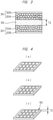
- FIG. 2 is a diagram showing a manufacturing process of a solid electrolyte membrane according to the present embodiment.
- a solid electrolyte membrane is formed using the ultrafine fiber non-woven fabric obtained by the above-described ⁇ Method of fabricating ultrafine fiber non-woven fabric>.
- the ultrafine fiber non-woven fabric UFN shown in FIG. 2 (a) and the slurry S containing the solid electrolyte material are prepared.
- the slurry S is obtained by dispersing a solid electrolyte material in a liquid (solvent, dispersion medium) . If necessary, a binder or the like may be added.
- the slurry S containing the solid electrolyte material is applied onto the ultrafine fiber non-woven fabric UFN.
- FIG. 2(b) the slurry S containing the solid electrolyte material is applied onto the ultrafine fiber non-woven fabric UFN.
- the solid electrolyte membrane 40 in which the solid electrolyte material (solid electrolyte particles 4AP) is incorporated in the fine pores of the ultrafine fiber non-woven fabric UFN in which the ultrafine fibers UF are mutually entwined to be laminated ( FIG. 2(c) ).
- the solid electrolyte membrane 40 can be formed by a simple process and at low cost.
- solid electrolyte material after the liquid component has been removed is denoted by "40A”. Further, the process of removing the liquid component of the slurry S (drying process) and the process of pressurizing the solid electrolyte material (solid electrolyte particles 4AP) may be separately performed.
- FIG. 3 is a cross-sectional view schematically showing a configuration of an all-solid-state battery according to a comparative example.
- FIG. 4 is a diagram showing a manufacturing process of a solid electrolyte sheet of the all-solid-state battery according to the comparative example.
- a solid electrolyte sheet (thickness: 37 to 138 ⁇ m) is fabricated by filling a solid electrolyte into a polyimide sheet-like support ( FIG. 4(a) ) in which a plurality of through holes having a square shape with a side of 200 to 800 ⁇ m processed by a photoetching method is formed ( FIG. 4(b) ), and then heating and pressurizing the support with a press machine ( FIG. 4(c) ).
- each hole has a square shape with a side of 200 to 800 ⁇ m, and there is a limitation in the opening ratio. Namely, when the opening ratio is increased, the contact area between the solid electrolyte and the positive and negative electrodes can be increased, but there is a concern that the solid electrolyte material may fall off or collapse. Further, the thickness of the sheet (T2) is as large as 37 to 138 ⁇ m. On the other hand, in the present embodiment, the film thickness (T) of the solid electrolyte membrane 40 can be easily adjusted, and the film thickness can be set to, for example, 20 ⁇ m or less.
- the characteristics (thickness, fiber diameter, pore diameter, etc.) of the ultrafine fiber non-woven fabric can be easily adjusted by adjusting the processing conditions (applied voltage, distance between the nozzle and the laser irradiation unit, processing time, etc.).
- the volume ratio of the non-woven fabric serving as the support to the solid electrolyte membrane can be suppressed, and can be set to, for example, 10 vol% or more and 30 vol% or less.
- the characteristics of the solid electrolyte membrane can be improved.
- a fiber web (also referred to as non-woven fabric, fiber bundle, or fiber sheet) of HDPE was fabricated by the laser electrospinning (LES) method.
- LES apparatus an electrospinning (ES) apparatus manufactured by Kato Tech Co., Ltd. and a carbon dioxide laser generator (PIN-30R) manufactured by Onizuka Glass Co., Ltd were used in combination.
- ES electrospinning
- PIN-30R carbon dioxide laser generator
- the LES apparatus was covered with an enclosure box made of acrylic resin, and the atmosphere inside the enclosure box was maintained at a humidity of 10 to 30% RH by supplying dry air. In this way, it was possible to eliminate the influence of humidity during fiber formation.
- the wavelength of the CO 2 laser beam was 10.6 ⁇ m, and the laser beam horizontally emitted from the apparatus was reflected by a mirror and the raw material resin directly below the mirror was irradiated with the laser beam.
- the cross-section of the laser beam at the time of emission was circular with a fiber diameter of 6 mm, and it was converted by a beam shape conversion element (expander) so as to have 2.1 mm in a fiber axis direction and 13 mm in a direction horizontal to the fiber axis at the irradiation portion.
- the irradiation diameter of the laser beam was set to about 1.1 mm in the fiber axis direction and about 8.0 mm in the vertical direction by using a slit.
- the diameter of the raw material resin (fibrous) was about 0.5 mm, the distance between the nozzle and the collector was 80 mm, the distance from the nozzle to the central axis of the laser beam was 0.7 mm, and the sending speed was 40 mm/min.
- a roller no rotation, traverse speed: 2 mm/sec was used as a fiber collector (collection plate), and the fiber web of HDPE was fabricated by changing the laser output to 11 to 16 W and changing the applied voltage to 11 to 24 kV.
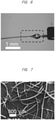
- FIG. 6 is a diagram (photograph) showing a state of a nozzle tip at the time of forming the fiber web of HDPE.
- FIG. 7 is a SEM photograph of the fiber web of HDPE. Morphological observation was performed using SEM (KYENCE, VE-7800) . Prior to the observation, gold evaporation was performed by ion sputter (E-1010 manufactured by Hitachi, Ltd.) so as to enable the SEM observation. In the observation, the distance between two points in the fiber diameter direction was defined as one point for each fiber in the obtained SEM image, and the fiber diameter was obtained by measuring a total of 100 points by using the image analysis software ImageJ. The fiber diameter was a dozen ⁇ m or more.
- a fiber web of CeNF-added HDPE was fabricated by the laser electrospinning (LES) method.
- LES laser electrospinning
- CeNF CeNF-added HDPE
- the amount of CeNF added to HDPE was 1 vol% (CeNF: 1 vol%, HDPE: 99 vol%), and CEOLUS FD101 (manufactured by Asahi Kasei Chemicals Co., Ltd.) was used as CeNF.
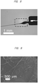
- FIG. 8 is a diagram (photograph) showing a state of a nozzle tip at the time of forming the fiber web of CeNF-added HDPE.
- FIG. 9 is a SEM photograph of the fiber web of CeNF-added HDPE. The fiber diameter of the fiber web of CeNF-added HDPE was 5 ⁇ m or less (about 4 ⁇ m).
- Example 2 As compared with the case of Example 1 in which CeNF was not added, the fiber could be smoothly stretched, the fiber spinning was stable, the fiber diameter was reduced, and the fiber web with uniform thickness was obtained.
- FIG. 10 is a cross-sectional view showing a manufacturing process of an all-solid-state battery.
- the solid electrolyte membrane 40 in which the solid electrolyte particles 4AP are incorporated between the ultrafine fibers UF ( FIG. 10 (a) ) is formed based on the above-mentioned [Method of fabricating solid electrolyte membrane].
- the positive electrode active material 3AP and the solid electrolyte material is mounted on the upper surface side (positive electrode side) of the solid electrolyte membrane 40, the positive electrode current collector 30B is mounted thereon, and then, they are pressurized (pressed). In this way, the positive electrode (positive electrode mixture layer 30A and positive electrode current collector 30B) is formed on the upper surface of the solid electrolyte membrane 40 ( FIG. 10(b) ).
- the negative electrode current collector 20B is mounted thereon, and then, they are pressurized (pressed) .
- the negative electrode negative electrode mixture layer 20A and negative electrode current collector 20B is formed on the lower surface side (negative electrode side) of the solid electrolyte membrane 40 ( FIG. 10(c) ).
- an electrode group composed of the positive electrode current collector 30B, the positive electrode mixture layer 30A, the solid electrolyte membrane 40, the negative electrode mixture layer 20A, and the negative electrode current collector 20B is formed.
- the all-solid-state battery can be formed by inserting the electrode group into the battery case and sealing the battery case.
- the pressurizing process may be performed at once after the positive electrode active material 3AP and the like, the solid electrolyte membrane 40, the negative electrode active material 2AP and the like, and the negative electrode current collector 20B are sequentially stacked on the positive electrode current collector 30B.
- lithium ions are desorbed from the positive electrode active material 3AP of the positive electrode mixture layer 30A during the charging process, and lithium ions desorbed from the negative electrode active material 2AP of the negative electrode mixture layer 20A are inserted during the discharging process. In this way, charging and discharging can be performed by inserting and desorbing lithium ions.
- the solid electrolyte membrane 40 in which the solid electrolyte material (particles) is incorporated in the ultrafine fiber non-woven fabric UFN used as a support, it is possible to manufacture an all-solid-state battery having favorable characteristics. Specifically, as described above, by supporting (fixing) the solid electrolyte material, which is fine particles, with the ultrafine fiber UF, the ratio of the solid electrolyte material in the solid electrolyte membrane 40 can be increased, and the occupied area (exposed area) of the solid electrolyte material on the surface of the membrane can be increased.
- the contact area between the solid electrolyte membrane 40 and the positive and negative electrodes (positive and negative electrode active materials) can be improved, and the characteristics (output characteristics, charge/discharge characteristics) of the all-solid-state battery can be improved.
- the film thickness of the solid electrolyte membrane 40 can be reduced and the resistance between the positive electrode and the negative electrode can be reduced, so that the characteristics (output characteristics, charge/discharge characteristics) of the all-solid-state battery can be improved.
- a secondary battery has been described as an example of a lithium battery, but the present invention can be applied also to a primary battery.
- a lithium battery has been described as an example, but the present invention can be applied also to other all-solid-state batteries.
- CeNF having hydroxyl group (-OH) has been described as an example of a polar filler, but other fillers having a polar group may be used. Both an organic filler and an inorganic filler may be used as the filler.
Landscapes
- Engineering & Computer Science (AREA)
- Chemical & Material Sciences (AREA)
- Chemical Kinetics & Catalysis (AREA)
- General Chemical & Material Sciences (AREA)
- Electrochemistry (AREA)
- Textile Engineering (AREA)
- Manufacturing & Machinery (AREA)
- Inorganic Chemistry (AREA)
- Materials Engineering (AREA)
- Condensed Matter Physics & Semiconductors (AREA)
- General Physics & Mathematics (AREA)
- Physics & Mathematics (AREA)
- Mechanical Engineering (AREA)
- Wood Science & Technology (AREA)
- Life Sciences & Earth Sciences (AREA)
- Composite Materials (AREA)
- Secondary Cells (AREA)
- Spinning Methods And Devices For Manufacturing Artificial Fibers (AREA)
- Nonwoven Fabrics (AREA)
- Conductive Materials (AREA)
- Battery Electrode And Active Subsutance (AREA)
- Multicomponent Fibers (AREA)
Abstract
Description
- The present invention relates to a non-woven fabric, a method of manufacturing a non-woven fabric, a solid electrolyte membrane, a method of manufacturing a solid electrolyte membrane, an all-solid-state battery, and a method of manufacturing an all-solid-state battery.
- Secondary batteries have been developed in the order of lead batteries, nickel-cadmium batteries, nickel metal hydride batteries (Ni-MH batteries), and lithium batteries (LIB) in broad terms. As for the usage thereof, the demand as the power source for mobile phones, notebook computers, and especially electric vehicles (EV) has been rapidly expanding. Among them, LIB is the mainstream of the secondary battery because it has many advantages such as high energy density, high charge/discharge energy, and compact packaging as compared with other secondary batteries . It is known that the LIB has at least three layers of a positive electrode, a separator, and a negative electrode, and is formed to have a structure in which these three layers are covered with an electrolyte. An organic solvent, which is a flammable substance, is generally used as the electrolyte, but recently, an all-solid-state battery has been attracting attention in order to develop a battery with higher safety. In the all-solid-state battery, a flammable organic electrolytic solution is replaced with a non-flammable inorganic solid electrolyte or the like, and its safety is improved as compared with the conventional batteries. Also, in such an all-solid-state battery, further improvement is expected in terms of battery performance, and for example, higher energy density of the battery is expected.
- For example, Patent Document 1 (
Japanese Unexamined Patent Application Publication No. 2010-250982 - Also, Patent Document 2 (
Japanese Unexamined Patent Application Publication No. 2017-103146 - Further, Patent Document 3 (
Japanese Unexamined Patent Application Publication No. 2018-204140 -
- Patent Document 1:
Japanese Unexamined Patent Application Publication No. 2010-250982 - Patent Document 2:
Japanese Unexamined Patent Application Publication No. 2017-103146 - Patent Document 3:
Japanese Unexamined Patent Application Publication No. 2018-204140 - In the all-solid-state battery in
Patent Document 1, for example, the solid electrolyte glass particle powder containing elements such as Li and others is molded to form a sheet, and this sheet is applied to a solid electrolyte. However, since the electrical conduction in the solid electrolyte formed only of the powder material is made by the contact between powders, the contact area becomes small and the output characteristics tend to be inferior to those of the lithium battery using the electrolytic solution. Further, when a powder material is used, it is difficult to form a thin film sheet composed of a layer made of a single material, and the manufacturing process tends to be complicated. - On the other hand, in
Patent Document 2 mentioned above, the solid electrolyte sheet (thickness: 37 to 138 µm) is manufactured by filling a plurality of through holes having a square shape with a side of 200 to 800 µm, which is formed by a photo-etching method in a polyimide sheet-like support (opening ratio: 50 to 99%), with a solid electrolyte, and then performing the heating and pressurizing process with a press machine. However, in this case, since a wet etching method using a chromium-based solvent is used when penetrating the polyimide sheet serving as a support, a harmful organic solvent is used, which poses serious cost and environmental problems. In addition, since the size of the opening is large and the specific gravity of the solid electrolyte is large, the solid electrolyte may gradually fall off from the sheet support in the case of binderless, and the durability tends to be low. Furthermore, since the solid electrolyte layer is thick, the resistance between electrodes becomes high. - From the above, the inventors have reached the knowledge that a high-strength, high-heat-resistant nanofiber non-woven fabric having a small thickness and fine porosity is suitable as a support of a solid electrolyte powder in order to obtain a better solid electrolyte membrane, and have found out the favorable solid electrolyte membrane, method of manufacturing the solid electrolyte membrane, all-solid-state battery, and method of manufacturing the all-solid-state battery as a result of the diligent studies by applying the laser electrospinning (LES) technology (Patent Document 3) developed by the inventors.
- The other problems and novel features will be apparent from the description of this specification and the accompanying drawings.
- An outline of a typical embodiment disclosed in this application will be briefly described as follows.
- A solid electrolyte membrane described in an embodiment disclosed in this application is a solid electrolyte membrane for an all-solid-state battery and includes a non-woven fabric and solid electrolyte particles incorporated in the non-woven fabric, and the non-woven fabric includes a fiber made of a resin containing a polar filler.
- A method of manufacturing a solid electrolyte membrane described in an embodiment disclosed in this application is a method of manufacturing a solid electrolyte membrane for an all-solid-state battery and includes: (a) a step of preparing a non-woven fabric including a fiber made of a resin containing a polar filler; (b) a step of applying a slurry containing solid electrolyte particles onto the non-woven fabric; (c) a step of drying the slurry on the non-woven fabric; and (d) a step of pressurizing the slurry on the non-woven fabric.
- An all-solid-state battery described in an embodiment disclosed in this application is an all-solid-state battery having a positive electrode, a negative electrode, and a solid electrolyte membrane, and the solid electrolyte membrane is arranged between the positive electrode and the negative electrode and includes a non-woven fabric and solid electrolyte particles incorporated in the non-woven fabric, and the non-woven fabric includes a fiber made of a resin containing a polar filler.
- A method of manufacturing an all-solid-state battery described in an embodiment disclosed in this application includes: (a) a step of forming a solid electrolyte membrane; (b) a step of forming a positive electrode mixture layer including a positive electrode active material on a first surface of the solid electrolyte membrane; and (c) a step of forming a negative electrode mixture layer including a negative electrode active material on a second surface of the solid electrolyte membrane. Also, the step (a) includes: (a1) a step of preparing a non-woven fabric including a fiber made of a resin containing a polar filler; (a2) a step of applying a slurry containing solid electrolyte particles onto the non-woven fabric; (a3) a step of drying the slurry on the non-woven fabric; and (a4) a step of pressurizing the slurry on the non-woven fabric.
- According to the non-woven fabric and the method of manufacturing the non-woven fabric described in the typical embodiment disclosed in this application, it is possible to improve the characteristics of the non-woven fabric. Also, according to the solid electrolyte membrane described in the typical embodiment disclosed in this application, it is possible to improve the characteristics of the solid electrolyte membrane. Further, by using the solid electrolyte membrane described in the typical embodiment disclosed in this application, it is possible to improve the characteristics of the all-solid-state battery. Also, according to the method of manufacturing the solid electrolyte membrane described in the typical embodiment disclosed in this application, it is possible to manufacture the solid electrolyte membrane having favorable characteristics. Further, according to the method of manufacturing the all-solid-state battery described in the typical embodiment disclosed in this application, it is possible to manufacture the all-solid-state battery having favorable characteristics.
-
-
FIG. 1 is a cross-sectional view schematically showing a configuration of an all-solid-state battery according to an embodiment; -
FIG. 2 is a diagram showing a manufacturing process of a solid electrolyte membrane according to the embodiment; -
FIG. 3 is a cross-sectional view schematically showing a configuration of an all-solid-state battery according to a comparative example; -
FIG. 4 is a diagram showing a manufacturing process of a solid electrolyte sheet of the all-solid-state battery according to the comparative example; -
FIG. 5 is a schematic diagram showing a configuration of a laser electrospinning apparatus; -
FIG. 6 is a diagram (photograph) showing a state of a nozzle tip at the time of forming a fiber web of HDPE; -
FIG. 7 is a SEM photograph of the fiber web of HDPE; -
FIG. 8 is a diagram (photograph) showing a state of a nozzle tip at the time of forming a fiber web of CeNF-added HDPE; -
FIG. 9 is a SEM photograph of the fiber web of CeNF-added HDPE; and -
FIG. 10 is a cross-sectional view showing a manufacturing process of an all-solid-state battery. - Hereinafter, an embodiment of the present invention will be described in detail with reference to drawings.
-
FIG. 1 is a cross-sectional view schematically showing a configuration of an all-solid-state battery according to an embodiment. This all-solid-state battery (also referred to as solid battery) is a lithium ion secondary battery. - As shown in
FIG. 1 , the lithium ion secondary battery according to the present embodiment includes anegative electrode 20, apositive electrode 30, and a solid electrolyte membrane (solid electrolyte layer) 40 arranged therebetween. - The
negative electrode 20 has a negativeelectrode mixture layer 20A and a negative electrodecurrent collector 20B. The negativeelectrode mixture layer 20A has a negative electrode active material 2AP and a solid electrolyte material (solid electrolyte material for negative electrode). Further, the negativeelectrode mixture layer 20A may have a negative electrode conductive assistant, a negative electrode binder, and the like. The negative electrodecurrent collector 20B is made of, for example, metal foil (for example, copper foil). - As the negative electrode active material 2AP, a material capable of occluding and releasing lithium, for example, graphite (natural graphite, artificial graphite, etc.) can be used. The negative electrode active material 2AP is granular.
- The
positive electrode 30 has a positiveelectrode mixture layer 30A and a positive electrodecurrent collector 30B. The positiveelectrode mixture layer 30A has a positive electrode active material 3AP and a solid electrolyte material (solid electrolyte material for positive electrode). Further, the positiveelectrode mixture layer 30A may have a positive electrode conductive assistant, a positive electrode binder, and the like. The positive electrodecurrent collector 30B is made of, for example, metal foil (for example, aluminum foil). - As the positive electrode active material 3AP, a material capable of occluding and releasing lithium, for example, an oxide containing lithium (LiCoO2, LiNiO2, LiMnO2, etc.) can be used. The positive electrode active material 3AP is granular.
- The
solid electrolyte membrane 40 is made of a solid electrolyte material. As the solid electrolyte material, a material having Li ion conductivity can be used. The solid electrolyte material is granular. - As the solid electrolyte material, a sulfide-based solid electrolyte or an oxide-based solid electrolyte can be used.
- As the sulfide-based solid electrolyte, for example, a sulfide containing Li and P can be used. Specifically, Li2S-SiS2, Li2S-P2S5, Li2S-GeS2, Li2S-B2S3, Li2S-Ga2S3, Li2S-Al2S3, Li2S-GeS2-P2S5, Li2S-Al2S3-P2S5, Li2S-P2S3, Li2S-P2S3-P2S5, LiX-Li2S-P2S5, LiX-Li2S-SiS2, LiX-Li2S-B2S3 (X: I, Br, Cl, or I), and the like can be presented.
- As the oxide-based solid electrolyte, for example, an oxide containing Li can be used. Specifically, La0.51Li0.34TiO2.94, Li1.3Al0.3Ti1.7(PO4)3, Li7La3Zr2O12, Li2.9PO3.3N0.46, Li3.6Si0.6P0.4O4, Li1.5Al0.5Ge1.5(PO4)3, and the like can be presented.
- As the solid electrolyte, one type may be used alone, or two or more types may be used in combination as needed. Also, the solid electrolytes included in the positive electrode and the negative electrode may be of the same or different types.
- Here, in the present embodiment, the
solid electrolyte membrane 40 includes an ultrafine fiber non-woven fabric UFN and a solid electrolyte material (solid electrolyte particles 4AP). Specifically, the solid electrolyte particles 4AP are incorporated in the ultrafine fiber non-woven fabric UFN used as a support (see the circular portion inFIG. 1 ,FIG. 2 , andFIG. 10(a) ). In other words, the solid electrolyte particles 4AP are embedded in the fine pores of the ultrafine fiber non-woven fabric UFN, or the solid electrolyte particles 4AP are filled in the fine pores of the ultrafine fiber non-woven fabric UFN. - The ultrafine fiber non-woven fabric UFN can be formed by the laser electrospinning (LES) method as described later. The ultrafine fiber non-woven fabric UFN has a configuration in which ultrafine fibers UF are mutually entwined to be laminated. Also, there are fine pores (fine holes, fine through holes) between the ultrafine fibers UF. As described above, the ultrafine fiber non-woven fabric UFN is microporous. By using the ultrafine fibers UF having a small fiber diameter and high uniformity, the pore diameter becomes finer and the variation thereof becomes smaller.
- Therefore, the characteristics of the
solid electrolyte membrane 40 can be improved by using the configuration in which the solid electrolyte material (particles) is incorporated in the ultrafine fiber non-woven fabric UFN used as a support as described above. Specifically, by supporting (fixing) the solid electrolyte material, which is fine particles, with the ultrafine fiber UF, the ratio of the solid electrolyte material in thesolid electrolyte membrane 40 can be increased, and the occupied area (exposed area) of the solid electrolyte material on the surface of the membrane can be increased. As a result, the contact area between thesolid electrolyte membrane 40 and the positive and negative electrodes (positive and negative electrode active materials) can be improved, so that the characteristics (output characteristics, charge/discharge characteristics) of the all-solid-state battery can be improved. Also, by supporting (fixing) the solid electrolyte material, which is fine particles, with the ultrafine fiber UF, the film thickness of thesolid electrolyte membrane 40 can be reduced, the resistance between the positive electrode and the negative electrode can be reduced, and the characteristics (output characteristics, charge/discharge characteristics) of the all-solid-state battery can be improved. - In addition, by supporting (fixing) the solid electrolyte material, which is fine particles, with the ultrafine fiber UF, the solid electrolyte material can be firmly fixed, and the solid electrolyte material can be prevented from falling off or collapsing. Further, it is also possible to increase the strength of the solid electrolyte membrane.
- Next, the manufacturing process of the solid electrolyte membrane will be described, and the configuration of the solid electrolyte membrane will be described in more detail.
- In the laser electrospinning (LES) method, ultrafine fibers are fabricated by instantaneously and uniformly heating and melting a fibrous raw material (raw material resin) by irradiating a laser beam in a state of applying a high voltage (for example, about 11 to 24 kV) to a nozzle while sending out the fibrous raw material at a constant speed, and then stretching the material by electrostatic force. As the characteristics of the LES method, since the material is heated by the laser beam, the heating time is short and the thermal decomposition can be suppressed as much as possible. Also, since the material is stretched by electrostatic force, the application concentration is less likely to occur and the stable fiber spinning is possible.
-
FIG. 5 is a schematic diagram showing a configuration of a laser electrospinning apparatus. As shown inFIG. 5 , the laser electrospinning apparatus includes anozzle 3 that sends out a raw material resin, a laser irradiation unit 8 that irradiates a tip of thenozzle 3 with a laser (CO2 laser) 10, and a collector (fiber collecting unit) 6 that stretches the fibers discharged from thenozzle 3 by electrostatic force. A high voltage is applied between thecollector 6 and thenozzle 3 by a high voltage generation source 5, and thecollector 6 is connected to a ground potential 7. The laser irradiation unit 8 irradiates the tip of thenozzle 3 with thelaser 10 through aslit 9. A thread-like resin (raw material resin) 1 as a raw material is supplied to thenozzle 3 through aroller 2. - When the
raw material resin 1 extruded from thenozzle 3 is irradiated with thelaser 10 in the state of applying a high voltage between thenozzle 3 and thecollector 6 by the high voltage generation source 5, theraw material resin 1 is instantaneously and uniformly heated and melted, stretched by electrostatic force to become the ultrafine fiber UF, and collected on thecollector 6. The non-woven fabric (fiber web) UFN can be obtained by laminating the ultrafine fibers UF while being entwined with each other. - As the raw material resin, a thermoplastic resin can be used. For example, a thermoplastic resin which has a softening temperature of 100°C or higher and is insoluble in an organic solvent (for example, xylene) at 20°C can be used. The softening temperature is a temperature at which the thermoplastic material starts to soften rapidly, and can be measured by a method based on "Thermoplastic materials - Determination of Vicat softening temperature (VST)" (JIS K 7206). Specific examples of the raw material resin include polyolefins such as polyethylene, high-density polyethylene, polypropylene, and polymethylpentene, polyesters such as polyethylene terephthalate (PET) and polybutylene terephthalate (PBT), polyvinylidene fluoride (PVDF), polyamide, and polyphenylene sulfide. It is preferable to use polyethylene, high-density polyethylene, or polypropylene as the raw material resin. In particular, by using high-density polyethylene (HDPE), the ultrafine fiber non-woven fabric having high strength and high heat resistance can be formed. Further, although polypropylene tends to have a slightly slower crystallization rate than polyethylene, polypropylene can be preferably used as a raw material resin because crystallization is promoted by the function of the nucleating agent of cellulose nanofiber (CeNF) described later.
- Here, in the present embodiment, cellulose nanofiber (CeNF) is added to the raw material resin. By adding CeNF, the ultrafine fibers become finer and more uniform. It is conceivable that this is because the addition of CeNF to the raw material resin increases the stretching effect by the electrostatic force and promotes the fibers to be ultrafine. The fiber diameter (average fiber diameter) of the ultrafine fiber to which CeNF is added is 10 µm or less, preferably 5 µm or less, and more preferably 1 µm or less. The amount of CeNF added to the raw material resin is, for example, 0.1 vol% or more and 10 vol% or less. On the other hand, the fiber diameter (average fiber diameter) of the fiber to which CeNF is not added is about a dozen µm.
- CeNF is fine powdered cellulose. Cellulose (Cell-OH) is a carbohydrate represented by (C6H10O5)n. CeNF is made from pulp or the like as a raw material and is obtained by micronizing the cellulose fibers contained in the pulp or the like to a nanometer size. For example, the product obtained by hydrolyzing pulp can be used as cellulose nanofiber. The portion where the molecular chains of cellulose are densely and regularly present is sometimes referred to as crystalline cellulose.
- The shape of the powdered cellulose fiber constituting the cellulose nanofiber is not limited, and for example, the powdered cellulose fiber having an elongated particle shape or a substantially spherical shape can be used.
- Cellulose nanofiber is lightweight, has high strength, and has heat resistance. Therefore, by adding it to the raw material resin, the strength and heat resistance of the ultrafine fiber and the ultrafine fiber non-woven fabric can be improved. Cellulose may be nano-sized by a defibering treatment (micronizing treatment). The defibering treatment includes a chemical treatment method and a mechanical treatment method. These methods may be used in combination. By such a defibering treatment (micronizing treatment), the fiber length and the fiber diameter can be reduced.
- The cellulose nanofiber (CeNF) to be added to the raw material resin preferably has a fiber length (L) of 0.5 µm or more and 10 µm or less and a fiber diameter (R) of 0.001 µm or more and 10 µm or less. Also, it is preferable that the fiber length (L) and the fiber diameter (R) are smaller than at least the ultrafine fiber diameter R.
- By adding the cellulose nanofiber (CeNF) described above to the raw material resin, the ultrafine fiber to be formed becomes finer and more uniform. It is conceivable that this is because the hydroxyl group (-OH) of cellulose is a polar group, so that the fiber is easily attracted by the electrostatic force of the
collector 6 and becomes finer and more uniform, that is, the stretching effect is increased. - As described above, by adding a polar filler (filler having a polar group) such as CeNF to the raw material resin, the fiber diameter of the ultrafine fiber obtained by the LES method can be made finer and more uniform. Further, the pore diameter of the ultrafine fiber non-woven fabric obtained by the LES method can be made finer and more uniform.
- In the above description, cellulose nanofiber (CeNF) has been described as an example, but cellulose nanocrystal and cellulose nanowhisker may be used. Cellulose nanofiber, cellulose nanocrystal, and cellulose nanowhisker are referred to as nanocellulose.
-
FIG. 2 is a diagram showing a manufacturing process of a solid electrolyte membrane according to the present embodiment. A solid electrolyte membrane is formed using the ultrafine fiber non-woven fabric obtained by the above-described <Method of fabricating ultrafine fiber non-woven fabric>. - First, the ultrafine fiber non-woven fabric UFN shown in
FIG. 2 (a) and the slurry S containing the solid electrolyte material (solid electrolyte particles 4AP) are prepared. The slurry S is obtained by dispersing a solid electrolyte material in a liquid (solvent, dispersion medium) . If necessary, a binder or the like may be added. Next, as shown inFIG. 2(b) , the slurry S containing the solid electrolyte material is applied onto the ultrafine fiber non-woven fabric UFN. Next, as shown inFIG. 2(c) , by heating the slurry S while pressurizing it, the liquid component of the slurry S is vaporized and the solid electrolyte material (solid electrolyte particles 4AP) is embedded (filled) into the fine pores of the ultrafine fiber non-woven fabric. In this way, it is possible to form thesolid electrolyte membrane 40 in which the solid electrolyte material (solid electrolyte particles 4AP) is incorporated in the fine pores of the ultrafine fiber non-woven fabric UFN in which the ultrafine fibers UF are mutually entwined to be laminated (FIG. 2(c) ). As described above, thesolid electrolyte membrane 40 can be formed by a simple process and at low cost. Note that the solid electrolyte material after the liquid component has been removed is denoted by "40A". Further, the process of removing the liquid component of the slurry S (drying process) and the process of pressurizing the solid electrolyte material (solid electrolyte particles 4AP) may be separately performed. -
FIG. 3 is a cross-sectional view schematically showing a configuration of an all-solid-state battery according to a comparative example. Also,FIG. 4 is a diagram showing a manufacturing process of a solid electrolyte sheet of the all-solid-state battery according to the comparative example. For example, in the comparative example shown inFIG. 3 and FIG. 4 , a solid electrolyte sheet (thickness: 37 to 138 µm) is fabricated by filling a solid electrolyte into a polyimide sheet-like support (FIG. 4(a) ) in which a plurality of through holes having a square shape with a side of 200 to 800 µm processed by a photoetching method is formed (FIG. 4(b) ), and then heating and pressurizing the support with a press machine (FIG. 4(c) ). - In the case of the comparative example described above, each hole has a square shape with a side of 200 to 800 µm, and there is a limitation in the opening ratio. Namely, when the opening ratio is increased, the contact area between the solid electrolyte and the positive and negative electrodes can be increased, but there is a concern that the solid electrolyte material may fall off or collapse. Further, the thickness of the sheet (T2) is as large as 37 to 138 µm. On the other hand, in the present embodiment, the film thickness (T) of the
solid electrolyte membrane 40 can be easily adjusted, and the film thickness can be set to, for example, 20 µm or less. In the LES method, the characteristics (thickness, fiber diameter, pore diameter, etc.) of the ultrafine fiber non-woven fabric can be easily adjusted by adjusting the processing conditions (applied voltage, distance between the nozzle and the laser irradiation unit, processing time, etc.). In particular, the volume ratio of the non-woven fabric serving as the support to the solid electrolyte membrane can be suppressed, and can be set to, for example, 10 vol% or more and 30 vol% or less. - As described above, in the present embodiment, the characteristics of the solid electrolyte membrane can be improved.
- In this example, a fiber web (also referred to as non-woven fabric, fiber bundle, or fiber sheet) of HDPE was fabricated by the laser electrospinning (LES) method. As the LES apparatus, an electrospinning (ES) apparatus manufactured by Kato Tech Co., Ltd. and a carbon dioxide laser generator (PIN-30R) manufactured by Onizuka Glass Co., Ltd were used in combination. As the needle for sending out the fiber, a needle of 20G standard was used, and this was used as the nozzle. The LES apparatus was covered with an enclosure box made of acrylic resin, and the atmosphere inside the enclosure box was maintained at a humidity of 10 to 30% RH by supplying dry air. In this way, it was possible to eliminate the influence of humidity during fiber formation.
- The wavelength of the CO2 laser beam was 10.6 µm, and the laser beam horizontally emitted from the apparatus was reflected by a mirror and the raw material resin directly below the mirror was irradiated with the laser beam. The cross-section of the laser beam at the time of emission was circular with a fiber diameter of 6 mm, and it was converted by a beam shape conversion element (expander) so as to have 2.1 mm in a fiber axis direction and 13 mm in a direction horizontal to the fiber axis at the irradiation portion. Also, the irradiation diameter of the laser beam was set to about 1.1 mm in the fiber axis direction and about 8.0 mm in the vertical direction by using a slit.
- The diameter of the raw material resin (fibrous) was about 0.5 mm, the distance between the nozzle and the collector was 80 mm, the distance from the nozzle to the central axis of the laser beam was 0.7 mm, and the sending speed was 40 mm/min. A roller (no rotation, traverse speed: 2 mm/sec) was used as a fiber collector (collection plate), and the fiber web of HDPE was fabricated by changing the laser output to 11 to 16 W and changing the applied voltage to 11 to 24 kV.
-
FIG. 6 is a diagram (photograph) showing a state of a nozzle tip at the time of forming the fiber web of HDPE.FIG. 7 is a SEM photograph of the fiber web of HDPE. Morphological observation was performed using SEM (KYENCE, VE-7800) . Prior to the observation, gold evaporation was performed by ion sputter (E-1010 manufactured by Hitachi, Ltd.) so as to enable the SEM observation. In the observation, the distance between two points in the fiber diameter direction was defined as one point for each fiber in the obtained SEM image, and the fiber diameter was obtained by measuring a total of 100 points by using the image analysis software ImageJ. The fiber diameter was a dozen µm or more. - In this example, a fiber web of CeNF-added HDPE was fabricated by the laser electrospinning (LES) method. HDPE added with CeNF was used as a raw material resin, and the fiber web was fabricated in the same manner as in Example 1. The amount of CeNF added to HDPE was 1 vol% (CeNF: 1 vol%, HDPE: 99 vol%), and CEOLUS FD101 (manufactured by Asahi Kasei Chemicals Co., Ltd.) was used as CeNF.
-
FIG. 8 is a diagram (photograph) showing a state of a nozzle tip at the time of forming the fiber web of CeNF-added HDPE.FIG. 9 is a SEM photograph of the fiber web of CeNF-added HDPE. The fiber diameter of the fiber web of CeNF-added HDPE was 5 µm or less (about 4 µm). - In this example, as compared with the case of Example 1 in which CeNF was not added, the fiber could be smoothly stretched, the fiber spinning was stable, the fiber diameter was reduced, and the fiber web with uniform thickness was obtained.
- The method of fabricating the all-solid-state battery described with reference to
FIG. 1 is not limited, and for example, the all-solid-state battery can be manufactured as follows.FIG. 10 is a cross-sectional view showing a manufacturing process of an all-solid-state battery. - The
solid electrolyte membrane 40 in which the solid electrolyte particles 4AP are incorporated between the ultrafine fibers UF (FIG. 10 (a) ) is formed based on the above-mentioned [Method of fabricating solid electrolyte membrane]. - Next, a mixture of the positive electrode active material 3AP and the solid electrolyte material is mounted on the upper surface side (positive electrode side) of the
solid electrolyte membrane 40, the positive electrodecurrent collector 30B is mounted thereon, and then, they are pressurized (pressed). In this way, the positive electrode (positiveelectrode mixture layer 30A and positive electrodecurrent collector 30B) is formed on the upper surface of the solid electrolyte membrane 40 (FIG. 10(b) ). - Next, with the lower surface side (negative electrode side) of the
solid electrolyte membrane 40 facing upward, a mixture of the negative electrode active material 2AP and the solid electrolyte material is mounted, the negative electrodecurrent collector 20B is mounted thereon, and then, they are pressurized (pressed) . In this way, the negative electrode (negativeelectrode mixture layer 20A and negative electrodecurrent collector 20B) is formed on the lower surface side (negative electrode side) of the solid electrolyte membrane 40 (FIG. 10(c) ). - Consequently, an electrode group composed of the positive electrode
current collector 30B, the positiveelectrode mixture layer 30A, thesolid electrolyte membrane 40, the negativeelectrode mixture layer 20A, and the negative electrodecurrent collector 20B is formed. - Thereafter, for example, the all-solid-state battery can be formed by inserting the electrode group into the battery case and sealing the battery case.
- Note that the pressurizing process may be performed at once after the positive electrode active material 3AP and the like, the
solid electrolyte membrane 40, the negative electrode active material 2AP and the like, and the negative electrodecurrent collector 20B are sequentially stacked on the positive electrodecurrent collector 30B. - In the above-mentioned all-solid-state battery, lithium ions are desorbed from the positive electrode active material 3AP of the positive
electrode mixture layer 30A during the charging process, and lithium ions desorbed from the negative electrode active material 2AP of the negativeelectrode mixture layer 20A are inserted during the discharging process. In this way, charging and discharging can be performed by inserting and desorbing lithium ions. - As described above, by manufacturing an all-solid-state battery using the
solid electrolyte membrane 40 in which the solid electrolyte material (particles) is incorporated in the ultrafine fiber non-woven fabric UFN used as a support, it is possible to manufacture an all-solid-state battery having favorable characteristics. Specifically, as described above, by supporting (fixing) the solid electrolyte material, which is fine particles, with the ultrafine fiber UF, the ratio of the solid electrolyte material in thesolid electrolyte membrane 40 can be increased, and the occupied area (exposed area) of the solid electrolyte material on the surface of the membrane can be increased. As a result, the contact area between thesolid electrolyte membrane 40 and the positive and negative electrodes (positive and negative electrode active materials) can be improved, and the characteristics (output characteristics, charge/discharge characteristics) of the all-solid-state battery can be improved. Further, by supporting (fixing) the solid electrolyte material, which is fine particles, with the ultrafine fiber UF, the film thickness of thesolid electrolyte membrane 40 can be reduced and the resistance between the positive electrode and the negative electrode can be reduced, so that the characteristics (output characteristics, charge/discharge characteristics) of the all-solid-state battery can be improved. - In the foregoing, the invention made by the inventors of the present invention has been concretely described based on the embodiments and examples. However, it is needless to say that the present invention is not limited to the foregoing embodiments and examples and various modifications can be made within the range not departing from the gist thereof.
- For example, a secondary battery has been described as an example of a lithium battery, but the present invention can be applied also to a primary battery. Also, a lithium battery has been described as an example, but the present invention can be applied also to other all-solid-state batteries. Further, CeNF having hydroxyl group (-OH) has been described as an example of a polar filler, but other fillers having a polar group may be used. Both an organic filler and an inorganic filler may be used as the filler.
-
- 1
- raw material resin
- 2
- roller
- 2AP
- negative electrode active material
- 3
- nozzle
- 3AP
- positive electrode active material
- 4AP
- solid electrolyte particle
- 5
- high voltage generation source
- 6
- collector
- 7
- ground potential
- 8
- laser irradiation unit
- 9
- slit
- 10
- laser
- 20
- negative electrode
- 20A
- negative electrode mixture layer
- 20B
- negative electrode current collector
- 30
- positive electrode
- 30A
- positive electrode mixture layer
- 30B
- positive electrode current collector
- 40
- solid electrolyte membrane
- S
- slurry
- UF
- ultrafine fiber
- UFN
- ultrafine fiber non-woven fabric (non-woven fabric)
Claims (24)
- A non-woven fabric made of fibers,
wherein the fibers are made of a thermoplastic polymer to which nanocellulose is added. - The non-woven fabric according to claim 1,
wherein the amount of the nanocellulose added to the thermoplastic polymer is 0.1 vol% or more and 10 vol% or less. - The non-woven fabric according to claim 1,
wherein the nanocellulose is a cellulose nanofiber, a cellulose nanocrystal, or a cellulose nanowhisker. - The non-woven fabric according to claim 1,
wherein the thermoplastic polymer has a softening temperature of 100°C or higher and is insoluble in an organic solvent. - The non-woven fabric according to claim 1,
wherein the thermoplastic polymer is selected from high-density polyethylene, polypropylene, polymethylpentene, polyethylene terephthalate, polyptylene terephthalate, polyvinylidene fluoride, polyamide, and polyphenylene sulfide. - The non-woven fabric according to claim 1,
wherein an average fiber diameter of the fiber is 5 µm or less. - A method of manufacturing a non-woven fabric,
wherein a thermoplastic polymer to which nanocellulose is added is melted by a laser electrospinning method into a fibrous form, thereby forming the non-woven fabric. - A solid electrolyte membrane including a non-woven fabric serving as a support and a solid electrolyte serving as a matrix component,
wherein the non-woven fabric according to any one of claims 1 to 6 is used as the non-woven fabric. - The solid electrolyte membrane according to claim 8,
wherein the solid electrolyte is lithium ion conductive. - The solid electrolyte membrane according to claim 8,
wherein the solid electrolyte is a sulfide-based solid electrolyte. - The solid electrolyte membrane according to claim 8,
wherein a volume ratio of the support to the solid electrolyte membrane is 10 vol% or more and 30 vol% or less. - An all-solid-state secondary battery including the solid electrolyte membrane according to any one of claims 8 to 11.
- A solid electrolyte membrane for an all-solid-state battery, comprising:a non-woven fabric; andsolid electrolyte particles incorporated in the non-woven fabric,wherein the non-woven fabric includes fibers made of a resin containing a polar filler.
- The solid electrolyte membrane according to claim 13,
wherein the polar filler is cellulose. - The solid electrolyte membrane according to claim 13,
wherein the resin is polyethylene. - A method of manufacturing a solid electrolyte membrane for an all-solid-state battery, comprising:(a) a step of preparing a non-woven fabric including fibers made of a resin containing a polar filler;(b) a step of applying a slurry containing solid electrolyte particles onto the non-woven fabric;(c) a step of drying the slurry on the non-woven fabric; and(d) a step of pressurizing the slurry on the non-woven fabric.
- The method of manufacturing the solid electrolyte membrane according to claim 16,
wherein, in the step (a), the resin containing the polar filler is made to be a fibrous form by a laser electrospinning method, thereby forming the non-woven fabric. - The method of manufacturing the solid electrolyte membrane according to claim 17,
wherein the polar filler is cellulose. - An all-solid-state battery including a positive electrode, a negative electrode, and a solid electrolyte membrane,wherein the solid electrolyte membrane is arranged between the positive electrode and the negative electrode and has a non-woven fabric and solid electrolyte particles incorporated in the non-woven fabric, andwherein the non-woven fabric includes a fiber made of a resin containing a polar filler.
- The all-solid-state battery according to claim 19,
wherein the polar filler is cellulose. - The all-solid-state battery according to claim 19,
wherein the resin is polyethylene. - A method of manufacturing an all-solid-state battery comprising:(a) a step of forming a solid electrolyte membrane;(b) a step of forming a positive electrode mixture layer having a positive electrode active material on a first surface of the solid electrolyte membrane; and(c) a step of forming a negative electrode mixture layer having a negative electrode active material on a second surface of the solid electrolyte membrane,wherein the step (a) includes:(a1) a step of preparing a non-woven fabric including a fiber made of a resin containing a polar filler;(a2) a step of applying a slurry containing solid electrolyte particles onto the non-woven fabric;(a3) a step of drying the slurry on the non-woven fabric; and(a4) a step of pressurizing the slurry on the non-woven fabric.
- The method of manufacturing the all-solid-state battery according to claim 22,
wherein, in the step (a1), the resin containing the polar filler is made to be a fibrous form by a laser electrospinning method, thereby forming the non-woven fabric. - The method of manufacturing the all-solid-state battery according to claim 23,
wherein the polar filler is cellulose.
Applications Claiming Priority (2)
| Application Number | Priority Date | Filing Date | Title |
|---|---|---|---|
| JP2019084028A JP7377401B2 (en) | 2019-04-25 | 2019-04-25 | Non-woven fabric, non-woven fabric manufacturing method, solid electrolyte membrane, solid electrolyte membrane manufacturing method, all-solid-state battery and all-solid-state battery manufacturing method |
| PCT/JP2020/017491 WO2020218417A1 (en) | 2019-04-25 | 2020-04-23 | Non-woven fabric, method for producing non-woven fabric, solid electrolyte membrane, method for producing solid electrolyte membrane, all-solid-battery, and method for producing all-solid-state battery |
Publications (4)
| Publication Number | Publication Date |
|---|---|
| EP3960921A1 true EP3960921A1 (en) | 2022-03-02 |
| EP3960921A4 EP3960921A4 (en) | 2023-01-18 |
| EP3960921B1 EP3960921B1 (en) | 2024-01-31 |
| EP3960921C0 EP3960921C0 (en) | 2024-01-31 |
Family
ID=72942106
Family Applications (1)
| Application Number | Title | Priority Date | Filing Date |
|---|---|---|---|
| EP20794655.9A Active EP3960921B1 (en) | 2019-04-25 | 2020-04-23 | Solid electrolyte membrane, method for producing solid electrolyte membrane, all-solid-battery, and method for producing all-solid-state battery |
Country Status (8)
| Country | Link |
|---|---|
| US (2) | US12506221B2 (en) |
| EP (1) | EP3960921B1 (en) |
| JP (1) | JP7377401B2 (en) |
| KR (1) | KR20220002958A (en) |
| CN (1) | CN114040999A (en) |
| PL (1) | PL3960921T3 (en) |
| TW (2) | TWI871315B (en) |
| WO (1) | WO2020218417A1 (en) |
Families Citing this family (3)
| Publication number | Priority date | Publication date | Assignee | Title |
|---|---|---|---|---|
| JP7635017B2 (en) * | 2021-02-25 | 2025-02-25 | 株式会社東芝 | Method and apparatus for producing a composite electrode |
| JP2023019599A (en) * | 2021-07-29 | 2023-02-09 | 国立大学法人福井大学 | Composite fiber, manufacturing method therefor, and fiber product |
| KR20250081514A (en) * | 2023-11-29 | 2025-06-05 | 삼성에스디아이 주식회사 | All solid-state battery |
Family Cites Families (38)
| Publication number | Priority date | Publication date | Assignee | Title |
|---|---|---|---|---|
| JPH07335217A (en) | 1994-06-07 | 1995-12-22 | Fuji Elelctrochem Co Ltd | Non-aqueous electrolyte secondary battery |
| JPH07335216A (en) | 1994-06-07 | 1995-12-22 | Fuji Elelctrochem Co Ltd | Non-aqueous electrolyte secondary battery |
| JPH07335218A (en) | 1994-06-07 | 1995-12-22 | Fuji Elelctrochem Co Ltd | Non-aqueous electrolyte secondary battery |
| US6288144B1 (en) | 1999-04-20 | 2001-09-11 | Uniroyal Chemical Company, Inc. | Processing of coupled, filled polyolefins |
| JP4876252B2 (en) | 2006-02-28 | 2012-02-15 | 国立大学法人信州大学 | Method for producing extra fine fibers |
| JP5311455B2 (en) | 2008-06-11 | 2013-10-09 | 国立大学法人福井大学 | Spinning method and fiber manufacturing method and apparatus using the same |
| US9861096B2 (en) | 2008-10-01 | 2018-01-09 | Cornell University | Biodegradable chemical delivery system |
| JP5433285B2 (en) | 2009-04-10 | 2014-03-05 | 出光興産株式会社 | Solid electrolyte sheet and lithium secondary battery |
| US8808609B2 (en) * | 2010-01-21 | 2014-08-19 | Tec One Co., Ltd. | Process of making a carbon fiber nonwoven fabric |
| JP5432033B2 (en) | 2010-03-31 | 2014-03-05 | 日本バイリーン株式会社 | Polymer electrolyte membrane |
| ES2369811B1 (en) | 2010-05-04 | 2012-10-15 | Consejo Superior De Investigaciones Científicas (Csic) | PROCEDURE FOR OBTAINING NANOCOMPOSED MATERIALS. |
| JP5462227B2 (en) | 2011-09-07 | 2014-04-02 | 株式会社日本製鋼所 | Process for producing polyolefin microporous stretched film with cellulose nanofiber, polyolefin microporous stretched film with cellulose nanofiber, and separator for non-aqueous secondary battery |
| WO2013084840A1 (en) * | 2011-12-07 | 2013-06-13 | 株式会社カネカ | Nonaqueous electrolyte secondary battery and assembled battery using same |
| JP6088759B2 (en) * | 2012-06-29 | 2017-03-01 | Jxエネルギー株式会社 | Method for producing separator for lithium ion secondary battery |
| US20140121307A1 (en) | 2012-10-30 | 2014-05-01 | Cyclewood Solutions, Inc. | Blending lignin with thermoplastics and a coupling agent or compatibilizer |
| JP2014143006A (en) | 2013-01-22 | 2014-08-07 | Daicel Corp | Composite sheet containing cellulose and solid electrolyte film |
| EP3246970B1 (en) * | 2013-02-05 | 2021-07-07 | Mitsubishi Paper Mills Limited | Non-woven fabric base material for lithium ion secondary battery separator and lithium ion secondary battery separator |
| JP5785574B2 (en) | 2013-02-22 | 2015-09-30 | 出光興産株式会社 | Solid electrolyte sheet for lithium battery, method for producing the same, and all-solid secondary battery using the same |
| JP2014186857A (en) * | 2013-03-22 | 2014-10-02 | Mitsubishi Paper Mills Ltd | Separator base material for lithium ion secondary batteries, and separator for lithium ion secondary batteries |
| JP6496120B2 (en) | 2014-10-20 | 2019-04-03 | 株式会社ダイセル | High melting point resin fiber and nonwoven fabric |
| KR101617964B1 (en) | 2014-11-28 | 2016-05-04 | 한양대학교 산학협력단 | Metal Oxide Fiber, Energy Storage Device Having the Same, and Method for Fabricating the Metal Oxide Fiber |
| JP7127235B2 (en) | 2015-12-03 | 2022-08-31 | 地方独立行政法人大阪産業技術研究所 | Solid electrolyte sheet and manufacturing method thereof, all-solid battery, and manufacturing method of all-solid battery |
| JP6660766B2 (en) | 2016-02-29 | 2020-03-11 | Fdk株式会社 | Manufacturing method of all solid state battery |
| JP2017183111A (en) | 2016-03-30 | 2017-10-05 | 旭化成株式会社 | Separator and method of manufacturing the same |
| WO2017179494A1 (en) | 2016-04-11 | 2017-10-19 | 花王株式会社 | Ultrafine fiber production method |
| CN110234426A (en) * | 2017-01-27 | 2019-09-13 | 沙特基础工业全球技术公司 | Core shell nanocapsule or micro-capsule based on hierarchical zeolite |
| KR102178714B1 (en) | 2017-05-15 | 2020-11-13 | 주식회사 엘지화학 | A method for manufacturing an solid electrolyte sheet for an all solid type battery and an solid electrolyte sheet therefrom |
| JP6928345B2 (en) * | 2017-06-02 | 2021-09-01 | 国立大学法人京都工芸繊維大学 | Fiber sheet manufacturing method |
| US10734673B2 (en) | 2017-06-23 | 2020-08-04 | GM Global Technology Operations LLC | Ionically-conductive reinforced glass ceramic separators/solid electrolytes |
| CN107749491A (en) * | 2017-09-28 | 2018-03-02 | 柔电(武汉)科技有限公司 | flexible all-solid-state battery and preparation method thereof |
| JP6714172B2 (en) * | 2017-09-28 | 2020-06-24 | 富士フイルム株式会社 | Solid electrolyte composition, solid electrolyte-containing sheet and all-solid secondary battery, and method for producing solid electrolyte-containing sheet and all-solid secondary battery |
| KR102598712B1 (en) * | 2018-02-01 | 2023-11-06 | 삼성전자주식회사 | Porous film, Separator comprising porous film, Electrochemical device comprising porous film, and Method for preparing porous film |
| JP6889125B2 (en) | 2018-03-16 | 2021-06-18 | 株式会社東芝 | Separator, electrode group, secondary battery, battery pack, vehicle, and stationary power supply |
| JP6498335B2 (en) | 2018-03-19 | 2019-04-10 | 古河機械金属株式会社 | Solid electrolyte sheet, all solid-state lithium ion battery, and method for producing solid electrolyte sheet |
| WO2019208347A1 (en) | 2018-04-27 | 2019-10-31 | 富士フイルム株式会社 | Solid electrolyte-including sheet, electrode sheet for fully solid-state secondary battery, fully solid-state secondary battery, electronic device, electric vehicle, and manufacturing methods for these |
| CN109244327A (en) * | 2018-09-25 | 2019-01-18 | 合肥先杰新能源科技有限公司 | The preparation method of lithium ion battery composite separation membrane |
| CN109286039A (en) * | 2018-10-22 | 2019-01-29 | 浙江锋锂新能源科技有限公司 | A kind of solid state battery dielectric film and preparation method thereof and the solid state battery with the dielectric film |
| CN109524599A (en) * | 2018-11-24 | 2019-03-26 | 中国科学院青岛生物能源与过程研究所 | High ionic conductivity flexibility sulfide solid electrolyte diaphragm and preparation method thereof |
-
2019
- 2019-04-25 JP JP2019084028A patent/JP7377401B2/en active Active
-
2020
- 2020-04-23 EP EP20794655.9A patent/EP3960921B1/en active Active
- 2020-04-23 US US17/594,611 patent/US12506221B2/en active Active
- 2020-04-23 CN CN202080030573.2A patent/CN114040999A/en active Pending
- 2020-04-23 TW TW109113634A patent/TWI871315B/en active
- 2020-04-23 KR KR1020217036941A patent/KR20220002958A/en not_active Ceased
- 2020-04-23 TW TW113150853A patent/TW202516776A/en unknown
- 2020-04-23 WO PCT/JP2020/017491 patent/WO2020218417A1/en not_active Ceased
- 2020-04-23 PL PL20794655.9T patent/PL3960921T3/en unknown
-
2025
- 2025-11-25 US US19/400,336 patent/US20260081304A1/en active Pending
Also Published As
| Publication number | Publication date |
|---|---|
| EP3960921B1 (en) | 2024-01-31 |
| TWI871315B (en) | 2025-02-01 |
| US20260081304A1 (en) | 2026-03-19 |
| WO2020218417A1 (en) | 2020-10-29 |
| JP7377401B2 (en) | 2023-11-10 |
| US12506221B2 (en) | 2025-12-23 |
| TW202516776A (en) | 2025-04-16 |
| TW202044660A (en) | 2020-12-01 |
| US20220247035A1 (en) | 2022-08-04 |
| KR20220002958A (en) | 2022-01-07 |
| JP2020180393A (en) | 2020-11-05 |
| PL3960921T3 (en) | 2024-04-22 |
| EP3960921C0 (en) | 2024-01-31 |
| CN114040999A (en) | 2022-02-11 |
| EP3960921A4 (en) | 2023-01-18 |
Similar Documents
| Publication | Publication Date | Title |
|---|---|---|
| US20240396092A1 (en) | Method of manufacturing solid electrolyte membrane, method of manufacturing all-solid-state battery, apparatus for manufacturing solid electrolyte membrane, and apparatus for manufacturing all-solid-state battery | |
| Yu et al. | Advances in nonwoven-based separators for lithium-ion batteries | |
| US20260081304A1 (en) | Non-woven fabric, method of manufacturing non-woven fabric, solid electrolyte membrane, method of manufacturing solid electrolyte membrane, all-solid-state battery, and method of manufacturing all-solid-state battery | |
| JP6068444B2 (en) | Separator | |
| CN103493253B (en) | Separator, its manufacturing method and electrochemical device having the same | |
| CN102713039B (en) | Nonwoven fabric made of carbon fiber, carbon fiber, method for producing the same, electrode, battery, and filter | |
| KR20120080596A (en) | Separator for non-aqueous batteries, non-aqueous battery using same, and production method for separator for non-aqueous batteries | |
| CN103562447A (en) | Carbon-fiber material, method for manufacturing carbon-fiber material, and material having carbon-fiber material | |
| CN105322224A (en) | Batteries prepared by spinning | |
| CN104584269A (en) | Composite porous separation membrane having shut-down function, method for manufacturing same, and secondary batteries using same | |
| US9074308B2 (en) | Battery separator comprising a polyolefin nanofilament porous sheet | |
| CN103493258A (en) | Lithium ion cell design apparatus and method | |
| JP2006092829A (en) | Lithium ion secondary battery separator, method for producing the same, and lithium ion secondary battery | |
| CN107820645B (en) | Carbon-silicon composite material, negative electrode and secondary battery | |
| JP6347690B2 (en) | Electrochemical element separator | |
| KR102950244B1 (en) | High-power lithium ion battery composite separator, method for manufacturing the same, and lithium ion secondary battery comprising the same | |
| JP5504457B2 (en) | Lithium ion secondary battery | |
| JP2004172372A (en) | Separator for electric double layer capacitor and electric double layer capacitor | |
| Cihanbeyoğlu | Preparation and characterization of nanofibers for energy applications | |
| Pebenito et al. | c12) Patent Application Publication |
Legal Events
| Date | Code | Title | Description |
|---|---|---|---|
| STAA | Information on the status of an ep patent application or granted ep patent |
Free format text: STATUS: THE INTERNATIONAL PUBLICATION HAS BEEN MADE |
|
| PUAI | Public reference made under article 153(3) epc to a published international application that has entered the european phase |
Free format text: ORIGINAL CODE: 0009012 |
|
| STAA | Information on the status of an ep patent application or granted ep patent |
Free format text: STATUS: REQUEST FOR EXAMINATION WAS MADE |
|
| 17P | Request for examination filed |
Effective date: 20211022 |
|
| AK | Designated contracting states |
Kind code of ref document: A1 Designated state(s): AL AT BE BG CH CY CZ DE DK EE ES FI FR GB GR HR HU IE IS IT LI LT LU LV MC MK MT NL NO PL PT RO RS SE SI SK SM TR |
|
| DAV | Request for validation of the european patent (deleted) | ||
| DAX | Request for extension of the european patent (deleted) | ||
| A4 | Supplementary search report drawn up and despatched |
Effective date: 20221216 |
|
| RIC1 | Information provided on ipc code assigned before grant |
Ipc: H01M 50/454 20210101ALI20221212BHEP Ipc: H01M 50/429 20210101ALI20221212BHEP Ipc: H01M 50/414 20210101ALI20221212BHEP Ipc: H01M 50/44 20210101ALI20221212BHEP Ipc: H01M 10/058 20100101ALI20221212BHEP Ipc: H01M 10/0562 20100101ALI20221212BHEP Ipc: H01M 4/139 20100101ALI20221212BHEP Ipc: H01M 4/13 20100101ALI20221212BHEP Ipc: D01D 5/08 20060101ALI20221212BHEP Ipc: D04H 1/728 20120101ALI20221212BHEP Ipc: D04H 1/42 20120101AFI20221212BHEP |
|
| REG | Reference to a national code |
Ref country code: DE Ref legal event code: R079 Free format text: PREVIOUS MAIN CLASS: D04H0001425000 Ipc: D01D0005080000 Ref country code: DE Ref legal event code: R079 Ref document number: 602020025021 Country of ref document: DE Free format text: PREVIOUS MAIN CLASS: D04H0001425000 Ipc: D01D0005080000 |
|
| GRAP | Despatch of communication of intention to grant a patent |
Free format text: ORIGINAL CODE: EPIDOSNIGR1 |
|
| STAA | Information on the status of an ep patent application or granted ep patent |
Free format text: STATUS: GRANT OF PATENT IS INTENDED |
|
| RIC1 | Information provided on ipc code assigned before grant |
Ipc: H01M 50/454 20210101ALI20230928BHEP Ipc: H01M 50/429 20210101ALI20230928BHEP Ipc: H01M 50/414 20210101ALI20230928BHEP Ipc: H01M 50/44 20210101ALI20230928BHEP Ipc: H01M 10/058 20100101ALI20230928BHEP Ipc: H01M 10/0562 20100101ALI20230928BHEP Ipc: H01M 4/139 20100101ALI20230928BHEP Ipc: H01M 4/13 20100101ALI20230928BHEP Ipc: D01D 5/08 20060101AFI20230928BHEP |
|
| INTG | Intention to grant announced |
Effective date: 20231023 |
|
| GRAS | Grant fee paid |
Free format text: ORIGINAL CODE: EPIDOSNIGR3 |
|
| GRAA | (expected) grant |
Free format text: ORIGINAL CODE: 0009210 |
|
| STAA | Information on the status of an ep patent application or granted ep patent |
Free format text: STATUS: THE PATENT HAS BEEN GRANTED |
|
| AK | Designated contracting states |
Kind code of ref document: B1 Designated state(s): AL AT BE BG CH CY CZ DE DK EE ES FI FR GB GR HR HU IE IS IT LI LT LU LV MC MK MT NL NO PL PT RO RS SE SI SK SM TR |
|
| REG | Reference to a national code |
Ref country code: GB Ref legal event code: FG4D Ref country code: CH Ref legal event code: EP |
|
| REG | Reference to a national code |
Ref country code: DE Ref legal event code: R096 Ref document number: 602020025021 Country of ref document: DE |
|
| REG | Reference to a national code |
Ref country code: IE Ref legal event code: FG4D |
|
| U01 | Request for unitary effect filed |
Effective date: 20240228 |
|
| U07 | Unitary effect registered |
Designated state(s): AT BE BG DE DK EE FI FR IT LT LU LV MT NL PT SE SI Effective date: 20240306 |
|
| U20 | Renewal fee for the european patent with unitary effect paid |
Year of fee payment: 5 Effective date: 20240318 |
|
| PG25 | Lapsed in a contracting state [announced via postgrant information from national office to epo] |
Ref country code: IS Free format text: LAPSE BECAUSE OF FAILURE TO SUBMIT A TRANSLATION OF THE DESCRIPTION OR TO PAY THE FEE WITHIN THE PRESCRIBED TIME-LIMIT Effective date: 20240531 |
|
| PG25 | Lapsed in a contracting state [announced via postgrant information from national office to epo] |
Ref country code: GR Free format text: LAPSE BECAUSE OF FAILURE TO SUBMIT A TRANSLATION OF THE DESCRIPTION OR TO PAY THE FEE WITHIN THE PRESCRIBED TIME-LIMIT Effective date: 20240501 |
|
| PG25 | Lapsed in a contracting state [announced via postgrant information from national office to epo] |
Ref country code: HR Free format text: LAPSE BECAUSE OF FAILURE TO SUBMIT A TRANSLATION OF THE DESCRIPTION OR TO PAY THE FEE WITHIN THE PRESCRIBED TIME-LIMIT Effective date: 20240131 Ref country code: RS Free format text: LAPSE BECAUSE OF FAILURE TO SUBMIT A TRANSLATION OF THE DESCRIPTION OR TO PAY THE FEE WITHIN THE PRESCRIBED TIME-LIMIT Effective date: 20240430 |
|
| PG25 | Lapsed in a contracting state [announced via postgrant information from national office to epo] |
Ref country code: ES Free format text: LAPSE BECAUSE OF FAILURE TO SUBMIT A TRANSLATION OF THE DESCRIPTION OR TO PAY THE FEE WITHIN THE PRESCRIBED TIME-LIMIT Effective date: 20240131 |
|
| PG25 | Lapsed in a contracting state [announced via postgrant information from national office to epo] |
Ref country code: RS Free format text: LAPSE BECAUSE OF FAILURE TO SUBMIT A TRANSLATION OF THE DESCRIPTION OR TO PAY THE FEE WITHIN THE PRESCRIBED TIME-LIMIT Effective date: 20240430 Ref country code: NO Free format text: LAPSE BECAUSE OF FAILURE TO SUBMIT A TRANSLATION OF THE DESCRIPTION OR TO PAY THE FEE WITHIN THE PRESCRIBED TIME-LIMIT Effective date: 20240430 Ref country code: IS Free format text: LAPSE BECAUSE OF FAILURE TO SUBMIT A TRANSLATION OF THE DESCRIPTION OR TO PAY THE FEE WITHIN THE PRESCRIBED TIME-LIMIT Effective date: 20240531 Ref country code: HR Free format text: LAPSE BECAUSE OF FAILURE TO SUBMIT A TRANSLATION OF THE DESCRIPTION OR TO PAY THE FEE WITHIN THE PRESCRIBED TIME-LIMIT Effective date: 20240131 Ref country code: GR Free format text: LAPSE BECAUSE OF FAILURE TO SUBMIT A TRANSLATION OF THE DESCRIPTION OR TO PAY THE FEE WITHIN THE PRESCRIBED TIME-LIMIT Effective date: 20240501 Ref country code: ES Free format text: LAPSE BECAUSE OF FAILURE TO SUBMIT A TRANSLATION OF THE DESCRIPTION OR TO PAY THE FEE WITHIN THE PRESCRIBED TIME-LIMIT Effective date: 20240131 |
|
| PG25 | Lapsed in a contracting state [announced via postgrant information from national office to epo] |
Ref country code: SM Free format text: LAPSE BECAUSE OF FAILURE TO SUBMIT A TRANSLATION OF THE DESCRIPTION OR TO PAY THE FEE WITHIN THE PRESCRIBED TIME-LIMIT Effective date: 20240131 |
|
| PG25 | Lapsed in a contracting state [announced via postgrant information from national office to epo] |
Ref country code: CZ Free format text: LAPSE BECAUSE OF FAILURE TO SUBMIT A TRANSLATION OF THE DESCRIPTION OR TO PAY THE FEE WITHIN THE PRESCRIBED TIME-LIMIT Effective date: 20240131 |
|
| PG25 | Lapsed in a contracting state [announced via postgrant information from national office to epo] |
Ref country code: SK Free format text: LAPSE BECAUSE OF FAILURE TO SUBMIT A TRANSLATION OF THE DESCRIPTION OR TO PAY THE FEE WITHIN THE PRESCRIBED TIME-LIMIT Effective date: 20240131 |
|
| PG25 | Lapsed in a contracting state [announced via postgrant information from national office to epo] |
Ref country code: SM Free format text: LAPSE BECAUSE OF FAILURE TO SUBMIT A TRANSLATION OF THE DESCRIPTION OR TO PAY THE FEE WITHIN THE PRESCRIBED TIME-LIMIT Effective date: 20240131 Ref country code: SK Free format text: LAPSE BECAUSE OF FAILURE TO SUBMIT A TRANSLATION OF THE DESCRIPTION OR TO PAY THE FEE WITHIN THE PRESCRIBED TIME-LIMIT Effective date: 20240131 Ref country code: RO Free format text: LAPSE BECAUSE OF FAILURE TO SUBMIT A TRANSLATION OF THE DESCRIPTION OR TO PAY THE FEE WITHIN THE PRESCRIBED TIME-LIMIT Effective date: 20240131 Ref country code: CZ Free format text: LAPSE BECAUSE OF FAILURE TO SUBMIT A TRANSLATION OF THE DESCRIPTION OR TO PAY THE FEE WITHIN THE PRESCRIBED TIME-LIMIT Effective date: 20240131 |
|
| REG | Reference to a national code |
Ref country code: DE Ref legal event code: R097 Ref document number: 602020025021 Country of ref document: DE |
|
| PG25 | Lapsed in a contracting state [announced via postgrant information from national office to epo] |
Ref country code: MC Free format text: LAPSE BECAUSE OF FAILURE TO SUBMIT A TRANSLATION OF THE DESCRIPTION OR TO PAY THE FEE WITHIN THE PRESCRIBED TIME-LIMIT Effective date: 20240131 |
|
| PG25 | Lapsed in a contracting state [announced via postgrant information from national office to epo] |
Ref country code: MC Free format text: LAPSE BECAUSE OF FAILURE TO SUBMIT A TRANSLATION OF THE DESCRIPTION OR TO PAY THE FEE WITHIN THE PRESCRIBED TIME-LIMIT Effective date: 20240131 |
|
| REG | Reference to a national code |
Ref country code: CH Ref legal event code: PL |
|
| PLBE | No opposition filed within time limit |
Free format text: ORIGINAL CODE: 0009261 |
|
| STAA | Information on the status of an ep patent application or granted ep patent |
Free format text: STATUS: NO OPPOSITION FILED WITHIN TIME LIMIT |
|
| GBPC | Gb: european patent ceased through non-payment of renewal fee |
Effective date: 20240430 |
|
| 26N | No opposition filed |
Effective date: 20241101 |
|
| PG25 | Lapsed in a contracting state [announced via postgrant information from national office to epo] |
Ref country code: GB Free format text: LAPSE BECAUSE OF NON-PAYMENT OF DUE FEES Effective date: 20240430 |
|
| PG25 | Lapsed in a contracting state [announced via postgrant information from national office to epo] |
Ref country code: GB Free format text: LAPSE BECAUSE OF NON-PAYMENT OF DUE FEES Effective date: 20240430 Ref country code: CH Free format text: LAPSE BECAUSE OF NON-PAYMENT OF DUE FEES Effective date: 20240430 |
|
| PG25 | Lapsed in a contracting state [announced via postgrant information from national office to epo] |
Ref country code: IE Free format text: LAPSE BECAUSE OF NON-PAYMENT OF DUE FEES Effective date: 20240423 |
|
| U20 | Renewal fee for the european patent with unitary effect paid |
Year of fee payment: 6 Effective date: 20250326 |
|
| PGFP | Annual fee paid to national office [announced via postgrant information from national office to epo] |
Ref country code: PL Payment date: 20250410 Year of fee payment: 6 |
|
| PG25 | Lapsed in a contracting state [announced via postgrant information from national office to epo] |
Ref country code: CY Free format text: LAPSE BECAUSE OF FAILURE TO SUBMIT A TRANSLATION OF THE DESCRIPTION OR TO PAY THE FEE WITHIN THE PRESCRIBED TIME-LIMIT; INVALID AB INITIO Effective date: 20200423 |
|
| PG25 | Lapsed in a contracting state [announced via postgrant information from national office to epo] |
Ref country code: HU Free format text: LAPSE BECAUSE OF FAILURE TO SUBMIT A TRANSLATION OF THE DESCRIPTION OR TO PAY THE FEE WITHIN THE PRESCRIBED TIME-LIMIT; INVALID AB INITIO Effective date: 20200423 |
|
| U20 | Renewal fee for the european patent with unitary effect paid |
Year of fee payment: 7 Effective date: 20260330 |