EP3960552B1 - Airbag device - Google Patents
Airbag device Download PDFInfo
- Publication number
- EP3960552B1 EP3960552B1 EP20795169.0A EP20795169A EP3960552B1 EP 3960552 B1 EP3960552 B1 EP 3960552B1 EP 20795169 A EP20795169 A EP 20795169A EP 3960552 B1 EP3960552 B1 EP 3960552B1
- Authority
- EP
- European Patent Office
- Prior art keywords
- cushion part
- airbag cushion
- airbag
- vent
- head
- Prior art date
- Legal status (The legal status is an assumption and is not a legal conclusion. Google has not performed a legal analysis and makes no representation as to the accuracy of the status listed.)
- Active
Links
Images


Classifications
-
- B—PERFORMING OPERATIONS; TRANSPORTING
- B60—VEHICLES IN GENERAL
- B60R—VEHICLES, VEHICLE FITTINGS, OR VEHICLE PARTS, NOT OTHERWISE PROVIDED FOR
- B60R21/00—Arrangements or fittings on vehicles for protecting or preventing injuries to occupants or pedestrians in case of accidents or other traffic risks
- B60R21/01—Electrical circuits for triggering passive safety arrangements, e.g. airbags, safety belt tighteners, in case of vehicle accidents or impending vehicle accidents
- B60R21/015—Electrical circuits for triggering passive safety arrangements, e.g. airbags, safety belt tighteners, in case of vehicle accidents or impending vehicle accidents including means for detecting the presence or position of passengers, passenger seats or child seats, and the related safety parameters therefor, e.g. speed or timing of airbag inflation in relation to occupant position or seat belt use
- B60R21/01554—Seat position sensors
-
- B—PERFORMING OPERATIONS; TRANSPORTING
- B60—VEHICLES IN GENERAL
- B60R—VEHICLES, VEHICLE FITTINGS, OR VEHICLE PARTS, NOT OTHERWISE PROVIDED FOR
- B60R21/00—Arrangements or fittings on vehicles for protecting or preventing injuries to occupants or pedestrians in case of accidents or other traffic risks
- B60R21/02—Occupant safety arrangements or fittings, e.g. crash pads
- B60R21/16—Inflatable occupant restraints or confinements designed to inflate upon impact or impending impact, e.g. air bags
- B60R21/20—Arrangements for storing inflatable members in their non-use or deflated condition; Arrangement or mounting of air bag modules or components
- B60R21/207—Arrangements for storing inflatable members in their non-use or deflated condition; Arrangement or mounting of air bag modules or components in vehicle seats
-
- B—PERFORMING OPERATIONS; TRANSPORTING
- B60—VEHICLES IN GENERAL
- B60R—VEHICLES, VEHICLE FITTINGS, OR VEHICLE PARTS, NOT OTHERWISE PROVIDED FOR
- B60R21/00—Arrangements or fittings on vehicles for protecting or preventing injuries to occupants or pedestrians in case of accidents or other traffic risks
- B60R21/02—Occupant safety arrangements or fittings, e.g. crash pads
- B60R21/16—Inflatable occupant restraints or confinements designed to inflate upon impact or impending impact, e.g. air bags
- B60R21/23—Inflatable members
- B60R21/231—Inflatable members characterised by their shape, construction or spatial configuration
- B60R21/23138—Inflatable members characterised by their shape, construction or spatial configuration specially adapted for side protection
-
- B—PERFORMING OPERATIONS; TRANSPORTING
- B60—VEHICLES IN GENERAL
- B60R—VEHICLES, VEHICLE FITTINGS, OR VEHICLE PARTS, NOT OTHERWISE PROVIDED FOR
- B60R21/00—Arrangements or fittings on vehicles for protecting or preventing injuries to occupants or pedestrians in case of accidents or other traffic risks
- B60R21/02—Occupant safety arrangements or fittings, e.g. crash pads
- B60R21/16—Inflatable occupant restraints or confinements designed to inflate upon impact or impending impact, e.g. air bags
- B60R21/23—Inflatable members
- B60R21/231—Inflatable members characterised by their shape, construction or spatial configuration
- B60R21/233—Inflatable members characterised by their shape, construction or spatial configuration comprising a plurality of individual compartments; comprising two or more bag-like members, one within the other
-
- B—PERFORMING OPERATIONS; TRANSPORTING
- B60—VEHICLES IN GENERAL
- B60R—VEHICLES, VEHICLE FITTINGS, OR VEHICLE PARTS, NOT OTHERWISE PROVIDED FOR
- B60R21/00—Arrangements or fittings on vehicles for protecting or preventing injuries to occupants or pedestrians in case of accidents or other traffic risks
- B60R21/02—Occupant safety arrangements or fittings, e.g. crash pads
- B60R21/16—Inflatable occupant restraints or confinements designed to inflate upon impact or impending impact, e.g. air bags
- B60R21/23—Inflatable members
- B60R21/231—Inflatable members characterised by their shape, construction or spatial configuration
- B60R21/2334—Expansion control features
- B60R21/2338—Tethers
-
- B—PERFORMING OPERATIONS; TRANSPORTING
- B60—VEHICLES IN GENERAL
- B60R—VEHICLES, VEHICLE FITTINGS, OR VEHICLE PARTS, NOT OTHERWISE PROVIDED FOR
- B60R21/00—Arrangements or fittings on vehicles for protecting or preventing injuries to occupants or pedestrians in case of accidents or other traffic risks
- B60R21/02—Occupant safety arrangements or fittings, e.g. crash pads
- B60R21/16—Inflatable occupant restraints or confinements designed to inflate upon impact or impending impact, e.g. air bags
- B60R21/23—Inflatable members
- B60R21/239—Inflatable members characterised by their venting means
-
- B—PERFORMING OPERATIONS; TRANSPORTING
- B60—VEHICLES IN GENERAL
- B60R—VEHICLES, VEHICLE FITTINGS, OR VEHICLE PARTS, NOT OTHERWISE PROVIDED FOR
- B60R21/00—Arrangements or fittings on vehicles for protecting or preventing injuries to occupants or pedestrians in case of accidents or other traffic risks
- B60R21/02—Occupant safety arrangements or fittings, e.g. crash pads
- B60R21/16—Inflatable occupant restraints or confinements designed to inflate upon impact or impending impact, e.g. air bags
- B60R21/23—Inflatable members
- B60R21/231—Inflatable members characterised by their shape, construction or spatial configuration
- B60R2021/23107—Inflatable members characterised by their shape, construction or spatial configuration the bag being integrated in a multi-bag system
-
- B—PERFORMING OPERATIONS; TRANSPORTING
- B60—VEHICLES IN GENERAL
- B60R—VEHICLES, VEHICLE FITTINGS, OR VEHICLE PARTS, NOT OTHERWISE PROVIDED FOR
- B60R21/00—Arrangements or fittings on vehicles for protecting or preventing injuries to occupants or pedestrians in case of accidents or other traffic risks
- B60R21/02—Occupant safety arrangements or fittings, e.g. crash pads
- B60R21/16—Inflatable occupant restraints or confinements designed to inflate upon impact or impending impact, e.g. air bags
- B60R21/23—Inflatable members
- B60R21/231—Inflatable members characterised by their shape, construction or spatial configuration
- B60R21/23138—Inflatable members characterised by their shape, construction or spatial configuration specially adapted for side protection
- B60R2021/23146—Inflatable members characterised by their shape, construction or spatial configuration specially adapted for side protection seat mounted
-
- B—PERFORMING OPERATIONS; TRANSPORTING
- B60—VEHICLES IN GENERAL
- B60R—VEHICLES, VEHICLE FITTINGS, OR VEHICLE PARTS, NOT OTHERWISE PROVIDED FOR
- B60R21/00—Arrangements or fittings on vehicles for protecting or preventing injuries to occupants or pedestrians in case of accidents or other traffic risks
- B60R21/02—Occupant safety arrangements or fittings, e.g. crash pads
- B60R21/16—Inflatable occupant restraints or confinements designed to inflate upon impact or impending impact, e.g. air bags
- B60R21/23—Inflatable members
- B60R21/239—Inflatable members characterised by their venting means
- B60R2021/2395—Inflatable members characterised by their venting means comprising means to control the venting
Definitions
- the present invention relates to an airbag device.
- Vehicles are equipped with airbags as safety devices that are activated in the event of a collision or other emergency.
- the driver seat airbag is installed in the center of the steering wheel
- the passenger seat airbag is installed in the instrument panel in the vehicle.
- Patent Document 1 discloses a vehicle seat that can suppress the movement of an occupant in the vehicle width direction by deploying a tension
- Patent Document 2 JP H03 108564 U ) discloses a vehicle seat with cloth provided in the vehicle width direction of the vehicle seat in the event of a collision. airbags on both sides of the seat whereby the venting of the airbags is adapted according to the direction of the impact.
- Patent Document 1 WO 2013-099888
- Patent Document 2 JP H03 108564 U2
- the airbag device of the present invention is defined by claim 1.
- the restraining performance of the occupant can be improved.
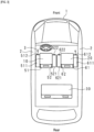
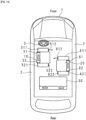
- FIG. 1 is a schematic diagram illustrating an example of a seating arrangement of a vehicle.
- a driver seat 10, a passenger seat 20, and rear seats 30 are arranged as seats in a vehicle 1, and a steering wheel 3 is arranged in front of the driver seat 10. While the so-called left-hand drive is illustrated in FIG. 1 , right-hand drive may also be used.
- the driver seat 10 is provided with a seatback 11, a headrest 12, a storing part 51 for storing an airbag cushion part on one side of the driver seat 10, and a storing part 52 for storing an airbag cushion part on the other side of the driver seat 10.
- the passenger seat 20 is provided with a seatback 21, a headrest 22, a storing part 61 for storing an airbag cushion part on one of the right or left sides of the passenger seat 20, and a storing part 62 for storing an airbag cushion part on the other of the right or left sides of the passenger seat 20.
- the rear seats 30 are provided with seatbacks 31 and headrests 32.
- the driver seat 10, the passenger seat 20, and the rear seats 30 are also referred to herein collectively as seats.
- the positions of the driver seat 10 and the passenger seat 20 (orientation of the seated occupant) in FIG. 1 indicate their normal positions.
- the airbag cushion part on one side of the driver seat 10 in the diagram, the airbag cushion part stored in the storing part 51
- the airbag cushion part on the other side of the driver seat 10 in the lateral direction in the diagram, the airbag cushion part stored in the storing part 52
- the vehicle 1 is capable of driving under autonomous driving control (for example, at a level that does not require operation by the driver), and the driver seat 10 and the passenger seat 20 are installed so that they can rotate 360 degrees.
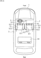
- FIG. 2 is a schematic diagram illustrating an example of the configuration of the airbag device of the present embodiment.
- the airbag device is provided with an electronic control unit (ECU) 100 as a controller, a first airbag cushion part 511 and a second airbag cushion part 521 installed in the driver seat 10, a first active vent 512 provided in the first airbag cushion part 511 and a second active vent 522 provided in the second airbag cushion part 521, and an inflator (gas generating device) 15 provided in each of the first airbag cushion part 511 and the second airbag cushion part 521.
- ECU electronice control unit
- a first airbag cushion part 511 and a second airbag cushion part 521 installed in the driver seat 10
- a first active vent 512 provided in the first airbag cushion part 511 and a second active vent 522 provided in the second airbag cushion part 521
- an inflator (gas generating device) 15 provided in each of the first airbag cushion part 511 and the second airbag cushion part 521.
- the airbag device also includes a first airbag cushion part 611 and a second airbag cushion part 621 installed in the passenger seat 20, a first active vent 612 provided in the first airbag cushion part 611, a second active vent 622 provided in the second airbag cushion part 621, and an inflator (gas generating device) 25 provided in each of the first airbag cushion part 611 and the second airbag cushion part 621.
- a sensor 130 for detecting a collision of the vehicle 1 a driver seat rotational position sensing part 110 for detecting the rotation position of the driver seat 10, and a passenger seat rotational position sensing part 120 for detecting the rotation position of the passenger seat 20 are connected to the ECU 100.
- the first airbag cushion part 511, the second airbag cushion part 521, the first airbag cushion part 611, and the second airbag cushion part 621 are illustrated in dashed lines as expanded and deployed for convenience.
- the ECU 100 controls one of the first active vent 512 and the second active vent 522 to open and the other to close based on the signal output by the driver seat rotational position sensing part 110.
- the ECU 100 controls one of the first active vent 612 and the second active vent 622 to open and the other to close based on the signal output by the passenger seat rotational position sensing part 120.
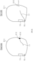
- FIG. 3 is a schematic diagram illustrating an example of the state of the airbag cushion part in the event of a collision in the case of the first arrangement example of the driver seat 10 and passenger seat 20.
- the first arrangement example is a case in which the driver seat 10 and the passenger seat 20 are facing forward, which is a normal condition and in which the occupants seated in the driver seat 10 and the passenger seat 20 are facing forward.
- the active vent is open is illustrated with an arrow that schematically shows the gas being released, while the active vent in the closed state is not marked with an arrow.
- the ECU 100 controls one of the first active vent and the second active vent to open and controls the other to close when the first airbag cushion part and the second airbag cushion part expand and deploy, such as during a vehicle collision.
- an occupant When the active vent in the airbag cushion part is opened, an occupant can be restrained while the pressure in the airbag cushion part is automatically released at the beginning of the expansion and deployment of the airbag cushion part or at the initial stage of the expansion and deployment. This allows the occupant to be restrained while releasing pressure on the airbag cushion part, such as when the occupant is in a position close to the expanding and deploying airbag cushion part (not a normal position).
- the occupant when the active vent provided in the airbag cushion part is closed, the occupant can be restrained while maintaining the pressure in the airbag cushion part during expansion and deployment of the airbag cushion part. This allows the pressure of the airbag cushion part to be maintained to restrain the occupant, such as when the occupant is in a normal position relative to the expanding and deploying airbag cushion part.
- either one of the first airbag cushion part and the second airbag cushion part installed on both sides of the driver seat 10 and the passenger seat 20 of the vehicle 1 can restrain the occupant while automatically releasing the pressure in the airbag cushion part, and the other can restrain the occupant while maintaining the pressure in the airbag cushion part, thereby improving the performance of restraining the occupant.
- the ECU 100 controls the active vents 512 and 612 provided in the airbag cushion parts 511 and 611 of the first airbag cushion part and the second airbag cushion part closer to the body 2 of the vehicle 1 to open according to the rotational positions of the driver seat 10 and the passenger seat 20, and provides control closing the active vents 522 and 622 provided in the airbag cushion parts 521 and 621 of that that is farther from the body 2.
- the airbag cushion parts 511 and 611 closer to the body 2 of the vehicle 1 should restrain the occupant while automatically releasing the pressure in the airbag cushion parts 511 and 611, as the position of the occupant tends to be closer to the airbag cushion parts 511 and 611 during expansion and deployment.
- the airbag cushion parts 521 and 621 farther from the body 2 tend to see the occupant in a normal position relative to the airbag cushion parts 521 and 621 during expansion and deployment, so it is desirable to maintain the pressure in the airbag cushion parts 521 and 621 to restrain the occupant.
- the restraining performance of the occupant can be improved.
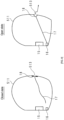
- FIG. 4 is a schematic diagram illustrating an example of the state of the airbag cushion part in the event of a collision in the case of the second arrangement example of the driver seat 10 and passenger seat 20.
- the second arrangement example is a case in which the driver seat 10 and passenger seat 20 are facing rearward, for example, during autonomous driving and the occupants seated in the driver seat 10 and the passenger seat 20 are facing rearward.
- the active vent is open is illustrated with an arrow that schematically shows the gas being released, while the active vent in the closed state is not marked with an arrow.
- both the driver seat 10 and the passenger seat 20 face rearward. However, only one of either the driver seat 10 or passenger seat 20 may be facing rearward.
- the ECU 100 controls the active vents 522 and 622 provided in the airbag cushion parts 521 and 621 of the first airbag cushion part and the second airbag cushion part that is closer to the body 2 of the vehicle 1 to open according to the rotational positions of the driver seat 10 and the passenger seat 20, and provides control closing the active vents 512 and 612 provided in the airbag cushion parts 511 and 611 of that that is farther from the body 2.
- the airbag cushion parts 521 and 621 closer to the body 2 of the vehicle 1 should restrain the occupant while automatically releasing the pressure in the airbag cushion parts 521 and 621, as the position of the occupant tends to be closer to the airbag cushion parts 521 and 621 during expansion and deployment.
- the airbag cushion parts 511 and 611 farther from the body 2 tend to see the occupant in a normal position relative to the airbag cushion parts 511 and 611 during expansion and deployment, so it is desirable to maintain pressure in the airbag cushion parts 511 and 611 to restrain the occupant.
- the restraining performance of the occupant can be improved even if the driver seat 10 or the passenger seat 20 in the vehicle 1 are rotated.
- the driver seat 10 and the passenger seat 20 are installed to be rotatable, but the movement of the seats is not limited to rotational movement, and may also move linearly.
- the ECU 100 can control one of the first active vent and the second active vent to open and the other to close according to the movement positions of the driver seat 10 and the passenger seat 20 that are movable in the vehicle 1.
- Movable includes, for example, rotational movement, linear movement, and the like.
- a change in the movement position of the seat can change the position of the occupant relative to the expanding and deploying airbag cushion part from a normal position (or a more normal position) to a non-normal position (or a less normal position) on one side of the seat width direction (vehicle width direction) to the other.
- the occupant restraining performance can be improved even when the seat is moved in the vehicle.
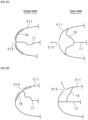
- FIG. 5 is a schematic diagram illustrating a first example of an active vent configuration. Illustrated below is the airbag cushion part 511 in an expanded and deployed state. Although the airbag cushion part 511 will be described, the same applies to the other airbag cushion parts 521, 611, and 621. As illustrated in FIG. 5 , the airbag cushion part 511 is provided with an inflator 15, a tether retaining part 16, a tether 17, and an active vent 512, and a vent 513 is formed in the airbag cushion part 511. In the example of FIG.
- the active vent 512 is folded over the outside of the airbag cushion part 511, a first end of the tether 17 is connected to the tether retaining part 16, and a second end of the tether 17 is connected to the active vent 512 through the vent 513.
- the tether retaining part 16 can comprise, for example, an actuator or the like, and retains or does not retain the tether 17 based on a control signal output by the ECU 100.
- the tether 17 can be formed of a hard and strong material such as, for example, a nylon woven fabric, and is in the form of a string or band.
- the tether retaining part 16 ceases to retain the first end of the tether 17.
- the tether 17 is relaxed and the active vent 512 plugs the vent 513.
- the airbag cushion part 511 expands and deploys in a closed state.
- the tether retaining part 16 retains one end of the tether 17.
- the tether 17 is then pulled.
- the airbag cushion part 511 expands and deploys, for example, at the beginning or initial stages of expansion and deployment, the tether 17 operates to unfold the folded active vent 512, causing a portion of the active vent 512 to separate from the vent 513 and the vent 513 to open.
- the airbag cushion part 511 opens, expanding and deploying.
- FIG. 6 is a schematic diagram illustrating a second example of an active vent configuration.
- the active vent 512 is tacked around the vent 513 of the airbag cushion part 511.
- One end of the tether 17 is connected to the tether retaining part 16 and the other end of the tether 17 is tied to the active vent 512.
- the tether retaining part 16 ceases to retain the first end of the tether 17.
- the tether 17 is relaxed and the active vent 512 plugs the vent 513.
- the airbag cushion part 511 expands and deploys in a closed state.
- the tether retaining part 16 retains one end of the tether 17.
- the tether 17 is then pulled.
- the airbag cushion part 511 expands and deploys, for example, at the initial or early stages of expansion and deployment, the tether 17 operates to unfold the active vent 512, causing a portion of the active vent 512 to separate from the vent 513 and the vent 513 to open.
- the airbag cushion part 511 opens, expanding and deploying.
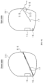
- FIG. 7 is a schematic diagram illustrating a third example of an active vent configuration.
- the active vent 512 is a bundle of base material around the vent of the airbag cushion part 511 and tied down by the tether 17. In this state, the vent is in a closed state.
- the tether retaining part 16 retains the first end of the tether 17.
- the tether 17 is then pulled.
- the tether 17 keeps the base material around the vent tied off, and the airbag cushion part 511 expands and deploys while remaining closed.
- the tether retaining part 16 ceases to retain the first end of the tether 17.
- the tether 17 is then relaxed.
- the pressure within the airbag cushion part 511 operates to undo the tether 17 that binds the base material around the vent, causing the vent to be released.
- the airbag cushion part 511 opens, expanding and deploying.
- FIG. 8 is a schematic diagram illustrating a fourth example of an active vent configuration.
- a patch 18 is provided.
- the patch 18 can be formed, for example, of a base material or other suitable fabric, and the shape of the patch 18 can be rectangular, circular, triangular, or any other shape, as long as the shape allows the vent 513 to open and close.
- the patch 18 is stitched or glued around the vent 513 so as to plug the vent 513.
- the tether retaining part 16 ceases to retain the first end of the tether 17.
- the tether 17 is then relaxed.
- the patch 18 remains sewn or glued around the vent 513 and the airbag cushion part 511 expands and deploys while remaining closed.
- the tether retaining part 16 retains one end of the tether 17.
- the tether 17 is then pulled.
- the patch 18 is pulled by the tether 17, causing some of the portions sewn or glued around the vent 513 to open. As a result, the airbag cushion part 511 opens, expanding and deploying.
- the active vent is provided with a patch 18 that opens or closes a vent 513 in the airbag cushion part 511.
- the patch 18 can be formed, for example, of a base material or other suitable fabric, and the shape can be rectangular, circular, triangular, or other suitable shape, as long as the shape is capable of keeping the vent 513 open or closed.
- the airbag cushion part 511 has the tether 17 that is connected at the first end to the patch 18 and at the second end to the tether retaining part 16.
- the tether 17 can be formed of a hard and strong material such as, for example, a nylon woven fabric, and is in the form of a string or band.
- the tether retaining part 16 can comprise, for example, an actuator or the like, and can retain or cease to retain the second end of the tether 17 based on a control signal output by the ECU 100.
- FIG. 9B shows a fifth example when viewed from the same direction as FIG. 9A .
- the direction in which the tether 17 is pulled is hypothetically the X-axis direction
- the vent 513 is provided at a position displaced in the Y-axis direction from the position of the tether 17.
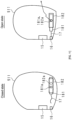
- FIG. 10 is a schematic diagram illustrating a sixth example of an active vent configuration.
- the airbag cushion part 511 is provided with a baffle 515.
- the baffle 515 can be formed, for example, of the necessary base material, and a vent 513 can be formed in the plate-shaped base material, which can be folded to plug the vent 513 and deployed to open the vent 513.
- a vent 513 can be formed in the plate-shaped base material, which can be folded to plug the vent 513 and deployed to open the vent 513.
- the tether retaining part 16 retains the first end of the tether 17.
- the tether 17 is then pulled.
- the baffle 515 will remain tightened by the tether 17 and the vent 513 will remain blocked.
- the airbag cushion part 511 expands and deploys in a closed state.
- the tether retaining part 16 ceases to retain the first end of the tether 17.
- the tether 17 is then relaxed.
- the baffle 515 is deployed, opening the vent 513.
- the airbag cushion part 511 opens, expanding and deploying.
- FIG. 11 is a schematic diagram illustrating a seventh example of an active vent configuration.
- the airbag cushion part 511 has a belt-shaped patch 181 with a vent 181a formed, and a guide 182 with a vent 182a slidably holding the patch 181 inserted inside.
- the vent is open when the position of the vent 181a and the position of the vent 182a overlap in whole or in part, and the vent is closed when the position of the vent 181a and the position of the vent 182a are completely offset (do not overlap at all).
- the tether retaining part 16 ceases to retain the first end of the tether 17.
- the tether 17 is then relaxed.
- the relative positions of the patch 181 and the guide 182 are maintained, and the position of the vent 181a is completely offset from the position of the vent 182a.
- the airbag cushion part 511 expands and deploys in a closed state.
- a head cushion part 517 for protecting the head of an occupant is provided in the airbag cushion part 511.
- the airbag cushion parts 521, 611, and 621 are also provided with a head cushion part.
- the airbag cushion parts 511 and 521 expand and deploy, one of either the head cushion part provided in the airbag cushion part 511 or the head cushion part provided in the airbag cushion part 521 can be expanded and deployed.
- the airbag cushion parts 611 and 621 expand and deploy, one of either the head cushion part provided in the airbag cushion part 611 or the head cushion part provided in the airbag cushion part 621 can be expanded and deployed.
- the other head cushion part is not be expanded and deployed, for example, by remaining stored inside the airbag cushion part.
- the head cushion part installed in either one of the first airbag cushion part and the second airbag cushion part installed on both sides of the seat can restrain the occupant while automatically releasing internal pressure, and the head cushion part installed in the other can restrain the occupant while maintaining pressure, thereby improving the performance of restraining the occupant.
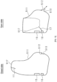
- FIG. 12 is a schematic diagram illustrating a first example of the state of the head cushion part during a collision.
- the airbag cushion part 511 will be explained, but the same applies to other airbag cushion parts 521, 611, and 621.
- the airbag cushion part 511 when the airbag cushion part 511 is controlled to close, the head cushion part 517 provided in the airbag cushion part 511 is expanded and deployed.
- the airbag cushion part 511 is controlled to open, the head cushion part 517 provided in the airbag cushion part 511 is not deployed.
- the head cushion part provided in the airbag cushion part controlled to close is expanded and deployed.
- the airbag cushion part is closed, the position of the occupant is normal (not near) to the airbag cushion part, so the head cushion part is expanded and deployed to protect the head of the occupant. This improves the restraining performance of the occupant.
- all or part of the head cushion part 517 is stored inside the airbag cushion part 511.
- all or part of the head cushion part 517 is folded toward the inside of the airbag cushion part 511.
- the folded portion is also referred to as the tucked-in portion.
- the same is true for the other airbag cushion parts 521, 611, and 621.
- the gas inside the airbag cushion part 511 controlled to close expands and deploys the head cushion part 517 stored inside the airbag cushion part 511.
- the airbag cushion part 511 By controlling the airbag cushion part 511 to close, when the pressure inside the airbag cushion part 511 at the time of expansion and deployment becomes higher than a certain level, the gas inside the airbag cushion part 511 flows into the head cushion part 517, and the head cushion part 517, which is stored inside the airbag cushion part 511, can expand (push out) toward the outside of the airbag cushion part 511, and the head cushion part 517 can be expanded and deployed.
- the tether retaining part 16 retains the tether 17, and the active vent 512 closes the vent 513.
- the tether retaining part 16 ceases to retain the tether 17, and the active vent 512 opens the vent 513.
- the pressure inside the airbag cushion part 511 does not increase during expansion and deployment, and the head cushion part 517 remains stored inside the airbag cushion part 511.
- FIG. 13 is a schematic diagram illustrating a second example of the state of the head cushion part during a collision.
- all or part of the head cushion part 517 is stored inside the airbag cushion part 511.
- all or part of the head cushion part 517 is folded toward the inside of the airbag cushion part 511.
- the first end of the tether 17 is connected to the tether retaining part 16, and the second end of the tether 17 is connected to the required position of the head cushion part 517.
- the head cushion part 517 is expanded and deployed.
- the head cushion part 517 can be expanded and deployed by gas supplied by the inflator 15.
- the head cushion part 517 can be expanded and deployed by the tether retaining part 16 ceasing to retain the tether 17.
- the pressure inside the airbag cushion part 511 does not increases past a prescribed value because the head cushion part 517 expands and deploys, and the active vent 512 keeps the vent 513 closed enabling keeping the airbag cushion part 511 in a closed state.
- the head cushion part 517 remains stored inside the airbag cushion part 511. Specifically, the tether retaining part 16 retains the tether 17, thereby allowing the head cushion part 517 to remain stored within the airbag cushion part 511. In this case, the pressure inside the airbag cushion part 511 increases past a prescribed value because the head cushion part 517 is not deployed, and said pressure causes the active vent 512 to open the vent 513 so that the airbag cushion part 511 can be opened.
- the airbag cushion part 511 and the airbag cushion part 521 can be the same bag shape (same shape) in a non expanded-deployed state.
- the non expanded-deployed state can be a state in which the airbag cushion parts 511 and 521 are assembled (fabricated), for example, unfolded on a flat surface.
- the airbag cushion part 611 and the airbag cushion part 621 can be the same bag shape in a non expanded-deployed state.
- the occupant can be restrained while automatically releasing the pressure in the same manner in both the first airbag cushion part and the second airbag cushion part installed on both sides of the seat, and the occupant can be restrained while maintaining the pressure in the same manner in both the first airbag cushion part and the second airbag cushion part in the same manner.
- each of the airbag cushion parts 511, 521, 611, and 621 can have an active vent opposite an opening portion that supplies gas into the airbag cushion part in an expanded and deployed state.
- the opening portion may be, for example, a gas feed port of the inflator 15 and 25, or, in the case where the airbag is provided with a bulkhead covering the inflator 15 and 25 inside the airbag cushion parts 511, 521, 611, 621, the opening may be a gas feed port provided in the bulkhead.
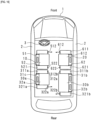
- FIG. 14 is a schematic diagram illustrating an example of the state of the airbag cushion part in the event of a collision in the case of the third arrangement example of the driver seat 10 and passenger seat 20.
- the third arrangement is a case where the driver seat 10 and the passenger seat 20 are facing each other, for example, during autonomous driving, and the occupants seated in the driver seat 10 and the passenger seat 20 are facing each other.
- the relative positions of the driver seat 10 and the passenger seat 20 in the vehicle length direction can be shifted appropriately.
- the open active vent is illustrated with an arrow that schematically shows the gas being released, while the active vent in the closed state is not marked with an arrow.
- the airbag cushion parts 511 and 611 closer to the body 2 or instrument panel of the vehicle 1 should restrain the occupant while automatically releasing the pressure in the airbag cushion parts 511 and 611, because the position of the occupant tends to be closer to the airbag cushion parts 511 and 611 during expansion and deployment.
- the airbag cushion parts 521 and 621 on the far side or interior side of the vehicle from the body 2 should maintain the pressure in the airbag cushion parts 521 and 621 to restrain the occupant, since the occupant tends to be in a normal position relative to the airbag cushion parts 521 and 621 during expansion and deployment.
- the restraining performance of the occupant can be improved even if the driver seat 10 or the passenger seat 20 in the vehicle 1 are rotated.
- FIG. 15 is a schematic diagram illustrating an example of the state of the airbag cushion part in the event of a collision in the case of the fourth arrangement example of the driver seat 10 and passenger seat 20.
- the fourth arrangement is when the driver seat 10 and the passenger seat 20 are facing backward and facing each other, for example, during autonomous driving, and the occupants seated in the driver seat 10 and the passenger seat 20 are facing backward and each other.
- the same control can be performed as in the case of the second arrangement example, so the explanation is omitted.
- FIG. 16 is a schematic diagram illustrating an example of the state of the airbag cushion part in the event of a collision in the case of the fifth arrangement example of the driver seat 10 and passenger seat 20.
- the fifth arrangement shows an example of a case where, in addition to the driver seat 10 and the passenger seat 20, the rear seat 30 can also be separated and moved, for example, during autonomous driving. Since the arrangement example of the driver seat 10 and the passenger seat 20 is the same as the third arrangement example in FIG. 14 , the same control as in the third arrangement example can be performed.
- the rear seat 30 can be separated into a first rear seat 30a and a second rear seat 30b, wherein the first rear seat 30a and the second rear seat 30b are facing each other, and the occupants seated in the first rear seat 30a and the second rear seat 30b are also facing each other.
- the rear seats can be provided with a rear seat rotational position sensing part capable of detecting separation or movement of the rear seats 30.
- the airbag cushion parts 321a, 321b closer to the body 2 on the rear side of the vehicle 1 should restrain the occupant while automatically releasing the pressure in the airbag cushion parts 321a, 321b because the occupant's position tends to be closer to the airbag cushion parts 321a, 321b during expansion and deployment. This is desirable.
- the airbag cushion parts 311a and 311b on the far side or interior side of the vehicle from the body 2 of the rear should maintain the pressure in the airbag cushion parts 311a and 311b to restrain the occupant, since the occupant tends to be in a normal position relative to the airbag cushion parts 311a and 311b during expansion and deployment.
- the restraining performance of the occupant can be improved even if the rear seats 30 are moved inside the vehicle 1.
- the airbag device of the present embodiment includes a first airbag cushion part and a second airbag cushion part installed on each side of a seat of a vehicle, a first active vent provided in the first airbag cushion part and a second active vent provided in the second airbag cushion part, and a controller that controls the first active vent or the second active vent to open and the other to close when the first airbag cushion part and the second airbag cushion part are expanded and deployed.
- a first airbag cushion part and a second airbag cushion part are installed on both sides of a seat of a vehicle, wherein a first active vent is provided in the first airbag cushion part and a second active vent is provided in the second airbag cushion part.
- the controller controls one of the first active vent and the second active vent to open and controls the other to close when the first airbag cushion part and the second airbag cushion part expand and deploy, such as during a vehicle collision.
- the airbag cushion part provided with active vents is expanded and deployed by gas supplied by an inflator (gas generating device) in the event of a vehicle collision.
- an inflator gas generating device
- an occupant can be restrained while the pressure in the airbag cushion part is automatically released at the beginning of the expansion and deployment of the airbag cushion part or at the initial stage of the expansion and deployment. This allows the occupant to be restrained while releasing pressure on the airbag cushion part, such as when the occupant is in a position close to the expanding and deploying airbag cushion part (not a normal position).
- the occupant when the active vent provided in the airbag cushion part is closed, the occupant can be restrained while maintaining the pressure in the airbag cushion part during expansion and deployment of the airbag cushion part. This allows the pressure of the airbag cushion part to be maintained to restrain the occupant, such as when the occupant is in a normal position relative to the expanding and deploying airbag cushion part.
- either one of the first airbag cushion part and the second airbag cushion part installed on both sides of the seat of the vehicle can restrain the occupant while automatically releasing the pressure in the airbag cushion part, and the other can restrain the occupant while maintaining the pressure in the airbag cushion part, thereby improving restraining performance of the occupant.
- the restraining performance of the occupant can be improved even when the seat is moved in the vehicle.
- the restraining performance of the occupant can be improved even when the seat is rotated in the vehicle.
- a first head cushion part for protecting the head of an occupant is provided in the first airbag cushion part and a second head cushion part for protecting the head of an occupant is provided in the second airbag cushion part, such that either one of the first head cushion part or the second head cushion part is expanded and deployed when the first airbag cushion part or the second airbag cushion part is expanded and deployed.
- the first head cushion part for protecting the head of an occupant is provided in the first airbag cushion part
- the second head cushion part is provided in the second airbag cushion part.
- the head cushion part installed in either one of the first airbag cushion part and the second airbag cushion part installed on both sides of the vehicle seat can restrain the occupant while automatically releasing the internal pressure, and the head cushion part installed in the other can restrain the occupant while maintaining the pressure, thereby improving occupant restraining performance.
- the head cushion part of the airbag cushion part controlled to close is expanded and deployed.
- the head cushion part provided in the airbag cushion part controlled to close is expanded and deployed.
- the airbag cushion part is closed, the position of the occupant is normal (not near) to the airbag cushion part, so the head cushion part is expanded and deployed to protect the head of the occupant. This improves the restraining performance of the occupant.
- all or a part of the first head cushion part is stored inside the first airbag cushion part and all or a part of the second head cushion part is stored inside the second airbag cushion part, such that the head cushion part stored inside the airbag cushion part is expanded and deployed by the gas inside the airbag cushion part controlled to be closed.
- All or part of the first head cushion part is stored inside the first airbag cushion part.
- all or part of the first head cushion part is folded toward the inside of the first airbag cushion part.
- the folded portion is also referred to as the tucked-in portion.
- All or part of the second head cushion part is stored inside the second airbag cushion part.
- all or part of the second head cushion part is folded toward the inside of the second airbag cushion part.
- the gas inside the airbag cushion part controlled to close expands and deploys the head cushion part stored inside the airbag cushion part.
- the airbag cushion part controlled to close, when the pressure inside the airbag cushion part at the time of expansion and deployment becomes higher than a certain level, the gas inside the airbag cushion part flows into the head cushion part, and the head cushion part, which is stored inside the airbag cushion part, can expand (push out) toward the outside of the airbag cushion part, and the head cushion part can be expanded and deployed.
- all or part of the first head cushion part is stored inside the first airbag cushion part
- all or part of the second head cushion part is stored inside the second airbag cushion part, such that by expanding and deploying either one of the first head cushion part or the second head cushion part, the expanding and deploying head cushion part closes off the airbag cushion part it was stored in.
- first head cushion part or the second head cushion part is expanded and deployed.
- first head cushion part or the second head cushion part can be expanded and deployed by gas supplied by an inflator (gas generating device).
- an inflator gas generating device.
- the pressure inside the airbag cushion part storing the head cushion part does not increase, and the active vent can remain in a closed state, allowing the airbag cushion part to remain in a closed state.
- the first airbag cushion part and the second airbag cushion part have the same bag shape in a non expanded-deployed state.
- the first airbag cushion part and the second airbag cushion part have the same bag shape in the non expanded-deployed state.
- the occupant can be restrained while automatically releasing the pressure in the same manner in either the first airbag cushion part or the second airbag cushion part installed on both sides of the vehicle seat, and the occupant can be restrained while maintaining the pressure in the same manner in either the first airbag cushion part or the second airbag cushion part.
- the first airbag cushion part and the second airbag cushion part are respectively arranged with the first active vent and the second active vent arranged so as to face the opening portion for supplying gas inside the first airbag cushion part and the second airbag cushion part in the expanded and deployed state.
- the first airbag cushion part and the second airbag cushion part are respectively arranged with the first active vent and the second active vent facing the opening portion for supplying gas inside the first airbag cushion part and the second airbag cushion part in the expanded and deployed.
- the first active vent and the second active vent are respectively provided with a patch that can open or close a vent provided on the first airbag cushion part and the second airbag cushion part
- the first airbag cushion part and the second airbag cushion part each have a tether connected at one end to the patch and connected at the other end to a tether retaining part provided, which either retains or ceases to retain the tether, where the patch either opens or closes the vent by the tether retaining part either retaining or ceasing to retain the tether.
- Each of the first airbag cushion part and the second airbag cushion part is provided with a tether that is connected at a first end to the patch and at a second end to a tether retaining part.
- the tether can be formed of a hard, strong material, such as a nylon weave, for example, and is in the form of a string or band.
- the tether retaining part can be made up of, for example, an actuator or the like, and can retain or cease to retain the second end of the tether based on an external control signal.
- the tether retaining part retains or ceases to retain the tether, which causes the patch to open or close the vent.
- the tether retaining part may retain the tether within the expanding and deploying airbag cushion part, thereby keeping the patch in close contact with the vent and keeping the vent closed, or the patch may be detached from the vent to keep the vent open.
- the tether retaining part may cease to retain the tether, relaxing the tether within the expanding and deploying airbag cushion part, thereby keeping the patch in close contact with the vent and keeping the vent closed, or the patch may be detached from the vent to open the vent. This allows the first airbag cushion part and the second airbag cushion part to be in both an open state and in a closed state.
Landscapes
- Engineering & Computer Science (AREA)
- Mechanical Engineering (AREA)
- Air Bags (AREA)
Description
- The present invention relates to an airbag device.
- Vehicles are equipped with airbags as safety devices that are activated in the event of a collision or other emergency. For example, the driver seat airbag is installed in the center of the steering wheel, and the passenger seat airbag is installed in the instrument panel in the vehicle.
-
Patent Document 1 discloses a vehicle seat that can suppress the movement of an occupant in the vehicle width direction by deploying a tension Patent Document 2 (JP H03 108564 U - [Patent Document 1]:
WO 2013-099888 [Patent Document 2]:JP H03 108564 U2 - In recent years, the development of autonomous driving technologies have been progressing, and it is conceivable that the seats in the vehicle can be moved or rotated during autonomous driving according to the passenger's preference. However, when the position of the seat is changed, the direction of the seated occupant changes, which may result in insufficient restraint of the occupant by the airbag during a collision.
- In light of such circumstances, an object of the present invention is to provide an airbag device capable of improving the restraining performance of an occupant by an airbag during a collision.
- The airbag device of the present invention is defined by
claim 1. - According to the present invention, the restraining performance of the occupant can be improved.
-
-
FIG. 1 is a schematic diagram illustrating an example of a seating arrangement of a vehicle. -
FIG. 2 is a schematic diagram illustrating an example of the configuration of the airbag device of the present embodiment. -
FIG. 3 is a schematic diagram illustrating an example of the state of the airbag cushion part in the event of a collision in the case of the first arrangement example of the driver seat and passenger seat. -
FIG. 4 is a schematic diagram illustrating an example of the state of the airbag cushion part in the event of a collision in the case of the second arrangement example of the driver seat and passenger seat. -
FIG. 5 is a schematic diagram illustrating the first example of an active vent configuration. -
FIG. 6 is a schematic diagram illustrating the second example of an active vent configuration. -
FIG. 7 is a schematic diagram illustrating the third example of an active vent configuration. -
FIG. 8 is a schematic diagram illustrating the fourth example of an active vent configuration. -
FIG. 9A is a schematic diagram illustrating the fifth example of an active vent configuration. -
FIG. 9B is a schematic diagram illustrating the fifth example of an active vent configuration. -
FIG. 10 is a schematic diagram illustrating the sixth example of an active vent configuration. -
FIG. 11 is a schematic diagram illustrating the seventh example of an active vent configuration. -
FIG. 12 is a schematic diagram illustrating the first example of the state of the head cushion part in the event of a collision. -
FIG. 13 is a schematic diagram illustrating the second example of the state of the head cushion part in the event of a collision. -
FIG. 14 is a schematic diagram illustrating an example of the state of the airbag cushion part in the event of a collision in the case of the third arrangement example of the driver seat and passenger seat. -
FIG. 15 is a schematic diagram illustrating an example of the state of the airbag cushion part in the event of a collision in the case of the fourth arrangement example of the driver seat and passenger seat. -
FIG. 16 is a schematic diagram illustrating an example of the state of the airbag cushion part in the event of a collision in the case of the fifth arrangement example of the driver seat and passenger seat. - An embodiment of the present invention is described below based on the drawings.
FIG. 1 is a schematic diagram illustrating an example of a seating arrangement of a vehicle. Adriver seat 10, apassenger seat 20, andrear seats 30 are arranged as seats in avehicle 1, and asteering wheel 3 is arranged in front of thedriver seat 10. While the so-called left-hand drive is illustrated inFIG. 1 , right-hand drive may also be used. Thedriver seat 10 is provided with aseatback 11, aheadrest 12, astoring part 51 for storing an airbag cushion part on one side of thedriver seat 10, and a storingpart 52 for storing an airbag cushion part on the other side of thedriver seat 10. Thepassenger seat 20 is provided with a seatback 21, aheadrest 22, astoring part 61 for storing an airbag cushion part on one of the right or left sides of thepassenger seat 20, and astoring part 62 for storing an airbag cushion part on the other of the right or left sides of thepassenger seat 20. Therear seats 30 are provided withseatbacks 31 andheadrests 32. Thedriver seat 10, thepassenger seat 20, and therear seats 30 are also referred to herein collectively as seats. - The positions of the
driver seat 10 and the passenger seat 20 (orientation of the seated occupant) inFIG. 1 indicate their normal positions. In other words, the airbag cushion part on one side of the driver seat 10 (in the diagram, the airbag cushion part stored in the storing part 51) is located closer to abody 2 of thevehicle 1, and the airbag cushion part on the other side of thedriver seat 10 in the lateral direction (in the diagram, the airbag cushion part stored in the storing part 52) is located far from thebody 2 of thevehicle 1. The same applies to the left and right airbag cushion parts of thepassenger seat 20. Thevehicle 1 is capable of driving under autonomous driving control (for example, at a level that does not require operation by the driver), and thedriver seat 10 and thepassenger seat 20 are installed so that they can rotate 360 degrees. -
FIG. 2 is a schematic diagram illustrating an example of the configuration of the airbag device of the present embodiment. The airbag device is provided with an electronic control unit (ECU) 100 as a controller, a firstairbag cushion part 511 and a secondairbag cushion part 521 installed in thedriver seat 10, a firstactive vent 512 provided in the firstairbag cushion part 511 and a secondactive vent 522 provided in the secondairbag cushion part 521, and an inflator (gas generating device) 15 provided in each of the firstairbag cushion part 511 and the secondairbag cushion part 521. The airbag device also includes a firstairbag cushion part 611 and a secondairbag cushion part 621 installed in thepassenger seat 20, a firstactive vent 612 provided in the firstairbag cushion part 611, a secondactive vent 622 provided in the secondairbag cushion part 621, and an inflator (gas generating device) 25 provided in each of the firstairbag cushion part 611 and the secondairbag cushion part 621. Asensor 130 for detecting a collision of thevehicle 1, a driver seat rotationalposition sensing part 110 for detecting the rotation position of thedriver seat 10, and a passenger seat rotationalposition sensing part 120 for detecting the rotation position of thepassenger seat 20 are connected to theECU 100. InFIG. 2 , the firstairbag cushion part 511, the secondairbag cushion part 521, the firstairbag cushion part 611, and the secondairbag cushion part 621 are illustrated in dashed lines as expanded and deployed for convenience. - In the event of a vehicle collision, the ECU 100 activates the
inflators sensor 130. Theinflator 15 is, for example, filled with compressed gas and supplies gas into the firstairbag cushion part 511 and the secondairbag cushion part 521 based on an activation signal output by theECU 100 to cause the firstairbag cushion part 511 and the secondairbag cushion part 521 to expand and deploy. Similarly, theinflator 25 is filled with compressed gas, for example, and supplies gas into the firstairbag cushion part 611 and the secondairbag cushion part 621 based on an activation signal output by theECU 100 to expand and deploy the firstairbag cushion part 611 and the secondairbag cushion part 621. - The ECU 100 controls one of the first
active vent 512 and the secondactive vent 522 to open and the other to close based on the signal output by the driver seat rotationalposition sensing part 110. The ECU 100 controls one of the firstactive vent 612 and the secondactive vent 622 to open and the other to close based on the signal output by the passenger seat rotationalposition sensing part 120. -
FIG. 3 is a schematic diagram illustrating an example of the state of the airbag cushion part in the event of a collision in the case of the first arrangement example of thedriver seat 10 andpassenger seat 20. The first arrangement example is a case in which thedriver seat 10 and thepassenger seat 20 are facing forward, which is a normal condition and in which the occupants seated in thedriver seat 10 and thepassenger seat 20 are facing forward. In the diagram, the active vent is open is illustrated with an arrow that schematically shows the gas being released, while the active vent in the closed state is not marked with an arrow. - The ECU 100 controls one of the first active vent and the second active vent to open and controls the other to close when the first airbag cushion part and the second airbag cushion part expand and deploy, such as during a vehicle collision.
- When the active vent in the airbag cushion part is opened, an occupant can be restrained while the pressure in the airbag cushion part is automatically released at the beginning of the expansion and deployment of the airbag cushion part or at the initial stage of the expansion and deployment. This allows the occupant to be restrained while releasing pressure on the airbag cushion part, such as when the occupant is in a position close to the expanding and deploying airbag cushion part (not a normal position).
- On the other hand, when the active vent provided in the airbag cushion part is closed, the occupant can be restrained while maintaining the pressure in the airbag cushion part during expansion and deployment of the airbag cushion part. This allows the pressure of the airbag cushion part to be maintained to restrain the occupant, such as when the occupant is in a normal position relative to the expanding and deploying airbag cushion part.
- With the above-described configuration, either one of the first airbag cushion part and the second airbag cushion part installed on both sides of the
driver seat 10 and thepassenger seat 20 of thevehicle 1 can restrain the occupant while automatically releasing the pressure in the airbag cushion part, and the other can restrain the occupant while maintaining the pressure in the airbag cushion part, thereby improving the performance of restraining the occupant. - More specifically, the
ECU 100 controls theactive vents airbag cushion parts body 2 of thevehicle 1 to open according to the rotational positions of thedriver seat 10 and thepassenger seat 20, and provides control closing theactive vents airbag cushion parts body 2. - The
airbag cushion parts body 2 of thevehicle 1 should restrain the occupant while automatically releasing the pressure in theairbag cushion parts airbag cushion parts airbag cushion parts body 2 tend to see the occupant in a normal position relative to theairbag cushion parts airbag cushion parts - Therefore, by controlling the
active vents airbag cushion parts body 2 of thevehicle 1 to open, and controlling theactive vents airbag cushion parts body 2 to close, the restraining performance of the occupant can be improved. -
FIG. 4 is a schematic diagram illustrating an example of the state of the airbag cushion part in the event of a collision in the case of the second arrangement example of thedriver seat 10 andpassenger seat 20. The second arrangement example is a case in which thedriver seat 10 andpassenger seat 20 are facing rearward, for example, during autonomous driving and the occupants seated in thedriver seat 10 and thepassenger seat 20 are facing rearward. In the diagram, the active vent is open is illustrated with an arrow that schematically shows the gas being released, while the active vent in the closed state is not marked with an arrow. In the example ofFIG. 4 , both thedriver seat 10 and thepassenger seat 20 face rearward. However, only one of either thedriver seat 10 orpassenger seat 20 may be facing rearward. - As illustrated in
FIG. 4 , theECU 100 controls theactive vents airbag cushion parts body 2 of thevehicle 1 to open according to the rotational positions of thedriver seat 10 and thepassenger seat 20, and provides control closing theactive vents airbag cushion parts body 2. - The
airbag cushion parts body 2 of thevehicle 1 should restrain the occupant while automatically releasing the pressure in theairbag cushion parts airbag cushion parts airbag cushion parts body 2 tend to see the occupant in a normal position relative to theairbag cushion parts airbag cushion parts - Therefore, by controlling the
active vents airbag cushion parts body 2 of thevehicle 1 to open, and controlling theactive vents airbag cushion parts body 2 to close, the restraining performance of the occupant can be improved even if thedriver seat 10 or thepassenger seat 20 in thevehicle 1 are rotated. - In the example of
FIG. 4 , thedriver seat 10 and thepassenger seat 20 are installed to be rotatable, but the movement of the seats is not limited to rotational movement, and may also move linearly. In other words, theECU 100 can control one of the first active vent and the second active vent to open and the other to close according to the movement positions of thedriver seat 10 and thepassenger seat 20 that are movable in thevehicle 1. Movable includes, for example, rotational movement, linear movement, and the like. A change in the movement position of the seat can change the position of the occupant relative to the expanding and deploying airbag cushion part from a normal position (or a more normal position) to a non-normal position (or a less normal position) on one side of the seat width direction (vehicle width direction) to the other. - Therefore, by controlling either one of the first active vent and the second active vent to open and the other to close according to the movement position of the seat, the occupant restraining performance can be improved even when the seat is moved in the vehicle.
- Next, specific examples of active venting of the airbag cushion part will be explained.
-
FIG. 5 is a schematic diagram illustrating a first example of an active vent configuration. Illustrated below is theairbag cushion part 511 in an expanded and deployed state. Although theairbag cushion part 511 will be described, the same applies to the otherairbag cushion parts FIG. 5 , theairbag cushion part 511 is provided with an inflator 15, atether retaining part 16, atether 17, and anactive vent 512, and avent 513 is formed in theairbag cushion part 511. In the example ofFIG. 5 , theactive vent 512 is folded over the outside of theairbag cushion part 511, a first end of thetether 17 is connected to thetether retaining part 16, and a second end of thetether 17 is connected to theactive vent 512 through thevent 513. Thetether retaining part 16 can comprise, for example, an actuator or the like, and retains or does not retain thetether 17 based on a control signal output by theECU 100. Thetether 17 can be formed of a hard and strong material such as, for example, a nylon woven fabric, and is in the form of a string or band. - When the
ECU 100 outputs a control signal to close the active vent, thetether retaining part 16 ceases to retain the first end of thetether 17. Thetether 17 is relaxed and theactive vent 512 plugs thevent 513. As a result, theairbag cushion part 511 expands and deploys in a closed state. - On the other hand, when the
ECU 100 outputs a control signal to open the active vent, thetether retaining part 16 retains one end of thetether 17. Thetether 17 is then pulled. As theairbag cushion part 511 expands and deploys, for example, at the beginning or initial stages of expansion and deployment, thetether 17 operates to unfold the foldedactive vent 512, causing a portion of theactive vent 512 to separate from thevent 513 and thevent 513 to open. As a result, theairbag cushion part 511 opens, expanding and deploying. -
FIG. 6 is a schematic diagram illustrating a second example of an active vent configuration. In the example ofFIG. 6 , theactive vent 512 is tacked around thevent 513 of theairbag cushion part 511. One end of thetether 17 is connected to thetether retaining part 16 and the other end of thetether 17 is tied to theactive vent 512. - When the
ECU 100 outputs a control signal to close the active vent, thetether retaining part 16 ceases to retain the first end of thetether 17. Thetether 17 is relaxed and theactive vent 512 plugs thevent 513. As a result, theairbag cushion part 511 expands and deploys in a closed state. - On the other hand, when the
ECU 100 outputs a control signal to open the active vent, thetether retaining part 16 retains one end of thetether 17. Thetether 17 is then pulled. As theairbag cushion part 511 expands and deploys, for example, at the initial or early stages of expansion and deployment, thetether 17 operates to unfold theactive vent 512, causing a portion of theactive vent 512 to separate from thevent 513 and thevent 513 to open. As a result, theairbag cushion part 511 opens, expanding and deploying. -
FIG. 7 is a schematic diagram illustrating a third example of an active vent configuration. In the example ofFIG. 7 , theactive vent 512 is a bundle of base material around the vent of theairbag cushion part 511 and tied down by thetether 17. In this state, the vent is in a closed state. - When the
ECU 100 outputs a control signal to close the active vent, thetether retaining part 16 retains the first end of thetether 17. Thetether 17 is then pulled. Thetether 17 keeps the base material around the vent tied off, and theairbag cushion part 511 expands and deploys while remaining closed. - On the other hand, when the
ECU 100 outputs a control signal to open the active vent, thetether retaining part 16 ceases to retain the first end of thetether 17. Thetether 17 is then relaxed. As theairbag cushion part 511 expands and deploys, the pressure within theairbag cushion part 511 operates to undo thetether 17 that binds the base material around the vent, causing the vent to be released. As a result, theairbag cushion part 511 opens, expanding and deploying. -
FIG. 8 is a schematic diagram illustrating a fourth example of an active vent configuration. In the example ofFIG. 8 , apatch 18 is provided. Thepatch 18 can be formed, for example, of a base material or other suitable fabric, and the shape of thepatch 18 can be rectangular, circular, triangular, or any other shape, as long as the shape allows thevent 513 to open and close. Thepatch 18 is stitched or glued around thevent 513 so as to plug thevent 513. - When the
ECU 100 outputs a control signal to close the active vent, thetether retaining part 16 ceases to retain the first end of thetether 17. Thetether 17 is then relaxed. Thepatch 18 remains sewn or glued around thevent 513 and theairbag cushion part 511 expands and deploys while remaining closed. - On the other hand, when the
ECU 100 outputs a control signal to open the active vent, thetether retaining part 16 retains one end of thetether 17. Thetether 17 is then pulled. As theairbag cushion part 511 expands and deploys, thepatch 18 is pulled by thetether 17, causing some of the portions sewn or glued around thevent 513 to open. As a result, theairbag cushion part 511 opens, expanding and deploying. - As described above, the active vent is provided with a
patch 18 that opens or closes avent 513 in theairbag cushion part 511. The same is true for the active vents in each of theairbag cushion parts patch 18 can be formed, for example, of a base material or other suitable fabric, and the shape can be rectangular, circular, triangular, or other suitable shape, as long as the shape is capable of keeping thevent 513 open or closed. - The
airbag cushion part 511 has thetether 17 that is connected at the first end to thepatch 18 and at the second end to thetether retaining part 16. The same applies to theairbag cushion parts tether 17 can be formed of a hard and strong material such as, for example, a nylon woven fabric, and is in the form of a string or band. Thetether retaining part 16 can comprise, for example, an actuator or the like, and can retain or cease to retain the second end of thetether 17 based on a control signal output by theECU 100. - The
tether retaining part 16 retains or ceases to retain thetether 17, which allows thepatch 18 to open or close thevent 513. For example, in retaining thetether 17, thetether retaining part 16 may retain thetether 17 in a taut state within the expanding and deployingairbag cushion part 511, thereby releasing thepatch 18 from thevent 513 and causing thevent 513 to open, as illustrated inFIG. 8 , or thepatch 18 may be adhered to the vent 513 (not shown) to close thevent 513. Furthermore, thetether retaining part 16 can cease to retain thetether 17, thereby relaxing thetether 17 in the expanding and deployingairbag cushion part 511, as illustrated inFIG. 8 , and thepatch 18 may be adhered to thevent 513 to close thevent 513, and thepatch 18 may be detached from the vent 513 (not shown) to open thevent 513. This enables individually and independently opening or closing each of theairbag cushion parts ECU 100. -
FIG. 9A and FIG. 9B are schematic diagrams illustrating a fifth example of an active vent configuration.FIG. 9A illustrates a schematic diagram of the fourth example ofFIG. 8 , described above, from a different angle. As illustrated inFIG. 9A , when theairbag cushion part 511 is closed, thetether 17 is relaxed and thepatch 18 is sewn or adhered around thevent 513 with thevent 513 plugged. On the other hand, when theairbag cushion part 511 is open, thetether 17 become pulled and thepatches 18 are pulled by thetether 17, dislodging some of the portions sewn or glued around thevent 513, leaving thevent 513 open. -
FIG. 9B shows a fifth example when viewed from the same direction asFIG. 9A . InFIG. 9B , if the direction in which thetether 17 is pulled is hypothetically the X-axis direction, instead of the configuration (FIG. 9A ) in which the position of thevent 513 is at or near the X-axis, thevent 513 is provided at a position displaced in the Y-axis direction from the position of thetether 17. By using the configuration ofFIG. 9B , when theairbag cushion part 511 expands and deploys and thetether 17 is pulled, a portion of thepatch 18 does not immediately disengage from thevent 513, and thevent 513 remains plugged for a short period, thus allowing a faster speed of theairbag cushion part 511 expanding and deploying in the Y-direction. -
FIG. 10 is a schematic diagram illustrating a sixth example of an active vent configuration. In the example ofFIG. 10 , theairbag cushion part 511 is provided with abaffle 515. Thebaffle 515 can be formed, for example, of the necessary base material, and avent 513 can be formed in the plate-shaped base material, which can be folded to plug thevent 513 and deployed to open thevent 513. By tightening thebaffle 515 using thetether 17, thebaffle 515 can be folded, and by loosening thetether 17, thebaffle 515 can be made deployable and thevent 513 can be opened. - When the
ECU 100 outputs a control signal to close the active vent, thetether retaining part 16 retains the first end of thetether 17. Thetether 17 is then pulled. Thebaffle 515 will remain tightened by thetether 17 and thevent 513 will remain blocked. Theairbag cushion part 511 expands and deploys in a closed state. - On the other hand, when the
ECU 100 outputs a control signal to open the active vent, thetether retaining part 16 ceases to retain the first end of thetether 17. Thetether 17 is then relaxed. Thebaffle 515 is deployed, opening thevent 513. As a result, theairbag cushion part 511 opens, expanding and deploying. -
FIG. 11 is a schematic diagram illustrating a seventh example of an active vent configuration. In the example ofFIG. 11 , theairbag cushion part 511 has a belt-shapedpatch 181 with avent 181a formed, and aguide 182 with a vent 182a slidably holding thepatch 181 inserted inside. As the relative positions of thepatch 181 and theguide 182 change, the vent is open when the position of thevent 181a and the position of the vent 182a overlap in whole or in part, and the vent is closed when the position of thevent 181a and the position of the vent 182a are completely offset (do not overlap at all). - When the
ECU 100 outputs a control signal to close the active vent, thetether retaining part 16 ceases to retain the first end of thetether 17. Thetether 17 is then relaxed. The relative positions of thepatch 181 and theguide 182 are maintained, and the position of thevent 181a is completely offset from the position of the vent 182a. Theairbag cushion part 511 expands and deploys in a closed state. - On the other hand, when the
ECU 100 outputs a control signal to open the active vent, thetether retaining part 16 retains one end of thetether 17. Thetether 17 is then pulled. As theairbag cushion part 511 expands and deploys, the relative positions of thepatch 181 and theguide 182 change, and the position of thevent 181a and the position of the vent 182a overlap in whole or in part, opening the vent. As a result, theairbag cushion part 511 opens, expanding and deploying. - Next, the head cushion part for occupant head protection is described.
- A
head cushion part 517 for protecting the head of an occupant is provided in theairbag cushion part 511. Similarly, theairbag cushion parts airbag cushion parts airbag cushion part 511 or the head cushion part provided in theairbag cushion part 521 can be expanded and deployed. Similarly, when theairbag cushion parts airbag cushion part 611 or the head cushion part provided in theairbag cushion part 621 can be expanded and deployed. The other head cushion part is not be expanded and deployed, for example, by remaining stored inside the airbag cushion part. - With the configuration described above, the head cushion part installed in either one of the first airbag cushion part and the second airbag cushion part installed on both sides of the seat can restrain the occupant while automatically releasing internal pressure, and the head cushion part installed in the other can restrain the occupant while maintaining pressure, thereby improving the performance of restraining the occupant.
-
FIG. 12 is a schematic diagram illustrating a first example of the state of the head cushion part during a collision. In the following, theairbag cushion part 511 will be explained, but the same applies to otherairbag cushion parts FIG. 12 , when theairbag cushion part 511 is controlled to close, thehead cushion part 517 provided in theairbag cushion part 511 is expanded and deployed. When theairbag cushion part 511 is controlled to open, thehead cushion part 517 provided in theairbag cushion part 511 is not deployed. In other words, when either the first airbag cushion part or the second airbag cushion part is controlled to close, the head cushion part provided in the airbag cushion part controlled to close is expanded and deployed. When the airbag cushion part is closed, the position of the occupant is normal (not near) to the airbag cushion part, so the head cushion part is expanded and deployed to protect the head of the occupant. This improves the restraining performance of the occupant. - More specifically, all or part of the
head cushion part 517 is stored inside theairbag cushion part 511. For example, all or part of thehead cushion part 517 is folded toward the inside of theairbag cushion part 511. The folded portion is also referred to as the tucked-in portion. The same is true for the otherairbag cushion parts - As illustrated in
FIG. 12 , the gas inside theairbag cushion part 511 controlled to close expands and deploys thehead cushion part 517 stored inside theairbag cushion part 511. By controlling theairbag cushion part 511 to close, when the pressure inside theairbag cushion part 511 at the time of expansion and deployment becomes higher than a certain level, the gas inside theairbag cushion part 511 flows into thehead cushion part 517, and thehead cushion part 517, which is stored inside theairbag cushion part 511, can expand (push out) toward the outside of theairbag cushion part 511, and thehead cushion part 517 can be expanded and deployed. In this case, thetether retaining part 16 retains thetether 17, and theactive vent 512 closes thevent 513. - The
tether retaining part 16 ceases to retain thetether 17, and theactive vent 512 opens thevent 513. By controlling theairbag cushion part 511 to open, the pressure inside theairbag cushion part 511 does not increase during expansion and deployment, and thehead cushion part 517 remains stored inside theairbag cushion part 511. -
FIG. 13 is a schematic diagram illustrating a second example of the state of the head cushion part during a collision. In the second example, as in the first example, all or part of thehead cushion part 517 is stored inside theairbag cushion part 511. For example, all or part of thehead cushion part 517 is folded toward the inside of theairbag cushion part 511. In the second example, the first end of thetether 17 is connected to thetether retaining part 16, and the second end of thetether 17 is connected to the required position of thehead cushion part 517. - In the closed state illustrated in
FIG. 13 , thehead cushion part 517 is expanded and deployed. For example, thehead cushion part 517 can be expanded and deployed by gas supplied by theinflator 15. Specifically, thehead cushion part 517 can be expanded and deployed by thetether retaining part 16 ceasing to retain thetether 17. In this case, the pressure inside theairbag cushion part 511 does not increases past a prescribed value because thehead cushion part 517 expands and deploys, and theactive vent 512 keeps thevent 513 closed enabling keeping theairbag cushion part 511 in a closed state. - In the open state illustrated in
FIG. 13 , thehead cushion part 517 remains stored inside theairbag cushion part 511. Specifically, thetether retaining part 16 retains thetether 17, thereby allowing thehead cushion part 517 to remain stored within theairbag cushion part 511. In this case, the pressure inside theairbag cushion part 511 increases past a prescribed value because thehead cushion part 517 is not deployed, and said pressure causes theactive vent 512 to open thevent 513 so that theairbag cushion part 511 can be opened. - In the above-described embodiment, the
airbag cushion part 511 and theairbag cushion part 521 can be the same bag shape (same shape) in a non expanded-deployed state. The non expanded-deployed state can be a state in which theairbag cushion parts airbag cushion part 611 and theairbag cushion part 621 can be the same bag shape in a non expanded-deployed state. - As a result, the occupant can be restrained while automatically releasing the pressure in the same manner in both the first airbag cushion part and the second airbag cushion part installed on both sides of the seat, and the occupant can be restrained while maintaining the pressure in the same manner in both the first airbag cushion part and the second airbag cushion part in the same manner.
- In the embodiments described above, each of the
airbag cushion parts inflator airbag cushion parts - This suppresses the gas supplied from the opening portion from being immediately released from the active vent when the airbag cushion part is expanded and deployed by supplying gas from the opening portion into the airbag cushion part at the time of a collision or the like, so that the airbag cushion part can be expanded and deployed in a required state (for example, in the required shape or the required internal pressure).
- Next, the arrangement of the seats in the
vehicle 1 will be described. -
FIG. 14 is a schematic diagram illustrating an example of the state of the airbag cushion part in the event of a collision in the case of the third arrangement example of thedriver seat 10 andpassenger seat 20. The third arrangement is a case where thedriver seat 10 and thepassenger seat 20 are facing each other, for example, during autonomous driving, and the occupants seated in thedriver seat 10 and thepassenger seat 20 are facing each other. The relative positions of thedriver seat 10 and thepassenger seat 20 in the vehicle length direction can be shifted appropriately. In the diagram, the open active vent is illustrated with an arrow that schematically shows the gas being released, while the active vent in the closed state is not marked with an arrow. - The
airbag cushion parts body 2 or instrument panel of thevehicle 1 should restrain the occupant while automatically releasing the pressure in theairbag cushion parts airbag cushion parts airbag cushion parts body 2 should maintain the pressure in theairbag cushion parts airbag cushion parts - Therefore, by controlling the
active vents airbag cushion parts body 2 or the instrument panel of thevehicle 1 to open, and controlling theactive vents airbag cushion parts body 2 or on the interior side of the vehicle to close, the restraining performance of the occupant can be improved even if thedriver seat 10 or thepassenger seat 20 in thevehicle 1 are rotated. -
FIG. 15 is a schematic diagram illustrating an example of the state of the airbag cushion part in the event of a collision in the case of the fourth arrangement example of thedriver seat 10 andpassenger seat 20. The fourth arrangement is when thedriver seat 10 and thepassenger seat 20 are facing backward and facing each other, for example, during autonomous driving, and the occupants seated in thedriver seat 10 and thepassenger seat 20 are facing backward and each other. In the case of the fourth arrangement example, the same control can be performed as in the case of the second arrangement example, so the explanation is omitted. -
FIG. 16 is a schematic diagram illustrating an example of the state of the airbag cushion part in the event of a collision in the case of the fifth arrangement example of thedriver seat 10 andpassenger seat 20. The fifth arrangement shows an example of a case where, in addition to thedriver seat 10 and thepassenger seat 20, therear seat 30 can also be separated and moved, for example, during autonomous driving. Since the arrangement example of thedriver seat 10 and thepassenger seat 20 is the same as the third arrangement example inFIG. 14 , the same control as in the third arrangement example can be performed. - As illustrated in
FIG. 16 , therear seat 30 can be separated into a first rear seat 30a and a secondrear seat 30b, wherein the first rear seat 30a and the secondrear seat 30b are facing each other, and the occupants seated in the first rear seat 30a and the secondrear seat 30b are also facing each other. In this case, as in the case of thedriver seat 10 and thepassenger seat 20, the rear seats can be provided with a rear seat rotational position sensing part capable of detecting separation or movement of therear seats 30. - The
airbag cushion parts body 2 on the rear side of thevehicle 1 should restrain the occupant while automatically releasing the pressure in theairbag cushion parts airbag cushion parts airbag cushion parts body 2 of the rear should maintain the pressure in theairbag cushion parts airbag cushion parts - Therefore, by controlling the
active vents airbag cushion parts body 2 of thevehicle 1 to open, and controlling theactive vents airbag cushion parts body 2, the restraining performance of the occupant can be improved even if therear seats 30 are moved inside thevehicle 1. - The airbag device of the present embodiment includes a first airbag cushion part and a second airbag cushion part installed on each side of a seat of a vehicle, a first active vent provided in the first airbag cushion part and a second active vent provided in the second airbag cushion part, and a controller that controls the first active vent or the second active vent to open and the other to close when the first airbag cushion part and the second airbag cushion part are expanded and deployed.
- A first airbag cushion part and a second airbag cushion part are installed on both sides of a seat of a vehicle, wherein a first active vent is provided in the first airbag cushion part and a second active vent is provided in the second airbag cushion part. The controller controls one of the first active vent and the second active vent to open and controls the other to close when the first airbag cushion part and the second airbag cushion part expand and deploy, such as during a vehicle collision.
- The airbag cushion part provided with active vents is expanded and deployed by gas supplied by an inflator (gas generating device) in the event of a vehicle collision. When the active vent in the airbag cushion part is opened, an occupant can be restrained while the pressure in the airbag cushion part is automatically released at the beginning of the expansion and deployment of the airbag cushion part or at the initial stage of the expansion and deployment. This allows the occupant to be restrained while releasing pressure on the airbag cushion part, such as when the occupant is in a position close to the expanding and deploying airbag cushion part (not a normal position).
- On the other hand, when the active vent provided in the airbag cushion part is closed, the occupant can be restrained while maintaining the pressure in the airbag cushion part during expansion and deployment of the airbag cushion part. This allows the pressure of the airbag cushion part to be maintained to restrain the occupant, such as when the occupant is in a normal position relative to the expanding and deploying airbag cushion part.
- With the configuration described above, either one of the first airbag cushion part and the second airbag cushion part installed on both sides of the seat of the vehicle can restrain the occupant while automatically releasing the pressure in the airbag cushion part, and the other can restrain the occupant while maintaining the pressure in the airbag cushion part, thereby improving restraining performance of the occupant.
- Regarding the airbag device according to the present embodiment, the controller can control one of the first active vent and the second active vent to be open and the other to be closed according to the movement positions of the seats that are movable in the vehicle.
- The controller can control one of the first active vent and the second active vent to open and the other to close according to the movement positions of the seat that are movable in the vehicle. Movable includes, for example, rotational movement, linear movement, and the like. A change in the movement position of the seat can change the position of the occupant relative to the expanding and deploying airbag cushion part from a normal position (or a more normal position) to a non-normal position (or a less normal position) on one side of the seat width direction (vehicle width direction) to the other.
- Therefore, by controlling one of the first active vent and the second active vent to open and the other to close according to the movement position of the seat, the restraining performance of the occupant can be improved even when the seat is moved in the vehicle.
- Regarding the airbag device according the present embodiment, the controller controls the active vent provided in the airbag cushion part among the first airbag cushion part and the second airbag cushion part closer to the body of the vehicle to open according to the rotational position of the seat, and controls the active vent provided in the airbag cushion part farther from the body to close.
- The controller controls the active vent provided in the airbag cushion part among the first airbag cushion part and the second airbag cushion part closer to the body of the vehicle to open according to the rotational position of the seat, and controls the active vent provided in the airbag cushion part farther from the body to close.
- The rotational position of the seat includes, for example, a normal position in which the occupant is facing forward of the vehicle and a reversed position in which the occupant is facing rearward of the vehicle. Regardless of the rotational position of the seat, the airbag cushion part closer to the body of the vehicle should restrain the occupant while automatically releasing the pressure in the airbag cushion part, since the occupant tends to be positioned closer to the airbag cushion part during expansion and deployment. The airbag cushion part farther from the body should maintain the pressure in the airbag cushion part to restrain the occupant, as the occupant tends to be in a normal position relative to the airbag cushion part during expansion and deployment.
- Therefore, by controlling the active vent provided in the airbag cushion part closer to the body of the vehicle to open and controlling the active vent provided in the airbag cushion part farther from the body to close, the restraining performance of the occupant can be improved even when the seat is rotated in the vehicle.
- Regarding the airbag device according to the present invention, a first head cushion part for protecting the head of an occupant is provided in the first airbag cushion part and a second head cushion part for protecting the head of an occupant is provided in the second airbag cushion part, such that either one of the first head cushion part or the second head cushion part is expanded and deployed when the first airbag cushion part or the second airbag cushion part is expanded and deployed.
- The first head cushion part for protecting the head of an occupant is provided in the first airbag cushion part, and the second head cushion part is provided in the second airbag cushion part. When the first airbag cushion part and the second airbag cushion part expand and deploy, either the first head cushion part or the second head cushion part is expanded and deployed. The other head cushion part is not be expanded and deployed, for example, by remaining stored inside the airbag cushion part.
- With the configuration described above, the head cushion part installed in either one of the first airbag cushion part and the second airbag cushion part installed on both sides of the vehicle seat can restrain the occupant while automatically releasing the internal pressure, and the head cushion part installed in the other can restrain the occupant while maintaining the pressure, thereby improving occupant restraining performance.
- Regarding the airbag device according to the present embodiment, when either one of the first airbag cushion part or the second airbag cushion part is controlled to close, the head cushion part of the airbag cushion part controlled to close is expanded and deployed.
- When either the first airbag cushion part or the second airbag cushion part is controlled to close, the head cushion part provided in the airbag cushion part controlled to close is expanded and deployed. When the airbag cushion part is closed, the position of the occupant is normal (not near) to the airbag cushion part, so the head cushion part is expanded and deployed to protect the head of the occupant. This improves the restraining performance of the occupant.
- Regarding the airbag device according to the present embodiment, all or a part of the first head cushion part is stored inside the first airbag cushion part and all or a part of the second head cushion part is stored inside the second airbag cushion part, such that the head cushion part stored inside the airbag cushion part is expanded and deployed by the gas inside the airbag cushion part controlled to be closed.
- All or part of the first head cushion part is stored inside the first airbag cushion part. For example, all or part of the first head cushion part is folded toward the inside of the first airbag cushion part. The folded portion is also referred to as the tucked-in portion. All or part of the second head cushion part is stored inside the second airbag cushion part. For example, all or part of the second head cushion part is folded toward the inside of the second airbag cushion part.
- The gas inside the airbag cushion part controlled to close expands and deploys the head cushion part stored inside the airbag cushion part. By controlling the airbag cushion part to close, when the pressure inside the airbag cushion part at the time of expansion and deployment becomes higher than a certain level, the gas inside the airbag cushion part flows into the head cushion part, and the head cushion part, which is stored inside the airbag cushion part, can expand (push out) toward the outside of the airbag cushion part, and the head cushion part can be expanded and deployed.
- Regarding the airbag device according to the present embodiment, all or part of the first head cushion part is stored inside the first airbag cushion part, and all or part of the second head cushion part is stored inside the second airbag cushion part, such that by expanding and deploying either one of the first head cushion part or the second head cushion part, the expanding and deploying head cushion part closes off the airbag cushion part it was stored in.
- All or part of the first head cushion part is stored inside the first airbag cushion part. For example, all or part of the first head cushion part is folded toward the inside of the first airbag cushion part. The folded portion is also referred to as the tucked-in portion. All or part of the second head cushion part is stored inside the second airbag cushion part. For example, all or part of the second head cushion part is folded toward the inside of the second airbag cushion part.
- Either the first head cushion part or the second head cushion part is expanded and deployed. For example, either the first head cushion part or the second head cushion part can be expanded and deployed by gas supplied by an inflator (gas generating device). As the head cushion part expands and deploys, the pressure inside the airbag cushion part storing the head cushion part does not increase, and the active vent can remain in a closed state, allowing the airbag cushion part to remain in a closed state.
- In the airbag device of the present embodiment, the first airbag cushion part and the second airbag cushion part have the same bag shape in a non expanded-deployed state.
- The first airbag cushion part and the second airbag cushion part have the same bag shape in the non expanded-deployed state. As a result, the occupant can be restrained while automatically releasing the pressure in the same manner in either the first airbag cushion part or the second airbag cushion part installed on both sides of the vehicle seat, and the occupant can be restrained while maintaining the pressure in the same manner in either the first airbag cushion part or the second airbag cushion part.
- Regarding the airbag device according to the present embodiment, the first airbag cushion part and the second airbag cushion part are respectively arranged with the first active vent and the second active vent arranged so as to face the opening portion for supplying gas inside the first airbag cushion part and the second airbag cushion part in the expanded and deployed state.
- The first airbag cushion part and the second airbag cushion part are respectively arranged with the first active vent and the second active vent facing the opening portion for supplying gas inside the first airbag cushion part and the second airbag cushion part in the expanded and deployed.
- This prevents the gas supplied from the opening portion from being immediately released from the active vent when the airbag cushion part is expanded and deployed by supplying gas from the opening portion into the airbag cushion part at the time of a collision or the like, so that the airbag cushion part can be expanded and deployed in a required state.
- Regarding the airbag device according to the present embodiment, wherein the first active vent and the second active vent are respectively provided with a patch that can open or close a vent provided on the first airbag cushion part and the second airbag cushion part, the first airbag cushion part and the second airbag cushion part each have a tether connected at one end to the patch and connected at the other end to a tether retaining part provided, which either retains or ceases to retain the tether, where the patch either opens or closes the vent by the tether retaining part either retaining or ceasing to retain the tether.
- The first active vent is provided with a patch that opens or closes a vent in the first airbag cushion part, and the second active vent is provided with a patch that opens or closes a vent in the second airbag cushion part. The patch can be formed, for example, of a base material or other suitable fabric, and the shape can be rectangular, circular, triangular, or any other shape, as long as the shape allows the vent to open and close.
- Each of the first airbag cushion part and the second airbag cushion part is provided with a tether that is connected at a first end to the patch and at a second end to a tether retaining part. The tether can be formed of a hard, strong material, such as a nylon weave, for example, and is in the form of a string or band. The tether retaining part can be made up of, for example, an actuator or the like, and can retain or cease to retain the second end of the tether based on an external control signal.
- The tether retaining part retains or ceases to retain the tether, which causes the patch to open or close the vent. For example, the tether retaining part may retain the tether within the expanding and deploying airbag cushion part, thereby keeping the patch in close contact with the vent and keeping the vent closed, or the patch may be detached from the vent to keep the vent open. The tether retaining part may cease to retain the tether, relaxing the tether within the expanding and deploying airbag cushion part, thereby keeping the patch in close contact with the vent and keeping the vent closed, or the patch may be detached from the vent to open the vent. This allows the first airbag cushion part and the second airbag cushion part to be in both an open state and in a closed state.
-
- 1: Vehicle
- 2: Body
- 3: Steering wheel
- 10: Driver seat
- 20: Passenger seat
- 30: Rear seat
- 30a: First rear seat
- 30b: Second rear seat
- 11, 21, 31: Seatback
- 12, 22, 32: Headrest
- 51, 52, 61, 62: Storing part
- 15, 25: Inflator
- 16: Tether retaining part
- 17: Tether
- 18: Patch
- 100: ECU
- 110: Driver seat rotational position sensing part
- 120: Passenger seat rotational position sensing part
- 130: Sensor
- 511, 521, 611, 621, 311a, 311b, 321a, 321b: Airbag cushion part
- 512, 522, 612, 622, 312a, 312b, 322a, 322b: Active vent
- 513: 181a, 182a: Vent
- 515: Baffle
- 181: Patch
- 182: Guide
- 517: Head cushion part
- 516: Sewed part
- 516a: Break
Claims (9)
- An airbag device, comprising:a first airbag cushion part (511,611) and a second airbag cushion part (521,621) installed on each side of a seat of a vehicle (1);a first active vent (512,612) provided in the first airbag cushion part (511,611) and a second active vent (522,622) provided in the second airbag cushion part (521,621);and a controller that controls the first active vent (512,612) or the second active vent (522,622) to open and the other to close when the first airbag cushion part (511,611) and the second airbag cushion (521,621) part are expanded and deployed, characterized by
a first head cushion part for protecting the head of an occupant is provided in the first airbag cushion part (511,611), and a second head cushion part for protecting the head of an occupant is provided in the second airbag cushion part (521,621), such that either one of the first head cushion part or the second head cushion part is expanded and deployed when the first airbag cushion part (511,611) or the second airbag cushion part (521,621) is expanded and deployed. - The airbag device according to claim 1, wherein the controller can control one of the first active vent (512,612) and the second active vent (522,622) to open and the other to close according to the movement position of the seat provided movable within the vehicle (1).
- The airbag device according to claim 2, wherein the controller controls the active vent provided in the airbag cushion part among the first airbag cushion part (511,611) and the second airbag cushion part (521,621) closer to the body of the vehicle to open according to the rotational position of the seat, and controls the active vent provided in the airbag cushion part farther from the body to close.
- The airbag device according to any one of the claims 1 to 3, wherein when either one of the first airbag cushion part (511,611) or the second airbag cushion part (521,621) is controlled to close, the head cushion part provided in the airbag cushion part controlled to close is expanded and deployed.
- The airbag device according to claim 4, wherein all or part of the first head cushion part is stored inside the first airbag cushion part (511,611), and all or part of the second head cushion part is stored inside the second airbag cushion part (521,621), such that the head cushion part stored inside the airbag cushion part is expanded and deployed by the gas inside the airbag cushion part controlled to close.
- The airbag device according to claim 4, wherein all or part of the first head cushion part is stored inside the first airbag cushion part (511,611), and all or part of the second head cushion part is stored inside the second airbag cushion part (521,621), such that by expanding and deploying either one of the first head cushion part or the second head cushion part, the expanding and deploying head cushion part closes off the airbag cushion part the deploying head cushion part is stored in.
- The airbag device according to any one of claims 1 to 6, wherein the first airbag cushion part (511,611) and the second airbag cushion part (521,621) have the same bag-like shape when in a non expanded-deployed state.
- The airbag device according to any one of claims 1 to 7, wherein the first airbag cushion part (511,611) and the second airbag cushion part (521,621) are respectively arranged with the first active vent (512,612) and the second active vent (522,622) facing the opening portion for supplying gas inside the first airbag cushion part (511,611) and the second airbag cushion part (521,621) in the expanded and deployed state.
- The airbag device according to any one of claims 1 to 8, wherein the first active vent (512,612) and the second active vent (522,622) are respectively provided with a patch (18) that can open or close a vent provided on the first airbag cushion part (511,611) and the second airbag cushion part (521,621), the first airbag cushion part (511,611) and the second airbag cushion part (521,621) are each provided with a tether (17) with a first end connected to the patch (18) and a second end connected to a tether retaining part (16), which either retains or ceases to retain the tether (17), and the patch (18) either opens or closes the vent by the tether retaining part (16) either retaining or ceasing to retain the tether (17).
Applications Claiming Priority (2)
| Application Number | Priority Date | Filing Date | Title |
|---|---|---|---|
| JP2019083252 | 2019-04-24 | ||
| PCT/JP2020/014285 WO2020217859A1 (en) | 2019-04-24 | 2020-03-27 | Airbag device |
Publications (3)
| Publication Number | Publication Date |
|---|---|
| EP3960552A1 EP3960552A1 (en) | 2022-03-02 |
| EP3960552A4 EP3960552A4 (en) | 2023-01-18 |
| EP3960552B1 true EP3960552B1 (en) | 2025-05-07 |
Family
ID=72942468
Family Applications (1)
| Application Number | Title | Priority Date | Filing Date |
|---|---|---|---|
| EP20795169.0A Active EP3960552B1 (en) | 2019-04-24 | 2020-03-27 | Airbag device |
Country Status (6)
| Country | Link |
|---|---|
| US (1) | US11820319B2 (en) |
| EP (1) | EP3960552B1 (en) |
| JP (1) | JP7247328B2 (en) |
| KR (1) | KR102596501B1 (en) |
| CN (1) | CN113710546B (en) |
| WO (1) | WO2020217859A1 (en) |
Families Citing this family (4)
| Publication number | Priority date | Publication date | Assignee | Title |
|---|---|---|---|---|
| WO2020217859A1 (en) * | 2019-04-24 | 2020-10-29 | オートリブ ディベロップメント エービー | Airbag device |
| DE102019123622A1 (en) * | 2019-09-04 | 2021-03-04 | Zf Automotive Germany Gmbh | Occupant restraint system with a seat and vehicle with an occupant restraint system |
| US11110883B1 (en) * | 2020-07-08 | 2021-09-07 | Ford Global Technologies, Llc | Airbag assembly including a vent cover |
| JP7672571B2 (en) * | 2022-02-16 | 2025-05-07 | オートリブ ディベロップメント エービー | Side airbag device and manufacturing method thereof |
Family Cites Families (28)
| Publication number | Priority date | Publication date | Assignee | Title |
|---|---|---|---|---|
| JPH081982Y2 (en) * | 1990-02-23 | 1996-01-24 | マツダ株式会社 | Energy absorption structure on the vehicle body side |
| JPH09136598A (en) * | 1995-11-16 | 1997-05-27 | Toyota Motor Corp | Chest head integrated airbag device |
| DE10142819B4 (en) * | 2001-08-22 | 2009-04-30 | Takata-Petri Ag | An air bag assembly |
| EP1452406B1 (en) * | 2003-02-25 | 2006-07-19 | Takata Corporation | Child seat |
| DE202006002605U1 (en) * | 2006-02-14 | 2006-05-11 | Takata-Petri (Ulm) Gmbh | Side airbag arrangement for occupant restraint system of vehicle has each inflatable element provided with longitudinal adjustment section of seat adaptable to at least one body characteristic of occupant |
| JP2009040206A (en) * | 2007-08-08 | 2009-02-26 | Takata Corp | Airbag and airbag device |
| JP5104234B2 (en) * | 2007-11-09 | 2012-12-19 | タカタ株式会社 | Air bag and air bag device |
| JP5291998B2 (en) * | 2008-06-26 | 2013-09-18 | 日本プラスト株式会社 | Side airbag device |
| ITVR20100042A1 (en) * | 2010-03-09 | 2011-09-10 | Dainese Spa | COVERAGE ASSEMBLY FOR A SEAT AND SEAT SUITABLE FOR A USER PROTECTION. |
| US8534704B2 (en) * | 2011-05-24 | 2013-09-17 | Trw Vehicle Safety Systems, Inc. | Active air bag vent |
| US9238425B2 (en) | 2011-12-28 | 2016-01-19 | Toyota Jidosha Kabushiki Kaisha | Vehicle seat |
| JP5781985B2 (en) * | 2012-07-05 | 2015-09-24 | オートリブ ディベロップメント エービー | Side airbag device |
| JP5776648B2 (en) | 2012-08-10 | 2015-09-09 | トヨタ自動車株式会社 | Crew protection device |
| JP6422911B2 (en) * | 2015-04-14 | 2018-11-14 | オートリブ ディベロップメント エービー | Side airbag device |
| CN109311444B (en) * | 2016-02-16 | 2020-09-08 | 乔伊森安全系统收购有限责任公司 | Center side air bag module |
| JP6271622B2 (en) * | 2016-03-18 | 2018-01-31 | 株式会社Subaru | Airbag device |
| US9650011B1 (en) * | 2016-05-04 | 2017-05-16 | Ford Global Technologies, Llc | Passenger airbag including deployable extensions |
| KR101931125B1 (en) * | 2016-11-21 | 2018-12-20 | 아우토리브 디벨롭먼트 아베 | Airbag apparatus of vehicle |
| CN110402211B (en) * | 2017-03-16 | 2022-01-14 | 本田技研工业株式会社 | Passenger protection control device, passenger protection control method, and storage medium |
| US10369956B2 (en) * | 2017-03-20 | 2019-08-06 | Ford Global Technologies, Llc | Side airbag with necking chamber |
| JP7022270B2 (en) | 2017-06-20 | 2022-02-18 | テイ・エス テック株式会社 | Vehicle seat |
| KR102435980B1 (en) * | 2017-10-26 | 2022-08-26 | 현대자동차주식회사 | Curtain airbag system of vehicle |
| CN109334605B (en) * | 2018-09-10 | 2021-07-20 | 江苏大学 | A rear-seat airbag and its control method |
| US10730472B2 (en) * | 2018-10-23 | 2020-08-04 | Trw Vehicle Safety Systems Inc. | Airbag and method for protecting an occupant of a vehicle |
| KR102154195B1 (en) * | 2018-12-20 | 2020-09-09 | 아우토리브 디벨롭먼트 아베 | Airbag apparatus of vehicle |
| WO2020217859A1 (en) * | 2019-04-24 | 2020-10-29 | オートリブ ディベロップメント エービー | Airbag device |
| US11091111B2 (en) * | 2019-10-01 | 2021-08-17 | Ford Global Technologies, Llc | Side airbag including lower lobe and upper lobe |
| US11161473B2 (en) * | 2020-01-22 | 2021-11-02 | Ford Global Technologies, Llc | Side airbag assembly |
-
2020
- 2020-03-27 WO PCT/JP2020/014285 patent/WO2020217859A1/en not_active Ceased
- 2020-03-27 KR KR1020217037719A patent/KR102596501B1/en active Active
- 2020-03-27 CN CN202080028688.8A patent/CN113710546B/en active Active
- 2020-03-27 US US17/594,480 patent/US11820319B2/en active Active
- 2020-03-27 JP JP2021515908A patent/JP7247328B2/en active Active
- 2020-03-27 EP EP20795169.0A patent/EP3960552B1/en active Active
Also Published As
| Publication number | Publication date |
|---|---|
| US11820319B2 (en) | 2023-11-21 |
| EP3960552A4 (en) | 2023-01-18 |
| JPWO2020217859A1 (en) | 2020-10-29 |
| KR102596501B1 (en) | 2023-11-01 |
| KR20210153697A (en) | 2021-12-17 |
| CN113710546B (en) | 2023-09-12 |
| JP7247328B2 (en) | 2023-03-28 |
| CN113710546A (en) | 2021-11-26 |
| US20230054543A1 (en) | 2023-02-23 |
| WO2020217859A1 (en) | 2020-10-29 |
| EP3960552A1 (en) | 2022-03-02 |
Similar Documents
| Publication | Publication Date | Title |
|---|---|---|
| EP3960552B1 (en) | Airbag device | |
| US11535185B2 (en) | Roof-mounted occupant restraint system | |
| US7845678B2 (en) | Airbag device | |
| KR102614143B1 (en) | Frontal airbag for vehicle and airbag deployment system using same | |
| US7878539B2 (en) | Airbag module with deployment control flap | |
| JP5949737B2 (en) | Far-side airbag device for vehicles | |
| JP2577863B2 (en) | Mooring belt for airbag cushion with tearable seams | |
| JP5123941B2 (en) | Side curtain airbag with extended shoulder | |
| US20200406852A1 (en) | Roof-mounted occupant restraint system | |
| JP7288510B2 (en) | air bag device | |
| KR102572112B1 (en) | passenger restraint device | |
| JP6845922B2 (en) | Airbag device | |
| CN110893832A (en) | Support for roof-mounted airbag | |
| JP2007216954A (en) | Sleeve and tether to form cushion for air bag | |
| US11135993B2 (en) | Airbag arrangement | |
| CN111284441A (en) | Occupant protection system for vehicle | |
| JP7169258B2 (en) | side airbag device | |
| JP2017065483A (en) | Side air bag device | |
| JP2016068848A (en) | Airbag device | |
| JP2013095303A (en) | Crew restraint system | |
| KR20240157949A (en) | Airbag device and method for controlling the airbag device |
Legal Events
| Date | Code | Title | Description |
|---|---|---|---|
| STAA | Information on the status of an ep patent application or granted ep patent |
Free format text: STATUS: THE INTERNATIONAL PUBLICATION HAS BEEN MADE |
|
| PUAI | Public reference made under article 153(3) epc to a published international application that has entered the european phase |
Free format text: ORIGINAL CODE: 0009012 |
|
| STAA | Information on the status of an ep patent application or granted ep patent |
Free format text: STATUS: REQUEST FOR EXAMINATION WAS MADE |
|
| 17P | Request for examination filed |
Effective date: 20211115 |
|
| AK | Designated contracting states |
Kind code of ref document: A1 Designated state(s): AL AT BE BG CH CY CZ DE DK EE ES FI FR GB GR HR HU IE IS IT LI LT LU LV MC MK MT NL NO PL PT RO RS SE SI SK SM TR |
|
| DAV | Request for validation of the european patent (deleted) | ||
| DAX | Request for extension of the european patent (deleted) | ||
| A4 | Supplementary search report drawn up and despatched |
Effective date: 20221220 |
|
| RIC1 | Information provided on ipc code assigned before grant |
Ipc: B60R 21/239 20060101ALI20221214BHEP Ipc: B60R 21/207 20060101AFI20221214BHEP |
|
| REG | Reference to a national code |
Ref country code: DE Ref legal event code: R079 Free format text: PREVIOUS MAIN CLASS: B60R0021207000 Ipc: B60R0021015000 Ref country code: DE Ref legal event code: R079 Ref document number: 602020050952 Country of ref document: DE Free format text: PREVIOUS MAIN CLASS: B60R0021207000 Ipc: B60R0021015000 |
|
| GRAP | Despatch of communication of intention to grant a patent |
Free format text: ORIGINAL CODE: EPIDOSNIGR1 |
|
| STAA | Information on the status of an ep patent application or granted ep patent |
Free format text: STATUS: GRANT OF PATENT IS INTENDED |
|
| RIC1 | Information provided on ipc code assigned before grant |
Ipc: B60R 21/231 20110101ALI20241203BHEP Ipc: B60R 21/207 20060101ALI20241203BHEP Ipc: B60R 21/239 20060101ALI20241203BHEP Ipc: B60R 21/015 20060101AFI20241203BHEP |
|
| INTG | Intention to grant announced |
Effective date: 20241212 |
|
| GRAS | Grant fee paid |
Free format text: ORIGINAL CODE: EPIDOSNIGR3 |
|
| GRAA | (expected) grant |
Free format text: ORIGINAL CODE: 0009210 |
|
| STAA | Information on the status of an ep patent application or granted ep patent |
Free format text: STATUS: THE PATENT HAS BEEN GRANTED |
|
| AK | Designated contracting states |
Kind code of ref document: B1 Designated state(s): AL AT BE BG CH CY CZ DE DK EE ES FI FR GB GR HR HU IE IS IT LI LT LU LV MC MK MT NL NO PL PT RO RS SE SI SK SM TR |
|
| REG | Reference to a national code |
Ref country code: GB Ref legal event code: FG4D |
|
| REG | Reference to a national code |
Ref country code: CH Ref legal event code: EP |
|
| REG | Reference to a national code |
Ref country code: DE Ref legal event code: R096 Ref document number: 602020050952 Country of ref document: DE |
|
| REG | Reference to a national code |
Ref country code: IE Ref legal event code: FG4D |
|
| REG | Reference to a national code |
Ref country code: NL Ref legal event code: MP Effective date: 20250507 |
|
| PG25 | Lapsed in a contracting state [announced via postgrant information from national office to epo] |
Ref country code: PT Free format text: LAPSE BECAUSE OF FAILURE TO SUBMIT A TRANSLATION OF THE DESCRIPTION OR TO PAY THE FEE WITHIN THE PRESCRIBED TIME-LIMIT Effective date: 20250908 Ref country code: FI Free format text: LAPSE BECAUSE OF FAILURE TO SUBMIT A TRANSLATION OF THE DESCRIPTION OR TO PAY THE FEE WITHIN THE PRESCRIBED TIME-LIMIT Effective date: 20250507 Ref country code: ES Free format text: LAPSE BECAUSE OF FAILURE TO SUBMIT A TRANSLATION OF THE DESCRIPTION OR TO PAY THE FEE WITHIN THE PRESCRIBED TIME-LIMIT Effective date: 20250507 |
|
| REG | Reference to a national code |
Ref country code: LT Ref legal event code: MG9D |
|
| PG25 | Lapsed in a contracting state [announced via postgrant information from national office to epo] |
Ref country code: GR Free format text: LAPSE BECAUSE OF FAILURE TO SUBMIT A TRANSLATION OF THE DESCRIPTION OR TO PAY THE FEE WITHIN THE PRESCRIBED TIME-LIMIT Effective date: 20250808 Ref country code: NO Free format text: LAPSE BECAUSE OF FAILURE TO SUBMIT A TRANSLATION OF THE DESCRIPTION OR TO PAY THE FEE WITHIN THE PRESCRIBED TIME-LIMIT Effective date: 20250807 |
|
| PG25 | Lapsed in a contracting state [announced via postgrant information from national office to epo] |
Ref country code: NL Free format text: LAPSE BECAUSE OF FAILURE TO SUBMIT A TRANSLATION OF THE DESCRIPTION OR TO PAY THE FEE WITHIN THE PRESCRIBED TIME-LIMIT Effective date: 20250507 Ref country code: PL Free format text: LAPSE BECAUSE OF FAILURE TO SUBMIT A TRANSLATION OF THE DESCRIPTION OR TO PAY THE FEE WITHIN THE PRESCRIBED TIME-LIMIT Effective date: 20250507 |
|
| REG | Reference to a national code |
Ref country code: AT Ref legal event code: MK05 Ref document number: 1792153 Country of ref document: AT Kind code of ref document: T Effective date: 20250507 |
|
| PG25 | Lapsed in a contracting state [announced via postgrant information from national office to epo] |
Ref country code: BG Free format text: LAPSE BECAUSE OF FAILURE TO SUBMIT A TRANSLATION OF THE DESCRIPTION OR TO PAY THE FEE WITHIN THE PRESCRIBED TIME-LIMIT Effective date: 20250507 |
|
| PG25 | Lapsed in a contracting state [announced via postgrant information from national office to epo] |
Ref country code: HR Free format text: LAPSE BECAUSE OF FAILURE TO SUBMIT A TRANSLATION OF THE DESCRIPTION OR TO PAY THE FEE WITHIN THE PRESCRIBED TIME-LIMIT Effective date: 20250507 |
|
| PG25 | Lapsed in a contracting state [announced via postgrant information from national office to epo] |
Ref country code: AT Free format text: LAPSE BECAUSE OF FAILURE TO SUBMIT A TRANSLATION OF THE DESCRIPTION OR TO PAY THE FEE WITHIN THE PRESCRIBED TIME-LIMIT Effective date: 20250507 |
|
| PG25 | Lapsed in a contracting state [announced via postgrant information from national office to epo] |
Ref country code: RS Free format text: LAPSE BECAUSE OF FAILURE TO SUBMIT A TRANSLATION OF THE DESCRIPTION OR TO PAY THE FEE WITHIN THE PRESCRIBED TIME-LIMIT Effective date: 20250807 |
|
| PG25 | Lapsed in a contracting state [announced via postgrant information from national office to epo] |
Ref country code: IS Free format text: LAPSE BECAUSE OF FAILURE TO SUBMIT A TRANSLATION OF THE DESCRIPTION OR TO PAY THE FEE WITHIN THE PRESCRIBED TIME-LIMIT Effective date: 20250907 |
|
| PG25 | Lapsed in a contracting state [announced via postgrant information from national office to epo] |
Ref country code: LV Free format text: LAPSE BECAUSE OF FAILURE TO SUBMIT A TRANSLATION OF THE DESCRIPTION OR TO PAY THE FEE WITHIN THE PRESCRIBED TIME-LIMIT Effective date: 20250507 |
|
| PG25 | Lapsed in a contracting state [announced via postgrant information from national office to epo] |
Ref country code: SM Free format text: LAPSE BECAUSE OF FAILURE TO SUBMIT A TRANSLATION OF THE DESCRIPTION OR TO PAY THE FEE WITHIN THE PRESCRIBED TIME-LIMIT Effective date: 20250507 Ref country code: DK Free format text: LAPSE BECAUSE OF FAILURE TO SUBMIT A TRANSLATION OF THE DESCRIPTION OR TO PAY THE FEE WITHIN THE PRESCRIBED TIME-LIMIT Effective date: 20250507 |
|
| PG25 | Lapsed in a contracting state [announced via postgrant information from national office to epo] |
Ref country code: CZ Free format text: LAPSE BECAUSE OF FAILURE TO SUBMIT A TRANSLATION OF THE DESCRIPTION OR TO PAY THE FEE WITHIN THE PRESCRIBED TIME-LIMIT Effective date: 20250507 |
|
| PG25 | Lapsed in a contracting state [announced via postgrant information from national office to epo] |
Ref country code: EE Free format text: LAPSE BECAUSE OF FAILURE TO SUBMIT A TRANSLATION OF THE DESCRIPTION OR TO PAY THE FEE WITHIN THE PRESCRIBED TIME-LIMIT Effective date: 20250507 |
|
| PG25 | Lapsed in a contracting state [announced via postgrant information from national office to epo] |
Ref country code: SK Free format text: LAPSE BECAUSE OF FAILURE TO SUBMIT A TRANSLATION OF THE DESCRIPTION OR TO PAY THE FEE WITHIN THE PRESCRIBED TIME-LIMIT Effective date: 20250507 Ref country code: RO Free format text: LAPSE BECAUSE OF FAILURE TO SUBMIT A TRANSLATION OF THE DESCRIPTION OR TO PAY THE FEE WITHIN THE PRESCRIBED TIME-LIMIT Effective date: 20250507 |
|
| PG25 | Lapsed in a contracting state [announced via postgrant information from national office to epo] |
Ref country code: IT Free format text: LAPSE BECAUSE OF FAILURE TO SUBMIT A TRANSLATION OF THE DESCRIPTION OR TO PAY THE FEE WITHIN THE PRESCRIBED TIME-LIMIT Effective date: 20250507 |
|
| REG | Reference to a national code |
Ref country code: DE Ref legal event code: R097 Ref document number: 602020050952 Country of ref document: DE |
|
| PLBE | No opposition filed within time limit |
Free format text: ORIGINAL CODE: 0009261 |
|
| STAA | Information on the status of an ep patent application or granted ep patent |
Free format text: STATUS: NO OPPOSITION FILED WITHIN TIME LIMIT |
|
| REG | Reference to a national code |
Ref country code: CH Ref legal event code: L10 Free format text: ST27 STATUS EVENT CODE: U-0-0-L10-L00 (AS PROVIDED BY THE NATIONAL OFFICE) Effective date: 20260318 |
|
| PGFP | Annual fee paid to national office [announced via postgrant information from national office to epo] |
Ref country code: GB Payment date: 20260319 Year of fee payment: 7 |
|
| PGFP | Annual fee paid to national office [announced via postgrant information from national office to epo] |
Ref country code: DE Payment date: 20260320 Year of fee payment: 7 |
|
| 26N | No opposition filed |
Effective date: 20260210 |
|
| PGFP | Annual fee paid to national office [announced via postgrant information from national office to epo] |
Ref country code: FR Payment date: 20260323 Year of fee payment: 7 |