JP7247328B2 - air bag device - Google Patents
air bag device Download PDFInfo
- Publication number
- JP7247328B2 JP7247328B2 JP2021515908A JP2021515908A JP7247328B2 JP 7247328 B2 JP7247328 B2 JP 7247328B2 JP 2021515908 A JP2021515908 A JP 2021515908A JP 2021515908 A JP2021515908 A JP 2021515908A JP 7247328 B2 JP7247328 B2 JP 7247328B2
- Authority
- JP
- Japan
- Prior art keywords
- cushion portion
- airbag cushion
- airbag
- vent
- head
- Prior art date
- Legal status (The legal status is an assumption and is not a legal conclusion. Google has not performed a legal analysis and makes no representation as to the accuracy of the status listed.)
- Active
Links
Images


Classifications
-
- B—PERFORMING OPERATIONS; TRANSPORTING
- B60—VEHICLES IN GENERAL
- B60R—VEHICLES, VEHICLE FITTINGS, OR VEHICLE PARTS, NOT OTHERWISE PROVIDED FOR
- B60R21/00—Arrangements or fittings on vehicles for protecting or preventing injuries to occupants or pedestrians in case of accidents or other traffic risks
- B60R21/02—Occupant safety arrangements or fittings, e.g. crash pads
- B60R21/16—Inflatable occupant restraints or confinements designed to inflate upon impact or impending impact, e.g. air bags
- B60R21/20—Arrangements for storing inflatable members in their non-use or deflated condition; Arrangement or mounting of air bag modules or components
- B60R21/207—Arrangements for storing inflatable members in their non-use or deflated condition; Arrangement or mounting of air bag modules or components in vehicle seats
-
- B—PERFORMING OPERATIONS; TRANSPORTING
- B60—VEHICLES IN GENERAL
- B60R—VEHICLES, VEHICLE FITTINGS, OR VEHICLE PARTS, NOT OTHERWISE PROVIDED FOR
- B60R21/00—Arrangements or fittings on vehicles for protecting or preventing injuries to occupants or pedestrians in case of accidents or other traffic risks
- B60R21/02—Occupant safety arrangements or fittings, e.g. crash pads
- B60R21/16—Inflatable occupant restraints or confinements designed to inflate upon impact or impending impact, e.g. air bags
- B60R21/23—Inflatable members
- B60R21/239—Inflatable members characterised by their venting means
-
- B—PERFORMING OPERATIONS; TRANSPORTING
- B60—VEHICLES IN GENERAL
- B60R—VEHICLES, VEHICLE FITTINGS, OR VEHICLE PARTS, NOT OTHERWISE PROVIDED FOR
- B60R21/00—Arrangements or fittings on vehicles for protecting or preventing injuries to occupants or pedestrians in case of accidents or other traffic risks
- B60R21/01—Electrical circuits for triggering passive safety arrangements, e.g. airbags, safety belt tighteners, in case of vehicle accidents or impending vehicle accidents
- B60R21/015—Electrical circuits for triggering passive safety arrangements, e.g. airbags, safety belt tighteners, in case of vehicle accidents or impending vehicle accidents including means for detecting the presence or position of passengers, passenger seats or child seats, and the related safety parameters therefor, e.g. speed or timing of airbag inflation in relation to occupant position or seat belt use
- B60R21/01554—Seat position sensors
-
- B—PERFORMING OPERATIONS; TRANSPORTING
- B60—VEHICLES IN GENERAL
- B60R—VEHICLES, VEHICLE FITTINGS, OR VEHICLE PARTS, NOT OTHERWISE PROVIDED FOR
- B60R21/00—Arrangements or fittings on vehicles for protecting or preventing injuries to occupants or pedestrians in case of accidents or other traffic risks
- B60R21/02—Occupant safety arrangements or fittings, e.g. crash pads
- B60R21/16—Inflatable occupant restraints or confinements designed to inflate upon impact or impending impact, e.g. air bags
- B60R21/23—Inflatable members
- B60R21/231—Inflatable members characterised by their shape, construction or spatial configuration
- B60R21/23138—Inflatable members characterised by their shape, construction or spatial configuration specially adapted for side protection
-
- B—PERFORMING OPERATIONS; TRANSPORTING
- B60—VEHICLES IN GENERAL
- B60R—VEHICLES, VEHICLE FITTINGS, OR VEHICLE PARTS, NOT OTHERWISE PROVIDED FOR
- B60R21/00—Arrangements or fittings on vehicles for protecting or preventing injuries to occupants or pedestrians in case of accidents or other traffic risks
- B60R21/02—Occupant safety arrangements or fittings, e.g. crash pads
- B60R21/16—Inflatable occupant restraints or confinements designed to inflate upon impact or impending impact, e.g. air bags
- B60R21/23—Inflatable members
- B60R21/231—Inflatable members characterised by their shape, construction or spatial configuration
- B60R21/233—Inflatable members characterised by their shape, construction or spatial configuration comprising a plurality of individual compartments; comprising two or more bag-like members, one within the other
-
- B—PERFORMING OPERATIONS; TRANSPORTING
- B60—VEHICLES IN GENERAL
- B60R—VEHICLES, VEHICLE FITTINGS, OR VEHICLE PARTS, NOT OTHERWISE PROVIDED FOR
- B60R21/00—Arrangements or fittings on vehicles for protecting or preventing injuries to occupants or pedestrians in case of accidents or other traffic risks
- B60R21/02—Occupant safety arrangements or fittings, e.g. crash pads
- B60R21/16—Inflatable occupant restraints or confinements designed to inflate upon impact or impending impact, e.g. air bags
- B60R21/23—Inflatable members
- B60R21/231—Inflatable members characterised by their shape, construction or spatial configuration
- B60R21/2334—Expansion control features
- B60R21/2338—Tethers
-
- B—PERFORMING OPERATIONS; TRANSPORTING
- B60—VEHICLES IN GENERAL
- B60R—VEHICLES, VEHICLE FITTINGS, OR VEHICLE PARTS, NOT OTHERWISE PROVIDED FOR
- B60R21/00—Arrangements or fittings on vehicles for protecting or preventing injuries to occupants or pedestrians in case of accidents or other traffic risks
- B60R21/02—Occupant safety arrangements or fittings, e.g. crash pads
- B60R21/16—Inflatable occupant restraints or confinements designed to inflate upon impact or impending impact, e.g. air bags
- B60R21/23—Inflatable members
- B60R21/231—Inflatable members characterised by their shape, construction or spatial configuration
- B60R2021/23107—Inflatable members characterised by their shape, construction or spatial configuration the bag being integrated in a multi-bag system
-
- B—PERFORMING OPERATIONS; TRANSPORTING
- B60—VEHICLES IN GENERAL
- B60R—VEHICLES, VEHICLE FITTINGS, OR VEHICLE PARTS, NOT OTHERWISE PROVIDED FOR
- B60R21/00—Arrangements or fittings on vehicles for protecting or preventing injuries to occupants or pedestrians in case of accidents or other traffic risks
- B60R21/02—Occupant safety arrangements or fittings, e.g. crash pads
- B60R21/16—Inflatable occupant restraints or confinements designed to inflate upon impact or impending impact, e.g. air bags
- B60R21/23—Inflatable members
- B60R21/231—Inflatable members characterised by their shape, construction or spatial configuration
- B60R21/23138—Inflatable members characterised by their shape, construction or spatial configuration specially adapted for side protection
- B60R2021/23146—Inflatable members characterised by their shape, construction or spatial configuration specially adapted for side protection seat mounted
-
- B—PERFORMING OPERATIONS; TRANSPORTING
- B60—VEHICLES IN GENERAL
- B60R—VEHICLES, VEHICLE FITTINGS, OR VEHICLE PARTS, NOT OTHERWISE PROVIDED FOR
- B60R21/00—Arrangements or fittings on vehicles for protecting or preventing injuries to occupants or pedestrians in case of accidents or other traffic risks
- B60R21/02—Occupant safety arrangements or fittings, e.g. crash pads
- B60R21/16—Inflatable occupant restraints or confinements designed to inflate upon impact or impending impact, e.g. air bags
- B60R21/23—Inflatable members
- B60R21/239—Inflatable members characterised by their venting means
- B60R2021/2395—Inflatable members characterised by their venting means comprising means to control the venting
Landscapes
- Engineering & Computer Science (AREA)
- Mechanical Engineering (AREA)
- Air Bags (AREA)
Description
本発明は、エアバッグ装置に関する。 The present invention relates to an airbag device.
車両には、衝突などの緊急時に作動する安全装置としてのエアバッグが装備されている。例えば、運転席用のエアバッグは、ステアリングホイールの中心部に設置され、助手席用のエアバッグは車両内のインパネ内に設置されている。 A vehicle is equipped with an airbag as a safety device that operates in an emergency such as a collision. For example, the driver's airbag is installed in the center of the steering wheel, and the passenger's airbag is installed in the instrument panel of the vehicle.
また、特許文献1には、衝突時に車両用シートの車幅方向に設けられたテンションクロスが展開することにより、乗員の車幅方向の移動を抑制することができる車両用シートが開示されている。
Further,
近年、自動運転技術の開発が進展しつつあり、乗員の好みに応じて、自動運転中に車両内の座席を移動させたり、回転させたりすることが考えられる。しかし、座席の位置が変更されると、着座している乗員の向きが変わるため、衝突時のエアバッグによる乗員の拘束が不十分になるおそれがある。 In recent years, the development of automatic driving technology is progressing, and it is conceivable that the seat in the vehicle can be moved or rotated according to the passenger's preference during automatic driving. However, when the position of the seat is changed, the orientation of the seated occupant changes, so there is a risk that the restraint of the occupant by the airbag in the event of a collision will be insufficient.
本発明は斯かる事情に鑑みてなされたものであり、衝突時のエアバッグによる乗員の拘束性能を向上することができるエアバッグ装置を提供することを目的とする。 SUMMARY OF THE INVENTION It is an object of the present invention to provide an airbag device capable of improving the occupant restraint performance of the airbag in the event of a collision.
本発明に係るエアバッグ装置は、車両のシートの両側それぞれに設置される第1のエアバッグクッション部及び第2のエアバッグクッション部と、前記第1のエアバッグクッション部に設けられた第1のアクティブベント及び前記第2のエアバッグクッション部に設けられた第2のアクティブベントと、前記第1のエアバッグクッション部及び第2のエアバッグクッション部が膨張展開する際に、前記第1のアクティブベント及び前記第2のアクティブベントのいずれか一方を開放状態に制御し、他方を閉塞状態に制御する制御部とを備える。 An airbag device according to the present invention includes a first airbag cushion portion and a second airbag cushion portion provided on both sides of a vehicle seat, and a first airbag cushion portion provided on the first airbag cushion portion. When the active vent and the second active vent provided in the second airbag cushion portion, the first airbag cushion portion and the second airbag cushion portion are inflated and deployed, the first a control unit that controls one of the active vent and the second active vent to be open and the other to be closed.
本発明によれば、乗員の拘束性能を向上することができる。 According to the present invention, the occupant restraint performance can be improved.
以下、本発明の実施の形態を図面に基づいて説明する。図1は車両の座席の配置の一例を示す模式図である。車両1には、シートとしての運転席10、助手席20及び後部席30が配置され、運転席10の前方にはステアリングホイール3が配置されている。図1では、いわゆる左ハンドルの場合を図示しているが、右ハンドルでもよい。運転席10には、シートバック11、ヘッドレスト12、運転席10の左右一方側のエアバッグクッション部を収容する収容部51、運転席10の左右他方側のエアバッグクッション部を収容する収容部52を備える。助手席20には、シートバック21、ヘッドレスト22、助手席20の左右一方側のエアバッグクッション部を収容する収容部61、助手席20の左右他方側のエアバッグクッション部を収容する収容部62を備える。後部席30は、シートバック31、ヘッドレスト32を備える。なお、本明細書では、運転席10、助手席20及び後部席30を纏めて座席とも称する。
BEST MODE FOR CARRYING OUT THE INVENTION Hereinafter, embodiments of the present invention will be described with reference to the drawings. FIG. 1 is a schematic diagram showing an example of the arrangement of seats in a vehicle. A driver's
図1における運転席10及び助手席20の位置(着座した乗員の向き)は、通常時の位置を示す。すなわち、運転席10の左右一方側のエアバッグクッション部(図では、収容部51に収容されたエアバッグクッション部)は、車両1のボディ2に近い位置にあり、運転席10の左右他方側のエアバッグクッション部(図では、収容部52に収容されたエアバッグクッション部)は、車両1のボディ2から遠い位置にある。助手席20の左右のエアバッグクッション部についても同様である。車両1は自動運転制御(例えば、運転者の操作が不要なレベル)による走行が可能であり、運転席10及び助手席20は、360度回転可能に設置されている。
The positions of the driver's
図2は本実施の形態のエアバッグ装置の構成の一例を示す模式図である。エアバッグ装置は、制御部としてのECU(Electronic Control Unit)100、運転席10に設置された第1のエアバッグクッション部511、第2のエアバッグクッション部521、第1のエアバッグクッション部511に設けられた第1のアクティブベント512、第2のエアバッグクッション部521に設けられた第2のアクティブベント522、第1のエアバッグクッション部511及び第2のエアバッグクッション部521それぞれに設けられたインフレータ(ガス発生装置)15を備える。また、エアバッグ装置は、助手席20に設置された第1のエアバッグクッション部611、第2のエアバッグクッション部621、第1のエアバッグクッション部611に設けられた第1のアクティブベント612、第2のエアバッグクッション部621に設けられた第2のアクティブベント622、第1のエアバッグクッション部611及び第2のエアバッグクッション部621それぞれに設けられたインフレータ(ガス発生装置)25を備える。ECU100には、車両1の衝突を検出するセンサ130、運転席10の回転位置を検出する運転席回転位置検出部110、助手席20の回転位置を検出する助手席回転位置検出部120が接続されている。なお、図2では、第1のエアバッグクッション部511、第2のエアバッグクッション部521、第1のエアバッグクッション部611及び第2のエアバッグクッション部621を便宜上、膨張展開した状態として破線で図示している。
FIG. 2 is a schematic diagram showing an example of the configuration of the airbag device of this embodiment. The airbag device includes an ECU (Electronic Control Unit) 100 as a control section, a first
車両衝突時には、ECU100は、センサ130が出力する信号に基づいて、インフレータ15、25を作動させる。インフレータ15は、例えば、圧縮ガスが充填されており、ECU100が出力する作動信号に基づいて第1のエアバッグクッション部511及び第2のエアバッグクッション部521内にガスを供給して第1のエアバッグクッション部511及び第2のエアバッグクッション部521を膨張展開させる。同様に、インフレータ25は、例えば、圧縮ガスが充填されており、ECU100が出力する作動信号に基づいて第1のエアバッグクッション部611及び第2のエアバッグクッション部621内にガスを供給して第1のエアバッグクッション部611及び第2のエアバッグクッション部621を膨張展開させる。
During a vehicle collision, the ECU 100 activates the
ECU100は、運転席回転位置検出部110が出力する信号に基づいて、第1のアクティブベント512及び第2のアクティブベント522のいずれか一方を開放状態に制御し、他方を閉塞状態に制御する。また、ECU100は、助手席回転位置検出部120が出力する信号に基づいて、第1のアクティブベント612及び第2のアクティブベント622のいずれか一方を開放状態に制御し、他方を閉塞状態に制御する。
ECU 100 controls one of first
図3は運転席10及び助手席20の第1配置例の場合の衝突時におけるエアバッグクッション部の状態の一例を示す模式図である。第1配置例は、運転席10及び助手席20が前方を向いている場合であり、通常の状態であり、運転席10及び助手席20に着座している乗員が前方を向いている状態である。なお、図では、開放状態のアクティブベントには、ガスが抜けている様子を模式的に示す矢印を図示し、閉塞状態のアクティブベントには、矢印を付していない。
FIG. 3 is a schematic diagram showing an example of the state of the airbag cushion portion at the time of collision in the case of the first arrangement example of the driver's
ECU100は、車両の衝突時などに、第1のエアバッグクッション部及び第2のエアバッグクッション部が膨張展開する際に、第1のアクティブベント及び第2のアクティブベントのいずれか一方を開放状態に制御し、他方を閉塞状態に制御する。 The ECU 100 opens one of the first active vent and the second active vent when the first airbag cushion portion and the second airbag cushion portion inflate and deploy in the event of a vehicle collision or the like. , and the other to the closed state.
エアバッグクッション部に設けられたアクティブベントを開放状態にすると、エアバッグクッション部の膨張展開の開始時又は膨張展開の初期の段階において、エアバッグクッション部内の圧力を自動的に開放しながら乗員を拘束することができる。これにより、乗員が、膨張展開するエアバッグクッション部に近い位置(正常でない位置)にある場合などに、エアバッグクッション部の圧力を開放しつつ乗員を拘束することができる。 When the active vent provided in the airbag cushion is opened, the occupant is relieved while the pressure inside the airbag cushion is automatically released at the start of inflation and deployment of the airbag cushion or at the initial stage of inflation and deployment. can be constrained. As a result, when the occupant is in a position (abnormal position) near the inflating and deploying airbag cushion, the occupant can be restrained while the pressure of the airbag cushion is released.
一方、エアバッグクッション部に設けられたアクティブベントを閉塞状態にすると、エアバッグクッション部の膨張展開時において、エアバッグクッション部内の圧力を保持しながら乗員を拘束することができる。これにより、乗員が、膨張展開するエアバッグクッション部に対して正常な位置にある場合などに、エアバッグクッション部の圧力を保持して乗員を拘束することができる。 On the other hand, when the active vent provided in the airbag cushion is closed, the occupant can be restrained while the pressure inside the airbag cushion is maintained when the airbag cushion is inflated and deployed. As a result, when the occupant is in a normal position with respect to the inflating and deploying airbag cushion, the occupant can be restrained by maintaining the pressure of the airbag cushion.
上述の構成により、車両1の運転席10及び助手席20それぞれの両側に設置された第1のエアバッグクッション部及び第2のエアバッグクッション部のいずれか一方はエアバッグクッション部内の圧力を自動的に開放しながら乗員を拘束することができ、他方はエアバッグクッション部の圧力を保持して乗員を拘束することができ、乗員の拘束性能を向上することができる。
With the above configuration, either one of the first airbag cushion portion and the second airbag cushion portion installed on both sides of the driver's
より具体的には、ECU100は、運転席10及び助手席20の回転位置に応じて、第1のエアバッグクッション部及び第2のエアバッグクッション部のうち、車両1のボディ2に近い方のエアバッグクッション部511、611に設けられたアクティブベント512、612を開放状態に制御し、ボディ2から遠い方のエアバッグクッション部521、621に設けられたアクティブベント522、622を閉塞状態に制御する。
More specifically, the ECU 100 selects one of the first airbag cushion portion and the second airbag cushion portion closer to the
車両1のボディ2に近い方のエアバッグクッション部511、611は、膨張展開時に乗員の位置がエアバッグクッション部511、611に近くなる傾向があるため、エアバッグクッション部511、611内の圧力を自動的に開放しながら乗員を拘束することが望ましい。また、ボディ2から遠い方のエアバッグクッション部521、621は、膨張展開時に乗員の位置がエアバッグクッション部521、621に対して正常な位置にある傾向があるので、エアバッグクッション部521、621内の圧力を保持して乗員を拘束することが望ましい。
The
そこで、車両1のボディ2に近い方のエアバッグクッション部511、611に設けられたアクティブベント512、612を開放状態に制御し、ボディ2から遠い方のエアバッグクッション部521、621に設けられたアクティブベント522、622を閉塞状態に制御することにより、乗員の拘束性能を向上することができる。
Therefore, the
図4は運転席10及び助手席20の第2配置例の場合の衝突時におけるエアバッグクッション部の状態の一例を示す模式図である。第2配置例は、運転席10及び助手席20が後方を向いている場合であり、例えば、自動運転中であり、運転席10及び助手席20に着座している乗員が後方を向いている状態である。なお、図では、開放状態のアクティブベントには、ガスが抜けている様子を模式的に示す矢印を図示し、閉塞状態のアクティブベントには、矢印を付していない。なお、図4の例では、運転席10及び助手席20の両方が後方を向いているが、運転席10及び助手席20の一方だけが後方を向いていてもよい。
FIG. 4 is a schematic diagram showing an example of the state of the airbag cushion portion at the time of a collision in the case of the second arrangement example of the driver's
図4に示すように、ECU100は、運転席10及び助手席20の回転位置に応じて、第1のエアバッグクッション部及び第2のエアバッグクッション部のうち、車両1のボディ2に近い方のエアバッグクッション部521、621に設けられたアクティブベント522、622を開放状態に制御し、ボディ2から遠い方のエアバッグクッション部511、611に設けられたアクティブベント512、612を閉塞状態に制御する。
As shown in FIG. 4 , the
車両1のボディ2に近い方のエアバッグクッション部521、621は、膨張展開時に乗員の位置がエアバッグクッション部521、621に近くなる傾向があるため、エアバッグクッション部521、621内の圧力を自動的に開放しながら乗員を拘束することが望ましい。また、ボディ2から遠い方のエアバッグクッション部511、611は、膨張展開時に乗員の位置がエアバッグクッション部511、611に対して正常な位置にある傾向があるので、エアバッグクッション部511、611内の圧力を保持して乗員を拘束することが望ましい。
Since the
そこで、車両1のボディ2に近い方のエアバッグクッション部521、621に設けられたアクティブベント522、622を開放状態に制御し、ボディ2から遠い方のエアバッグクッション部511、611に設けられたアクティブベント512、612を閉塞状態に制御することにより、車両1内で運転席10又は助手席20が回転した場合でも、乗員の拘束性能を向上することができる。
Therefore, the
図4の例では、運転席10及び助手席20が回転可能に設置されているが、座席の移動は回転移動に限定されるものではなく、直線移動でもよい。すなわち、ECU100は、車両1内で移動可能に設けられた運転席10及び助手席20の移動位置に応じて、第1のアクティブベント及び第2のアクティブベントのいずれか一方を開放状態に制御し、他方を閉塞状態に制御することができる。移動可能は、例えば、回転移動、直線移動などを含む。座席の移動位置が変わることにより、座席の幅方向(車幅方向)の一方と他方とで、膨張展開するエアバッグクッション部に対する乗員の位置が、正常な位置(あるいは、より正常な位置)となるか、正常でない位置(あるいは、より正常でない位置)となるかが変わり得る。
In the example of FIG. 4, the driver's
そこで、座席の移動位置に応じて、第1のアクティブベント及び第2のアクティブベントのいずれか一方を開放状態に制御し、他方を閉塞状態に制御することにより、車両内で座席が移動した場合でも、乗員の拘束性能を向上することができる。 Therefore, one of the first active vent and the second active vent is controlled to be open and the other is controlled to be closed according to the movement position of the seat. However, the occupant restraint performance can be improved.
次に、エアバッグクッション部のアクティブベントの具体例について説明する。 Next, a specific example of the active vent of the airbag cushion will be described.
図5はアクティブベントの構成の第1例を示す模式図である。なお、以下では、エアバッグクッション部511が膨張展開している状態を図示する。また、エアバッグクッション部511について説明するが、他のエアバッグクッション部521、611、621についても同様である。図5に示すように、エアバッグクッション部511は、インフレータ15、テザー保持部16、テザー17、アクティブベント512を備え、エアバッグクッション部511にベント513が形成されている。図5の例では、アクティブベント512はエアバッグクッション部511の外側に折り重なるように設けられ、テザー17の一端がテザー保持部16に接続され、テザー17の他端は、ベント513を通ってアクティブベント512に接続されている。テザー保持部16は、例えば、アクチュエータ等で構成することができ、ECU100が出力する制御信号に基づいて、テザー17を保持又は非保持する。テザー17は、例えば、ナイロン織布などのように硬く強度がある素材で形成することができ、紐状又は帯状の形状をなす。
FIG. 5 is a schematic diagram showing a first example of the configuration of the active vent. In addition, below, the state which the
ECU100がアクティブベントを閉塞状態とする制御信号を出力すると、テザー保持部16は、テザー17の一端を非保持する。テザー17は弛緩状態となり、アクティブベント512は、ベント513を塞いだ状態にする。これにより、エアバッグクッション部511は閉塞状態のまま膨張展開する。
When the
一方、ECU100がアクティブベントを開放状態とする制御信号を出力すると、テザー保持部16は、テザー17の一端を保持する。テザー17は引っ張られた状態となる。エアバッグクッション部511が膨張展開すると、例えば、膨張展開の開始時又は膨張展開の初期の段階において、テザー17が折り重なったアクティブベント512を解くように動作し、アクティブベント512の一部がベント513から離れ、ベント513が開放される。これにより、エアバッグクッション部511は開放状態となって膨張展開する。
On the other hand, when the
図6はアクティブベントの構成の第2例を示す模式図である。図6の例では、アクティブベント512はエアバッグクッション部511のベント513の周りに仕付けられている。テザー17の一端がテザー保持部16に接続され、テザー17の他端は、アクティブベント512に結ばれている。
FIG. 6 is a schematic diagram showing a second example of the configuration of the active vent. In the example of FIG. 6,
ECU100がアクティブベントを閉塞状態とする制御信号を出力すると、テザー保持部16は、テザー17の一端を非保持する。テザー17は弛緩状態となり、アクティブベント512は、ベント513を塞いだ状態にする。これにより、エアバッグクッション部511は閉塞状態のまま膨張展開する。
When the
一方、ECU100がアクティブベントを開放状態とする制御信号を出力すると、テザー保持部16は、テザー17の一端を保持する。テザー17は引っ張られた状態となる。エアバッグクッション部511が膨張展開すると、例えば、膨張展開の開始時又は膨張展開の初期の段階において、テザー17がアクティブベント512を解くように動作し、アクティブベント512の一部がベント513から離れ、ベント513が開放される。これにより、エアバッグクッション部511は開放状態となって膨張展開する。
On the other hand, when the
図7はアクティブベントの構成の第3例を示す模式図である。図7の例では、アクティブベント512は、エアバッグクッション部511のベントの周りの基布を束ねてテザー17によって縛られた状態となっている。この状態では、ベントは閉塞状態となる。
FIG. 7 is a schematic diagram showing a third example of the configuration of the active vent. In the example of FIG. 7 , the
ECU100がアクティブベントを閉塞状態とする制御信号を出力すると、テザー保持部16は、テザー17の一端を保持する。テザー17は引っ張られた状態となる。テザー17は、ベントの周りの基布を縛った状態で維持し、エアバッグクッション部511は閉塞状態のまま膨張展開する。
When the
一方、ECU100がアクティブベントを開放状態とする制御信号を出力すると、テザー保持部16は、テザー17の一端を非保持する。テザー17は弛緩状態となる。エアバッグクッション部511が膨張展開すると、エアバッグクッション部511内の圧力によって、ベントの周りの基布を縛った状態のテザー17を解くように動作し、ベントが開放される。これにより、エアバッグクッション部511は開放状態となって膨張展開する。
On the other hand, when the
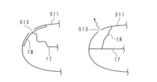
図8はアクティブベントの構成の第4例を示す模式図である。図8の例では、パッチ18を備える。パッチ18は、例えば、基布素材又は他の好適な布で形成することができ、パッチ18の形状は、ベント513を開放状態又は閉塞状態にできるものであれば、矩形、円形、三角形又は他の形状でもよい。パッチ18は、ベント513を塞ぐように、ベント513の周りに縫合又は接着されている。
FIG. 8 is a schematic diagram showing a fourth example of the configuration of the active vent. In the example of FIG. 8, a
ECU100がアクティブベントを閉塞状態とする制御信号を出力すると、テザー保持部16は、テザー17の一端を非保持する。テザー17は弛緩状態となる。パッチ18は、ベント513の周りに縫合又は接着された状態で維持され、エアバッグクッション部511は閉塞状態のまま膨張展開する。
When the
一方、ECU100がアクティブベントを開放状態とする制御信号を出力すると、テザー保持部16は、テザー17の一端を保持する。テザー17は引っ張られた状態となる。エアバッグクッション部511が膨張展開すると、パッチ18はテザー17により引っ張られ、ベント513の周りに縫合又は接着された部分の一部が開放状態となる。これにより、エアバッグクッション部511は開放状態となって膨張展開する。
On the other hand, when the
上述のように、アクティブベントは、エアバッグクッション部511に設けられたベント513を開放状態又は閉塞状態にするパッチ18を備える。エアバッグクッション部521、611、621それぞれに設けられたアクティブベントも同様である。パッチ18は、例えば、基布素材又は他の好適な布で形成することができ、形状は、ベント513を開放状態又は閉塞状態にできるものであれば、矩形、円形、三角形又は他の適宜の形状とすることができる。
As mentioned above, the active vent comprises a
エアバッグクッション部511は、一端がパッチ18に接続され、他端がテザー保持部16に接続されるテザー17を備える。エアバッグクッション部521、611、621も同様である。テザー17は、例えば、ナイロン織布などのように硬く強度がある素材で形成することができ、紐状又は帯状の形状をなす。テザー保持部16は、例えば、アクチュエータ等で構成することができ、ECU100が出力する制御信号に基づいて、テザー17の他端を保持又は非保持することができる。
The
テザー保持部16がテザー17を保持又は非保持することにより、パッチ18がベント513を開放状態又は閉塞状態のいずれかの状態にすることができる。例えば、テザー保持部16がテザー17を保持することにより、膨張展開するエアバッグクッション部511内のテザー17を張った状態にすることにより、図8のように、パッチ18をベント513から離脱させてベント513を開放状態にしてもよく、あるいは、図示していないが、パッチ18をベント513に密着させてベント513を閉塞状態にしてもよい。また、テザー保持部16がテザー17を非保持することにより、膨張展開するエアバッグクッション部511内のテザー17を弛緩状態にすることにより、図8に示すように、パッチ18をベント513に密着させてベント513を閉塞状態にしてもよく、図示していないが、パッチ18をベント513から離脱させてベント513を開放状態にしてもよい。これにより、ECU100が出力する制御信号に応じて、エアバッグクッション部511、521、611、621それぞれを個別独立に開放状態にすることも、閉塞状態にすることも可能となる。
The
図9A及び図9Bはアクティブベントの構成の第5例を示す模式図である。図9Aは、前述の図8の第4例を別の角度から見た模式図を示す。図9Aに示すように、エアバッグクッション部511が閉塞状態である場合、テザー17は弛緩状態となり、パッチ18はベント513を塞いだ状態でベント513の周りに縫合又は接着された状態となっている。一方、エアバッグクッション部511が開放状態である場合、テザー17は引っ張られたとなり、パッチ18はテザー17によって引っ張られ、ベント513の周りに縫合又は接着された部分の一部が外れて、ベント513は開放状態となっている。
9A and 9B are schematic diagrams showing a fifth example of the configuration of active vents. FIG. 9A shows a schematic diagram of the above-described fourth example of FIG. 8 viewed from another angle. As shown in FIG. 9A, when the
図9Bは、図9Aと同じ方向から見た場合の第5例を示す。図9Bでは、テザー17が引っ張られる方向を、仮にX軸方向とすると、ベント513の位置がX軸又はX軸の近傍に位置する構成(図9A)に代えて、ベント513がテザー17の位置からY軸方向にずれた位置に設けられてる。図9Bの構成にすることにより、エアバッグクッション部511が膨張展開してテザー17が引っ張られた状態になった場合に、パッチ18の一部が直ちにベント513から外れることがなく、しばらくの間はベント513が塞がれた状態が継続するので、エアバッグクッション部511のY方向への膨張展開の速度を速くすることができる。
FIG. 9B shows a fifth example when viewed from the same direction as FIG. 9A. In FIG. 9B, if the direction in which the
図10はアクティブベントの構成の第6例を示す模式図である。図10の例では、エアバッグクッション部511は、バッフル515を備える。バッフル515は、例えば、所要の基布で形成することができ、板状に形成された基布にベント513を形成しておき、折り畳むことによりベント513を塞いだ状態にし、展開された状態でベント513を開放した状態にすることができる。テザー17によってバッフル515を締め付けることにより、バッフル515を折り畳んだ状態にすることができ、テザー17を緩めることによりバッフル515を展開可能にしてベント513を開放した状態にすることができる。
FIG. 10 is a schematic diagram showing a sixth example of the configuration of the active vent. In the example of FIG. 10,
ECU100がアクティブベントを閉塞状態とする制御信号を出力すると、テザー保持部16は、テザー17の一端を保持する。テザー17は引っ張られた状態となる。バッフル515は、テザー17によって締め付けられた状態を維持し、ベント513は塞がれた状態のままとなる。エアバッグクッション部511は閉塞状態のまま膨張展開する。
When the
一方、ECU100がアクティブベントを開放状態とする制御信号を出力すると、テザー保持部16は、テザー17の一端を非保持する。テザー17は弛緩状態となる。バッフル515は、展開してベント513は開放状態となる。これにより、エアバッグクッション部511は開放状態となって膨張展開する。
On the other hand, when the
図11はアクティブベントの構成の第7例を示す模式図である。図11の例では、エアバッグクッション部511は、ベント181aが形成された帯状のパッチ181、及びベント182aが形成され、パッチ181を内部に挿通させて摺動可能に保持するガイド182を備える。パッチ181とガイド182との相対位置が変わることによって、ベント181aの位置とベント182aの位置とが全部又は一部重なると、ベントは開放状態になり、ベント181aの位置とベント182aの位置とが完全にずれると(全く重ならない)、ベントは閉塞状態となる。
FIG. 11 is a schematic diagram showing a seventh example of the configuration of the active vent. In the example of FIG. 11, the
ECU100がアクティブベントを閉塞状態とする制御信号を出力すると、テザー保持部16は、テザー17の一端を非保持する。テザー17は弛緩状態となる。パッチ181とガイド182との相対位置は維持され、ベント181aの位置とベント182aの位置とが完全にずれた状態となる。エアバッグクッション部511は閉塞状態のまま膨張展開する。
When the
一方、ECU100がアクティブベントを開放状態とする制御信号を出力すると、テザー保持部16は、テザー17の一端を保持する。テザー17は引っ張られた状態となる。エアバッグクッション部511が膨張展開するにつれて、パッチ181とガイド182との相対位置が変わり、ベント181aの位置とベント182aの位置とが全部又は一部重なり、ベントは開放状態になる。これにより、エアバッグクッション部511は開放状態となって膨張展開する。
On the other hand, when the
次に、乗員の頭部保護用の頭部クッション部について説明する。 Next, the head cushion portion for protecting the occupant's head will be described.
エアバッグクッション部511には、乗員の頭部保護用の頭部クッション部517が設けられている。同様に、エアバッグクッション部521、611、621にも頭部クッション部が設けられている。例えば、エアバッグクッション部511、521が膨張展開する際に、エアバッグクッション部511に設けられた頭部クッション部及びエアバッグクッション部521に設けられた頭部クッション部のいずれか一方を膨張展開させることができる。同様に、エアバッグクッション部611、621が膨張展開する際に、エアバッグクッション部611に設けられた頭部クッション部及びエアバッグクッション部621に設けられた頭部クッション部のいずれか一方を膨張展開させることができる。なお、他方の頭部クッション部は、膨張展開させず、例えば、エアバッグクッション部の内部に収容した状態とすることができる。
The
上述の構成により、座席の両側に設置された第1のエアバッグクッション部及び第2のエアバッグクッション部のいずれか一方に設けられた頭部クッション部は内部の圧力を自動的に開放しながら乗員を拘束することができ、他方に設けられた頭部クッション部は圧力を保持して乗員を拘束することができ、乗員の拘束性能を向上することができる。 With the above-described configuration, the head cushion provided on either the first airbag cushion or the second airbag cushion provided on both sides of the seat automatically releases internal pressure. The occupant can be restrained, and the head cushion portion provided on the other side can hold pressure and restrain the occupant, so that the occupant restraint performance can be improved.
図12は衝突時における頭部クッション部の状態の第1例を示す模式図である。以下では、エアバッグクッション部511について説明するが、他のエアバッグクッション部521、611、621についても同様である。図12に示すように、エアバッグクッション部511が閉塞状態に制御された場合、エアバッグクッション部511に設けられた頭部クッション部517を膨張展開させる。また、エアバッグクッション部511が開放状態に制御された場合、エアバッグクッション部511に設けられた頭部クッション部517を展開させない。すなわち、第1のエアバッグクッション部及び第2のエアバッグクッション部のいずれか一方が閉塞状態に制御された場合、閉塞状態に制御されたエアバッグクッション部に設けられた頭部クッション部を膨張展開させる。エアバッグクッション部を閉塞状態にする場合、乗員の位置は、エアバッグクッション部に対して正常な位置(近い位置ではない)にあるので、乗員の頭部を保護すべく頭部クッション部を膨張展開させる。これにより、乗員の拘束性能を向上することができる。
FIG. 12 is a schematic diagram showing a first example of the state of the head cushion portion at the time of collision. Although the
より具体的には、頭部クッション部517の全部又は一部はエアバッグクッション部511の内側に収容してある。例えば、頭部クッション部517の全部又は一部はエアバッグクッション部511の内側に向けて折り曲げてある。折り曲げられた部分をタックインされた部分とも称する。他のエアバッグクッション部521、611、621についても同様である。
More specifically, all or part of the
図12に示すように、閉塞状態に制御されたエアバッグクッション部511の内部のガスによって、エアバッグクッション部511の内側に収容された頭部クッション部517を膨張展開させる。エアバッグクッション部511を閉塞状態に制御することにより、膨張展開時のエアバッグクッション部511内の圧力が一定以上高くなると、エアバッグクッション部511内のガスが頭部クッション部517に流入して、エアバッグクッション部511の内側に収容された頭部クッション部517がエアバッグクッション部511の外側に向かって展開(拡がり)、頭部クッション部517を膨張展開させることができる。なお、この場合、テザー保持部16がテザー17を保持することにより、アクティブベント512はベント513を閉塞状態にする。
As shown in FIG. 12, the
また、テザー保持部16がテザー17を非保持することにより、アクティブベント512はベント513を開放状態にする。エアバッグクッション部511を開放状態に制御することにより、膨張展開時のエアバッグクッション部511内の圧力が高くならず、頭部クッション部517は、エアバッグクッション部511内部に収容された状態のままとなる。
In addition, the
図13は衝突時における頭部クッション部の状態の第2例を示す模式図である。第2例の場合も第1例の場合と同様に、頭部クッション部517の全部又は一部はエアバッグクッション部511の内側に収容してある。例えば、頭部クッション部517の全部又は一部はエアバッグクッション部511の内側に向けて折り曲げてある。第2例では、テザー17の一端がテザー保持部16に接続され、テザー17の他端は頭部クッション部517の所要の位置に接続されている。
FIG. 13 is a schematic diagram showing a second example of the state of the head cushion portion at the time of collision. In the case of the second example, as in the case of the first example, all or part of the
図13に示す閉塞状態の場合、頭部クッション部517を膨張展開させる。例えば、インフレータ15によって供給されたガスによって頭部クッション部517を膨張展開するさせることができる。具体的には、テザー保持部16がテザー17を非保持することにより、頭部クッション部517を膨張展開させることができる。この場合、頭部クッション部517が膨張展開するためエアバッグクッション部511の内部の圧力が所定値よりも高くならず、アクティブベント512はベント513を閉塞状態のままにするので、エアバッグクッション部511を閉塞状態にすることができる。
In the closed state shown in FIG. 13, the
図13に示す開放状態の場合、頭部クッション部517はエアバッグクッション部511の内側に収容されたままである。具体的には、テザー保持部16がテザー17を保持することにより、頭部クッション部517をエアバッグクッション部511の内側に収容したままにできる。この場合、頭部クッション部517が展開しないためエアバッグクッション部511の内部の圧力が所定値よりも高くなり、当該圧力により、アクティブベント512はベント513を開放状態にするので、エアバッグクッション部511を開放状態にすることができる。
In the open state shown in FIG. 13, the
上述の実施の形態において、エアバッグクッション部511及びエアバッグクッション部521は、膨張展開していない状態において、同一の袋状(同一形状)とすることができる。膨張展開していない状態とは、エアバッグクッション部511、521がアセンブリされた状態(製作された状態)で、例えば、平面上に展開された状態とすることができる。同様に、エアバッグクッション部611及びエアバッグクッション部621も、膨張展開していない状態において、同一の袋状とすることができる。
In the above-described embodiment, the
これにより、座席の両側に設置された第1のエアバッグクッション部及び第2のエアバッグクッション部のいずも同じように圧力を自動的に開放しながら乗員を拘束することができ、第1のエアバッグクッション部及び第2のエアバッグクッション部のいずも同じように圧力を保持して乗員を拘束することができる。 As a result, both the first airbag cushion portion and the second airbag cushion portion installed on both sides of the seat can similarly restrain the occupant while automatically releasing the pressure. Both the first airbag cushion portion and the second airbag cushion portion can similarly hold pressure to restrain the occupant.
上述の実施の形態において、エアバッグクッション部511、521、611、621それぞれは、膨張展開状態において、エアバッグクッション部内にガスを供給する開口部に対向させてアクティブベントを配置することができる。ここで、開口部は、例えば、インフレータ15、25のガス供給口でもよく、あるいはエアバッグクッション部511、521、611、621内部において、インフレータ15、25を覆う隔壁を備える場合、隔壁に設けられたガス供給口でもよい。
In the above-described embodiments, each of the
これにより、衝突時などにエアバッグクッション部内に開口部からガスを供給させてエアバッグクッション部を膨張展開させるときに、開口部から供給されるガスが直ちにアクティブベントから開放されることを抑止することができ、エアバッグクッション部が所要の状態(例えば、所要の形状、所要の内部圧力)になるように膨張展開させることができる。 This prevents the gas supplied from the opening from being immediately released from the active vent when the airbag cushion is inflated and deployed by supplying gas from the opening into the airbag cushion in the event of a collision or the like. It is possible to inflate and deploy the airbag cushion portion to a desired state (for example, desired shape, desired internal pressure).
次に、車両1内の座席の配置について説明する。
Next, the arrangement of seats in the
図14は運転席10及び助手席20の第3配置例の場合の衝突時におけるエアバッグクッション部の状態の一例を示す模式図である。第3配置例は、運転席10及び助手席20が向き合っている場合であり、例えば、自動運転中であり、運転席10及び助手席20に着座している乗員が向き合った状態である。また、運転席10及び助手席20の車長方向の相対位置を適宜ずらすこともできる。なお、図では、開放状態のアクティブベントには、ガスが抜けている様子を模式的に示す矢印を図示し、閉塞状態のアクティブベントには、矢印を付していない。
FIG. 14 is a schematic diagram showing an example of the state of the airbag cushion portion at the time of collision in the case of the third arrangement example of the driver's
車両1のボディ2又はインパネに近い方のエアバッグクッション部511、611は、膨張展開時に乗員の位置がエアバッグクッション部511、611に近くなる傾向があるため、エアバッグクッション部511、611内の圧力を自動的に開放しながら乗員を拘束することが望ましい。また、ボディ2から遠い方又は車内側のエアバッグクッション部521、621は、膨張展開時に乗員の位置がエアバッグクッション部521、621に対して正常な位置にある傾向があるので、エアバッグクッション部521、621内の圧力を保持して乗員を拘束することが望ましい。
The
そこで、車両1のボディ2又はインパネに近い方のエアバッグクッション部511、611に設けられたアクティブベント512、612を開放状態に制御し、ボディ2から遠い方又は車内側のエアバッグクッション部521、621に設けられたアクティブベント522、622を閉塞状態に制御することにより、車両1内で運転席10又は助手席20が回転した場合でも、乗員の拘束性能を向上することができる。
Therefore, the
図15は運転席10及び助手席20の第4配置例の場合の衝突時におけるエアバッグクッション部の状態の一例を示す模式図である。第4配置例は、運転席10及び助手席20が後方を向き、かつ向き合っている場合であり、例えば、自動運転中であり、運転席10及び助手席20に着座している乗員が後方かつお互いに向いている状態である。第4配置例の場合は、第2配置例の場合と同様の制御を行うことができるので、説明は省略する。
FIG. 15 is a schematic diagram showing an example of the state of the airbag cushion portion at the time of collision in the case of the fourth arrangement example of the driver's
図16は運転席10及び助手席20の第5配置例の場合の衝突時におけるエアバッグクッション部の状態の一例を示す模式図である。第5配置例は、運転席10及び助手席20の他に、後部席30も分離、移動が可能である場合の一例を示し、例えば、自動運転中である。運転席10及び助手席20の配置例は、図14の第3配置例と同様であるので、第3配置例と同様の制御を行うことができる。
FIG. 16 is a schematic diagram showing an example of the state of the airbag cushion portion at the time of a collision in the case of the fifth arrangement example of the driver's
図16に示すように、後部席30は、第1後部席30aと第2後部席30bとに分離することができ、第1後部席30aと第2後部席30bとが向き合っている場合であり、第1後部席30a及び第2後部席30bに着座している乗員も向き合った状態である。この場合、運転席10及び助手席20の場合と同様に、後部席30の分離や移動を検出できる後部席回転位置検出部を備えることができる。
As shown in FIG. 16, the
車両1のリア側のボディ2に近い方のエアバッグクッション部321a、321bは、膨張展開時に乗員の位置がエアバッグクッション部321a、321bに近くなる傾向があるため、エアバッグクッション部321a、321b内の圧力を自動的に開放しながら乗員を拘束することが望ましい。また、リア側のボディ2から遠い方又は車内側のエアバッグクッション部311a、311bは、膨張展開時に乗員の位置がエアバッグクッション部311a、311bに対して正常な位置にある傾向があるので、エアバッグクッション部311a、311b内の圧力を保持して乗員を拘束することが望ましい。
The
そこで、車両1のリア側のボディ2に近い方のエアバッグクッション部321a、321bに設けられたアクティブベント322a、322bを開放状態に制御し、リア側のボディ2から遠い方又は車内側のエアバッグクッション部311a、311bに設けられたアクティブベント312a、312bを閉塞状態に制御することにより、車両1内で後部席30が移動した場合でも、乗員の拘束性能を向上することができる。
Therefore, the
本実施の形態のエアバッグ装置は、車両のシートの両側それぞれに設置される第1のエアバッグクッション部及び第2のエアバッグクッション部と、前記第1のエアバッグクッション部に設けられた第1のアクティブベント及び前記第2のエアバッグクッション部に設けられた第2のアクティブベントと、前記第1のエアバッグクッション部及び第2のエアバッグクッション部が膨張展開する際に、前記第1のアクティブベント及び前記第2のアクティブベントのいずれか一方を開放状態に制御し、他方を閉塞状態に制御する制御部とを備える。 The airbag device of this embodiment includes a first airbag cushion portion and a second airbag cushion portion provided on both sides of a vehicle seat, and a second airbag cushion portion provided on the first airbag cushion portion. When the first active vent and the second active vent provided in the second airbag cushion portion, the first airbag cushion portion and the second airbag cushion portion are inflated and deployed, the first and a control unit that controls one of the active vent and the second active vent to be open and the other to be closed.
車両のシートの両側には第1のエアバッグクッション部及び第2のエアバッグクッション部が設置され、第1のアクティブベントが第1のエアバッグクッション部に設けられ、第2のアクティブベントが第2のエアバッグクッション部に設けられている。制御部は、車両の衝突時などに、第1のエアバッグクッション部及び第2のエアバッグクッション部が膨張展開する際に、第1のアクティブベント及び第2のアクティブベントのいずれか一方を開放状態に制御し、他方を閉塞状態に制御する。 A first airbag cushion part and a second airbag cushion part are installed on both sides of the vehicle seat, a first active vent is provided on the first airbag cushion part, and a second active vent is provided on the second airbag cushion part. 2 is provided in the airbag cushion portion. The control unit opens one of the first active vent and the second active vent when the first airbag cushion portion and the second airbag cushion portion are inflated and deployed in a vehicle collision or the like. one state and the other to a closed state.
アクティブベントが設けられたエアバッグクッション部は、車両の衝突時などに、インフレータ(ガス発生装置)によって供給されたガスによって膨張展開する。エアバッグクッション部に設けられたアクティブベントを開放状態にすると、エアバッグクッション部の膨張展開の開始時又は膨張展開の初期の段階において、エアバッグクッション部内の圧力を自動的に開放しながら乗員を拘束することができる。これにより、乗員が、膨張展開するエアバッグクッション部に近い位置(正常でない位置)にある場合などに、エアバッグクッション部の圧力を開放しつつ乗員を拘束することができる。 An airbag cushion provided with an active vent is inflated and deployed by gas supplied by an inflator (gas generator) at the time of a vehicle collision or the like. When the active vent provided in the airbag cushion is opened, the occupant is relieved while the pressure inside the airbag cushion is automatically released at the start of inflation and deployment of the airbag cushion or at the initial stage of inflation and deployment. can be constrained. As a result, when the occupant is in a position (abnormal position) near the inflating and deploying airbag cushion, the occupant can be restrained while the pressure of the airbag cushion is released.
一方、エアバッグクッション部に設けられたアクティブベントを閉塞状態にすると、エアバッグクッション部の膨張展開時において、エアバッグクッション部内の圧力を保持しながら乗員を拘束することができる。これにより、乗員が、膨張展開するエアバッグクッション部に対して正常な位置にある場合などに、エアバッグクッション部の圧力を保持して乗員を拘束することができる。 On the other hand, when the active vent provided in the airbag cushion is closed, the occupant can be restrained while the pressure inside the airbag cushion is maintained when the airbag cushion is inflated and deployed. As a result, when the occupant is in a normal position with respect to the inflating and deploying airbag cushion, the occupant can be restrained by maintaining the pressure of the airbag cushion.
上述の構成により、車両のシートの両側に設置された第1のエアバッグクッション部及び第2のエアバッグクッション部のいずれか一方はエアバッグクッション部内の圧力を自動的に開放しながら乗員を拘束することができ、他方はエアバッグクッション部の圧力を保持して乗員を拘束することができ、乗員の拘束性能を向上することができる。 With the above configuration, either one of the first airbag cushion and the second airbag cushion installed on both sides of the vehicle seat restrains the occupant while automatically releasing the pressure in the airbag cushion. On the other hand, the pressure of the airbag cushion portion can be maintained to restrain the occupant, and the restraint performance of the occupant can be improved.
本実施の形態のエアバッグ装置において、前記制御部は、車両内で移動可能に設けられた前記シートの移動位置に応じて、前記第1のアクティブベント及び前記第2のアクティブベントのいずれか一方を開放状態に制御し、他方を閉塞状態に制御する。 In the airbag device according to the present embodiment, the controller controls one of the first active vent and the second active vent according to the movement position of the seat movably provided in the vehicle. is controlled to be open and the other is controlled to be closed.
制御部は、車両内で移動可能に設けられたシートの移動位置に応じて、第1のアクティブベント及び第2のアクティブベントのいずれか一方を開放状態に制御し、他方を閉塞状態に制御する。移動可能は、例えば、回転移動、直線移動などを含む。シートの移動位置が変わることにより、シートの幅方向(車幅方向)の一方と他方とで、膨張展開するエアバッグクッション部に対する乗員の位置が、正常な位置(あるいは、より正常な位置)となるか、正常でない位置(あるいは、より正常でない位置)となるかが変わり得る。 The control unit controls one of the first active vent and the second active vent to open and the other to close according to the movement position of the seat movably provided in the vehicle. . Movable includes, for example, rotational movement, linear movement, and the like. By changing the movement position of the seat, the position of the occupant with respect to the inflating and deploying airbag cushion is changed from a normal position (or a more normal position) in one and the other width direction of the seat (vehicle width direction). or a non-normal position (or a less normal position).
そこで、シートの移動位置に応じて、第1のアクティブベント及び第2のアクティブベントのいずれか一方を開放状態に制御し、他方を閉塞状態に制御することにより、車両内でシートが移動した場合でも、乗員の拘束性能を向上することができる。 Therefore, one of the first active vent and the second active vent is controlled to be open and the other is controlled to be closed according to the movement position of the seat. However, the occupant restraint performance can be improved.
本実施の形態のエアバッグ装置において、前記制御部は、前記シートの回転位置に応じて、前記第1のエアバッグクッション部及び第2のエアバッグクッション部のうち、車両のボディに近い方のエアバッグクッション部に設けられたアクティブベントを開放状態に制御し、前記ボディから遠い方のエアバッグクッション部に設けられたアクティブベントを閉塞状態に制御する。 In the airbag device according to the present embodiment, the control section controls which of the first airbag cushion section and the second airbag cushion section closer to the vehicle body is adjusted in accordance with the rotational position of the seat. The active vent provided in the airbag cushion portion is controlled to open state, and the active vent provided in the airbag cushion portion farther from the body is controlled to closed state.
制御部は、シートの回転位置に応じて、第1のエアバッグクッション部及び第2のエアバッグクッション部のうち、車両のボディに近い方のエアバッグクッション部に設けられたアクティブベントを開放状態に制御し、ボディから遠い方のエアバッグクッション部に設けられたアクティブベントを閉塞状態に制御する。 The control unit opens an active vent provided in the airbag cushion portion closer to the vehicle body, out of the first airbag cushion portion and the second airbag cushion portion, according to the rotational position of the seat. , and the active vent provided in the airbag cushion part farther from the body is controlled to be in a closed state.
シートの回転位置は、例えば、乗員が車両の前方を向いている通常時の位置や、乗員が車両の後方を向いている反転時の位置などを含む。シートの回転位置に関わらず、車両のボディに近い方のエアバッグクッション部は、膨張展開時に乗員の位置がエアバッグクッション部に近くなる傾向があるため、エアバッグクッション部内の圧力を自動的に開放しながら乗員を拘束することが望ましい。また、ボディから遠い方のエアバッグクッション部は、膨張展開時に乗員の位置がエアバッグクッション部に対して正常な位置にある傾向があるので、エアバッグクッション部内の圧力を保持して乗員を拘束することが望ましい。 The rotational position of the seat includes, for example, a normal position in which the occupant faces the front of the vehicle, and a reversed position in which the occupant faces the rear of the vehicle. Regardless of the rotational position of the seat, the airbag cushion closer to the vehicle body tends to be closer to the airbag cushion when the occupant is inflated and deployed, so the pressure inside the airbag cushion is automatically reduced. It is desirable to restrain the occupant while opening. In addition, since the position of the occupant tends to be normal with respect to the airbag cushion when the airbag cushion is inflated and deployed, the airbag cushion that is farther from the body retains the pressure inside the airbag cushion and restrains the occupant. It is desirable to
そこで、車両のボディに近い方のエアバッグクッション部に設けられたアクティブベントを開放状態に制御し、ボディから遠い方のエアバッグクッション部に設けられたアクティブベントを閉塞状態に制御することにより、車両内でシートが回転した場合でも、乗員の拘束性能を向上することができる。 Therefore, by controlling the active vent provided in the airbag cushion portion closer to the vehicle body to the open state and controlling the active vent provided in the airbag cushion portion farther from the body to the closed state, Even if the seat rotates in the vehicle, the occupant restraint performance can be improved.
本実施の形態のエアバッグ装置は、前記第1のエアバッグクッション部に設けられ、乗員の頭部保護用の第1の頭部クッション部と、前記第2のエアバッグクッション部に設けられ、乗員の頭部保護用の第2の頭部クッション部とを備え、前記第1のエアバッグクッション部及び第2のエアバッグクッション部が膨張展開する際に、前記第1の頭部クッション部及び前記第2の頭部クッション部のいずれか一方を膨張展開させる。 The airbag device of the present embodiment is provided in the first airbag cushion portion, provided in the first head cushion portion for protecting the occupant's head, and in the second airbag cushion portion, and a second head cushion portion for protecting the head of an occupant, wherein when the first airbag cushion portion and the second airbag cushion portion are inflated and deployed, the first head cushion portion and Either one of the second head cushion portions is inflated and deployed.
乗員の頭部保護用の第1の頭部クッション部は、第1のエアバッグクッション部に設けられ、第2の頭部クッション部は、第2のエアバッグクッション部に設けられている。第1のエアバッグクッション部及び第2のエアバッグクッション部が膨張展開する際に、第1の頭部クッション部及び第2の頭部クッション部のいずれか一方を膨張展開させる。なお、他方の頭部クッション部は、膨張展開させず、例えば、エアバッグクッション部の内部に収容した状態とすることができる。 A first head cushion portion for protecting the occupant's head is provided on the first airbag cushion portion, and a second head cushion portion is provided on the second airbag cushion portion. When the first airbag cushion portion and the second airbag cushion portion are inflated and deployed, either one of the first head cushion portion and the second head cushion portion is inflated and deployed. Note that the other head cushion portion can be in a state of being accommodated inside the airbag cushion portion, for example, without being inflated and deployed.
上述の構成により、車両のシートの両側に設置された第1のエアバッグクッション部及び第2のエアバッグクッション部のいずれか一方に設けられた頭部クッション部は内部の圧力を自動的に開放しながら乗員を拘束することができ、他方に設けられた頭部クッション部は圧力を保持して乗員を拘束することができ、乗員の拘束性能を向上することができる。 With the above configuration, the head cushion provided on either the first airbag cushion or the second airbag cushion provided on both sides of the vehicle seat automatically releases the internal pressure. The head cushion provided on the other side can restrain the occupant while holding the pressure and restrain the occupant, so that the occupant restraint performance can be improved.
本実施の形態のエアバッグ装置は、前記第1のエアバッグクッション部及び第2のエアバッグクッション部のいずれか一方が閉塞状態に制御された場合、閉塞状態に制御されたエアバッグクッション部に設けられた頭部クッション部を膨張展開させる。 In the airbag device of the present embodiment, when one of the first airbag cushion portion and the second airbag cushion portion is controlled to be in the closed state, the airbag cushion portion controlled to be in the closed state The provided head cushion portion is inflated and deployed.
第1のエアバッグクッション部及び第2のエアバッグクッション部のいずれか一方が閉塞状態に制御された場合、閉塞状態に制御されたエアバッグクッション部に設けられた頭部クッション部を膨張展開させる。エアバッグクッション部を閉塞状態にする場合、乗員の位置は、エアバッグクッション部に対して正常な位置(近い位置ではない)にあるので、乗員の頭部を保護すべく頭部クッション部を膨張展開させる。これにより、乗員の拘束性能を向上することができる。 When either one of the first airbag cushion portion and the second airbag cushion portion is controlled to be in the closed state, the head cushion portion provided in the airbag cushion portion controlled to be in the closed state is inflated and deployed. . When closing the airbag cushion, the occupant is in a normal position (not close) to the airbag cushion, so the head cushion is inflated to protect the occupant's head. unfold. Thereby, the occupant restraint performance can be improved.
本実施の形態のエアバッグ装置は、前記第1の頭部クッション部の全部又は一部は前記第1のエアバッグクッション部の内側に収容してあり、前記第2の頭部クッション部の全部又は一部は前記第2のエアバッグクッション部の内側に収容してあり、前記閉塞状態に制御されたエアバッグクッション部の内部のガスによって、該エアバッグクッション部の内側に収容された頭部クッション部を膨張展開させる。 In the airbag device of this embodiment, all or part of the first head cushion portion is accommodated inside the first airbag cushion portion, and the entire second head cushion portion is housed inside the first airbag cushion portion. Or part of it is housed inside the second airbag cushion, and the head housed inside the airbag cushion is caused by the gas inside the airbag cushion that is controlled to be in the closed state. Inflate and deploy the cushion.
第1の頭部クッション部の全部又は一部は第1のエアバッグクッション部の内側に収容してある。例えば、第1の頭部クッション部の全部又は一部は第1のエアバッグクッション部の内側に向けて折り曲げてある。折り曲げられた部分をタックインされた部分とも称する。第2の頭部クッション部の全部又は一部は第2のエアバッグクッション部の内側に収容してある。例えば、第2の頭部クッション部の全部又は一部は第2のエアバッグクッション部の内側に向けて折り曲げてある。 All or part of the first head cushion portion is housed inside the first airbag cushion portion. For example, all or part of the first head cushion portion is folded toward the inside of the first airbag cushion portion. The folded portion is also called a tucked-in portion. All or part of the second head cushion portion is housed inside the second airbag cushion portion. For example, all or part of the second head cushion portion is folded toward the inside of the second airbag cushion portion.
閉塞状態に制御されたエアバッグクッション部の内部のガスによって、エアバッグクッション部の内側に収容された頭部クッション部を膨張展開させる。エアバッグクッション部を閉塞状態に制御することにより、膨張展開時のエアバッグクッション部内の圧力が一定以上高くなると、エアバッグクッション部内のガスが頭部クッション部に流入して、エアバッグクッション部の内側に収容された頭部クッション部がエアバッグクッション部の外側に向かって展開(拡がり)、頭部クッション部を膨張展開させることができる。 The gas inside the airbag cushion controlled to the closed state inflates and deploys the head cushion accommodated inside the airbag cushion. By controlling the airbag cushion to a closed state, if the pressure inside the airbag cushion during inflation and deployment rises above a certain level, the gas inside the airbag cushion flows into the head cushion, causing the airbag cushion to close. The head cushion part housed inside can expand (expand) toward the outside of the airbag cushion part and inflate and deploy the head cushion part.
本実施の形態のエアバッグ装置は、前記第1の頭部クッション部の全部又は一部は前記第1のエアバッグクッション部の内側に収容してあり、前記第2の頭部クッション部の全部又は一部は前記第2のエアバッグクッション部の内側に収容してあり、前記第1の頭部クッション部又は前記第2の頭部クッション部のいずれか一方を膨張展開させることによって、膨張展開する頭部クッション部が収容されたエアバッグクッション部を閉塞状態にする。 In the airbag device of this embodiment, all or part of the first head cushion portion is accommodated inside the first airbag cushion portion, and the entire second head cushion portion is housed inside the first airbag cushion portion. Alternatively, part of the airbag cushion is housed inside the second airbag cushion, and is inflated and deployed by inflating and deploying either the first head cushion or the second head cushion. The airbag cushion part in which the head cushion part is accommodated is closed.
第1の頭部クッション部の全部又は一部は第1のエアバッグクッション部の内側に収容してある。例えば、第1の頭部クッション部の全部又は一部は第1のエアバッグクッション部の内側に向けて折り曲げてある。折り曲げられた部分をタックインされた部分とも称する。第2の頭部クッション部の全部又は一部は第2のエアバッグクッション部の内側に収容してある。例えば、第2の頭部クッション部の全部又は一部は第2のエアバッグクッション部の内側に向けて折り曲げてある。 All or part of the first head cushion portion is housed inside the first airbag cushion portion. For example, all or part of the first head cushion portion is folded toward the inside of the first airbag cushion portion. The folded portion is also called a tucked-in portion. All or part of the second head cushion portion is housed inside the second airbag cushion portion. For example, all or part of the second head cushion portion is folded toward the inside of the second airbag cushion portion.
第1の頭部クッション部又は第2の頭部クッション部のいずれか一方を膨張展開させる。例えば、インフレータ(ガス発生装置)によって供給されたガスによって第1の頭部クッション部又は第2の頭部クッション部のいずれか一方を膨張展開するさせることができる。頭部クッション部が膨張展開することにより、当該頭部クッション部を収容したエアバッグクッション部の内部の圧力が高くならず、アクティブベントを閉塞状態のままにすることができ、エアバッグクッション部を閉塞状態にすることができる。 Either the first head cushion portion or the second head cushion portion is inflated and deployed. For example, either the first head cushion portion or the second head cushion portion can be inflated and deployed by gas supplied by an inflator (gas generator). By inflating and deploying the head cushion portion, the pressure inside the airbag cushion portion containing the head cushion portion does not increase, the active vent can remain closed, and the airbag cushion portion can be closed. It can be closed.
本実施の形態のエアバッグ装置は、前記第1のエアバッグクッション部及び第2のエアバッグクッション部は、膨張展開していない状態において、同一の袋状をなす。 In the airbag device of the present embodiment, the first airbag cushion portion and the second airbag cushion portion form the same bag shape when not inflated and deployed.
第1のエアバッグクッション部及び第2のエアバッグクッション部は、膨張展開していない状態において、同一の袋状をなす。これにより、車両のシートの両側に設置された第1のエアバッグクッション部及び第2のエアバッグクッション部のいずも同じように圧力を自動的に開放しながら乗員を拘束することができ、第1のエアバッグクッション部及び第2のエアバッグクッション部のいずも同じように圧力を保持して乗員を拘束することができる。 The first airbag cushion portion and the second airbag cushion portion have the same bag-like shape when they are not inflated and deployed. As a result, both the first airbag cushion portion and the second airbag cushion portion installed on both sides of the vehicle seat can similarly restrain the occupant while automatically releasing the pressure. Both the first airbag cushion portion and the second airbag cushion portion can similarly hold pressure to restrain the occupant.
本実施の形態のエアバッグ装置において、前記第1のエアバッグクッション部及び第2のエアバッグクッション部それぞれは、膨張展開状態において、前記第1のエアバッグクッション部及び第2のエアバッグクッション部内にガスを供給する開口部に対向させて前記第1のアクティブベント及び前記第2のアクティブベントを配置してある。 In the airbag device of the present embodiment, the first airbag cushion portion and the second airbag cushion portion are arranged inside the first airbag cushion portion and the second airbag cushion portion in an inflated and deployed state. The first active vent and the second active vent are positioned opposite openings for supplying gas to the chamber.
第1のエアバッグクッション部及び第2のエアバッグクッション部それぞれは、膨張展開状態において、第1のエアバッグクッション部及び第2のエアバッグクッション部内にガスを供給する開口部に対向させて第1のアクティブベント及び第2のアクティブベントを配置してある。 Each of the first airbag cushion portion and the second airbag cushion portion, in an inflated and deployed state, faces the opening portion for supplying gas into the first airbag cushion portion and the second airbag cushion portion. There is one active vent and a second active vent.
これにより、衝突時などにエアバッグクッション部内に開口部からガスを供給させてエアバッグクッション部を膨張展開させるときに、開口部から供給されるガスが直ちにアクティブベントから開放されることを抑止することができ、エアバッグクッション部が所要の状態になるように膨張展開させることができる。 This prevents the gas supplied from the opening from being immediately released from the active vent when the airbag cushion is inflated and deployed by supplying gas from the opening into the airbag cushion in the event of a collision or the like. It is possible to inflate and deploy the airbag cushion portion to a desired state.
本実施の形態のエアバッグ装置において、前記第1のアクティブベント及び前記第2のアクティブベントそれぞれは、前記第1のエアバッグクッション部及び第2のエアバッグクッション部に設けられたベントを開放状態又は閉塞状態にするパッチを備え、前記第1のエアバッグクッション部及び第2のエアバッグクッション部それぞれは、一端が前記パッチに接続されるテザーと、前記テザーの他端が接続され、前記テザーを保持又は非保持するテザー保持部とを備え、前記テザー保持部が前記テザーを保持又は非保持することにより、前記パッチが前記ベントを開放状態又は閉塞状態のいずれかの状態にする。 In the airbag device of the present embodiment, the first active vent and the second active vent respectively open the vents provided in the first airbag cushion portion and the second airbag cushion portion. Alternatively, the first airbag cushion portion and the second airbag cushion portion each include a tether having one end connected to the patch and the other end of the tether connected to the tether. and a tether retainer that retains or does not retain the tether so that the patch either opens or closes the vent.
第1のアクティブベントは、第1のエアバッグクッション部に設けられたベントを開放状態又は閉塞状態にするパッチを備え、第2のアクティブベントは、第2のエアバッグクッション部に設けられたベントを開放状態又は閉塞状態にするパッチを備える。パッチは、例えば、基布素材又は他の好適な布で形成することができ、形状は、ベントを開放状態又は閉塞状態にできるものであれば、矩形、円形、三角形又は他の形状でもよい。 The first active vent comprises a patch for opening or closing a vent on the first airbag cushion portion, and the second active vent comprises a vent on the second airbag cushion portion. a patch that opens or closes the The patch may be formed, for example, from a backing material or other suitable fabric, and may be rectangular, circular, triangular, or any other shape that allows the vent to be open or closed.
第1のエアバッグクッション部及び第2のエアバッグクッション部それぞれは、一端がパッチに接続され、他端がテザー保持部に接続されるテザーを備える。テザーは、例えば、ナイロン織布などのように硬く強度がある素材で形成することができ、紐状又は帯状の形状をなす。テザー保持部は、例えば、アクチュエータ等で構成することができ、外部からの制御信号に基づいて、テザーの他端を保持又は非保持することができる。 Each of the first airbag cushion portion and the second airbag cushion portion includes a tether having one end connected to the patch and the other end connected to the tether retainer. The tether can be made of, for example, a hard and strong material such as nylon fabric, and has a string-like or belt-like shape. The tether holding part can be composed of, for example, an actuator or the like, and can hold or not hold the other end of the tether based on an external control signal.
テザー保持部がテザーを保持又は非保持することにより、パッチがベントを開放状態又は閉塞状態のいずれかの状態にする。例えば、テザー保持部がテザーを保持することにより、膨張展開するエアバッグクッション部内のテザーを張った状態にすることにより、パッチをベントに密着させてベントを閉塞状態にしてもよく、あるいはパッチをベントから離脱させてベントを開放状態にしてもよい。また、テザー保持部がテザーを非保持することにより、膨張展開するエアバッグクッション部内のテザーを弛緩状態にすることにより、パッチをベントに密着させてベントを閉塞状態にしてもよく、あるいはパッチをベントから離脱させてベントを開放状態にしてもよい。これにより、第1のエアバッグクッション部及び第2のエアバッグクッション部を開放状態にすることも、閉塞状態にすることも可能となる。 The tether retainer retains or does not retain the tether, causing the patch to either open or close the vent. For example, by holding the tether with the tether holding part, the tether in the airbag cushion part that is inflated and deployed may be in a taut state, so that the patch is brought into close contact with the vent and the vent is closed, or the patch may be closed. The vent may be opened by being disengaged from the vent. In addition, the tether holding portion does not hold the tether so that the tether in the airbag cushion portion that is inflated and deployed is in a relaxed state, so that the patch is brought into close contact with the vent and the vent is closed, or the patch is closed. The vent may be opened by being disengaged from the vent. As a result, the first airbag cushion portion and the second airbag cushion portion can be opened or closed.
1 車両
2 ボディ
3 ステアリングホイール
10 運転席
20 助手席
30 後部席
30a 第1後部席
30b 第2後部席
11、21、31 シートバック
12、22、32 ヘッドレスト
51、52、61、62 収容部
15、25 インフレータ
16 テザー保持部
17 テザー
18 パッチ
100 ECU
110 運転席回転位置検出部
120 助手席回転位置検出部
130 センサ
511、521、611、621、311a、311b、321a、321b エアバッグクッション部
512、522、612、622、312a、312b、322a、322b アクティブベント
513、181a、182a ベント
515 バッフル
181 パッチ
182 ガイド
517 頭部クッション部
516 縫製部
516a 切れ目
1
110 Driver's seat
Claims (9)
前記第1のエアバッグクッション部に設けられた第1のアクティブベント及び前記第2のエアバッグクッション部に設けられた第2のアクティブベントと、
前記第1のエアバッグクッション部及び第2のエアバッグクッション部が膨張展開する際に、前記第1のアクティブベント及び前記第2のアクティブベントのいずれか一方を開放状態に制御し、他方を閉塞状態に制御する制御部と、
前記第1のエアバッグクッション部に設けられ、乗員の頭部保護用の第1の頭部クッション部と、
前記第2のエアバッグクッション部に設けられ、乗員の頭部保護用の第2の頭部クッション部と
を備え、
前記第1のエアバッグクッション部及び第2のエアバッグクッション部が膨張展開する際に、前記第1の頭部クッション部及び前記第2の頭部クッション部のいずれか一方を膨張展開させるエアバッグ装置。 a first airbag cushion part and a second airbag cushion part respectively installed on both sides of a vehicle seat;
a first active vent provided in the first airbag cushion portion and a second active vent provided in the second airbag cushion portion;
When the first airbag cushion portion and the second airbag cushion portion are inflated and deployed, one of the first active vent and the second active vent is controlled to be opened and the other is closed. a controller that controls the state ;
a first head cushion portion provided in the first airbag cushion portion for protecting the occupant's head;
a second head cushion portion provided in the second airbag cushion portion for protecting the occupant's head;
with
air for inflating and deploying either the first head cushion portion or the second head cushion portion when the first airbag cushion portion and the second airbag cushion portion are inflated and deployed; bag device.
車両内で移動可能に設けられた前記シートの移動位置に応じて、前記第1のアクティブベント及び前記第2のアクティブベントのいずれか一方を開放状態に制御し、他方を閉塞状態に制御する請求項1に記載のエアバッグ装置。 The control unit
One of the first active vent and the second active vent is controlled to be opened and the other is controlled to be closed according to the movement position of the seat that is movably provided in the vehicle. Item 1. The airbag device according to item 1.
前記シートの回転位置に応じて、前記第1のエアバッグクッション部及び第2のエアバッグクッション部のうち、車両のボディに近い方のエアバッグクッション部に設けられたアクティブベントを開放状態に制御し、前記ボディから遠い方のエアバッグクッション部に設けられたアクティブベントを閉塞状態に制御する請求項2に記載のエアバッグ装置。 The control unit
An active vent provided in the airbag cushion portion closer to the vehicle body, out of the first airbag cushion portion and the second airbag cushion portion, is controlled to open according to the rotational position of the seat. 3. The airbag device according to claim 2, wherein the active vent provided in the airbag cushion portion farther from the body is controlled to be closed.
前記第2の頭部クッション部の全部又は一部は前記第2のエアバッグクッション部の内側に収容してあり、
前記閉塞状態に制御されたエアバッグクッション部の内部のガスによって、該エアバッグクッション部の内側に収容された頭部クッション部を膨張展開させる請求項4に記載されたエアバッグ装置。 All or part of the first head cushion portion is housed inside the first airbag cushion portion,
All or part of the second head cushion portion is accommodated inside the second airbag cushion portion,
5. The airbag device according to claim 4 , wherein the head cushion portion accommodated inside the airbag cushion portion is inflated and deployed by the gas inside the airbag cushion portion controlled to the closed state.
前記第2の頭部クッション部の全部又は一部は前記第2のエアバッグクッション部の内側に収容してあり、
前記第1の頭部クッション部又は前記第2の頭部クッション部のいずれか一方を膨張展開させることによって、膨張展開する頭部クッション部が収容されたエアバッグクッション部を閉塞状態にする請求項4に記載されたエアバッグ装置。 All or part of the first head cushion portion is housed inside the first airbag cushion portion,
All or part of the second head cushion portion is accommodated inside the second airbag cushion portion,
The air bag cushion part accommodating the inflating and deploying head cushion part is brought into a closed state by inflating and deploying either one of the first head cushion part and the second head cushion part. 4. The airbag device described in 4 .
膨張展開状態において、前記第1のエアバッグクッション部及び第2のエアバッグクッション部内にガスを供給する開口部に対向させて前記第1のアクティブベント及び前記第2のアクティブベントを配置してある請求項1から請求項7のいずれか一項に記載のエアバッグ装置。 Each of the first airbag cushion portion and the second airbag cushion portion
In an inflated and deployed state, the first active vent and the second active vent are arranged so as to face openings for supplying gas into the first airbag cushion portion and the second airbag cushion portion. The airbag device according to any one of claims 1 to 7 .
前記第1のエアバッグクッション部及び第2のエアバッグクッション部に設けられたベントを開放状態又は閉塞状態にするパッチを備え、
前記第1のエアバッグクッション部及び第2のエアバッグクッション部それぞれは、
一端が前記パッチに接続されるテザーと、
前記テザーの他端が接続され、前記テザーを保持又は非保持するテザー保持部と
を備え、
前記テザー保持部が前記テザーを保持又は非保持することにより、前記パッチが前記ベントを開放状態又は閉塞状態のいずれかの状態にする請求項1から請求項8のいずれか一項に記載のエアバッグ装置。 each of the first active vent and the second active vent,
A patch that opens or closes the vents provided in the first airbag cushion part and the second airbag cushion part,
Each of the first airbag cushion portion and the second airbag cushion portion
a tether having one end connected to the patch;
a tether holding part to which the other end of the tether is connected and which holds or does not hold the tether,
9. An air vent according to any one of claims 1 to 8 , wherein the tether retainer retains or does not retain the tether so that the patch either opens or closes the vent. bag device.
Applications Claiming Priority (3)
| Application Number | Priority Date | Filing Date | Title |
|---|---|---|---|
| JP2019083252 | 2019-04-24 | ||
| JP2019083252 | 2019-04-24 | ||
| PCT/JP2020/014285 WO2020217859A1 (en) | 2019-04-24 | 2020-03-27 | Airbag device |
Publications (2)
| Publication Number | Publication Date |
|---|---|
| JPWO2020217859A1 JPWO2020217859A1 (en) | 2020-10-29 |
| JP7247328B2 true JP7247328B2 (en) | 2023-03-28 |
Family
ID=72942468
Family Applications (1)
| Application Number | Title | Priority Date | Filing Date |
|---|---|---|---|
| JP2021515908A Active JP7247328B2 (en) | 2019-04-24 | 2020-03-27 | air bag device |
Country Status (6)
| Country | Link |
|---|---|
| US (1) | US11820319B2 (en) |
| EP (1) | EP3960552A4 (en) |
| JP (1) | JP7247328B2 (en) |
| KR (1) | KR102596501B1 (en) |
| CN (1) | CN113710546B (en) |
| WO (1) | WO2020217859A1 (en) |
Families Citing this family (4)
| Publication number | Priority date | Publication date | Assignee | Title |
|---|---|---|---|---|
| WO2020217859A1 (en) * | 2019-04-24 | 2020-10-29 | オートリブ ディベロップメント エービー | Airbag device |
| DE102019123622A1 (en) * | 2019-09-04 | 2021-03-04 | Zf Automotive Germany Gmbh | Occupant restraint system with a seat and vehicle with an occupant restraint system |
| US11110883B1 (en) * | 2020-07-08 | 2021-09-07 | Ford Global Technologies, Llc | Airbag assembly including a vent cover |
| WO2023157634A1 (en) * | 2022-02-16 | 2023-08-24 | オートリブ ディベロップメント エービー | Side airbag device and method for manufacturing same |
Citations (4)
| Publication number | Priority date | Publication date | Assignee | Title |
|---|---|---|---|---|
| JP2009040206A (en) | 2007-08-08 | 2009-02-26 | Takata Corp | Airbag and airbag device |
| JP2010006237A (en) | 2008-06-26 | 2010-01-14 | Nippon Plast Co Ltd | Side airbag device |
| WO2018167911A1 (en) | 2017-03-16 | 2018-09-20 | 本田技研工業株式会社 | Vehicle occupant protection control device, vehicle occupant protection control method, and program |
| JP2019006153A (en) | 2017-06-20 | 2019-01-17 | テイ・エス テック株式会社 | Vehicle seat |
Family Cites Families (24)
| Publication number | Priority date | Publication date | Assignee | Title |
|---|---|---|---|---|
| JPH081982Y2 (en) * | 1990-02-23 | 1996-01-24 | マツダ株式会社 | Energy absorption structure on the vehicle body side |
| JPH09136598A (en) * | 1995-11-16 | 1997-05-27 | Toyota Motor Corp | Chest and head integrating type air bag device |
| DE10142819B4 (en) * | 2001-08-22 | 2009-04-30 | Takata-Petri Ag | An air bag assembly |
| DE602004001528T2 (en) * | 2003-02-25 | 2007-02-22 | Takata Corp. | Child seat. |
| DE202006002605U1 (en) * | 2006-02-14 | 2006-05-11 | Takata-Petri (Ulm) Gmbh | Side airbag arrangement for occupant restraint system of vehicle has each inflatable element provided with longitudinal adjustment section of seat adaptable to at least one body characteristic of occupant |
| JP5104234B2 (en) * | 2007-11-09 | 2012-12-19 | タカタ株式会社 | Air bag and air bag device |
| ITVR20100042A1 (en) * | 2010-03-09 | 2011-09-10 | Dainese Spa | COVERAGE ASSEMBLY FOR A SEAT AND SEAT SUITABLE FOR A USER PROTECTION. |
| US8534704B2 (en) * | 2011-05-24 | 2013-09-17 | Trw Vehicle Safety Systems, Inc. | Active air bag vent |
| CN104039603B (en) | 2011-12-28 | 2017-02-15 | 丰田自动车株式会社 | Vehicle seat |
| JP5781985B2 (en) * | 2012-07-05 | 2015-09-24 | オートリブ ディベロップメント エービー | Side airbag device |
| JP5776648B2 (en) * | 2012-08-10 | 2015-09-09 | トヨタ自動車株式会社 | Crew protection device |
| JP6422911B2 (en) * | 2015-04-14 | 2018-11-14 | オートリブ ディベロップメント エービー | Side airbag device |
| US10131312B2 (en) * | 2016-02-16 | 2018-11-20 | Joyson Safety Systems Acquisition Llc | Center side airbag module |
| JP6271622B2 (en) * | 2016-03-18 | 2018-01-31 | 株式会社Subaru | Airbag device |
| US9650011B1 (en) * | 2016-05-04 | 2017-05-16 | Ford Global Technologies, Llc | Passenger airbag including deployable extensions |
| KR101931125B1 (en) * | 2016-11-21 | 2018-12-20 | 아우토리브 디벨롭먼트 아베 | Airbag apparatus of vehicle |
| US10369956B2 (en) * | 2017-03-20 | 2019-08-06 | Ford Global Technologies, Llc | Side airbag with necking chamber |
| KR102435980B1 (en) * | 2017-10-26 | 2022-08-26 | 현대자동차주식회사 | Curtain airbag system of vehicle |
| CN109334605B (en) * | 2018-09-10 | 2021-07-20 | 江苏大学 | Back row built-in safety airbag and control method thereof |
| US10730472B2 (en) * | 2018-10-23 | 2020-08-04 | Trw Vehicle Safety Systems Inc. | Airbag and method for protecting an occupant of a vehicle |
| KR102154195B1 (en) * | 2018-12-20 | 2020-09-09 | 아우토리브 디벨롭먼트 아베 | Airbag apparatus of vehicle |
| WO2020217859A1 (en) * | 2019-04-24 | 2020-10-29 | オートリブ ディベロップメント エービー | Airbag device |
| US11091111B2 (en) * | 2019-10-01 | 2021-08-17 | Ford Global Technologies, Llc | Side airbag including lower lobe and upper lobe |
| US11161473B2 (en) * | 2020-01-22 | 2021-11-02 | Ford Global Technologies, Llc | Side airbag assembly |
-
2020
- 2020-03-27 WO PCT/JP2020/014285 patent/WO2020217859A1/en unknown
- 2020-03-27 KR KR1020217037719A patent/KR102596501B1/en active IP Right Grant
- 2020-03-27 US US17/594,480 patent/US11820319B2/en active Active
- 2020-03-27 JP JP2021515908A patent/JP7247328B2/en active Active
- 2020-03-27 EP EP20795169.0A patent/EP3960552A4/en active Pending
- 2020-03-27 CN CN202080028688.8A patent/CN113710546B/en active Active
Patent Citations (4)
| Publication number | Priority date | Publication date | Assignee | Title |
|---|---|---|---|---|
| JP2009040206A (en) | 2007-08-08 | 2009-02-26 | Takata Corp | Airbag and airbag device |
| JP2010006237A (en) | 2008-06-26 | 2010-01-14 | Nippon Plast Co Ltd | Side airbag device |
| WO2018167911A1 (en) | 2017-03-16 | 2018-09-20 | 本田技研工業株式会社 | Vehicle occupant protection control device, vehicle occupant protection control method, and program |
| JP2019006153A (en) | 2017-06-20 | 2019-01-17 | テイ・エス テック株式会社 | Vehicle seat |
Also Published As
| Publication number | Publication date |
|---|---|
| US11820319B2 (en) | 2023-11-21 |
| WO2020217859A1 (en) | 2020-10-29 |
| CN113710546B (en) | 2023-09-12 |
| JPWO2020217859A1 (en) | 2020-10-29 |
| CN113710546A (en) | 2021-11-26 |
| KR102596501B1 (en) | 2023-11-01 |
| US20230054543A1 (en) | 2023-02-23 |
| KR20210153697A (en) | 2021-12-17 |
| EP3960552A1 (en) | 2022-03-02 |
| EP3960552A4 (en) | 2023-01-18 |
Similar Documents
| Publication | Publication Date | Title |
|---|---|---|
| JP7247328B2 (en) | air bag device | |
| US7506892B2 (en) | Cushion shaping sleeve and tether for airbags | |
| US8231140B2 (en) | Airbag module with deployment control flap | |
| US7156418B2 (en) | Method for folding airbag, airbag apparatus, and airbag | |
| JP4996550B2 (en) | Airbag device | |
| US7954850B2 (en) | Air bag with adaptive venting | |
| US10953840B2 (en) | Knee airbag arrangement comprising external tether | |
| US9120455B2 (en) | Airbag and airbag device | |
| US8746736B2 (en) | Airbag module | |
| JP6845922B2 (en) | Airbag device | |
| WO2008010885A1 (en) | Airbag with active exhaust vent | |
| JP2009143545A (en) | Air bag with deployment flap | |
| JP6726057B2 (en) | Airbag device | |
| US7201395B2 (en) | Knee-protecting airbag device | |
| JP2001171456A (en) | Air bag | |
| JP2021020655A (en) | Air bag device | |
| US11135993B2 (en) | Airbag arrangement | |
| JP6302768B2 (en) | Side airbag device | |
| JP7113389B2 (en) | side airbag device | |
| JP7169258B2 (en) | side airbag device | |
| JP6327112B2 (en) | Side airbag device | |
| JP2003170802A (en) | Air bag |
Legal Events
| Date | Code | Title | Description |
|---|---|---|---|
| A621 | Written request for application examination |
Free format text: JAPANESE INTERMEDIATE CODE: A621 Effective date: 20211012 |
|
| A131 | Notification of reasons for refusal |
Free format text: JAPANESE INTERMEDIATE CODE: A131 Effective date: 20221004 |
|
| A521 | Request for written amendment filed |
Free format text: JAPANESE INTERMEDIATE CODE: A523 Effective date: 20221108 |
|
| TRDD | Decision of grant or rejection written | ||
| A01 | Written decision to grant a patent or to grant a registration (utility model) |
Free format text: JAPANESE INTERMEDIATE CODE: A01 Effective date: 20230307 |
|
| A61 | First payment of annual fees (during grant procedure) |
Free format text: JAPANESE INTERMEDIATE CODE: A61 Effective date: 20230315 |
|
| R150 | Certificate of patent or registration of utility model |
Ref document number: 7247328 Country of ref document: JP Free format text: JAPANESE INTERMEDIATE CODE: R150 |