EP3960496A1 - Truck tire - Google Patents
Truck tire Download PDFInfo
- Publication number
- EP3960496A1 EP3960496A1 EP21194156.2A EP21194156A EP3960496A1 EP 3960496 A1 EP3960496 A1 EP 3960496A1 EP 21194156 A EP21194156 A EP 21194156A EP 3960496 A1 EP3960496 A1 EP 3960496A1
- Authority
- EP
- European Patent Office
- Prior art keywords
- belt
- tire
- wire
- cords
- working
- Prior art date
- Legal status (The legal status is an assumption and is not a legal conclusion. Google has not performed a legal analysis and makes no representation as to the accuracy of the status listed.)
- Withdrawn
Links
- 230000002787 reinforcement Effects 0.000 claims abstract description 18
- 230000001012 protector Effects 0.000 claims abstract description 11
- 238000010521 absorption reaction Methods 0.000 claims abstract description 4
- 238000010276 construction Methods 0.000 claims description 21
- 229910000831 Steel Inorganic materials 0.000 claims description 17
- 239000010959 steel Substances 0.000 claims description 17
- 239000011324 bead Substances 0.000 description 9
- 229920001971 elastomer Polymers 0.000 description 6
- 230000007704 transition Effects 0.000 description 4
- 230000003014 reinforcing effect Effects 0.000 description 3
- 239000000806 elastomer Substances 0.000 description 2
- 229920000049 Carbon (fiber) Polymers 0.000 description 1
- 239000004952 Polyamide Substances 0.000 description 1
- 239000004760 aramid Substances 0.000 description 1
- 229920003235 aromatic polyamide Polymers 0.000 description 1
- 230000004888 barrier function Effects 0.000 description 1
- 239000004917 carbon fiber Substances 0.000 description 1
- 230000006835 compression Effects 0.000 description 1
- 238000007906 compression Methods 0.000 description 1
- 230000007797 corrosion Effects 0.000 description 1
- 238000005260 corrosion Methods 0.000 description 1
- 230000001419 dependent effect Effects 0.000 description 1
- 239000013536 elastomeric material Substances 0.000 description 1
- 239000000835 fiber Substances 0.000 description 1
- 229920005555 halobutyl Polymers 0.000 description 1
- 125000004968 halobutyl group Chemical group 0.000 description 1
- 238000005259 measurement Methods 0.000 description 1
- VNWKTOKETHGBQD-UHFFFAOYSA-N methane Chemical compound C VNWKTOKETHGBQD-UHFFFAOYSA-N 0.000 description 1
- 229910052755 nonmetal Inorganic materials 0.000 description 1
- 230000035515 penetration Effects 0.000 description 1
- 229920002647 polyamide Polymers 0.000 description 1
- 229920001470 polyketone Polymers 0.000 description 1
- 230000001681 protective effect Effects 0.000 description 1
- 230000035939 shock Effects 0.000 description 1
- 238000004804 winding Methods 0.000 description 1
Images

Classifications
-
- B—PERFORMING OPERATIONS; TRANSPORTING
- B60—VEHICLES IN GENERAL
- B60C—VEHICLE TYRES; TYRE INFLATION; TYRE CHANGING; CONNECTING VALVES TO INFLATABLE ELASTIC BODIES IN GENERAL; DEVICES OR ARRANGEMENTS RELATED TO TYRES
- B60C9/00—Reinforcements or ply arrangement of pneumatic tyres
- B60C9/18—Structure or arrangement of belts or breakers, crown-reinforcing or cushioning layers
- B60C9/20—Structure or arrangement of belts or breakers, crown-reinforcing or cushioning layers built-up from rubberised plies each having all cords arranged substantially parallel
- B60C9/2003—Structure or arrangement of belts or breakers, crown-reinforcing or cushioning layers built-up from rubberised plies each having all cords arranged substantially parallel characterised by the materials of the belt cords
- B60C9/2009—Structure or arrangement of belts or breakers, crown-reinforcing or cushioning layers built-up from rubberised plies each having all cords arranged substantially parallel characterised by the materials of the belt cords comprising plies of different materials
-
- B—PERFORMING OPERATIONS; TRANSPORTING
- B60—VEHICLES IN GENERAL
- B60C—VEHICLE TYRES; TYRE INFLATION; TYRE CHANGING; CONNECTING VALVES TO INFLATABLE ELASTIC BODIES IN GENERAL; DEVICES OR ARRANGEMENTS RELATED TO TYRES
- B60C9/00—Reinforcements or ply arrangement of pneumatic tyres
- B60C9/18—Structure or arrangement of belts or breakers, crown-reinforcing or cushioning layers
- B60C9/20—Structure or arrangement of belts or breakers, crown-reinforcing or cushioning layers built-up from rubberised plies each having all cords arranged substantially parallel
-
- B—PERFORMING OPERATIONS; TRANSPORTING
- B60—VEHICLES IN GENERAL
- B60C—VEHICLE TYRES; TYRE INFLATION; TYRE CHANGING; CONNECTING VALVES TO INFLATABLE ELASTIC BODIES IN GENERAL; DEVICES OR ARRANGEMENTS RELATED TO TYRES
- B60C9/00—Reinforcements or ply arrangement of pneumatic tyres
- B60C9/18—Structure or arrangement of belts or breakers, crown-reinforcing or cushioning layers
-
- B—PERFORMING OPERATIONS; TRANSPORTING
- B60—VEHICLES IN GENERAL
- B60C—VEHICLE TYRES; TYRE INFLATION; TYRE CHANGING; CONNECTING VALVES TO INFLATABLE ELASTIC BODIES IN GENERAL; DEVICES OR ARRANGEMENTS RELATED TO TYRES
- B60C9/00—Reinforcements or ply arrangement of pneumatic tyres
- B60C9/18—Structure or arrangement of belts or breakers, crown-reinforcing or cushioning layers
- B60C9/20—Structure or arrangement of belts or breakers, crown-reinforcing or cushioning layers built-up from rubberised plies each having all cords arranged substantially parallel
- B60C9/2003—Structure or arrangement of belts or breakers, crown-reinforcing or cushioning layers built-up from rubberised plies each having all cords arranged substantially parallel characterised by the materials of the belt cords
- B60C9/2006—Structure or arrangement of belts or breakers, crown-reinforcing or cushioning layers built-up from rubberised plies each having all cords arranged substantially parallel characterised by the materials of the belt cords consisting of steel cord plies only
-
- B—PERFORMING OPERATIONS; TRANSPORTING
- B60—VEHICLES IN GENERAL
- B60C—VEHICLE TYRES; TYRE INFLATION; TYRE CHANGING; CONNECTING VALVES TO INFLATABLE ELASTIC BODIES IN GENERAL; DEVICES OR ARRANGEMENTS RELATED TO TYRES
- B60C9/00—Reinforcements or ply arrangement of pneumatic tyres
- B60C9/18—Structure or arrangement of belts or breakers, crown-reinforcing or cushioning layers
- B60C9/20—Structure or arrangement of belts or breakers, crown-reinforcing or cushioning layers built-up from rubberised plies each having all cords arranged substantially parallel
- B60C2009/2012—Structure or arrangement of belts or breakers, crown-reinforcing or cushioning layers built-up from rubberised plies each having all cords arranged substantially parallel with particular configuration of the belt cords in the respective belt layers
- B60C2009/2016—Structure or arrangement of belts or breakers, crown-reinforcing or cushioning layers built-up from rubberised plies each having all cords arranged substantially parallel with particular configuration of the belt cords in the respective belt layers comprising cords at an angle of 10 to 30 degrees to the circumferential direction
-
- B—PERFORMING OPERATIONS; TRANSPORTING
- B60—VEHICLES IN GENERAL
- B60C—VEHICLE TYRES; TYRE INFLATION; TYRE CHANGING; CONNECTING VALVES TO INFLATABLE ELASTIC BODIES IN GENERAL; DEVICES OR ARRANGEMENTS RELATED TO TYRES
- B60C9/00—Reinforcements or ply arrangement of pneumatic tyres
- B60C9/18—Structure or arrangement of belts or breakers, crown-reinforcing or cushioning layers
- B60C9/20—Structure or arrangement of belts or breakers, crown-reinforcing or cushioning layers built-up from rubberised plies each having all cords arranged substantially parallel
- B60C2009/2012—Structure or arrangement of belts or breakers, crown-reinforcing or cushioning layers built-up from rubberised plies each having all cords arranged substantially parallel with particular configuration of the belt cords in the respective belt layers
- B60C2009/2019—Structure or arrangement of belts or breakers, crown-reinforcing or cushioning layers built-up from rubberised plies each having all cords arranged substantially parallel with particular configuration of the belt cords in the respective belt layers comprising cords at an angle of 30 to 60 degrees to the circumferential direction
-
- B—PERFORMING OPERATIONS; TRANSPORTING
- B60—VEHICLES IN GENERAL
- B60C—VEHICLE TYRES; TYRE INFLATION; TYRE CHANGING; CONNECTING VALVES TO INFLATABLE ELASTIC BODIES IN GENERAL; DEVICES OR ARRANGEMENTS RELATED TO TYRES
- B60C9/00—Reinforcements or ply arrangement of pneumatic tyres
- B60C9/18—Structure or arrangement of belts or breakers, crown-reinforcing or cushioning layers
- B60C9/20—Structure or arrangement of belts or breakers, crown-reinforcing or cushioning layers built-up from rubberised plies each having all cords arranged substantially parallel
- B60C2009/2074—Physical properties or dimension of the belt cord
-
- B—PERFORMING OPERATIONS; TRANSPORTING
- B60—VEHICLES IN GENERAL
- B60C—VEHICLE TYRES; TYRE INFLATION; TYRE CHANGING; CONNECTING VALVES TO INFLATABLE ELASTIC BODIES IN GENERAL; DEVICES OR ARRANGEMENTS RELATED TO TYRES
- B60C9/00—Reinforcements or ply arrangement of pneumatic tyres
- B60C9/18—Structure or arrangement of belts or breakers, crown-reinforcing or cushioning layers
- B60C9/20—Structure or arrangement of belts or breakers, crown-reinforcing or cushioning layers built-up from rubberised plies each having all cords arranged substantially parallel
- B60C2009/2074—Physical properties or dimension of the belt cord
- B60C2009/2077—Diameters of the cords; Linear density thereof
-
- B—PERFORMING OPERATIONS; TRANSPORTING
- B60—VEHICLES IN GENERAL
- B60C—VEHICLE TYRES; TYRE INFLATION; TYRE CHANGING; CONNECTING VALVES TO INFLATABLE ELASTIC BODIES IN GENERAL; DEVICES OR ARRANGEMENTS RELATED TO TYRES
- B60C9/00—Reinforcements or ply arrangement of pneumatic tyres
- B60C9/18—Structure or arrangement of belts or breakers, crown-reinforcing or cushioning layers
- B60C9/20—Structure or arrangement of belts or breakers, crown-reinforcing or cushioning layers built-up from rubberised plies each having all cords arranged substantially parallel
- B60C2009/2074—Physical properties or dimension of the belt cord
- B60C2009/209—Tensile strength
-
- B—PERFORMING OPERATIONS; TRANSPORTING
- B60—VEHICLES IN GENERAL
- B60C—VEHICLE TYRES; TYRE INFLATION; TYRE CHANGING; CONNECTING VALVES TO INFLATABLE ELASTIC BODIES IN GENERAL; DEVICES OR ARRANGEMENTS RELATED TO TYRES
- B60C9/00—Reinforcements or ply arrangement of pneumatic tyres
- B60C9/18—Structure or arrangement of belts or breakers, crown-reinforcing or cushioning layers
- B60C9/20—Structure or arrangement of belts or breakers, crown-reinforcing or cushioning layers built-up from rubberised plies each having all cords arranged substantially parallel
- B60C2009/2074—Physical properties or dimension of the belt cord
- B60C2009/2093—Elongation of the reinforcements at break point
-
- B—PERFORMING OPERATIONS; TRANSPORTING
- B60—VEHICLES IN GENERAL
- B60C—VEHICLE TYRES; TYRE INFLATION; TYRE CHANGING; CONNECTING VALVES TO INFLATABLE ELASTIC BODIES IN GENERAL; DEVICES OR ARRANGEMENTS RELATED TO TYRES
- B60C2200/00—Tyres specially adapted for particular applications
- B60C2200/06—Tyres specially adapted for particular applications for heavy duty vehicles
Definitions
- the invention relates in general to pneumatic tires, and more particularly for vehicles such as trucks.
- the commercial truck market is moving towards an increase in overall vehicle weight, which is due in part to the increase in weight of the motor and equipment.
- the increase in overall vehicle weight requires a tire capable of handling the additional loading.
- a tire with improved crown durability and increased load carrying capacity is desired.
- the invention relates to a tire in accordance with claim 1.
- the invention provides in a first preferred aspect a pneumatic tire for use on trucks, the tire comprising: a tread and a belt reinforcement structure located radially inward of the tread, the belt structure including a first and second working belt, wherein the angle of the first and second working belts range from 12 degrees to 36 degrees from the circumferential direction, wherein the first and second working belts are extensible, wherein the belt structure further comprises a low angle belt having reinforcements angled at less than 5 degrees, and wherein the low angle belt has extensible reinforcements.
- FIG. 1 illustrates a first embodiment of one half of a pneumatic tire 10, suitable for use as a truck tire.
- the tire 10 has a tread 12 with a non-skid depth D.
- the tire tread 12 may comprise a plurality of circumferentially continuous ribs, which may vary, but are shown for example as ribs 31, 32 and 33. Positioned between each rib is a circumferential groove 34, 35, 36, which are preferably continuous.
- the tread may also comprise optional sipes (not shown).
- the tread pattern is not limited to same, and may comprise, for example, a plurality of blocks and grooves (not shown).
- the tire 10 further comprises a casing 14 which includes two opposed sidewalls 16 which extend down from the tread 12 to the bead area.
- the casing of the tire may optionally include an inner liner 24 which is typically formed of halobutyl rubber which forms an air impervious barrier.
- the tire casing 14 further includes one or more radial plies 18 extending from the tread, down the sidewall to the tire bead 20.
- the radial ply 18 is wrapped about or otherwise secured to each annular bead 20.
- the beads 20 may be any desired shape, but in this embodiment, it is shown as a hexagonal configuration with steel filaments.
- the tire may further optionally include an apex 21 which may be shaped like a triangle.
- the ply turnup in the bead area may be optionally reinforced with a chipper 23 wrapped about the bead ply 18.
- the tire 10 further includes a belt package 50 which is located between the tread and the one or more plies 18.
- the belt package may comprise one or more layers of reinforcement.
- the ply 18 and the belt reinforcing structure 50 are made from cord reinforced elastomeric material, wherein the cords are typically steel wire or polyamide filaments and the elastomer preferably being rubber.
- the belt reinforcing package 50 may include an optional transitional belt 52 that is the radially innermost belt of the belt package 50.
- the transition belt 52 has an axial belt width which preferably ranges from 60% to 90% of the tread arc width.
- the transition belt 52 preferably has an orientation that has an angle of from 45 to 70 degrees (preferably right).
- the transition belt 52 is preferably made of ultra tensile steel with a construction of 3+2x0.35 UT.
- Belt reinforcing structure 50 further includes a first and second extensible working belt 54, 56.
- the first working belt 54 is located radially inwards of second working belt 56.
- first working belt 54 has a belt width substantially equal to the tread arc width. Preferably, it is the widest belt of the belt package 50.
- the breaker angle of first working belt 54 is between 12 and 36 degrees, preferably with a right orientation, more preferably in the range of 14 to 18 degrees or more preferably 30 to 34 degrees.
- the first working belt 54 is made of extensible or high elongation wire and has a % elongation at 10% of breaking load of greater than 0.2%, as measured from a cord taken from a cured tire.
- the % elongation at the 10% of breaking load is greater than 0.4 %, more preferably greater than 0.8%, and most preferably greater than 1.2%.
- the first working belt construction is preferably formed of wire having a wire construction of 3x7x, 3x4x, 4x4x.
- the wire has a construction of 4+3x, and more preferably, a wire construction of 4+3x0.35 UT.
- the EPI ends per 2.54 cm) preferably ranges from 8 to 14.
- the second working belt 56 is located radially outward of the first working belt, and preferably has a width less than the width of first working belt 54.
- the second working belt 56 has a width less than the width of belt 54 by a step off, which preferably ranges from 10 to 20 mm.
- the working belt 56 has a breaker angle in a range of from 16 to 30 degrees, preferably with a left orientation, more preferably in the range of from 19 to 25 degrees.
- the second working belt 56 is preferably made of extensible or high elongation wire, having the same construction with the same but opposite angular orientation as the first working belt 54.
- the belt structure 50 further comprises a relatively low angle belt 58 which is preferably located between the working pair belts, 54, 56.
- the relatively low angle belt 58 may also be located between belts 52 and 54 or radially outward of belt 56.
- the relatively low angle belt 58 has reinforcements that are oriented circumferentially at 5 degrees or less, preferably at 0 degree or less than 1 degree.
- the belt 58 is preferably formed from spirally winding a rubberized strip of one or more cords. Preferably, the strip has 1-4 steel cords.
- the belt 58 may be formed of a cut belt with the reinforcements oriented in the range of from 0 to 10 degrees from the circumferential direction, or more preferably in the range of from 0 to 5 degrees from the circumferential direction.
- the relatively low angle belt 58 has a width sized to avoid compression in the shoulder area.
- the belt width of relatively low angle belt 58 is preferably less than the belt width of the first and second working belts.
- the belt structure of the relatively low angle belt 58 may be steel formed of a 3x7 construction, a 3x4 construction, or a 4x4 construction. More preferably, the belt structure of the relatively low angle belt 58 is steel formed of a 3x7x0.22 construction, a 3x4x0.26 construction, or a 4x4x0.22 construction, and preferably formed of high tensile steel.
- the reinforcement cords of the relatively low angle belt 58 are preferably extensible.
- the % elongation at 10% of breaking load is greater than 0.2%, and preferably 0.4% or more, and more preferably 0.6% or more, and most preferably 0.8%.
- the relatively low angle belt may be formed of non-metal reinforcements such as aramid, carbon fiber, or polyketone or POK.
- the belt structure may further include a protector belt 62 that is the radially outermost belt.
- the top protector belt 62 has a width that is preferably in the range of from 80 to 85% of the width of the relatively low angle belt 58.
- the belt 62 should have the same angle and orientation as the adjacent belt, 56.
- the protector belt 62 preferably has reinforcement cords made of high impact steel cord wherein the cord has full rubber penetration that helps in avoiding corrosion and enable excellent retreadability. It also provides high impact resistance as it exhibits more work to break because of its enhanced % elongation (> 5%) even after embedded in rubber.
- the reinforcement cords of the protector belt 62 have a cord construction of 5x, and more preferably, 5x0.35 or 5x0.38.
- the reinforcement cords are preferably made of steel, and are preferably high impact cords (HI), with a very high energy absorption with energy/cord > 7.5 J/mm 2 or > 10 J/mm 2 using a Charpy Impact Tester and a Charpy Test (ASTM D6110-18) in a 2.54 cm strip with 10 EPI (ends per 2.54 cm).
- HI high impact cords
- the aspect ratio of the tire 12 described above may vary.
- the aspect ratio is preferably in the range of from 50 to 90.
- the tire 12 has a net to gross ratio in the range of from 70 to 90, more preferably in the range of from 74 to 86, more preferably from 78 to 84.
Landscapes
- Engineering & Computer Science (AREA)
- Mechanical Engineering (AREA)
- Tires In General (AREA)
Abstract
A pneumatic tire (10) is disclosed. The tire (10) comprises a tread (12) and a belt reinforcement structure (50) located radially inward of the tread (12). The belt reinforcement structure (50) includes a first working belt (54) comprising cords or wire and a second working belt (56) comprising cords or wire. The angles of the cords of the wire in the first and second working belts (54, 56) range from +/- 12 degrees to +/-36 degrees with respect to the circumferential direction. The belt reinforcement structure (50) further comprises a relatively low angle belt (58) comprising cords or wire angled at an angle of less than +/- 5 degrees with respect to the circumferential direction. It further includes a protector belt (62) located radially outwards of the first and second working belt (54, 56). The protector belt (62) comprises cords or wire having an energy absorption of more than 7.5 J/mm2.
Description
- The invention relates in general to pneumatic tires, and more particularly for vehicles such as trucks.
- The commercial truck market is moving towards an increase in overall vehicle weight, which is due in part to the increase in weight of the motor and equipment. The increase in overall vehicle weight requires a tire capable of handling the additional loading. Thus, a tire with improved crown durability and increased load carrying capacity is desired.
- The invention relates to a tire in accordance with claim 1.
- Dependent claims refer to preferred embodiments of the invention.
- The invention provides in a first preferred aspect a pneumatic tire for use on trucks, the tire comprising: a tread and a belt reinforcement structure located radially inward of the tread, the belt structure including a first and second working belt, wherein the angle of the first and second working belts range from 12 degrees to 36 degrees from the circumferential direction, wherein the first and second working belts are extensible, wherein the belt structure further comprises a low angle belt having reinforcements angled at less than 5 degrees, and wherein the low angle belt has extensible reinforcements.
-
- "Aspect Ratio" means the ratio of a tire's section height to its section width.
- "Axial" and "axially" mean the lines or directions that are parallel to the axis of rotation of the tire.
- "Belt Structure" or "Belt Package" means at least two annular layers or plies of parallel cords, woven or unwoven, underlying the tread, unanchored to the bead, and preferably having both left and right cord angles in the range from 17º to 27º with respect to the equatorial plane of the tire.
- "Circumferential" means lines or directions perpendicular to the axial direction within + or - 5 degrees.
- "Cord" means one of the reinforcement strands, including fibers or wires, which are used to reinforce the plies.
- "Extensible" means a cord having a relative elongation at break of greater than 0.2% at 10% of the breaking load, when measured from a cord extracted from a cured tire.
- "Ply" means a cord-reinforced layer of elastomer-coated, radially deployed or otherwise parallel cords.
- "Radial" and "radially" mean directions radially toward or away from the axis of rotation of the tire.
- "High Tensile Steel (HT)" means a steel with a tensile strength of at least 3400 MPa at 0.20 mm filament diameter.
- "Super Tensile Steel (ST)" means a steel with a tensile strength of at least 3650 MPa at 0.20 mm filament diameter.
- "Ultra Tensile Steel (UT)" means a steel with a tensile strength of at least 4000 MPa at 0.20 mm filament diameter.
- The invention will be described by way of example and with reference to the accompanying drawings in which:
-
FIG. 1 is a cross-sectional view of a first embodiment of a tire of the present invention; and -
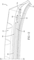
FIG. 2 is a close-up view of the belt package of the tire ofFIG. 1 . -
FIG. 1 illustrates a first embodiment of one half of apneumatic tire 10, suitable for use as a truck tire. Thetire 10 has atread 12 with a non-skid depth D. Thetire tread 12 may comprise a plurality of circumferentially continuous ribs, which may vary, but are shown for example asribs circumferential groove - The
tire 10 further comprises acasing 14 which includes two opposed sidewalls 16 which extend down from thetread 12 to the bead area. The casing of the tire may optionally include aninner liner 24 which is typically formed of halobutyl rubber which forms an air impervious barrier. Thetire casing 14 further includes one or moreradial plies 18 extending from the tread, down the sidewall to thetire bead 20. Preferably, theradial ply 18 is wrapped about or otherwise secured to eachannular bead 20. In the embodiment illustrated and not limited to same, there is only oneply 18 and it is wrapped around the bead in an inside out manner such that the ply ending 19 is located axially outward and radially outwards of the bead. Thebeads 20 may be any desired shape, but in this embodiment, it is shown as a hexagonal configuration with steel filaments. - The tire may further optionally include an
apex 21 which may be shaped like a triangle. The ply turnup in the bead area may be optionally reinforced with achipper 23 wrapped about thebead ply 18. - The
tire 10 further includes abelt package 50 which is located between the tread and the one ormore plies 18. The belt package may comprise one or more layers of reinforcement. Theply 18 and thebelt reinforcing structure 50 are made from cord reinforced elastomeric material, wherein the cords are typically steel wire or polyamide filaments and the elastomer preferably being rubber. - The
belt reinforcing package 50 may include an optionaltransitional belt 52 that is the radially innermost belt of thebelt package 50. Thetransition belt 52 has an axial belt width which preferably ranges from 60% to 90% of the tread arc width. Thetransition belt 52 preferably has an orientation that has an angle of from 45 to 70 degrees (preferably right). Thetransition belt 52 is preferably made of ultra tensile steel with a construction of 3+2x0.35 UT. -
Belt reinforcing structure 50 further includes a first and secondextensible working belt first working belt 54 is located radially inwards ofsecond working belt 56. Preferably,first working belt 54 has a belt width substantially equal to the tread arc width. Preferably, it is the widest belt of thebelt package 50. The breaker angle offirst working belt 54 is between 12 and 36 degrees, preferably with a right orientation, more preferably in the range of 14 to 18 degrees or more preferably 30 to 34 degrees. Thefirst working belt 54 is made of extensible or high elongation wire and has a % elongation at 10% of breaking load of greater than 0.2%, as measured from a cord taken from a cured tire. Preferably, the % elongation at the 10% of breaking load is greater than 0.4 %, more preferably greater than 0.8%, and most preferably greater than 1.2%. The first working belt construction is preferably formed of wire having a wire construction of 3x7x, 3x4x, 4x4x. Preferably, the wire has a construction of 4+3x, and more preferably, a wire construction of 4+3x0.35 UT. The EPI (ends per 2.54 cm) preferably ranges from 8 to 14. - The
second working belt 56 is located radially outward of the first working belt, and preferably has a width less than the width offirst working belt 54. Preferably, thesecond working belt 56 has a width less than the width ofbelt 54 by a step off, which preferably ranges from 10 to 20 mm. Theworking belt 56 has a breaker angle in a range of from 16 to 30 degrees, preferably with a left orientation, more preferably in the range of from 19 to 25 degrees. Thesecond working belt 56 is preferably made of extensible or high elongation wire, having the same construction with the same but opposite angular orientation as thefirst working belt 54. - The
belt structure 50 further comprises a relativelylow angle belt 58 which is preferably located between the working pair belts, 54, 56. The relativelylow angle belt 58 may also be located betweenbelts belt 56. The relativelylow angle belt 58 has reinforcements that are oriented circumferentially at 5 degrees or less, preferably at 0 degree or less than 1 degree. Thebelt 58 is preferably formed from spirally winding a rubberized strip of one or more cords. Preferably, the strip has 1-4 steel cords. Alternatively, thebelt 58 may be formed of a cut belt with the reinforcements oriented in the range of from 0 to 10 degrees from the circumferential direction, or more preferably in the range of from 0 to 5 degrees from the circumferential direction. The relativelylow angle belt 58 has a width sized to avoid compression in the shoulder area. The belt width of relativelylow angle belt 58 is preferably less than the belt width of the first and second working belts. The belt structure of the relativelylow angle belt 58 may be steel formed of a 3x7 construction, a 3x4 construction, or a 4x4 construction. More preferably, the belt structure of the relativelylow angle belt 58 is steel formed of a 3x7x0.22 construction, a 3x4x0.26 construction, or a 4x4x0.22 construction, and preferably formed of high tensile steel. The reinforcement cords of the relativelylow angle belt 58 are preferably extensible. For measurements taken from a bare cord taken from a cured tire, the % elongation at 10% of breaking load is greater than 0.2%, and preferably 0.4% or more, and more preferably 0.6% or more, and most preferably 0.8%. Alternatively, the relatively low angle belt may be formed of non-metal reinforcements such as aramid, carbon fiber, or polyketone or POK. - The belt structure may further include a
protector belt 62 that is the radially outermost belt. Thetop protector belt 62 has a width that is preferably in the range of from 80 to 85% of the width of the relativelylow angle belt 58. Preferably, thebelt 62 should have the same angle and orientation as the adjacent belt, 56. Theprotector belt 62 preferably has reinforcement cords made of high impact steel cord wherein the cord has full rubber penetration that helps in avoiding corrosion and enable excellent retreadability. It also provides high impact resistance as it exhibits more work to break because of its enhanced % elongation (> 5%) even after embedded in rubber. Preferably, the reinforcement cords of theprotector belt 62 have a cord construction of 5x, and more preferably, 5x0.35 or 5x0.38. - The reinforcement cords are preferably made of steel, and are preferably high impact cords (HI), with a very high energy absorption with energy/cord > 7.5 J/mm2 or > 10 J/mm2 using a Charpy Impact Tester and a Charpy Test (ASTM D6110-18) in a 2.54 cm strip with 10 EPI (ends per 2.54 cm).
- Maximum compressive stresses of such cords are above 350 MPa at maximum deformation at kinking of > 1.5%. Having a high-impact cord top protective belt helps in absorbing the shock created during an impact and relieves the stresses on the tread shoulder grooves.
- The aspect ratio of the
tire 12 described above may vary. The aspect ratio is preferably in the range of from 50 to 90. - The
tire 12 has a net to gross ratio in the range of from 70 to 90, more preferably in the range of from 74 to 86, more preferably from 78 to 84.
Claims (13)
- A pneumatic tire, the tire (10) comprising: a tread (12) and a belt reinforcement structure (50) located radially inward of the tread (12), the belt reinforcement structure (50) including a first working belt (54) comprising cords or wire and a second working belt (56) comprising cords or wire, wherein the angles of the cords of the wire in the first and second working belts (54, 56) range from +/- 12 degrees to +/-36 degrees with respect to the circumferential direction, wherein the belt reinforcement structure (50) further comprises a relatively low angle belt (58) comprising cords or wire angled at an angle of less than +/- 5 degrees with respect to the circumferential direction, and further including a protector belt (62) located radially outwards of the first and second working belt (54, 56), wherein the protector belt (62) comprises cords or wire having an energy absorption of more than 7.5 J/mm2.
- The tire of claim 1 wherein the relatively low angle belt (58) is located radially between the first and second working belt (54, 56).
- The tire of claim 1 or 2 wherein the first and second working belts (54, 56) comprise cords or wire having a % elongation at 10% of breaking load greater than 0.2%, alternatively greater than 0.4% or greater than 0.6%, when taken from cords or wire from a cured tire.
- The tire of at least one of the previous claims wherein the relatively low angle belt (58) comprises cords or wire having a % elongation at 10% of breaking load greater than 0.8 %, alternatively greater than 1.2%, when taken from wire from a cured tire.
- The tire of at least one of the previous claims wherein first working belt (54) has an axial width in a range of from 95% to 105% or of 100% to the tread arc width.
- The tire of at least one of the previous claims wherein first working belt (54) has an axial width greater than the axial width of the relatively low angle belt (58) and/or wherein the second working belt (56) has an axial width greater than the axial width of the relatively low angle belt (58).
- The tire of at least one of the previous claims wherein the first and second working belts (54, 56) each comprise a wire have a construction of 4+3x0.35 UT.
- The tire of at least one of the previous claims wherein the protector belt comprises cords or wire having a 5x construction, preferably a 5x0.35 or 5x0.38 construction.
- The tire of at least one of the previous claims wherein the first and second working belts (54, 56) comprise cords or wire having a 4+3x construction.
- The tire of at least one of the previous claims wherein the relatively low angle belt (58) comprises cords or wire having a 3x7 construction, a 4x4 construction, a 3x6 construction or a 3x4 construction.
- The tire of at least one of the previous claims wherein the protector belt (62) comprises cords or wire having an energy absorption of more than 10 J/mm2.
- The tire of at least one of the previous claims wherein the protector belt comprises steel cords.
- The tire of at least one of the previous claims wherein the tire is a truck tire.
Applications Claiming Priority (2)
| Application Number | Priority Date | Filing Date | Title |
|---|---|---|---|
| US202063072592P | 2020-08-31 | 2020-08-31 | |
| US17/346,381 US20220063336A1 (en) | 2020-08-31 | 2021-06-14 | Truck tire |
Publications (1)
| Publication Number | Publication Date |
|---|---|
| EP3960496A1 true EP3960496A1 (en) | 2022-03-02 |
Family
ID=79877199
Family Applications (1)
| Application Number | Title | Priority Date | Filing Date |
|---|---|---|---|
| EP21194156.2A Withdrawn EP3960496A1 (en) | 2020-08-31 | 2021-08-31 | Truck tire |
Country Status (4)
| Country | Link |
|---|---|
| US (1) | US20220063336A1 (en) |
| EP (1) | EP3960496A1 (en) |
| CN (1) | CN114103554A (en) |
| BR (1) | BR102021016729A2 (en) |
Cited By (2)
| Publication number | Priority date | Publication date | Assignee | Title |
|---|---|---|---|---|
| FR3160129A1 (en) * | 2024-03-18 | 2025-09-19 | Compagnie Generale Des Etablissements Michelin | Optimized tread and crown of civil engineering tire |
| EP4714674A3 (en) * | 2024-07-29 | 2026-07-01 | The Goodyear Tire & Rubber Company | TRUCK TIRES |
Citations (4)
| Publication number | Priority date | Publication date | Assignee | Title |
|---|---|---|---|---|
| WO1999006628A1 (en) * | 1997-07-29 | 1999-02-11 | N.V. Bekaert S.A. | Steel cord for protection plies of pneumatic tyres |
| EP2199104A2 (en) * | 2008-12-19 | 2010-06-23 | The Goodyear Tire & Rubber Company | Truck tire |
| US20130248073A1 (en) * | 2010-10-29 | 2013-09-26 | Continental Reifen Deutschland Gmbh | Pneumatic vehicle tire |
| WO2020035292A1 (en) * | 2018-08-16 | 2020-02-20 | Continental Reifen Deutschland Gmbh | Pneumatic tire for a vehicle |
Family Cites Families (10)
| Publication number | Priority date | Publication date | Assignee | Title |
|---|---|---|---|---|
| EP0342644B1 (en) * | 1988-05-20 | 1996-08-21 | TOYO TIRE & RUBBER CO., LTD . | Pneumatic tire |
| JP3005173B2 (en) * | 1995-03-07 | 2000-01-31 | 住友ゴム工業株式会社 | Radial tire for heavy duty vehicles |
| US5743975A (en) * | 1995-03-24 | 1998-04-28 | The Goodyear Tire & Rubber Company | Radial medium truck tire with organic polymer reinforced top belt or breaker |
| US5839264A (en) * | 1996-01-29 | 1998-11-24 | Tokyo Rope Manufacturing Co. | Steel cord for reinforcement of off-road tire |
| US6041839A (en) * | 1998-01-19 | 2000-03-28 | The Goodyear Tire & Rubber Company | Metallic 4+3 cord for the reinforcement of elastomers |
| US7404425B2 (en) * | 2002-04-24 | 2008-07-29 | The Goodyear Tire & Rubber Company | Belt package for super single truck tires |
| TR201907367T4 (en) * | 2010-08-06 | 2019-06-21 | Pirelli | Tire for wheels of heavy transport vehicles. |
| US8578990B2 (en) * | 2011-03-02 | 2013-11-12 | The Goodyear Tire & Rubber Company | Low aspect ratio super single truck tire |
| DE102015222447A1 (en) * | 2015-11-13 | 2017-05-18 | Continental Reifen Deutschland Gmbh | Vehicle tires |
| JP6805561B2 (en) * | 2016-06-13 | 2020-12-23 | 横浜ゴム株式会社 | Pneumatic tires |
-
2021
- 2021-06-14 US US17/346,381 patent/US20220063336A1/en not_active Abandoned
- 2021-08-24 BR BR102021016729-7A patent/BR102021016729A2/en not_active Application Discontinuation
- 2021-08-31 EP EP21194156.2A patent/EP3960496A1/en not_active Withdrawn
- 2021-08-31 CN CN202111011184.8A patent/CN114103554A/en active Pending
Patent Citations (4)
| Publication number | Priority date | Publication date | Assignee | Title |
|---|---|---|---|---|
| WO1999006628A1 (en) * | 1997-07-29 | 1999-02-11 | N.V. Bekaert S.A. | Steel cord for protection plies of pneumatic tyres |
| EP2199104A2 (en) * | 2008-12-19 | 2010-06-23 | The Goodyear Tire & Rubber Company | Truck tire |
| US20130248073A1 (en) * | 2010-10-29 | 2013-09-26 | Continental Reifen Deutschland Gmbh | Pneumatic vehicle tire |
| WO2020035292A1 (en) * | 2018-08-16 | 2020-02-20 | Continental Reifen Deutschland Gmbh | Pneumatic tire for a vehicle |
Cited By (3)
| Publication number | Priority date | Publication date | Assignee | Title |
|---|---|---|---|---|
| FR3160129A1 (en) * | 2024-03-18 | 2025-09-19 | Compagnie Generale Des Etablissements Michelin | Optimized tread and crown of civil engineering tire |
| WO2025195706A1 (en) * | 2024-03-18 | 2025-09-25 | Compagnie Generale Des Etablissements Michelin | Optimised tread and crown for a civil engineering tyre |
| EP4714674A3 (en) * | 2024-07-29 | 2026-07-01 | The Goodyear Tire & Rubber Company | TRUCK TIRES |
Also Published As
| Publication number | Publication date |
|---|---|
| US20220063336A1 (en) | 2022-03-03 |
| BR102021016729A2 (en) | 2022-07-26 |
| CN114103554A (en) | 2022-03-01 |
Similar Documents
| Publication | Publication Date | Title |
|---|---|---|
| EP2199104B1 (en) | Truck tire | |
| EP3838623B1 (en) | Truck tire | |
| CN113226798B (en) | Vehicle tires including reinforced structures | |
| EP4011645B1 (en) | Truck tire | |
| EP2423001B1 (en) | Pneumatic tire | |
| EP4144539B1 (en) | Pneumatic tire for use on truck | |
| US20220185034A1 (en) | Tire with improved bead structure | |
| US20220063336A1 (en) | Truck tire | |
| EP4011646B1 (en) | Truck tire | |
| EP3838621B1 (en) | Pneumatic tire | |
| EP4197815B1 (en) | Truck tire | |
| EP4197813B1 (en) | Truck tire | |
| EP4015253B1 (en) | Tire with improved bead structure | |
| EP4011647B1 (en) | Truck tire | |
| EP4197814B1 (en) | Truck tire | |
| EP3037284B1 (en) | Reduced weight aircraft tire | |
| EP4197812B1 (en) | Tire with reinforced sidewall layer | |
| BR102021024569A2 (en) | TRUCK TIRE | |
| BR102021024569B1 (en) | TIRE FOR USE ON TRUCKS |
Legal Events
| Date | Code | Title | Description |
|---|---|---|---|
| PUAI | Public reference made under article 153(3) epc to a published international application that has entered the european phase |
Free format text: ORIGINAL CODE: 0009012 |
|
| STAA | Information on the status of an ep patent application or granted ep patent |
Free format text: STATUS: THE APPLICATION HAS BEEN PUBLISHED |
|
| AK | Designated contracting states |
Kind code of ref document: A1 Designated state(s): AL AT BE BG CH CY CZ DE DK EE ES FI FR GB GR HR HU IE IS IT LI LT LU LV MC MK MT NL NO PL PT RO RS SE SI SK SM TR |
|
| RAP3 | Party data changed (applicant data changed or rights of an application transferred) |
Owner name: THE GOODYEAR TIRE & RUBBER COMPANY |
|
| STAA | Information on the status of an ep patent application or granted ep patent |
Free format text: STATUS: THE APPLICATION IS DEEMED TO BE WITHDRAWN |
|
| 18D | Application deemed to be withdrawn |
Effective date: 20220903 |