EP0342644B1 - Pneumatic tire - Google Patents
Pneumatic tire Download PDFInfo
- Publication number
- EP0342644B1 EP0342644B1 EP89108860A EP89108860A EP0342644B1 EP 0342644 B1 EP0342644 B1 EP 0342644B1 EP 89108860 A EP89108860 A EP 89108860A EP 89108860 A EP89108860 A EP 89108860A EP 0342644 B1 EP0342644 B1 EP 0342644B1
- Authority
- EP
- European Patent Office
- Prior art keywords
- wires
- steel cord
- cord
- steel
- tire
- Prior art date
- Legal status (The legal status is an assumption and is not a legal conclusion. Google has not performed a legal analysis and makes no representation as to the accuracy of the status listed.)
- Expired - Lifetime
Links
- 229910000831 Steel Inorganic materials 0.000 claims description 124
- 239000010959 steel Substances 0.000 claims description 124
- 239000000470 constituent Substances 0.000 claims description 43
- 238000007493 shaping process Methods 0.000 claims description 13
- 230000000052 comparative effect Effects 0.000 description 42
- 238000000926 separation method Methods 0.000 description 22
- 238000010276 construction Methods 0.000 description 21
- 238000012360 testing method Methods 0.000 description 8
- 238000005096 rolling process Methods 0.000 description 5
- 230000000694 effects Effects 0.000 description 4
- 238000004873 anchoring Methods 0.000 description 3
- 238000013016 damping Methods 0.000 description 3
- 230000003247 decreasing effect Effects 0.000 description 3
- 230000036961 partial effect Effects 0.000 description 3
- 230000035515 penetration Effects 0.000 description 3
- 230000000149 penetrating effect Effects 0.000 description 2
- 230000002829 reductive effect Effects 0.000 description 2
- 230000003014 reinforcing effect Effects 0.000 description 2
- 238000001612 separation test Methods 0.000 description 2
- 238000004073 vulcanization Methods 0.000 description 2
- XLYOFNOQVPJJNP-UHFFFAOYSA-N water Substances O XLYOFNOQVPJJNP-UHFFFAOYSA-N 0.000 description 2
- 208000027418 Wounds and injury Diseases 0.000 description 1
- 230000006378 damage Effects 0.000 description 1
- 238000009863 impact test Methods 0.000 description 1
- 230000002401 inhibitory effect Effects 0.000 description 1
- 208000014674 injury Diseases 0.000 description 1
- 239000000463 material Substances 0.000 description 1
- 238000000034 method Methods 0.000 description 1
- 239000000203 mixture Substances 0.000 description 1
- 238000012986 modification Methods 0.000 description 1
- 230000004048 modification Effects 0.000 description 1
Images

Classifications
-
- D—TEXTILES; PAPER
- D07—ROPES; CABLES OTHER THAN ELECTRIC
- D07B—ROPES OR CABLES IN GENERAL
- D07B1/00—Constructional features of ropes or cables
- D07B1/06—Ropes or cables built-up from metal wires, e.g. of section wires around a hemp core
- D07B1/0606—Reinforcing cords for rubber or plastic articles
- D07B1/062—Reinforcing cords for rubber or plastic articles the reinforcing cords being characterised by the strand configuration
-
- B—PERFORMING OPERATIONS; TRANSPORTING
- B60—VEHICLES IN GENERAL
- B60C—VEHICLE TYRES; TYRE INFLATION; TYRE CHANGING; CONNECTING VALVES TO INFLATABLE ELASTIC BODIES IN GENERAL; DEVICES OR ARRANGEMENTS RELATED TO TYRES
- B60C9/00—Reinforcements or ply arrangement of pneumatic tyres
- B60C9/0007—Reinforcements made of metallic elements, e.g. cords, yarns, filaments or fibres made from metal
-
- B—PERFORMING OPERATIONS; TRANSPORTING
- B60—VEHICLES IN GENERAL
- B60C—VEHICLE TYRES; TYRE INFLATION; TYRE CHANGING; CONNECTING VALVES TO INFLATABLE ELASTIC BODIES IN GENERAL; DEVICES OR ARRANGEMENTS RELATED TO TYRES
- B60C9/00—Reinforcements or ply arrangement of pneumatic tyres
- B60C9/18—Structure or arrangement of belts or breakers, crown-reinforcing or cushioning layers
- B60C9/20—Structure or arrangement of belts or breakers, crown-reinforcing or cushioning layers built-up from rubberised plies each having all cords arranged substantially parallel
- B60C9/2003—Structure or arrangement of belts or breakers, crown-reinforcing or cushioning layers built-up from rubberised plies each having all cords arranged substantially parallel characterised by the materials of the belt cords
- B60C9/2006—Structure or arrangement of belts or breakers, crown-reinforcing or cushioning layers built-up from rubberised plies each having all cords arranged substantially parallel characterised by the materials of the belt cords consisting of steel cord plies only
-
- D—TEXTILES; PAPER
- D07—ROPES; CABLES OTHER THAN ELECTRIC
- D07B—ROPES OR CABLES IN GENERAL
- D07B1/00—Constructional features of ropes or cables
- D07B1/06—Ropes or cables built-up from metal wires, e.g. of section wires around a hemp core
- D07B1/0606—Reinforcing cords for rubber or plastic articles
- D07B1/0646—Reinforcing cords for rubber or plastic articles comprising longitudinally preformed wires
-
- D—TEXTILES; PAPER
- D07—ROPES; CABLES OTHER THAN ELECTRIC
- D07B—ROPES OR CABLES IN GENERAL
- D07B2201/00—Ropes or cables
- D07B2201/20—Rope or cable components
- D07B2201/2015—Strands
- D07B2201/202—Strands characterised by a value or range of the dimension given
-
- D—TEXTILES; PAPER
- D07—ROPES; CABLES OTHER THAN ELECTRIC
- D07B—ROPES OR CABLES IN GENERAL
- D07B2201/00—Ropes or cables
- D07B2201/20—Rope or cable components
- D07B2201/2015—Strands
- D07B2201/2022—Strands coreless
-
- D—TEXTILES; PAPER
- D07—ROPES; CABLES OTHER THAN ELECTRIC
- D07B—ROPES OR CABLES IN GENERAL
- D07B2201/00—Ropes or cables
- D07B2201/20—Rope or cable components
- D07B2201/2015—Strands
- D07B2201/2023—Strands with core
-
- D—TEXTILES; PAPER
- D07—ROPES; CABLES OTHER THAN ELECTRIC
- D07B—ROPES OR CABLES IN GENERAL
- D07B2201/00—Ropes or cables
- D07B2201/20—Rope or cable components
- D07B2201/2015—Strands
- D07B2201/2024—Strands twisted
- D07B2201/2029—Open winding
-
- D—TEXTILES; PAPER
- D07—ROPES; CABLES OTHER THAN ELECTRIC
- D07B—ROPES OR CABLES IN GENERAL
- D07B2201/00—Ropes or cables
- D07B2201/20—Rope or cable components
- D07B2201/2015—Strands
- D07B2201/2036—Strands characterised by the use of different wires or filaments
- D07B2201/2037—Strands characterised by the use of different wires or filaments regarding the dimension of the wires or filaments
-
- Y—GENERAL TAGGING OF NEW TECHNOLOGICAL DEVELOPMENTS; GENERAL TAGGING OF CROSS-SECTIONAL TECHNOLOGIES SPANNING OVER SEVERAL SECTIONS OF THE IPC; TECHNICAL SUBJECTS COVERED BY FORMER USPC CROSS-REFERENCE ART COLLECTIONS [XRACs] AND DIGESTS
- Y10—TECHNICAL SUBJECTS COVERED BY FORMER USPC
- Y10S—TECHNICAL SUBJECTS COVERED BY FORMER USPC CROSS-REFERENCE ART COLLECTIONS [XRACs] AND DIGESTS
- Y10S57/00—Textiles: spinning, twisting, and twining
- Y10S57/902—Reinforcing or tyre cords
Definitions
- the present invention relates to a pneumatic tyre according to the preamble of claim 1, in which the rubber layer, i.e. said breaker or belt, between the carcass and tread has been reinforced with steel cords.
- carcass-protective reinforcing layers are interposed between the carcass and the tread.
- reinforcing layers called “belts” are interposed between the carcass and the tread and serves to brace up the carcass in the radial direction.
- the breaker or belt is often constructed in a plurality of layers. Particularly when the anti-cut property of a pneumatic tire must be increased, a plurality of steel cords capable of sufficient elongation are embedded at appropriate spacings in the outermost, i.e. adjacent to the tread, layer of the aforementioned breaker or belt.
- Figs. 9 and 10 are cross-section views showing the multi-strand steel cords heretofore used in the conventional pneumatic tire; thus, Fig. 9 represents the 4 x 4 x 0.23 construction, while Fig. 10 represents the 3 x 7 x 0.22 construction.
- a steel cord 10 is an assembly of four strands 16 twisted together and each strand 16, in turn, is an assembly of four constituent wires 12, each constituent wire 12 being a steel wire with a diameter of 0.23 mm.
- the twisting pitch of these constituent wires 12 is 3.5 mm and that of the strands 16 is 5.5 mm.
- the steel cord 10 illustrated in Fig. 10 is an assembly of three strands 16 twisted together.
- Each strand 16 is an assembly of seven constituent wires 12 and each of the wires 12 is a steel wire with a diameter of 0.22 mm.
- the twisting pitch of the wires 12 is 4.0 mm and that of the strands 16 is 7.5 mm.
- each of these steel cords 10 is a low-pitch multi-ply structure, it has a large elongation and is flexible, insuring a large impact-absorbing or damping capacity. Therefore, the conventional pneumatic tires utilizing these steel cords 10 had high anti-cut properties.
- the degree of so-called "twisting loss" of tenacity or strength is high and the strength of the respective wires 12 cannot be effectively utilized.
- an increased number of constituent wires 12 is required but the use of so many wires 12 adds to the overall weight of the steel cord 10.
- the steel cord 10 used heretofore is a flexible steel cord, the pneumatic tire is markedly deformed on the tread to create a large rolling resistance, thus detracting from milage.
- the wires 12 in the conventional construction are round in section and disposed in close contact and, for this reason, a closed air space 18 is created in the approximate center of the constituent wires. Therefore, in this steel cord 10, rubber is not easy to enter and fill the space 18. In other words, the resulting breaker or belt will have the space 18 unfilled with rubber. If the tread of the tire is damaged and consequently water finds its way from the site of injury into the space 18, the invading water migrates within the space 18 along the length of steel cord 10 and, also, remains entrapped therein. Consequently the steel cord 10 becomes rusted with time, detracting from the strength of bond to the rubber. If this decrease in bond strength progresses, there occurs the trouble known as "separation".
- Fig. 11 is a cross-section view showing the steel cord used in the pneumatic tire according to this arrangement.
- This steel cord 10 is a single-strand cord of 1 x 5 x 0.38 construction. Thus, it is an assembly of five wires 12 each having a diameter of 0.38 mm. The twisting pitch is 6.5 mm and the elongation at break of the cord is 6.5%.
- this steel cord 10 has an elongation at break of not less than 4% and, therefore, offers an anti-cut performance comparable to that of a multi-strand steel cord. Furthermore, because of the very single-strand construction, the rate of wire tenacity utilization is high. This means that the desired tire strength is attainable even if the overall weight of the tire cord is decreased, and that accordingly a lightweight pneumatic tire can be implemented. Moreover, because of the adequate flexural hardness of the steel cord 10, the rigidity of the pneumatic tire is enhanced. Therefore, the deformation and, hence, rolling resistance of the tire are reduced, thus contributing to milage.
- the wires 12 are identical in diameter and shaping rate so that all the wires 12 form one common circumcircle 22. Therefore, though the incidence of separation is inhibited, the effect of anchoring the steel cord in the rubber constituting the breaker or belt is so small that the separation once started tends to grow easily.
- EP-A-0 264 071 discloses a pneumatic type with the features set out in the pre-characterizing part of claim 1.
- this invention has as its object to provide a pneumatic tire in which the strength or tenacity of material wires is effectively exploited, while maintaining the anti-cut property of the tire at a level comparable to that of the conventional tire, to thereby improve the rigidity of the tire while the incidence and growth of separation having been successfully inhibited.
- this invention relates to a pneumatic tire characterized in that, of the breaker or belt consisting of a plurality of rubber layers which is disposed between the carcass and the tread, at least the outermost layer has been reinforced with a plurality of steel cords, each of which is a single-strand cord with an elongation at break of at least 4 percent, with the constituent wires of the cord forming no single common circumcircle.
- the steel cord made up of constituent wires forming no single common tangent circle that is to say a steel cord in which the curve circumscribing the cross-sections of all of its constituent wires is not a true circle, can be implemented by varying the shaping rate of some of its constituent wires or varying the diameter of some of its constituent wires from that of the other wires.
- the shaping rate of a wire is understood to be the ratio of a circumcircle defined by this wire to a concentric circumcircle of a cord having all constituent wires hermetically contacting neighboring wires.
- the steel cord Since, in the pneumatic tire of this invention, the steel cord has a high elongation at break of not less than 4%, it has an anti-cut property equivalent to that of a multi-strand cord. Moreover, as the steel cord is a single-strand cord, the rate of wire tenacity utilization is improved. Therefore, the desired cord strength can be realized even if the overall weight of the steel cord is decreased, thus enabling the provision of a lightweight pneumatic tire. Furthermore, in accordance with this invention, a high tire rigidity is assured by the adequate flexural hardness of the steel cord. Therefore, the deformation and, hence, rolling resistance of the tire are decreased to insure a greater milage.
- the space defined by the constituent wires is locally exposed to the atmosphere to allow the entry of rubber, the incidence of separation is successfully inhibited.
- the steel cord of this invention has surface irregularities. Therefore, the bonding interface between the steel cord and rubber is discrete and accordingly the distribution of the shear strain produced between the steel cord and rubber during driving is also dispersed. That is to say, even if a minor separation occurs, its propagation or growth is inhibited.
- the pneumatic tire of this invention is so designed that, with respect to a large majority of steel cords, the direction of maximum offset span of circumscribed curves is substantially coincidental with the width direction of the outermost layer. Since, in this pneumatic tire, the interval between steel cord ends is small, the resistance to nail penetration has been improved.
- the substantial alignment of the directions of the steel cord corcumscribed curves can be achieved, for example by orienting the steel cords by means of grooves formed in a calender and apply the rubber to the cords.
- a steel cord 10 is a steel cord of the 1 x 5 x 0.38 single-strand construction, that is to say, a twisted assembly of five constituent steel wires, each having a diameter of 0.38 mm.
- one wire 13 has a higher shaping rate than the other four wires 12. Therefore, though the center of the circumscribed circle 23 of the wire 13 coincides with the center of the steel cord 10, its radius is larger by d than that of the common circumcircle of the other constituent wires 12. This radius differential d is 0.06 mm.
- the maximum offset span is represented by the symbol D.
- the twisting pitch of constituent wires 12 and 13 is 6.5 mm and the elongation at break of the steel cord 10 is 6.7%. Moreover, local gaps with a width of at least about 0.02 mm are formed between the constituent wires along the length of the cord, so that the space 14 defined by the wires is exposed to the atmosphere. Therefore, in the vulcanization of a radial-ply tire having a belt in which this steel cord 10 is embedded, the rubber may enter the space 14 through said gaps between the constituent wires to fill the space 14.
- Figs. 2 through 5 are cross-section views showing modifications of the steel cord 10.
- these steel cords 10 are invariably similar to the steel cord 10 illustrated in Fig. 1.
- the shaping rate of one constituent wire 13 is smaller than that of the other four wires 12.
- the shaping rate of one constituent wire 13a is larger than that of three constituent wires 12, with the shaping rate of the remaining wire 13b being still larger than that of said wire 13a.
- a steel cord 10 consisting of component wires devoid of a common circumcircle.
- a circumscribing curve which is not a true circle with respect to the cross-sections of all the constituent wires can be realized.
- a steel cord having a circumcircle may be flattened by means of a roller.
- a similar steel cord 10 can also be implemented by varying the diameter of one or more constituent wires from that of the remaining wires.
- the shaping rate is the same for the five constituent wires but the diameter of one constituent wire 13 is larger than that of the other four wires 12.
- one constituent wire 13 is finer than the other four constituent wires 12.
- Fig. 6 is a partial sectional view showing a radial-ply tire having a belt whose outermost layer has steel cords 10 embodied. In this view, however, the steel cords 10 are not shown.
- the radial-ply tire 2 illustrated in Fig. 6 has a size of 11 R 22.5 and includes four belts 8a, 8b, 8c and 8d between a carcass 4 and a tread 6.
- Embedded in the three belts 8a, 8b and 8c on the carcass side are steel cords of the 3 x 0.20 + 6 x 0.35 construction. This means that each of these steel cords consists of three steel wires with a diameter of 0.20 mm and six steel wires with a diameter of 0.35 mm. The density of cords is 12 cords per 2.5 cm.
- These three belts 8a, 8b and 8c brace the polyester-ply carcass 4 in the radial direction.
- the belt 8d is prepared by orienting steel cords 10 in parallel, applying a rubber composition thereto from both sides to form a rubber layer 11 and vulcanizing the rubber layer 11.
- the density of cords is 12 cords per 2.5 cm. It should be understood that, for insuring a better adhesion to the rubber, all the steel wires are brass-plated.
- the three belts 8a, 8b and 8c function as hoops for the carcass 4.
- the outermost layer belt 8d contributes to the anti-cut property of the radial-ply tire 2 as will be explained hereinafter.
- the characteristics of the steel cord 10 are set forth in Table 1 and the characteristics of the outermost layer belt 8d and those of the tire itself are set forth in Table 2, all as Example 1.
- Comparative Example 1 represents to steel cords of the single-strand construction illustrated in Fig. 11; Comparative Example 2 represents those of the multi-strand construction illustrated in Fig. 9; Comparative Example 3 represents those of the multi-strand construction illustrated in Fig. 10; and Comparative Example 4 represents those of the single-strand construction illustrated in Fig. 12.
- the pneumatic tires according to these respective comparative examples are 11 R 22.5 radial-ply tires comparable to the radial-ply tire of Example 1 and the carcass 4 and the three belts 8a, 8b and 8C are the same as those of Example 1.
- Embedded in the outermost belts 8d are the above-mentioned steel cords specific to the respective comparative examples.
- the steel cord 10 according to Example 1 has a small twisting pitch of 6.5 mm and an elongation at break of 6.7%, thus being comparable to the multi-strand cords of Comparative Examples 2 and 3 in terms of elongation property. Furthermore, as shown in Table 1, a Sharpy impact test revealed that the damping property of the tire of Example 1 is comparable to that of the tires of Comparative Examples 2 and 3. These data suggested that the pneumatic tire of Example 1 insures an anti-cut performance equivalent to that of the tire implemented with steel cords of the multi-strand construction.
- the tire of Example 1 showed an anti-cut performance comparable to that of the pneumatic tires according to Comparative Examples 2 and 3.
- the determination of anti-cut property was performed in the following manner. Thus, if a cut penetrating through the tread 6 and reaching the belt 8d occurs, cutting of the steel cord 10 embedded in the belt may or may not occur depending on cases.
- the cord cut rates shown in Table 2 each is the number of cord cuts relative to the total number of cuts.
- the wire tenacity utilization rate of the steel cord of Example 1 is not so high as that of Comparative Example 4 but is higher than those of Comparative Examples 2 and 3. Therefore, the overall cord weight necessary for achieving a given cord strength is less than that in Comparative Examples 2 and 3, thus contributing to reduced tire weight. Moreover, because of the adequate flexural hardness of the steel cord 10 in Example 1, the tire rigidity is higher and the rolling resistance is smaller as compared with Comparative Examples 2 and 3. Therefore, a better milage can be expected with the pneumatic tire of Example 1.
- Example 1 was comparable to Comparative Example 1.
- Steel cords 10 were manufactured according to the respective examples of the invention illustrated in Figs. 1, 4 and 5 and subjected to the dynamic separation test. The results of this test are shown in Table 3, as Example 2, Example 3 and Example 4, respectively. It should be understood, however, that the steel cord 10 of Example 2 was a twisted assembly of five constituent wires with a uniform diameter of 0.38 mm, with one of the wires, 13, having a larger shaping rate than that of the other four wires 12. The diameter differential d was 0.09 mm. In the steel cord 10 according to Example 3, four constituent wires 12 had a diameter of 0.38 mm, while the remaining wire 13 had a diameter of 0.45 mm. The radius differential d was 0.07 mm.
- Example 4 the diameter of four constituent wires was 0.38 mm and that of the remaining one wire 13 was 0.30 mm. The radius differential was 0.08 mm. In all the examples, the twisting pitch of steel cord 10 was 6.5 mm and the elongation at break of the cord was comparable to that of Example 1.
- Comparative Example 5 represents the single-strand steel cord illustrated in Fig. 11 and Comparative Example 6 represents the single-strand steel cord illustrated in Fig. 12.
- the degree of irregularity of steel cord 10 that is to say the diameter differential d , is preferably 5 to 50 percent of the diameter of the steel cord 10. If the value of d is less than 5%, no significant anchoring effect may be expected, while any value of d in excess of 50% results in an excess size of steel cord 10, which reduces the clearance from the adjacent cord and, hence, accelerates the propagation of separation.
- FIG. 7 is a partial section view showing, on exaggerated scale, this outermost layer belt 8d.
- Each steel cord 10 is embedded in such a manner that the direction of maximum offset span of its circumscribing curve is substantially coincidental with the width direction of the outermost layer belt 8d.
- This alignment of the direction of maximum offset span with the width direction of the outermost belt 8d can be accomplished, for example, by orienting the steel cords 10 by means of grooves provided in a calender and topping the cords 10 with rubber from both sides to provide a rubber layer 11. This rubber layer 11 is further vulcanized.
- the steel cord 10 may, for example, have a maximum offset span D of 1.38 mm and a minimum offset span of 1.05 mm. In the case of this belt 8d, too, the cord density is 12 cords per 2.5 cm and the interval of cord ends may be uniform at 0.73 mm.
- Table 4 the characteristics of the steel cord 10, outermost layer belt 8d and tire are shown in Table 4, as Example 4. In the table, characteristics of two Comparative Examples are also shown. In Comparative Example 7, as in Example 5, the steel cord 10 having the construction illustrated in Fig. 4 was employed. However, as shown in the sectional view of the outermost layer belt 8e in Fig. 8, the direction of maximum offset span of the circumscribed curve is random.
- the interval of cord ends is distributed over a broad range of 0.73 to 1.07 mm.
- the steel cord of Fig. 11 wherein the constituent wires have a common circumscribed circle was used in the outermost layer belt.
- the pneumatic tires according to these Comparative Examples are also radial-ply tires sized 285/75 R 24.5 as in Example 5 and the carcass 4 and inner three belts 8a, 8b and 8c were the same as those in Example 5.
- the outermost belts of Examples 5 and Comparative Example 7 are superior to the outermost belt of Comparative Example 8 in the anchor effect for steel cords with respect to the rubber consisting the belts and in the entry of rubber. Therefore, the incidence and growth of separation are better inhibited.
- the same table shows the number of belt penetrations by nails in the 100,000 kilometer driving trial. In the case of Example 5, there was no penetration at all.
- the pneumatic tire according to Example 5 not only has an anti-cut performance comparable to that of the tire representing the multi-strand steel cord structure but shows an improved wire tenacity utilization rate as compared with the multi-strand construction.
- the number of belts in which steel cords 10 are embedded may be appropriately increased as required.
- the two belts 8c and 8d on the tread size may have steel cords 10 embedded.
- Table 1 Example 1 Comparative Example 1 Comparative Example 2 Comparative Example 3 Comparative Example 4 Steel cord Construction Single-strand 1 x 5 x 0.38 (Fig. 1) Single-strand 1 x 5 x 0.38 (Fig. 11) Multi-strand 4 x 4 x 0.23 (Fig. 9) Multi-strand 3 x 7 x 0.22 (Fig. 10) Single-strand 1 x 5 x 0.38 (Fig.
Landscapes
- Engineering & Computer Science (AREA)
- Mechanical Engineering (AREA)
- Ropes Or Cables (AREA)
- Tires In General (AREA)
Description
- The present invention relates to a pneumatic tyre according to the preamble of claim 1, in which the rubber layer, i.e. said breaker or belt, between the carcass and tread has been reinforced with steel cords.
- In the bias-ply automotive pneumatic tire, carcass-protective reinforcing layers, known as breakers, are interposed between the carcass and the tread. In the radial-ply tire, reinforcing layers called "belts" are interposed between the carcass and the tread and serves to brace up the carcass in the radial direction. In such a pneumatic tire, it is common practice to increase the service life of the tire by embedding steel cords in the breakers or belts.
- The breaker or belt is often constructed in a plurality of layers. Particularly when the anti-cut property of a pneumatic tire must be increased, a plurality of steel cords capable of sufficient elongation are embedded at appropriate spacings in the outermost, i.e. adjacent to the tread, layer of the aforementioned breaker or belt.
- In the conventional steel cord, it is common practice, as explained below, to implement a large elongation value by adopting a multi-strand structure.
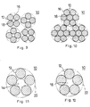
- Figs. 9 and 10 are cross-section views showing the multi-strand steel cords heretofore used in the conventional pneumatic tire; thus, Fig. 9 represents the 4 x 4 x 0.23 construction, while Fig. 10 represents the 3 x 7 x 0.22 construction.
- Referring to Fig. 9, a
steel cord 10 is an assembly of fourstrands 16 twisted together and eachstrand 16, in turn, is an assembly of fourconstituent wires 12, eachconstituent wire 12 being a steel wire with a diameter of 0.23 mm. The twisting pitch of theseconstituent wires 12 is 3.5 mm and that of thestrands 16 is 5.5 mm. - The
steel cord 10 illustrated in Fig. 10 is an assembly of threestrands 16 twisted together. Eachstrand 16 is an assembly of sevenconstituent wires 12 and each of thewires 12 is a steel wire with a diameter of 0.22 mm. The twisting pitch of thewires 12 is 4.0 mm and that of thestrands 16 is 7.5 mm. - Since each of these
steel cords 10 is a low-pitch multi-ply structure, it has a large elongation and is flexible, insuring a large impact-absorbing or damping capacity. Therefore, the conventional pneumatic tires utilizing thesesteel cords 10 had high anti-cut properties. - The conventional tires employing steel cords of the above-described constructions present the following problems, however.
- Thus, in the conventional
multi-strand steel cords 10, the degree of so-called "twisting loss" of tenacity or strength is high and the strength of therespective wires 12 cannot be effectively utilized. In order to obtain a desired strength forsteel cord 10, an increased number ofconstituent wires 12 is required but the use of somany wires 12 adds to the overall weight of thesteel cord 10. Moreover, since thesteel cord 10 used heretofore is a flexible steel cord, the pneumatic tire is markedly deformed on the tread to create a large rolling resistance, thus detracting from milage. - Furthermore, as will be apparent from Figs. 9 and 10, the
wires 12 in the conventional construction are round in section and disposed in close contact and, for this reason, a closedair space 18 is created in the approximate center of the constituent wires. Therefore, in thissteel cord 10, rubber is not easy to enter and fill thespace 18. In other words, the resulting breaker or belt will have thespace 18 unfilled with rubber. If the tread of the tire is damaged and consequently water finds its way from the site of injury into thespace 18, the invading water migrates within thespace 18 along the length ofsteel cord 10 and, also, remains entrapped therein. Consequently thesteel cord 10 becomes rusted with time, detracting from the strength of bond to the rubber. If this decrease in bond strength progresses, there occurs the trouble known as "separation". - Therefore, the present applicant previously proposed, in the Japanese Patent Application JP-A-1-250483, "a pneumatic tire in which the rubber layer between the carcass and tread has been reinforced with single-strand steel cords with an elongation at break of not less than 4%".
- Fig. 11 is a cross-section view showing the steel cord used in the pneumatic tire according to this arrangement.
- This
steel cord 10 is a single-strand cord of 1 x 5 x 0.38 construction. Thus, it is an assembly of fivewires 12 each having a diameter of 0.38 mm. The twisting pitch is 6.5 mm and the elongation at break of the cord is 6.5%. - Despite being a single-strand cord, this
steel cord 10 has an elongation at break of not less than 4% and, therefore, offers an anti-cut performance comparable to that of a multi-strand steel cord. Furthermore, because of the very single-strand construction, the rate of wire tenacity utilization is high. This means that the desired tire strength is attainable even if the overall weight of the tire cord is decreased, and that accordingly a lightweight pneumatic tire can be implemented. Moreover, because of the adequate flexural hardness of thesteel cord 10, the rigidity of the pneumatic tire is enhanced. Therefore, the deformation and, hence, rolling resistance of the tire are reduced, thus contributing to milage. Furthermore, since clearances are created betweenconstituent wires 12 at intervals along the length of the steel cord, thespace 14 enclosed by thewires 12 is exposed to the atmosphere. Therefore, in the vulcanization of the pneumatic tire having a breaker or belt in which thissteel cord 10 has been embedded, the rubber finds its way readily into thespace 14 and as the space is thus filled with the rubber, the incidence of "separation" is virtually inhibited. - However, even in the case of a steel cord having the same 1 x 5 x 0.38 construction, its anti-cut property is poor when its twisting pitch is as large as 18.0 mm and its elongation is as small as, for example, 2.5%. In addition, as illustrated in Fig. 12, a closed
space 18 is formed by and among thewires 12. Therefore, in the result of arresting the entry of rubber into thespace 18, this cord is equivalent to the aforementioned multi-strand cord. - In the pneumatic tire disclosed in the patent application mentioned above, the
wires 12 are identical in diameter and shaping rate so that all thewires 12 form onecommon circumcircle 22. Therefore, though the incidence of separation is inhibited, the effect of anchoring the steel cord in the rubber constituting the breaker or belt is so small that the separation once started tends to grow easily. - EP-A-0 264 071 discloses a pneumatic type with the features set out in the pre-characterizing part of claim 1.
- Having been accomplished in view of the above situation, this invention has as its object to provide a pneumatic tire in which the strength or tenacity of material wires is effectively exploited, while maintaining the anti-cut property of the tire at a level comparable to that of the conventional tire, to thereby improve the rigidity of the tire while the incidence and growth of separation having been successfully inhibited.
- These objects are met by the features of claim 1.
- More specifically, this invention relates to a pneumatic tire characterized in that, of the breaker or belt consisting of a plurality of rubber layers which is disposed between the carcass and the tread, at least the outermost layer has been reinforced with a plurality of steel cords, each of which is a single-strand cord with an elongation at break of at least 4 percent, with the constituent wires of the cord forming no single common circumcircle.
- The steel cord made up of constituent wires forming no single common tangent circle, that is to say a steel cord in which the curve circumscribing the cross-sections of all of its constituent wires is not a true circle, can be implemented by varying the shaping rate of some of its constituent wires or varying the diameter of some of its constituent wires from that of the other wires.
- The shaping rate of a wire is understood to be the ratio of a circumcircle defined by this wire to a concentric circumcircle of a cord having all constituent wires hermetically contacting neighboring wires.
- Since, in the pneumatic tire of this invention, the steel cord has a high elongation at break of not less than 4%, it has an anti-cut property equivalent to that of a multi-strand cord. Moreover, as the steel cord is a single-strand cord, the rate of wire tenacity utilization is improved. Therefore, the desired cord strength can be realized even if the overall weight of the steel cord is decreased, thus enabling the provision of a lightweight pneumatic tire. Furthermore, in accordance with this invention, a high tire rigidity is assured by the adequate flexural hardness of the steel cord. Therefore, the deformation and, hence, rolling resistance of the tire are decreased to insure a greater milage. Furthermore, since the space defined by the constituent wires is locally exposed to the atmosphere to allow the entry of rubber, the incidence of separation is successfully inhibited. Moreover, as the constituent wires have no single common circumscribed circle, the steel cord of this invention has surface irregularities. Therefore, the bonding interface between the steel cord and rubber is discrete and accordingly the distribution of the shear strain produced between the steel cord and rubber during driving is also dispersed. That is to say, even if a minor separation occurs, its propagation or growth is inhibited.
- However, even with this steel cord, if the direction of maximum offset span of the curve circumscribing the cross-sections of the constituent wires is random for the respective steel cords, it will happen that the direction of maximum offset span of some circumscribed curves coincide with the thickness direction of the outermost layer so that the interval between the steel cord ends may be increased to a greater extent than in the conventional tire to thereby increase the chances of entrapping of nails and other foreign bodies.
- To overcome the above disadvantage, the pneumatic tire of this invention is so designed that, with respect to a large majority of steel cords, the direction of maximum offset span of circumscribed curves is substantially coincidental with the width direction of the outermost layer. Since, in this pneumatic tire, the interval between steel cord ends is small, the resistance to nail penetration has been improved. The substantial alignment of the directions of the steel cord corcumscribed curves can be achieved, for example by orienting the steel cords by means of grooves formed in a calender and apply the rubber to the cords.
-
- Fig. 1 is a cross-section view showing a pneumatic tire steel cord embodying the principle of this invention;
- Fig. 2 is a cross-section view showing another pneumatic tire steel cord embodying the principle of this invention;
- Fig. 3 is a cross-section view showing a still another pneumatic tire steel cord embodying the principle of this invention;
- Fig. 4 is a cross-section view showing another yet pneumatic tire steel cord embodying the principle of this invention;
- Fig. 5 is a cross-section view showing a further different pneumatic tire steel cord embodying the principle of this invention;
- Fig. 6 is a partial section view showing a pneumatic tire embodying the principle of this invention, in which the outermost layer of rubber between the carcass and tread has been reinforced with the steel cord illustrated in Fig. 4;
- Fig. 7 is an exaggerated sectional view showing an example of the outermost rubber layer in Fig. 6;
- Fig. 8 is an exaggerated sectional view showing a comparative example in regard to the outermost rubber layer shown in Fig. 7;
- Fig. 9 is a cross-section view showing the conventional steel cord;
- Fig. 10 is a cross-section view showing another conventional steel cord;
- Fig. 11 is a cross-section view showing the pneumatic tire steel cord according to the prior art; and
- Fig. 12 is a cross-section view showing a comparative example with respective to the tire cord illustrated in Fig. 11.
- This invention is described in detail below, reference being had to the accompanying drawings.
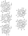
- Referring to Fig. 1 which is a cross-section view showing a pneumatic tire steel cord embodying the principle of this invention, a
steel cord 10 is a steel cord of the 1 x 5 x 0.38 single-strand construction, that is to say, a twisted assembly of five constituent steel wires, each having a diameter of 0.38 mm. Of the five constituent steel wires of the same diameter, onewire 13 has a higher shaping rate than the other fourwires 12. Therefore, though the center of the circumscribedcircle 23 of thewire 13 coincides with the center of thesteel cord 10, its radius is larger by d than that of the common circumcircle of the otherconstituent wires 12. This radius differential d is 0.06 mm. The maximum offset span is represented by the symbol D. The twisting pitch ofconstituent wires steel cord 10 is 6.7%. Moreover, local gaps with a width of at least about 0.02 mm are formed between the constituent wires along the length of the cord, so that thespace 14 defined by the wires is exposed to the atmosphere. Therefore, in the vulcanization of a radial-ply tire having a belt in which thissteel cord 10 is embedded, the rubber may enter thespace 14 through said gaps between the constituent wires to fill thespace 14. - Figs. 2 through 5 are cross-section views showing modifications of the
steel cord 10. - In the aspect of being a single-strand construction consisting of 5 constituent wires, these
steel cords 10 are invariably similar to thesteel cord 10 illustrated in Fig. 1. - However, in the
steel cord 10 shown in Fig. 2, the shaping rate of oneconstituent wire 13 is smaller than that of the other fourwires 12. In thesteel cord 10 shown in Fig. 3, the shaping rate of oneconstituent wire 13a is larger than that of threeconstituent wires 12, with the shaping rate of the remainingwire 13b being still larger than that of saidwire 13a. Thus, by varying the shaping rate of one or more constituent wires from that of the remaining wires, there can be implemented asteel cord 10 consisting of component wires devoid of a common circumcircle. Thus, a circumscribing curve which is not a true circle with respect to the cross-sections of all the constituent wires can be realized. As an alternative method, a steel cord having a circumcircle may be flattened by means of a roller. - A
similar steel cord 10 can also be implemented by varying the diameter of one or more constituent wires from that of the remaining wires. In thesteel cord 10 illustrated in Fig. 4, the shaping rate is the same for the five constituent wires but the diameter of oneconstituent wire 13 is larger than that of the other fourwires 12. In thesteel cord 10 illustrated in Fig. 5, oneconstituent wire 13 is finer than the other fourconstituent wires 12. - In all of these versions illustrated and described, the aspect of the
interwire space 14 being exposed is the same as in the embodiment shown in Fig. 1. - Fig. 6 is a partial sectional view showing a radial-ply tire having a belt whose outermost layer has
steel cords 10 embodied. In this view, however, thesteel cords 10 are not shown. - The radial-
ply tire 2 illustrated in Fig. 6 has a size of 11 R 22.5 and includes fourbelts carcass 4 and atread 6. Embedded in the threebelts belts ply carcass 4 in the radial direction. Embedded in theoutermost layer belt 8d are thesteel cords 10 illustrated in Fig. 1. Thus, thebelt 8d is prepared by orientingsteel cords 10 in parallel, applying a rubber composition thereto from both sides to form arubber layer 11 and vulcanizing therubber layer 11. In thisbelt 8d, too, the density of cords is 12 cords per 2.5 cm. It should be understood that, for insuring a better adhesion to the rubber, all the steel wires are brass-plated. - The three
belts carcass 4. Theoutermost layer belt 8d contributes to the anti-cut property of the radial-ply tire 2 as will be explained hereinafter. - Referring to the radial-
ply tire 2 according to the above embodiment of this invention, the characteristics of thesteel cord 10 are set forth in Table 1 and the characteristics of theoutermost layer belt 8d and those of the tire itself are set forth in Table 2, all as Example 1. - The two tables mentioned above show the characteristics of four comparative examples as well. Comparative Example 1 represents to steel cords of the single-strand construction illustrated in Fig. 11; Comparative Example 2 represents those of the multi-strand construction illustrated in Fig. 9; Comparative Example 3 represents those of the multi-strand construction illustrated in Fig. 10; and Comparative Example 4 represents those of the single-strand construction illustrated in Fig. 12. The pneumatic tires according to these respective comparative examples are 11 R 22.5 radial-ply tires comparable to the radial-ply tire of Example 1 and the
carcass 4 and the threebelts outermost belts 8d are the above-mentioned steel cords specific to the respective comparative examples. - Despite being of the single-strand construction, the
steel cord 10 according to Example 1 has a small twisting pitch of 6.5 mm and an elongation at break of 6.7%, thus being comparable to the multi-strand cords of Comparative Examples 2 and 3 in terms of elongation property. Furthermore, as shown in Table 1, a Sharpy impact test revealed that the damping property of the tire of Example 1 is comparable to that of the tires of Comparative Examples 2 and 3. These data suggested that the pneumatic tire of Example 1 insures an anti-cut performance equivalent to that of the tire implemented with steel cords of the multi-strand construction. Actually, in the 30,000 kilometer rugged terrain field trial performed on a quarry ground using large-sized dumping cars equipped with the respective raidal-ply tires, the tire of Example 1 showed an anti-cut performance comparable to that of the pneumatic tires according to Comparative Examples 2 and 3. The determination of anti-cut property was performed in the following manner. Thus, if a cut penetrating through thetread 6 and reaching thebelt 8d occurs, cutting of thesteel cord 10 embedded in the belt may or may not occur depending on cases. The cord cut rates shown in Table 2 each is the number of cord cuts relative to the total number of cuts. It should be noted that as to thesteel cord 10 according to Comparative Example 4, because its twisting pitch is as large as 18.0 mm, just as in the conventional tire, its elongation is as small as about 2.5% and, therefore, this tire has a poor anti-cut property. - Furthermore, the wire tenacity utilization rate of the steel cord of Example 1 is not so high as that of Comparative Example 4 but is higher than those of Comparative Examples 2 and 3. Therefore, the overall cord weight necessary for achieving a given cord strength is less than that in Comparative Examples 2 and 3, thus contributing to reduced tire weight. Moreover, because of the adequate flexural hardness of the
steel cord 10 in Example 1, the tire rigidity is higher and the rolling resistance is smaller as compared with Comparative Examples 2 and 3. Therefore, a better milage can be expected with the pneumatic tire of Example 1. - Furthermore, because rubber finds its way efficiently into the
space 14 defined by theconstituent wires 12, the pneumatic tire of Example 1 showed no separation ofbelt 8d in sharp contrast with Comparative Examples 2 to 4. In this respect, Example 1 was comparable to Comparative Example 1. - The results of the dynamic separation test with the respective tires are also shown in Table 2. For use as specimens for this test, two outermost layer belts were laid up and vulcanized and these layers were preliminarily separated over a width of 2.5 cm. The separation was caused to proceed at 100°C under the test settings of an amplitude of 3 mm and 330RPM and the time till growth of separation to a length of 10 cm was taken as the dynamic separation life. In the table, the relative lives taking the dynamic separation life for Comparative Example 4 as 100. The dynamic separation coverage value is the rubber attachment rate for the
steel cord 10 as found in the observation of the 10 cm long portion undergoing separation. The data generated by this test indicated that, in the case of Example 1, the effect of anchoring thesteel cord 10 in the rubber constituting thebelt 8d is higher, thus inhibiting the progress of separation, as compared with Comparative Example 1. -
Steel cords 10 were manufactured according to the respective examples of the invention illustrated in Figs. 1, 4 and 5 and subjected to the dynamic separation test. The results of this test are shown in Table 3, as Example 2, Example 3 and Example 4, respectively. It should be understood, however, that thesteel cord 10 of Example 2 was a twisted assembly of five constituent wires with a uniform diameter of 0.38 mm, with one of the wires, 13, having a larger shaping rate than that of the other fourwires 12. The diameter differential d was 0.09 mm. In thesteel cord 10 according to Example 3, fourconstituent wires 12 had a diameter of 0.38 mm, while the remainingwire 13 had a diameter of 0.45 mm. The radius differential d was 0.07 mm. In Example 4, the diameter of four constituent wires was 0.38 mm and that of the remaining onewire 13 was 0.30 mm. The radius differential was 0.08 mm. In all the examples, the twisting pitch ofsteel cord 10 was 6.5 mm and the elongation at break of the cord was comparable to that of Example 1. - The table also shows the characteristics of two comparative examples. Comparative Example 5 represents the single-strand steel cord illustrated in Fig. 11 and Comparative Example 6 represents the single-strand steel cord illustrated in Fig. 12.
- These test results show that like the steel cord of Example 2 which was constructed by varying the shaping rate, the cords of Example 3 and 4, which were constructed by varying the wire diameter, are also useful.
- In order that the elongation at break of
steel cord 10 may be 4% or more, the relation of twisting pitch P and cord diameter D is set at
steel cord 10, that is to say the diameter differential d, is preferably 5 to 50 percent of the diameter of thesteel cord 10. If the value of d is less than 5%, no significant anchoring effect may be expected, while any value of d in excess of 50% results in an excess size ofsteel cord 10, which reduces the clearance from the adjacent cord and, hence, accelerates the propagation of separation. - A radial-ply tire sized 285/75 R 24.5 was manufactured using the
steel cord 10 of Fig. 4 in theoutermost layer belt 8d. Fig. 7 is a partial section view showing, on exaggerated scale, thisoutermost layer belt 8d. Eachsteel cord 10 is embedded in such a manner that the direction of maximum offset span of its circumscribing curve is substantially coincidental with the width direction of theoutermost layer belt 8d. This alignment of the direction of maximum offset span with the width direction of theoutermost belt 8d can be accomplished, for example, by orienting thesteel cords 10 by means of grooves provided in a calender and topping thecords 10 with rubber from both sides to provide arubber layer 11. Thisrubber layer 11 is further vulcanized. Thesteel cord 10 may, for example, have a maximum offset span D of 1.38 mm and a minimum offset span of 1.05 mm. In the case of thisbelt 8d, too, the cord density is 12 cords per 2.5 cm and the interval of cord ends may be uniform at 0.73 mm. Referring to this radial-ply tire, the characteristics of thesteel cord 10,outermost layer belt 8d and tire are shown in Table 4, as Example 4. In the table, characteristics of two Comparative Examples are also shown. In Comparative Example 7, as in Example 5, thesteel cord 10 having the construction illustrated in Fig. 4 was employed. However, as shown in the sectional view of theoutermost layer belt 8e in Fig. 8, the direction of maximum offset span of the circumscribed curve is random. Therefore, the interval of cord ends is distributed over a broad range of 0.73 to 1.07 mm. In Comparative Example 8, the steel cord of Fig. 11 wherein the constituent wires have a common circumscribed circle was used in the outermost layer belt. The pneumatic tires according to these Comparative Examples are also radial-ply tires sized 285/75 R 24.5 as in Example 5 and thecarcass 4 and inner threebelts - The outermost belts of Examples 5 and Comparative Example 7 are superior to the outermost belt of Comparative Example 8 in the anchor effect for steel cords with respect to the rubber consisting the belts and in the entry of rubber. Therefore, the incidence and growth of separation are better inhibited. The same table shows the number of belt penetrations by nails in the 100,000 kilometer driving trial. In the case of Example 5, there was no penetration at all. Though not shown in this table, the pneumatic tire according to Example 5 not only has an anti-cut performance comparable to that of the tire representing the multi-strand steel cord structure but shows an improved wire tenacity utilization rate as compared with the multi-strand construction.
- The number of belts in which
steel cords 10 are embedded may be appropriately increased as required. For example, the twobelts steel cords 10 embedded. It should also be understood that while the foregoing description is directed to radial-ply tires, this invention is equally applicable to the breakers in bias-ply tires.Table 1 Example 1 Comparative Example 1 Comparative Example 2 Comparative Example 3 Comparative Example 4 Steel cord Construction Single-strand 1 x 5 x 0.38 (Fig. 1) Single-strand 1 x 5 x 0.38 (Fig. 11) Multi-strand 4 x 4 x 0.23 (Fig. 9) Multi-strand 3 x 7 x 0.22 (Fig. 10) Single-strand 1 x 5 x 0.38 (Fig. 12) Offset span (mm) 0.06 0 - - 0 Twisting pitch (mm) 6.5 6.5 3.5/5.5 4.0/7.5 18.0 Tenacity at break (kg f) 125 125 135 171 138 Elongation at break (%) 6.7 6.5 6.5 7.0 2.5 Strength (kg f/mm2) 211 211 176 178 242 Wire tenacity utilization rate (%) 84 84 73 76 96 Damping property (index) 130 125 126 130 100 Flexural hardness (index) 98 96 48 42 100 Weight per unit length (g/m) 4.66 4.65 6.03 7.53 4.48 Table 2 Example 1 Comparative Example 1 Comparative Example 2 Comparative Example 3 Comparative Example 4 Outermost belt Cord density (cords/2.5 cm) 12.0 12.0 11.0 8.8 10.9 Overall weight of cord (index) 114 114 137 136 100 Entry of rubber Good Good Fair No No Percent dynamic separation life 130 98 125 121 100 Dynamic separation coverage (%) 98 60 87 85 51 Tire Weight (kg) 53.2 54.0 54.8 54.9 53.8 Test data Drum test durability Pass Pass Pass Pass Pass Rugged road driving test Cuts reaching the belt (index) 66 76 80 78 100 Incidence of cord cutting (%) 40 52 48 54 85 Incidnece of belt separation (%) 0 0 25 40 75 Rolling resistance (index) 100 102 108 107 100 Table 3 Example 2 Example 3 Example 4 Comparative Example 5 Comparative Example 6 Steel cord Construction Single-strand 1 x 5 x 0.38 (Fig. 1) Single-strand 1 x 4 x 0.38 + 1 x 0.45 (Fig. 4) Single-strand 1 x 4 x 0.38 + 1 x 0.30 (Fig. 5) Single-strand 1 x 5 x 0.38 (Fig. 11) Single-strand 1 x 5 x 0.38 (Fig. 12) Offset span (mm) 0.09 0.07 0.08 0 0 Twisting pitch (mm) 6.5 6.5 6.5 6.5 18.0 Belt Percent dynamic separation life 135 130 139 95 100 Dynamic separation coverage (%) 99 98 99 72 48 Table 4 Example 5 Comparative Example 7 Comparative Example 8 Steel cord Construction Single-strand 1 x 4 x 0.38 + 1 x 0.45 (Fig. 4) Single-strand 1 x 4 x 0.38 + 1 x 0.45 (Fig. 4) Single-strand 1 x 5 x 0.38 (Fig. 11) Maximum offset span D (mm) 1.38 1.38 1.15 Minimum offset span D (mm) 1.05 1.05 1.15 Outermost belt Cord layout Fig. 7 Fig. 8 - Cord density (cords/2.5 cm) 12.0 12.0 12.0 Cord end interval (mm) 0.73 0.73 - 1.07 0.97 Entry of rubber Good Good Fair Number of nails penetrating the belt 0 3 2
Claims (3)
- A pneumatic tire in which at least the outermost one of a plurality of rubber layers (8a ... 8d) between a tire carcass (4) and a tread (6) is reinforced by a plurality of steel cords (10) each including a plurality of constituent wires (12, 13) and having a single-strand structure, characterised in that each steel cord (10) has an elongation at break of no less than 4% and some (13) of the constituent wires of the steel cord (10) vary in shaping rate from the remaining wires (12), the shaping rate of a constituent wire (12, 13) being the ratio of a circumcircle defined by said wire to a concentric circumcircle of a cord having all constituent wires hermetically contacting neighbouring wires.
- The pneumatic tire of claim 1, characterised in that with regard to a large majority of said steel cords (10), the direction of maximum offset span of the circumcircle is substantially coincidental with the width direction of said outermost layer (8d).
- The pneumatic tire of claim 1 or 2, characterised in that one or more (13) of the constituent wires of the steel cord (10) vary in diameter from the remaining wires (12).
Applications Claiming Priority (4)
| Application Number | Priority Date | Filing Date | Title |
|---|---|---|---|
| JP124698/88 | 1988-05-20 | ||
| JP63124698A JPH01298288A (en) | 1988-05-20 | 1988-05-20 | Pneumatic tire |
| JP49194/89 | 1989-03-01 | ||
| JP1049194A JPH0672371B2 (en) | 1989-03-01 | 1989-03-01 | Pneumatic tire |
Publications (3)
| Publication Number | Publication Date |
|---|---|
| EP0342644A2 EP0342644A2 (en) | 1989-11-23 |
| EP0342644A3 EP0342644A3 (en) | 1991-03-27 |
| EP0342644B1 true EP0342644B1 (en) | 1996-08-21 |
Family
ID=26389568
Family Applications (1)
| Application Number | Title | Priority Date | Filing Date |
|---|---|---|---|
| EP89108860A Expired - Lifetime EP0342644B1 (en) | 1988-05-20 | 1989-05-17 | Pneumatic tire |
Country Status (3)
| Country | Link |
|---|---|
| US (3) | US6321810B1 (en) |
| EP (1) | EP0342644B1 (en) |
| DE (1) | DE68926978T2 (en) |
Families Citing this family (22)
| Publication number | Priority date | Publication date | Assignee | Title |
|---|---|---|---|---|
| JP3100708B2 (en) * | 1991-02-25 | 2000-10-23 | 株式会社ブリヂストン | Steel cord for reinforcing rubber articles and pneumatic radial tire using the same for belt layer |
| EP0501720B1 (en) * | 1991-02-25 | 1996-05-29 | Bridgestone Corporation | Rubber article-reinforcing steel cords and pneumatic tires using such steel cords |
| JP3072929B2 (en) * | 1991-11-21 | 2000-08-07 | 住友ゴム工業株式会社 | Pneumatic tire |
| JPH07242102A (en) * | 1993-11-29 | 1995-09-19 | Bridgestone Corp | Pneumatic tire for heavy load |
| JP2001512191A (en) | 1997-07-29 | 2001-08-21 | ナムローゼ・フェンノートシャップ・ベーカート・ソシエテ・アノニム | Steel cord for pneumatic tire protection ply |
| BR9900564A (en) * | 1998-02-19 | 2001-03-13 | Goodyear Tire & Rubber | Radial tires containing untwisted steel filament strands in a belt canvas layer |
| JP4818504B2 (en) * | 2000-10-12 | 2011-11-16 | 株式会社ブリヂストン | Belt cord rubber coating equipment |
| EP1353810B1 (en) * | 2000-12-27 | 2012-08-29 | Pirelli Tyre S.p.A. | Reinforced tyre |
| JP4057317B2 (en) * | 2002-03-13 | 2008-03-05 | 住友ゴム工業株式会社 | Steel cord for reinforcing rubber articles, and pneumatic tire using the same |
| JP4135881B2 (en) * | 2002-03-29 | 2008-08-20 | 日産自動車株式会社 | Resin composition and molded body and parts using the same |
| US7426821B2 (en) * | 2002-07-17 | 2008-09-23 | Nv Bekaert Sa | Metal strand comprising interrupted filament |
| DE102007026775A1 (en) * | 2007-06-09 | 2008-12-11 | Continental Aktiengesellschaft | Reinforcement cord for elastomeric products, in particular as carcass ply or belt ply of vehicle mud cords |
| US7578180B2 (en) * | 2007-06-29 | 2009-08-25 | The Goodyear Tire & Rubber Company | Tread depth sensing device and method for measuring same |
| FR2943950B1 (en) * | 2009-04-07 | 2011-04-15 | Michelin Soc Tech | TIRE FOR HEAVY VEHICLES COMPRISING A CIRCUMFERENTIAL ELEMENT LAYER. |
| DE102013102430A1 (en) * | 2013-03-12 | 2014-09-18 | Continental Reifen Deutschland Gmbh | Vehicle tires |
| DE102013102429A1 (en) * | 2013-03-12 | 2014-09-18 | Continental Reifen Deutschland Gmbh | Vehicle tires |
| DE102013106778A1 (en) * | 2013-06-28 | 2014-12-31 | Continental Reifen Deutschland Gmbh | Vehicle tires |
| DE102020204344A1 (en) * | 2020-04-03 | 2021-10-07 | Continental Reifen Deutschland Gmbh | Pneumatic vehicle tires of radial design for commercial vehicle tires |
| DE102020207242A1 (en) * | 2020-06-10 | 2021-12-16 | Continental Reifen Deutschland Gmbh | Pneumatic vehicle tires for commercial vehicles |
| US20220063352A1 (en) * | 2020-08-31 | 2022-03-03 | The Goodyear Tire & Rubber Company | Truck tire |
| US20220063336A1 (en) * | 2020-08-31 | 2022-03-03 | The Goodyear Tire & Rubber Company | Truck tire |
| WO2024207219A1 (en) * | 2023-04-04 | 2024-10-10 | Nv Bekaert Sa | A high elongation steel cord for rubber reinforcement |
Family Cites Families (22)
| Publication number | Priority date | Publication date | Assignee | Title |
|---|---|---|---|---|
| LU35928A1 (en) * | 1957-03-30 | |||
| FR1313763A (en) * | 1961-08-09 | 1963-01-04 | Kleber Colombes | reinforcing elements for reinforcing articles of rubber or plastics, its manufacturing process and articles comprising these reinforcing elements |
| US3778993A (en) * | 1971-12-07 | 1973-12-18 | M Glushko | Method of manufacturing twisted wire products |
| US3785423A (en) * | 1971-12-15 | 1974-01-15 | Bourcier Carbon Christian | Top reinforcement for pneumatic tires |
| US4169495A (en) * | 1976-01-05 | 1979-10-02 | Industrie Pirelli S.P.A. | Radial tire for motor vehicles |
| GB1582647A (en) * | 1977-07-07 | 1981-01-14 | Bekaert Sa Nv | Metal cord |
| JPS5686802A (en) * | 1979-12-18 | 1981-07-15 | Bridgestone Corp | Pneumatic radial tire |
| JPS6049421B2 (en) | 1980-08-11 | 1985-11-01 | 株式会社ブリヂストン | Composite of metal cord and rubber |
| US4506500A (en) * | 1982-04-10 | 1985-03-26 | Tokusen Kogyo Kabushiki Kaisha | Steel cord for reinforcing a rubber structure |
| FR2534857A1 (en) * | 1982-10-22 | 1984-04-27 | Michelin & Cie | PROTECTIVE TABLECLOTH FOR THREE-DIMENSIONAL STRUCTURE PNEUMATIC ENVELOPE TOP |
| JPS59156805A (en) * | 1983-02-28 | 1984-09-06 | Yokohama Rubber Co Ltd:The | Radial tire for car |
| US4464892A (en) * | 1983-03-11 | 1984-08-14 | The Goodyear Tire & Rubber Company | Metallic cable for reinforcing elastomeric articles |
| US4454903A (en) * | 1983-05-12 | 1984-06-19 | The Goodyear Tire & Rubber Company | Multi-ply belt pneumatic tire |
| JPH0657482B2 (en) * | 1983-11-28 | 1994-08-03 | 株式会社ブリヂストン | Large radial tires for rough roads |
| JPS60189604A (en) * | 1984-03-10 | 1985-09-27 | Kawatetsu Kousen Kogyo Kk | Steel cord for radial tire of car |
| GB8418509D0 (en) * | 1984-07-20 | 1984-08-22 | Bekaert Sa Nv | Steel cord construction |
| US4586324A (en) * | 1984-12-31 | 1986-05-06 | Tokyo Rope Mfg. Co., Ltd. | Metal cord for reinforcing rubber products |
| FR2581095B1 (en) * | 1985-04-29 | 1987-12-18 | Michelin & Cie | REINFORCEMENT ASSEMBLY WITH A LAYER HAVING A SHAPE WIRE; ARTICLES COMPRISING SUCH ASSEMBLIES |
| JPS6241339A (en) * | 1985-08-19 | 1987-02-23 | 興国鋼線索株式会社 | Steel cord for reinforcing plastic article |
| JPS62170594A (en) * | 1986-01-17 | 1987-07-27 | 東京製綱株式会社 | Steel cord for reinforcing rubber |
| DE3635298A1 (en) * | 1986-10-16 | 1988-04-21 | Akzo Gmbh | TIRES WITH FLAT CORDS OR FLAT CORD |
| GB0018206D0 (en) | 2000-05-26 | 2000-09-13 | Kudos Dev Ltd | Plant pot propagator covers in various sizes |
-
1989
- 1989-05-17 EP EP89108860A patent/EP0342644B1/en not_active Expired - Lifetime
- 1989-05-17 DE DE68926978T patent/DE68926978T2/en not_active Expired - Lifetime
-
1997
- 1997-07-14 US US08/892,567 patent/US6321810B1/en not_active Expired - Fee Related
-
2001
- 2001-11-13 US US10/014,066 patent/US20020096239A1/en not_active Abandoned
-
2003
- 2003-08-13 US US10/640,128 patent/US20060096689A1/en not_active Abandoned
Also Published As
| Publication number | Publication date |
|---|---|
| US6321810B1 (en) | 2001-11-27 |
| EP0342644A3 (en) | 1991-03-27 |
| US20020096239A1 (en) | 2002-07-25 |
| DE68926978T2 (en) | 1997-04-03 |
| EP0342644A2 (en) | 1989-11-23 |
| US20060096689A1 (en) | 2006-05-11 |
| DE68926978D1 (en) | 1996-09-26 |
Similar Documents
| Publication | Publication Date | Title |
|---|---|---|
| EP0342644B1 (en) | Pneumatic tire | |
| EP0143651B1 (en) | Pneumatic radial tire | |
| EP0269036B1 (en) | Pneumatic radial-ply tire for heavy load | |
| EP1646750B1 (en) | Hybrid high elongation cord | |
| KR101062629B1 (en) | Cable to reinforce heavy vehicle tires | |
| CA1119086A (en) | Pneumatic radial tires | |
| EP0834613B1 (en) | Rubber article reinforcing steel cord and pneumatic tire | |
| JPS6049421B2 (en) | Composite of metal cord and rubber | |
| US4077454A (en) | Pneumatic tires suitable for off-road vehicles | |
| US4446905A (en) | Radial tires for running on rough ground | |
| US5223060A (en) | Pneumatic radial tire including steel cords of flat oblong cross-sectional configuration | |
| EP0385666A2 (en) | Pneumatic radial tire | |
| US5213652A (en) | Pneumatic radial tire including 1×2 steel cords | |
| EP0573237A1 (en) | Pneumatic radial tires for construction vehicles | |
| EP1403097A1 (en) | Radial tire | |
| JPH044163B2 (en) | ||
| JPH0665877A (en) | Steel cord for reinforcing belt part of pneumatic tire for middle or heavy load | |
| JPH044162B2 (en) | ||
| KR930008993B1 (en) | Pneumatic Radial Tires | |
| EP0417694B1 (en) | Pneumatic radial tire | |
| JP2983578B2 (en) | Pneumatic tire | |
| JPH07108602B2 (en) | Pneumatic steel radial tires for running on rough ground | |
| KR20020055202A (en) | Steel cord with high fracture elongation | |
| JP2577178B2 (en) | Large radial tires for rough roads | |
| JPH0681283A (en) | Radial tire |
Legal Events
| Date | Code | Title | Description |
|---|---|---|---|
| PUAI | Public reference made under article 153(3) epc to a published international application that has entered the european phase |
Free format text: ORIGINAL CODE: 0009012 |
|
| AK | Designated contracting states |
Kind code of ref document: A2 Designated state(s): BE DE FR GB IT LU |
|
| PUAL | Search report despatched |
Free format text: ORIGINAL CODE: 0009013 |
|
| AK | Designated contracting states |
Kind code of ref document: A3 Designated state(s): BE DE FR GB IT LU |
|
| 17P | Request for examination filed |
Effective date: 19910923 |
|
| 17Q | First examination report despatched |
Effective date: 19921019 |
|
| GRAH | Despatch of communication of intention to grant a patent |
Free format text: ORIGINAL CODE: EPIDOS IGRA |
|
| GRAA | (expected) grant |
Free format text: ORIGINAL CODE: 0009210 |
|
| AK | Designated contracting states |
Kind code of ref document: B1 Designated state(s): BE DE FR GB IT LU |
|
| REF | Corresponds to: |
Ref document number: 68926978 Country of ref document: DE Date of ref document: 19960926 |
|
| ITF | It: translation for a ep patent filed | ||
| ET | Fr: translation filed | ||
| PLBE | No opposition filed within time limit |
Free format text: ORIGINAL CODE: 0009261 |
|
| STAA | Information on the status of an ep patent application or granted ep patent |
Free format text: STATUS: NO OPPOSITION FILED WITHIN TIME LIMIT |
|
| 26N | No opposition filed | ||
| REG | Reference to a national code |
Ref country code: GB Ref legal event code: IF02 |
|
| BERE | Be: lapsed |
Owner name: *TOYO TIRE & RUBBER CO. LTD Effective date: 20060531 |
|
| BERR | Be: reestablished |
Owner name: *TOYO TIRE & RUBBER CO. LTD Effective date: 20070503 |
|
| PGFP | Annual fee paid to national office [announced via postgrant information from national office to epo] |
Ref country code: LU Payment date: 20081031 Year of fee payment: 20 Ref country code: DE Payment date: 20081027 Year of fee payment: 20 |
|
| PGFP | Annual fee paid to national office [announced via postgrant information from national office to epo] |
Ref country code: BE Payment date: 20081030 Year of fee payment: 20 Ref country code: IT Payment date: 20081029 Year of fee payment: 20 |
|
| PGFP | Annual fee paid to national office [announced via postgrant information from national office to epo] |
Ref country code: FR Payment date: 20081030 Year of fee payment: 20 |
|
| BE20 | Be: patent expired |
Owner name: *TOYO TIRE & RUBBER CO. LTD Effective date: 20090517 |
|
| REG | Reference to a national code |
Ref country code: GB Ref legal event code: PE20 Expiry date: 20090516 |
|
| PGFP | Annual fee paid to national office [announced via postgrant information from national office to epo] |
Ref country code: GB Payment date: 20081022 Year of fee payment: 20 |
|
| PG25 | Lapsed in a contracting state [announced via postgrant information from national office to epo] |
Ref country code: GB Free format text: LAPSE BECAUSE OF EXPIRATION OF PROTECTION Effective date: 20090516 |