EP2199104B1 - Truck tire - Google Patents
Truck tire Download PDFInfo
- Publication number
- EP2199104B1 EP2199104B1 EP09178458.7A EP09178458A EP2199104B1 EP 2199104 B1 EP2199104 B1 EP 2199104B1 EP 09178458 A EP09178458 A EP 09178458A EP 2199104 B1 EP2199104 B1 EP 2199104B1
- Authority
- EP
- European Patent Office
- Prior art keywords
- tire
- belt
- reinforcement elements
- width
- degrees
- Prior art date
- Legal status (The legal status is an assumption and is not a legal conclusion. Google has not performed a legal analysis and makes no representation as to the accuracy of the status listed.)
- Active
Links
- 230000002787 reinforcement Effects 0.000 claims description 17
- 229910000831 Steel Inorganic materials 0.000 claims description 11
- 239000010959 steel Substances 0.000 claims description 11
- 230000007704 transition Effects 0.000 claims description 8
- 239000011324 bead Substances 0.000 description 12
- 238000010276 construction Methods 0.000 description 7
- 229920001971 elastomer Polymers 0.000 description 5
- 230000003014 reinforcing effect Effects 0.000 description 5
- 239000000806 elastomer Substances 0.000 description 3
- 238000005259 measurement Methods 0.000 description 3
- 230000006835 compression Effects 0.000 description 2
- 238000007906 compression Methods 0.000 description 2
- 239000000463 material Substances 0.000 description 2
- 229920000049 Carbon (fiber) Polymers 0.000 description 1
- 241000254043 Melolonthinae Species 0.000 description 1
- 239000004952 Polyamide Substances 0.000 description 1
- 229920000297 Rayon Polymers 0.000 description 1
- 239000004760 aramid Substances 0.000 description 1
- 229920003235 aromatic polyamide Polymers 0.000 description 1
- 230000004888 barrier function Effects 0.000 description 1
- 239000004917 carbon fiber Substances 0.000 description 1
- 230000001419 dependent effect Effects 0.000 description 1
- 239000013536 elastomeric material Substances 0.000 description 1
- 239000000835 fiber Substances 0.000 description 1
- 239000000945 filler Substances 0.000 description 1
- 239000012530 fluid Substances 0.000 description 1
- 229920005555 halobutyl Polymers 0.000 description 1
- 125000004968 halobutyl group Chemical group 0.000 description 1
- VNWKTOKETHGBQD-UHFFFAOYSA-N methane Chemical compound C VNWKTOKETHGBQD-UHFFFAOYSA-N 0.000 description 1
- 229910052755 nonmetal Inorganic materials 0.000 description 1
- 210000000006 pectoral fin Anatomy 0.000 description 1
- 229920002647 polyamide Polymers 0.000 description 1
- 229920001470 polyketone Polymers 0.000 description 1
- 239000002964 rayon Substances 0.000 description 1
- 239000004753 textile Substances 0.000 description 1
- 238000004804 winding Methods 0.000 description 1
Images


Classifications
-
- B—PERFORMING OPERATIONS; TRANSPORTING
- B60—VEHICLES IN GENERAL
- B60C—VEHICLE TYRES; TYRE INFLATION; TYRE CHANGING; CONNECTING VALVES TO INFLATABLE ELASTIC BODIES IN GENERAL; DEVICES OR ARRANGEMENTS RELATED TO TYRES
- B60C9/00—Reinforcements or ply arrangement of pneumatic tyres
- B60C9/18—Structure or arrangement of belts or breakers, crown-reinforcing or cushioning layers
- B60C9/28—Structure or arrangement of belts or breakers, crown-reinforcing or cushioning layers characterised by the belt or breaker dimensions or curvature relative to carcass
-
- B—PERFORMING OPERATIONS; TRANSPORTING
- B60—VEHICLES IN GENERAL
- B60C—VEHICLE TYRES; TYRE INFLATION; TYRE CHANGING; CONNECTING VALVES TO INFLATABLE ELASTIC BODIES IN GENERAL; DEVICES OR ARRANGEMENTS RELATED TO TYRES
- B60C9/00—Reinforcements or ply arrangement of pneumatic tyres
- B60C9/005—Reinforcements made of different materials, e.g. hybrid or composite cords
-
- B—PERFORMING OPERATIONS; TRANSPORTING
- B60—VEHICLES IN GENERAL
- B60C—VEHICLE TYRES; TYRE INFLATION; TYRE CHANGING; CONNECTING VALVES TO INFLATABLE ELASTIC BODIES IN GENERAL; DEVICES OR ARRANGEMENTS RELATED TO TYRES
- B60C9/00—Reinforcements or ply arrangement of pneumatic tyres
- B60C9/18—Structure or arrangement of belts or breakers, crown-reinforcing or cushioning layers
- B60C9/20—Structure or arrangement of belts or breakers, crown-reinforcing or cushioning layers built-up from rubberised plies each having all cords arranged substantially parallel
- B60C9/2003—Structure or arrangement of belts or breakers, crown-reinforcing or cushioning layers built-up from rubberised plies each having all cords arranged substantially parallel characterised by the materials of the belt cords
- B60C9/2006—Structure or arrangement of belts or breakers, crown-reinforcing or cushioning layers built-up from rubberised plies each having all cords arranged substantially parallel characterised by the materials of the belt cords consisting of steel cord plies only
-
- B—PERFORMING OPERATIONS; TRANSPORTING
- B60—VEHICLES IN GENERAL
- B60C—VEHICLE TYRES; TYRE INFLATION; TYRE CHANGING; CONNECTING VALVES TO INFLATABLE ELASTIC BODIES IN GENERAL; DEVICES OR ARRANGEMENTS RELATED TO TYRES
- B60C2200/00—Tyres specially adapted for particular applications
- B60C2200/06—Tyres specially adapted for particular applications for heavy duty vehicles
-
- Y—GENERAL TAGGING OF NEW TECHNOLOGICAL DEVELOPMENTS; GENERAL TAGGING OF CROSS-SECTIONAL TECHNOLOGIES SPANNING OVER SEVERAL SECTIONS OF THE IPC; TECHNICAL SUBJECTS COVERED BY FORMER USPC CROSS-REFERENCE ART COLLECTIONS [XRACs] AND DIGESTS
- Y10—TECHNICAL SUBJECTS COVERED BY FORMER USPC
- Y10T—TECHNICAL SUBJECTS COVERED BY FORMER US CLASSIFICATION
- Y10T152/00—Resilient tires and wheels
- Y10T152/10—Tires, resilient
- Y10T152/10495—Pneumatic tire or inner tube
- Y10T152/10765—Characterized by belt or breaker structure
- Y10T152/10792—Structure where each bias angle reinforcing cord ply has no opposingly angled ply
Definitions
- the invention relates in general to pneumatic tires for vehicles such as trucks.
- EP-A- 1 518 666 describes an aircraft tire comprising a belt comprising two zigzag layers and a circumferential layer between the zigzag layers.
- DE-A- 26 02 424 describes a passenger tire comprising two crossed layers of textile cord made from rayon crossing at an angle between 10° and 30°.
- EP-A- 0 661 180 describes a passenger radial tire comprising two crossed working belts and a circumferential overlay.
- the invention relates to a tire according to claim 1.
- the working belts are formed of high elongation wire having a % elongation at 10% of breaking load greater than 0.4% when taken from wire from a cured tire.
- Bead or “Bead Core” mean generally that part of the tire comprising an annular tensile member, the radially inner beads are associated with holding the tire to the rim being wrapped by ply cords and shaped, with or without other reinforcement elements such as flippers, chippers, apexes or fillers, toe guards and chafers.
- Belt Structure or “Reinforcing Belts” means at least two annular layers or plies of parallel cords, woven or unwoven, underlying the tread, unanchored to the bead.
- Carcass means a laminate of tire ply material and other tire components cut to length suitable for splicing, or already spliced, into a cylindrical or toroidal shape. Additional components may be added to the carcass prior to its being vulcanized to create the molded tire.
- “Circumferential” means lines or directions perpendicular to the axial direction.
- Core means one of the reinforcement strands, including fibers, which are used to reinforce the plies.
- Extensible means a cable, cord, wire or reinforcement having an elongation at 10% of the breaking load greater than 0.2% , when measured from a cord extracted from a cured tire.
- Inner Liner means the layer or layers of elastomer or other material that form the inside surface of a tubeless tire and that contain the inflating fluid within the tire.
- Ply means a cord-reinforced layer of elastomer-coated, radially deployed or otherwise parallel cords.
- Ring and radially mean directions radially toward or away from the axis of rotation of the tire.
- Ring Ply Structure means the one or more carcass plies or which at least one ply has reinforcing cords oriented at an angle of between 65° and 90° with respect to the equatorial plane of the tire.
- Figure 1 illustrates a first embodiment of a pneumatic tire, suitable for use as a truck tire.
- the tire 10 has a tread 12 with a non-skid depth D.
- the tire tread 12 may comprise a plurality of circumferentially continuous ribs, which may vary, but are shown for example as ribs 31, 32 and 33. Positioned between each rib is a circumferential groove 34, 35, 36, which are preferably continuous.
- the tread may also comprise optional sipes (not shown).
- the tread pattern is not limited to same, and may comprise, for example, a plurality of blocks and grooves (not shown).
- the tire 10 further comprises a casing 14 which includes two opposed sidewalls 16 which extend down from the tread 12 to the bead area.
- the casing of the tire may include an inner liner 24 which is typically formed of halobutyl rubber which forms an air impervious barrier.
- the tire casing 14 further includes one or more radial plies 18 extending from the tread, down the sidewall to the tire bead 20.
- the radial ply 18 is wrapped about or otherwise secured to each annular bead 20.
- the beads 20 may be any desired shape, but in this embodiment it is shown as a hexagonal configuration with steel filaments.
- the tire may further optionally include an apex 21 which may be shaped like a triangle.
- the ply turnup in the bead area may be optionally reinforced with a chipper 23 wrapped about the bead ply 18.
- the tire 10 further includes a belt package 50 which is located between the tread and the one or more plies 18.
- the belt package comprises layers of reinforcement.
- the ply 18 and the belt reinforcing structure 50 are made from cord reinforced elastomeric material, wherein the cords are typically steel wire or polyamide filaments and the elastomer preferably being rubber.
- the belt reinforcing package 50 may include an optional radially inner transition belt 52.
- the transition belt 52 preferably is the narrowest belt of the structure 50.
- the transition belt 52 has a belt width which preferably ranges from 0.6 to 0.9 or 0.65 to 0.85 of the tread arc width.
- the transition belt 52 preferably has an orientation that has an angle of between 45 to 70 degrees, preferably right.
- the transition belt 52 is preferably made of ultra tensile steel with a construction of 3+2x0.35.
- Belt reinforcing structure 50 includes a pair of extensible working belts, 54, 56.
- Belt 54 is located radially inwards of belt 56.
- Belt 54 has a width which is preferably equal or, about equal, i.e. ⁇ 5%, to the tread arc width.
- the belt 54 has a belt width equal or substantially equal, i.e. ⁇ 5%, to the tread arc width.
- the breaker angle of belt 54 is between 16 and 30 degrees, preferably with a right orientation, more preferably in the range of 19 to 25 degrees.
- Belt 54 is preferably made of high elongation wire, which is has a % elongation at 10% of breaking load of greater than 0.4%, alternatively greater than 0.6% or 0.8%, as measured from a cord taken from a cured tire.
- the cable has a % elongation at 10% of breaking load of greater than 1.7% when measurement is performed on a bare wire sample that has not been vulcanized in a tire.
- the belt may be formed of wire having a wire construction of 3x7x, 3x4x, 4x4x.
- the EPI may range from 8 to 14.
- the wire may be a hybrid cord or a steel wire.
- Belt 56 is the second member of the working belt pair.
- Belt 56 has a width less than the width of belt 54 (the other working belt), and is preferably radially outward of belt 54.
- the belt 56 has a width less than the width of belt 54 by a step off, which may range from 10 to 20 mm.
- Belt 56 has a breaker angle between 16 and 30 degrees, preferably with a left orientation, more preferably in the range of 19 to 25 degrees.
- Belt 56 is preferably made of high elongation wire.
- the high elongation wire is the same as the wire of the belt 54. More preferably, the wire has the same construction with the same but opposite angular orientation as the wire of belt 54.
- the belt structure 50 further comprises a fourth belt 58 which is preferably located between the working pair belts, 54, 56.
- the fourth belt 58 is located between belts 52 and 54.
- the fourth belt 58 has reinforcements that are oriented circumferentially at 5 degrees or less, preferably 2 degrees or less, more preferably 0 degrees.
- the belt is preferably formed from spirally winding a rubberized strip of one or more cords. Preferably, the strip has 3, 4 or 5 steel cords.
- the belt 58 has a width sized to avoid compression in the shoulder area.
- the belt width of fourth belt 58 is preferably in the range of 70% to 80% of the tread arc width, and even more preferably in the range of 73-77%.
- the fourth belt 58 is preferably wide enough to decrease the strain cycles in the breaker wedge, and is just stopped before the shoulder area to avoid 0 degree wire compression and a too round footprint.
- the belt structure of fourth belt 58 may be steel formed of 4+ 3x0.35 construction, and formed of high tensile steel, which means having a % elongation at 10% of breaking load of 0.18 or more, for measurements taken from a cured tire. For measurements taken from bare cords, the % elongation at 10% of breaking load is 0.2 or more.
- the fourth belt may be formed of non-metal reinforcements such as aramid, carbon fiber, or polyketone or POK.
- the belt structure may further include an optional overlay belt 62.
- the overlay belt 62 preferably is the narrowest belt and is located radially outward of the other belts 52, 54, 56, 58.
- the belt 62 should have the same angle and orientation as the adjacent belt 56.
- Figure 3 illustrates a finite element analysis of a belt package of the present invention.
- Curve 80 represents the strain energy density of a control tire versus circumferential location in the tire.
- the control tire had the belt construction of 55R-16R-16L-16L with high tensile steel belts.
- FEA analysis indicated the control tire had a life of 1.18.
- Curve 75 represents the strain energy density of a tire of a first example having a belt package with a zero degree belt and the working belts made of inextensible reinforcements.
- the belt package of the first example is 55R-21 R-0-21 L-21 L, wherein the belts were made of high tensile steel.
- the predicted life of the tire was 3.91.
- Curve 70 represents the strain energy density of a tire of a second example having a belt package with a zero degree belt and working belts the same as curve 75, but all of the belts were made of high elongation cable.
- the tire of this example had the longest life of 5.11, showing a noticeable benefit of using high elongation cable.
- the aspect ratio of the tire described above may vary.
- the aspect ratio is preferably in the range of from 0.4 to 0.6.
- the tire may have a net to gross ratio in the range of 70 to 90, more preferably in the range of 74 to 86, more preferably a 78 to 84.
Description
- The invention relates in general to pneumatic tires for vehicles such as trucks.
- The commercial truck market is moving towards an increase in overall vehicle weight, which is due in part to the increase in weight of the motor and equipment. The increase in overall vehicle weight requires a tire capable of handling the additional loading. Thus, a tire with improved crown durability and increased load carrying capacity is desired. Hybrid cords are known fro
US-B-6,658,836 for instance. A truck tire construction is known fromUS-B- 7,503,363 . -
US-A- 6,065,518 describes a heavy duty pneumatic tire in accordance with the preamble ofclaim 1. -
EP-A- 1 518 666 describes an aircraft tire comprising a belt comprising two zigzag layers and a circumferential layer between the zigzag layers. -
DE-A- 26 02 424 describes a passenger tire comprising two crossed layers of textile cord made from rayon crossing at an angle between 10° and 30°. -
EP-A- 0 661 180 describes a passenger radial tire comprising two crossed working belts and a circumferential overlay. - The invention relates to a tire according to
claim 1. - Dependent claims refer to preferred embodiments of the invention.
- In a preferred aspect of the invention, the working belts are formed of high elongation wire having a % elongation at 10% of breaking load greater than 0.4% when taken from wire from a cured tire.
- "Aspect Ratio" means the ratio of a tire's section height to its section width.
- "Axial" and "axially" mean the lines or directions that are parallel to the axis of rotation of the tire.
- "Bead" or "Bead Core" mean generally that part of the tire comprising an annular tensile member, the radially inner beads are associated with holding the tire to the rim being wrapped by ply cords and shaped, with or without other reinforcement elements such as flippers, chippers, apexes or fillers, toe guards and chafers.
- "Belt Structure" or "Reinforcing Belts" means at least two annular layers or plies of parallel cords, woven or unwoven, underlying the tread, unanchored to the bead.
- "Carcass" means a laminate of tire ply material and other tire components cut to length suitable for splicing, or already spliced, into a cylindrical or toroidal shape. Additional components may be added to the carcass prior to its being vulcanized to create the molded tire.
- "Circumferential" means lines or directions perpendicular to the axial direction.
- "Cord" means one of the reinforcement strands, including fibers, which are used to reinforce the plies.
- "Extensible" means a cable, cord, wire or reinforcement having an elongation at 10% of the breaking load greater than 0.2% , when measured from a cord extracted from a cured tire.
- "Inner Liner" means the layer or layers of elastomer or other material that form the inside surface of a tubeless tire and that contain the inflating fluid within the tire.
- "Ply" means a cord-reinforced layer of elastomer-coated, radially deployed or otherwise parallel cords.
- "Radial" and "radially" mean directions radially toward or away from the axis of rotation of the tire.
- "Radial Ply Structure" means the one or more carcass plies or which at least one ply has reinforcing cords oriented at an angle of between 65° and 90° with respect to the equatorial plane of the tire.
- The invention will be described by way of example and with reference to the accompanying drawings in which:
-
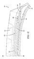
FIG. 1 is a cross-sectional view of a first embodiment of a tire of the present invention; -
FIG. 2 is a close-up view of the belt package of the tire ofFIG. 1 ; and -
FIG. 3 is a plot of strain energy density vs. a tire revolution. -
Figure 1 illustrates a first embodiment of a pneumatic tire, suitable for use as a truck tire. Thetire 10 has atread 12 with a non-skid depth D. Thetire tread 12 may comprise a plurality of circumferentially continuous ribs, which may vary, but are shown for example asribs circumferential groove - The
tire 10 further comprises acasing 14 which includes twoopposed sidewalls 16 which extend down from thetread 12 to the bead area. The casing of the tire may include aninner liner 24 which is typically formed of halobutyl rubber which forms an air impervious barrier. Thetire casing 14 further includes one or moreradial plies 18 extending from the tread, down the sidewall to thetire bead 20. Preferably theradial ply 18 is wrapped about or otherwise secured to eachannular bead 20. In the embodiment illustrated and not limited to same, there is only oneply 18 and it is wrapped around the bead in an inside out manner such that the ply ending 19 is located axially outward and radially outwards of the bead. Thebeads 20 may be any desired shape, but in this embodiment it is shown as a hexagonal configuration with steel filaments. - The tire may further optionally include an
apex 21 which may be shaped like a triangle. The ply turnup in the bead area may be optionally reinforced with achipper 23 wrapped about thebead ply 18. - The
tire 10 further includes abelt package 50 which is located between the tread and the one ormore plies 18. The belt package comprises layers of reinforcement. Theply 18 and thebelt reinforcing structure 50 are made from cord reinforced elastomeric material, wherein the cords are typically steel wire or polyamide filaments and the elastomer preferably being rubber. - The
belt reinforcing package 50 may include an optional radiallyinner transition belt 52. Thetransition belt 52 preferably is the narrowest belt of thestructure 50. Thetransition belt 52 has a belt width which preferably ranges from 0.6 to 0.9 or 0.65 to 0.85 of the tread arc width. Thetransition belt 52 preferably has an orientation that has an angle of between 45 to 70 degrees, preferably right. Thetransition belt 52 is preferably made of ultra tensile steel with a construction of 3+2x0.35. -
Belt reinforcing structure 50 includes a pair of extensible working belts, 54, 56.Belt 54 is located radially inwards ofbelt 56.Belt 54 has a width which is preferably equal or, about equal, i.e. ± 5%, to the tread arc width. Preferably, thebelt 54 has a belt width equal or substantially equal, i.e. ± 5%, to the tread arc width. The breaker angle ofbelt 54 is between 16 and 30 degrees, preferably with a right orientation, more preferably in the range of 19 to 25 degrees.Belt 54 is preferably made of high elongation wire, which is has a % elongation at 10% of breaking load of greater than 0.4%, alternatively greater than 0.6% or 0.8%, as measured from a cord taken from a cured tire. Alternatively, the cable has a % elongation at 10% of breaking load of greater than 1.7% when measurement is performed on a bare wire sample that has not been vulcanized in a tire. For example, the belt may be formed of wire having a wire construction of 3x7x, 3x4x, 4x4x. Preferably the wire has a construction of 3x7x0.22 HE (HE = high elongation steel wire). The EPI may range from 8 to 14. The wire may be a hybrid cord or a steel wire. -
Belt 56 is the second member of the working belt pair.Belt 56 has a width less than the width of belt 54 (the other working belt), and is preferably radially outward ofbelt 54. Preferably, thebelt 56 has a width less than the width ofbelt 54 by a step off, which may range from 10 to 20 mm.Belt 56 has a breaker angle between 16 and 30 degrees, preferably with a left orientation, more preferably in the range of 19 to 25 degrees.Belt 56 is preferably made of high elongation wire. Preferably, the high elongation wire is the same as the wire of thebelt 54. More preferably, the wire has the same construction with the same but opposite angular orientation as the wire ofbelt 54. - The
belt structure 50 further comprises afourth belt 58 which is preferably located between the working pair belts, 54, 56. Thefourth belt 58 is located betweenbelts fourth belt 58 has reinforcements that are oriented circumferentially at 5 degrees or less, preferably 2 degrees or less, more preferably 0 degrees. The belt is preferably formed from spirally winding a rubberized strip of one or more cords. Preferably, the strip has 3, 4 or 5 steel cords. Thebelt 58 has a width sized to avoid compression in the shoulder area. The belt width offourth belt 58 is preferably in the range of 70% to 80% of the tread arc width, and even more preferably in the range of 73-77%. Thefourth belt 58 is preferably wide enough to decrease the strain cycles in the breaker wedge, and is just stopped before the shoulder area to avoid 0 degree wire compression and a too round footprint. The belt structure offourth belt 58 may be steel formed of 4+ 3x0.35 construction, and formed of high tensile steel, which means having a % elongation at 10% of breaking load of 0.18 or more, for measurements taken from a cured tire. For measurements taken from bare cords, the % elongation at 10% of breaking load is 0.2 or more. Alternatively, the fourth belt may be formed of non-metal reinforcements such as aramid, carbon fiber, or polyketone or POK. - The belt structure may further include an
optional overlay belt 62. Theoverlay belt 62 preferably is the narrowest belt and is located radially outward of theother belts belt 62 should have the same angle and orientation as theadjacent belt 56. -
Figure 3 illustrates a finite element analysis of a belt package of the present invention.Curve 80 represents the strain energy density of a control tire versus circumferential location in the tire. The control tire had the belt construction of 55R-16R-16L-16L with high tensile steel belts. FEA analysis indicated the control tire had a life of 1.18.Curve 75 represents the strain energy density of a tire of a first example having a belt package with a zero degree belt and the working belts made of inextensible reinforcements. The belt package of the first example is 55R-21 R-0-21 L-21 L, wherein the belts were made of high tensile steel. The predicted life of the tire was 3.91.Curve 70 represents the strain energy density of a tire of a second example having a belt package with a zero degree belt and working belts the same ascurve 75, but all of the belts were made of high elongation cable. The tire of this example had the longest life of 5.11, showing a noticeable benefit of using high elongation cable. - The aspect ratio of the tire described above may vary. The aspect ratio is preferably in the range of from 0.4 to 0.6. The tire may have a net to gross ratio in the range of 70 to 90, more preferably in the range of 74 to 86, more preferably a 78 to 84.
Claims (10)
- A pneumatic tire for use on trucks, the tire comprising a tread (12) and a belt structure (50) located radially inward of the tread (12), the belt structure (50) including a pair of working belts (52, 54), wherein the working belts (52, 54) are reinforced plies each comprising parallel reinforcement elements, wherein the angle of the reinforcement elements in the respective working belt (52, 54) ranges from 16 degrees to 30 degrees from the circumferential direction, wherein the reinforcement elements are extensible having an elongation at 10% of the breaking load greater than 0.2% when measured at the reinforcement elements extracted from a cured tire, and wherein the extensible reinforcement elements are wires comprising steel or hybrid cords, characterized in that the belt structure (50) comprises a belt (58) positioned between the working belts (54, 56) comprising parallel reinforcement elements angled at less than 5 degrees from the circumferential direction.
- The tire of at least one of the previous claims wherein the extensible reinforcement elements have an elongation at 10% of breaking load greater than 0.4 %, when taken from a cured tire.
- The tire of claim 2 wherein the extensible reinforcement elements have an elongation at 10% of breaking load greater than 0.8 % or greater than 1.5 %, when taken from a cured tire.
- The tire of at least one of the previous claims wherein the radially inner working belt (54) has a width equal or about equal to the tread arc width.
- The tire of at least one of the previous claims wherein the radially outer working belt (56) has a width less than the radially inner working belt (54) and/or wherein the radially inner working belt (54) is the widest belt of the belt structure (50).
- The tire of at least one of the previous claims wherein the belt (58) comprising the parallel reinforcement elements angled at less than 5 degrees from the circumferential direction has a width in the range of from 70 to 80 percent of the tread arc width.
- The tire of at least one of the previous claims further including a transition belt (52) located radially inwards of the working belts (54, 56).
- The tire of claim 7 wherein the transition belt (52) comprises parallel reinforcement elements having an angle which ranges from 45 to 70 degrees from the circumferential direction, preferably an angle which ranges from 45 to 70 degrees right.
- The tire of claim 7 or 8 wherein the transition belt (52) has a width of 60 to 80 percent of the tread arc width.
- The tire of at least one of the previous claims wherein the aspect ratio of the tire is less than or equal to 0.6.
Applications Claiming Priority (1)
| Application Number | Priority Date | Filing Date | Title |
|---|---|---|---|
| US12/339,567 US9168789B2 (en) | 2008-12-19 | 2008-12-19 | Truck tire |
Publications (3)
| Publication Number | Publication Date |
|---|---|
| EP2199104A2 EP2199104A2 (en) | 2010-06-23 |
| EP2199104A3 EP2199104A3 (en) | 2012-02-29 |
| EP2199104B1 true EP2199104B1 (en) | 2013-05-29 |
Family
ID=41600778
Family Applications (1)
| Application Number | Title | Priority Date | Filing Date |
|---|---|---|---|
| EP09178458.7A Active EP2199104B1 (en) | 2008-12-19 | 2009-12-09 | Truck tire |
Country Status (2)
| Country | Link |
|---|---|
| US (1) | US9168789B2 (en) |
| EP (1) | EP2199104B1 (en) |
Cited By (2)
| Publication number | Priority date | Publication date | Assignee | Title |
|---|---|---|---|---|
| CN105829132A (en) * | 2013-12-18 | 2016-08-03 | 大陆轮胎德国有限公司 | Pneumatic vehicle tire |
| EP2683559B1 (en) | 2011-03-11 | 2016-11-02 | Continental Reifen Deutschland GmbH | Vehicle pneumatic tires |
Families Citing this family (10)
| Publication number | Priority date | Publication date | Assignee | Title |
|---|---|---|---|---|
| DE102010016569A1 (en) | 2010-04-21 | 2011-10-27 | Continental Reifen Deutschland Gmbh | Vehicle tires |
| JP5628946B2 (en) * | 2013-02-12 | 2014-11-19 | 株式会社ブリヂストン | Heavy duty tire |
| US20210178820A1 (en) * | 2019-12-17 | 2021-06-17 | The Goodyear Tire & Rubber Company | Pneumatic tire |
| US20210178822A1 (en) * | 2019-12-17 | 2021-06-17 | The Goodyear Tire & Rubber Company | Truck tire |
| US20210178817A1 (en) * | 2019-12-17 | 2021-06-17 | The Goodyear Tire & Rubber Company | Pneumatic tire |
| US20220063336A1 (en) * | 2020-08-31 | 2022-03-03 | The Goodyear Tire & Rubber Company | Truck tire |
| US20220063352A1 (en) * | 2020-08-31 | 2022-03-03 | The Goodyear Tire & Rubber Company | Truck tire |
| US20220185018A1 (en) * | 2020-12-14 | 2022-06-16 | The Goodyear Tire & Rubber Company | Truck tire |
| US20220185020A1 (en) * | 2020-12-14 | 2022-06-16 | The Goodyear Tire & Rubber Company | Truck tire |
| FR3117410B1 (en) * | 2020-12-15 | 2022-12-02 | Michelin & Cie | Optimized architecture of an Earthmover type tire |
Family Cites Families (44)
| Publication number | Priority date | Publication date | Assignee | Title |
|---|---|---|---|---|
| BR6792110D0 (en) * | 1966-10-25 | 1973-06-12 | Pirelli | TROLLEY RING FOR PNEUMATICS WITH SEPARATE TIRES |
| NL169158C (en) * | 1969-07-29 | 1982-06-16 | Pirelli | TREADMILL FOR AN AIRBAND WITH A REMOVABLE TREAD, AND AN AIRBAND WITH SUCH A TREADMILL. |
| CH518192A (en) * | 1970-03-12 | 1972-01-31 | Pirelli | Tread ring for tread tire separated from the carcass |
| IT1054931B (en) | 1976-01-05 | 1981-11-30 | Pirelli | IMPROVEMENT WITH RADIAL CARCASS TIRES |
| DE2602424A1 (en) | 1976-01-23 | 1977-07-28 | Phoenix Gummiwerke Ag | Crossply tyre - with high resistance at its shoulder produced by circumferential steel and crossed fabric core plies |
| US4688615A (en) * | 1985-05-28 | 1987-08-25 | The Goodyear Tire & Rubber Company | Reinforcing structure for a rubber article |
| US4838966A (en) | 1986-11-12 | 1989-06-13 | The Armstrong Rubber Co. | Woven endless tire reinforcing belt and method for producing same |
| GB2201925B (en) | 1987-03-12 | 1991-02-27 | Dunlop Ltd | Radial ply tyre |
| ES2068901T3 (en) | 1988-10-14 | 1995-05-01 | Bridgestone Corp | RADIAL TIRE FOR PLANE. |
| US5225013A (en) | 1989-03-14 | 1993-07-06 | Bridgestone Corporation | Pneumatic radial tire including wavy or zigzag belt cords |
| JP2702835B2 (en) * | 1990-10-29 | 1998-01-26 | 住友ゴム工業株式会社 | Radial tires for motorcycles |
| JPH04173404A (en) | 1990-11-06 | 1992-06-22 | Sumitomo Rubber Ind Ltd | Pneumatic tire |
| JP3126516B2 (en) | 1991-10-29 | 2001-01-22 | 株式会社ブリヂストン | Aircraft radial tires |
| JP2628939B2 (en) | 1991-02-28 | 1997-07-09 | 住友ゴム工業株式会社 | Pneumatic tire |
| US5465773A (en) | 1993-04-30 | 1995-11-14 | Bridgestone Corporation | Pneumatic radial tires with zigzag belt and rubberized cord ply belt reinforcing layer |
| JPH07186615A (en) | 1993-12-28 | 1995-07-25 | Sumitomo Rubber Ind Ltd | Pneumatic radial tire for passenger car |
| FR2719257B1 (en) * | 1994-04-28 | 1996-07-19 | Dunlop Sa | Reinforced radial tire for trucks. |
| JP3532981B2 (en) | 1994-12-13 | 2004-05-31 | 株式会社ブリヂストン | Pneumatic radial tire |
| FR2728510A1 (en) * | 1994-12-23 | 1996-06-28 | Michelin & Cie | T / H SHAPE TIRE LESS THAN OR EQUAL TO 0.6 |
| US6065518A (en) * | 1995-08-01 | 2000-05-23 | Sumitomo Rubber Industries, Ltd. | Heavy duty pneumatic tire with high elongation steel belt cord |
| US5843583A (en) * | 1996-02-15 | 1998-12-01 | N.V. Bekaert S.A. | Cord with high non-structural elongation |
| EP0875402A4 (en) | 1996-07-25 | 2001-03-14 | Yokohama Rubber Co Ltd | Pneumatic radial tire |
| FR2757799B1 (en) | 1996-12-27 | 1999-02-05 | Michelin & Cie | SUMMIT FRAME FOR AIRCRAFT TIRES |
| FR2759945B1 (en) * | 1997-02-24 | 1999-04-02 | Michelin & Cie | T / H SHAPE TIRE LESS THAN OR EQUAL TO 0.6 |
| JP3198077B2 (en) | 1997-06-27 | 2001-08-13 | 住友ゴム工業株式会社 | Pneumatic tire |
| US6352093B1 (en) | 1999-12-28 | 2002-03-05 | The Goodyear Tire & Rubber Company | Continuous folded belt and splice therefor |
| US6658836B2 (en) | 2001-03-14 | 2003-12-09 | The Goodyear Tire & Rubber Company | Hybrid cord |
| US7104299B2 (en) * | 2001-04-23 | 2006-09-12 | The Goodyear Tire & Rubber Company | Two piece tire with improved tire tread belt |
| EP1477333B1 (en) | 2002-01-24 | 2018-06-20 | Bridgestone Corporation | Pneumatic radial tire |
| US7404425B2 (en) | 2002-04-24 | 2008-07-29 | The Goodyear Tire & Rubber Company | Belt package for super single truck tires |
| FR2857620B1 (en) * | 2003-07-18 | 2005-08-19 | Michelin Soc Tech | PNEUMATIC FOR HEAVY VEHICLES |
| US7360571B2 (en) | 2003-09-16 | 2008-04-22 | The Goodyear Tire & Rubber Company | Pneumatic tire with composite belt structure |
| US7216684B2 (en) | 2003-12-29 | 2007-05-15 | The Goodyear Tire & Rubber Company | Pneumatic aviation tire |
| FR2870163B1 (en) | 2004-05-13 | 2007-09-14 | Michelin Soc Tech | PNEUMATIC FOR HEAVY VEHICLES |
| JP4041479B2 (en) * | 2004-08-06 | 2008-01-30 | 住友ゴム工業株式会社 | Heavy duty tire |
| US7503363B2 (en) | 2005-03-30 | 2009-03-17 | The Goodyear Tire & Rubber Company | Belt package for super single truck tires |
| JP4938327B2 (en) | 2005-04-21 | 2012-05-23 | 株式会社ブリヂストン | Radial tire for aircraft and method for manufacturing radial tire for aircraft |
| JP4747773B2 (en) * | 2005-10-11 | 2011-08-17 | 横浜ゴム株式会社 | Pneumatic tire |
| US7458200B2 (en) * | 2005-12-08 | 2008-12-02 | The Goodyear Tire & Rubber Co. | High elongation cable |
| JP4907976B2 (en) | 2005-12-21 | 2012-04-04 | 株式会社ブリヂストン | Pneumatic radial tire for aircraft |
| JP4953632B2 (en) | 2006-01-04 | 2012-06-13 | 株式会社ブリヂストン | Aircraft radial tire |
| JP4953633B2 (en) | 2006-01-04 | 2012-06-13 | 株式会社ブリヂストン | Aircraft radial tire |
| US20100154974A1 (en) | 2008-12-19 | 2010-06-24 | Francois Pierre Charles Gerard Georges | Method of making a pneumatic tire |
| DE102010060257A1 (en) * | 2010-10-29 | 2012-05-03 | Continental Reifen Deutschland Gmbh | Vehicle tires |
-
2008
- 2008-12-19 US US12/339,567 patent/US9168789B2/en active Active
-
2009
- 2009-12-09 EP EP09178458.7A patent/EP2199104B1/en active Active
Cited By (2)
| Publication number | Priority date | Publication date | Assignee | Title |
|---|---|---|---|---|
| EP2683559B1 (en) | 2011-03-11 | 2016-11-02 | Continental Reifen Deutschland GmbH | Vehicle pneumatic tires |
| CN105829132A (en) * | 2013-12-18 | 2016-08-03 | 大陆轮胎德国有限公司 | Pneumatic vehicle tire |
Also Published As
| Publication number | Publication date |
|---|---|
| US9168789B2 (en) | 2015-10-27 |
| EP2199104A2 (en) | 2010-06-23 |
| EP2199104A3 (en) | 2012-02-29 |
| US20100154958A1 (en) | 2010-06-24 |
Similar Documents
| Publication | Publication Date | Title |
|---|---|---|
| EP2199104B1 (en) | Truck tire | |
| EP3838623B1 (en) | Truck tire | |
| CA2080852A1 (en) | Truck tire with split overlay | |
| EP3838619B1 (en) | Pneumatic tire | |
| EP2463124A2 (en) | Pneumatic tire | |
| EP0980770B1 (en) | Pneumatic radial tires | |
| EP4144539A1 (en) | Pneumatic tire for use on truck | |
| EP2199108A1 (en) | Pneumatic tire | |
| EP3838621B1 (en) | Pneumatic tire | |
| US20080163969A1 (en) | Pneumatic tire with buttressed sidewall | |
| US20230191844A1 (en) | Truck tire | |
| US20230191845A1 (en) | Truck tire | |
| US20230191842A1 (en) | Truck tire | |
| US20220185020A1 (en) | Truck tire | |
| US20220185018A1 (en) | Truck tire | |
| US20220063336A1 (en) | Truck tire | |
| US7267149B2 (en) | Pneumatic tire with improved crown durability | |
| US20220063352A1 (en) | Truck tire | |
| US20220185035A1 (en) | Tire with improved bead structure | |
| EP4015243B1 (en) | Tire with protective belt structure | |
| US20210178817A1 (en) | Pneumatic tire |
Legal Events
| Date | Code | Title | Description |
|---|---|---|---|
| PUAI | Public reference made under article 153(3) epc to a published international application that has entered the european phase |
Free format text: ORIGINAL CODE: 0009012 |
|
| AK | Designated contracting states |
Kind code of ref document: A2 Designated state(s): AT BE BG CH CY CZ DE DK EE ES FI FR GB GR HR HU IE IS IT LI LT LU LV MC MK MT NL NO PL PT RO SE SI SK SM TR |
|
| AX | Request for extension of the european patent |
Extension state: AL BA RS |
|
| PUAL | Search report despatched |
Free format text: ORIGINAL CODE: 0009013 |
|
| AK | Designated contracting states |
Kind code of ref document: A3 Designated state(s): AT BE BG CH CY CZ DE DK EE ES FI FR GB GR HR HU IE IS IT LI LT LU LV MC MK MT NL NO PL PT RO SE SI SK SM TR |
|
| AX | Request for extension of the european patent |
Extension state: AL BA RS |
|
| RIC1 | Information provided on ipc code assigned before grant |
Ipc: B60C 9/20 20060101AFI20120126BHEP |
|
| 17P | Request for examination filed |
Effective date: 20120829 |
|
| GRAP | Despatch of communication of intention to grant a patent |
Free format text: ORIGINAL CODE: EPIDOSNIGR1 |
|
| GRAS | Grant fee paid |
Free format text: ORIGINAL CODE: EPIDOSNIGR3 |
|
| GRAA | (expected) grant |
Free format text: ORIGINAL CODE: 0009210 |
|
| AK | Designated contracting states |
Kind code of ref document: B1 Designated state(s): AT BE BG CH CY CZ DE DK EE ES FI FR GB GR HR HU IE IS IT LI LT LU LV MC MK MT NL NO PL PT RO SE SI SK SM TR |
|
| REG | Reference to a national code |
Ref country code: GB Ref legal event code: FG4D |
|
| REG | Reference to a national code |
Ref country code: CH Ref legal event code: EP |
|
| REG | Reference to a national code |
Ref country code: AT Ref legal event code: REF Ref document number: 614128 Country of ref document: AT Kind code of ref document: T Effective date: 20130615 |
|
| REG | Reference to a national code |
Ref country code: IE Ref legal event code: FG4D |
|
| REG | Reference to a national code |
Ref country code: DE Ref legal event code: R096 Ref document number: 602009015977 Country of ref document: DE Effective date: 20130725 |
|
| REG | Reference to a national code |
Ref country code: AT Ref legal event code: MK05 Ref document number: 614128 Country of ref document: AT Kind code of ref document: T Effective date: 20130529 |
|
| REG | Reference to a national code |
Ref country code: LT Ref legal event code: MG4D |
|
| PG25 | Lapsed in a contracting state [announced via postgrant information from national office to epo] |
Ref country code: SE Free format text: LAPSE BECAUSE OF FAILURE TO SUBMIT A TRANSLATION OF THE DESCRIPTION OR TO PAY THE FEE WITHIN THE PRESCRIBED TIME-LIMIT Effective date: 20130529 Ref country code: ES Free format text: LAPSE BECAUSE OF FAILURE TO SUBMIT A TRANSLATION OF THE DESCRIPTION OR TO PAY THE FEE WITHIN THE PRESCRIBED TIME-LIMIT Effective date: 20130909 Ref country code: SI Free format text: LAPSE BECAUSE OF FAILURE TO SUBMIT A TRANSLATION OF THE DESCRIPTION OR TO PAY THE FEE WITHIN THE PRESCRIBED TIME-LIMIT Effective date: 20130529 Ref country code: FI Free format text: LAPSE BECAUSE OF FAILURE TO SUBMIT A TRANSLATION OF THE DESCRIPTION OR TO PAY THE FEE WITHIN THE PRESCRIBED TIME-LIMIT Effective date: 20130529 Ref country code: GR Free format text: LAPSE BECAUSE OF FAILURE TO SUBMIT A TRANSLATION OF THE DESCRIPTION OR TO PAY THE FEE WITHIN THE PRESCRIBED TIME-LIMIT Effective date: 20130830 Ref country code: NO Free format text: LAPSE BECAUSE OF FAILURE TO SUBMIT A TRANSLATION OF THE DESCRIPTION OR TO PAY THE FEE WITHIN THE PRESCRIBED TIME-LIMIT Effective date: 20130829 Ref country code: AT Free format text: LAPSE BECAUSE OF FAILURE TO SUBMIT A TRANSLATION OF THE DESCRIPTION OR TO PAY THE FEE WITHIN THE PRESCRIBED TIME-LIMIT Effective date: 20130529 Ref country code: PT Free format text: LAPSE BECAUSE OF FAILURE TO SUBMIT A TRANSLATION OF THE DESCRIPTION OR TO PAY THE FEE WITHIN THE PRESCRIBED TIME-LIMIT Effective date: 20130930 Ref country code: IS Free format text: LAPSE BECAUSE OF FAILURE TO SUBMIT A TRANSLATION OF THE DESCRIPTION OR TO PAY THE FEE WITHIN THE PRESCRIBED TIME-LIMIT Effective date: 20130929 Ref country code: LT Free format text: LAPSE BECAUSE OF FAILURE TO SUBMIT A TRANSLATION OF THE DESCRIPTION OR TO PAY THE FEE WITHIN THE PRESCRIBED TIME-LIMIT Effective date: 20130529 |
|
| REG | Reference to a national code |
Ref country code: NL Ref legal event code: VDEP Effective date: 20130529 |
|
| PG25 | Lapsed in a contracting state [announced via postgrant information from national office to epo] |
Ref country code: BG Free format text: LAPSE BECAUSE OF FAILURE TO SUBMIT A TRANSLATION OF THE DESCRIPTION OR TO PAY THE FEE WITHIN THE PRESCRIBED TIME-LIMIT Effective date: 20130829 Ref country code: HR Free format text: LAPSE BECAUSE OF FAILURE TO SUBMIT A TRANSLATION OF THE DESCRIPTION OR TO PAY THE FEE WITHIN THE PRESCRIBED TIME-LIMIT Effective date: 20130529 Ref country code: PL Free format text: LAPSE BECAUSE OF FAILURE TO SUBMIT A TRANSLATION OF THE DESCRIPTION OR TO PAY THE FEE WITHIN THE PRESCRIBED TIME-LIMIT Effective date: 20130529 |
|
| PG25 | Lapsed in a contracting state [announced via postgrant information from national office to epo] |
Ref country code: LV Free format text: LAPSE BECAUSE OF FAILURE TO SUBMIT A TRANSLATION OF THE DESCRIPTION OR TO PAY THE FEE WITHIN THE PRESCRIBED TIME-LIMIT Effective date: 20130529 |
|
| PG25 | Lapsed in a contracting state [announced via postgrant information from national office to epo] |
Ref country code: SK Free format text: LAPSE BECAUSE OF FAILURE TO SUBMIT A TRANSLATION OF THE DESCRIPTION OR TO PAY THE FEE WITHIN THE PRESCRIBED TIME-LIMIT Effective date: 20130529 Ref country code: CZ Free format text: LAPSE BECAUSE OF FAILURE TO SUBMIT A TRANSLATION OF THE DESCRIPTION OR TO PAY THE FEE WITHIN THE PRESCRIBED TIME-LIMIT Effective date: 20130529 Ref country code: EE Free format text: LAPSE BECAUSE OF FAILURE TO SUBMIT A TRANSLATION OF THE DESCRIPTION OR TO PAY THE FEE WITHIN THE PRESCRIBED TIME-LIMIT Effective date: 20130529 Ref country code: BE Free format text: LAPSE BECAUSE OF FAILURE TO SUBMIT A TRANSLATION OF THE DESCRIPTION OR TO PAY THE FEE WITHIN THE PRESCRIBED TIME-LIMIT Effective date: 20130529 Ref country code: DK Free format text: LAPSE BECAUSE OF FAILURE TO SUBMIT A TRANSLATION OF THE DESCRIPTION OR TO PAY THE FEE WITHIN THE PRESCRIBED TIME-LIMIT Effective date: 20130529 |
|
| PG25 | Lapsed in a contracting state [announced via postgrant information from national office to epo] |
Ref country code: NL Free format text: LAPSE BECAUSE OF FAILURE TO SUBMIT A TRANSLATION OF THE DESCRIPTION OR TO PAY THE FEE WITHIN THE PRESCRIBED TIME-LIMIT Effective date: 20130529 Ref country code: RO Free format text: LAPSE BECAUSE OF FAILURE TO SUBMIT A TRANSLATION OF THE DESCRIPTION OR TO PAY THE FEE WITHIN THE PRESCRIBED TIME-LIMIT Effective date: 20130529 |
|
| PLBI | Opposition filed |
Free format text: ORIGINAL CODE: 0009260 |
|
| 26 | Opposition filed |
Opponent name: MICHELIN RECHERCHE ET TECHNIQUE S.A. Effective date: 20140224 |
|
| PLAX | Notice of opposition and request to file observation + time limit sent |
Free format text: ORIGINAL CODE: EPIDOSNOBS2 |
|
| REG | Reference to a national code |
Ref country code: DE Ref legal event code: R026 Ref document number: 602009015977 Country of ref document: DE Effective date: 20140224 |
|
| PG25 | Lapsed in a contracting state [announced via postgrant information from national office to epo] |
Ref country code: MC Free format text: LAPSE BECAUSE OF FAILURE TO SUBMIT A TRANSLATION OF THE DESCRIPTION OR TO PAY THE FEE WITHIN THE PRESCRIBED TIME-LIMIT Effective date: 20130529 |
|
| REG | Reference to a national code |
Ref country code: CH Ref legal event code: PL |
|
| PLBB | Reply of patent proprietor to notice(s) of opposition received |
Free format text: ORIGINAL CODE: EPIDOSNOBS3 |
|
| GBPC | Gb: european patent ceased through non-payment of renewal fee |
Effective date: 20131209 |
|
| PG25 | Lapsed in a contracting state [announced via postgrant information from national office to epo] |
Ref country code: LU Free format text: LAPSE BECAUSE OF FAILURE TO SUBMIT A TRANSLATION OF THE DESCRIPTION OR TO PAY THE FEE WITHIN THE PRESCRIBED TIME-LIMIT Effective date: 20131209 |
|
| REG | Reference to a national code |
Ref country code: IE Ref legal event code: MM4A |
|
| PG25 | Lapsed in a contracting state [announced via postgrant information from national office to epo] |
Ref country code: IE Free format text: LAPSE BECAUSE OF NON-PAYMENT OF DUE FEES Effective date: 20131209 Ref country code: CH Free format text: LAPSE BECAUSE OF NON-PAYMENT OF DUE FEES Effective date: 20131231 Ref country code: LI Free format text: LAPSE BECAUSE OF NON-PAYMENT OF DUE FEES Effective date: 20131231 |
|
| PG25 | Lapsed in a contracting state [announced via postgrant information from national office to epo] |
Ref country code: GB Free format text: LAPSE BECAUSE OF NON-PAYMENT OF DUE FEES Effective date: 20131209 |
|
| PG25 | Lapsed in a contracting state [announced via postgrant information from national office to epo] |
Ref country code: SM Free format text: LAPSE BECAUSE OF FAILURE TO SUBMIT A TRANSLATION OF THE DESCRIPTION OR TO PAY THE FEE WITHIN THE PRESCRIBED TIME-LIMIT Effective date: 20130529 |
|
| PG25 | Lapsed in a contracting state [announced via postgrant information from national office to epo] |
Ref country code: TR Free format text: LAPSE BECAUSE OF FAILURE TO SUBMIT A TRANSLATION OF THE DESCRIPTION OR TO PAY THE FEE WITHIN THE PRESCRIBED TIME-LIMIT Effective date: 20130529 Ref country code: CY Free format text: LAPSE BECAUSE OF FAILURE TO SUBMIT A TRANSLATION OF THE DESCRIPTION OR TO PAY THE FEE WITHIN THE PRESCRIBED TIME-LIMIT Effective date: 20130529 |
|
| PG25 | Lapsed in a contracting state [announced via postgrant information from national office to epo] |
Ref country code: MK Free format text: LAPSE BECAUSE OF FAILURE TO SUBMIT A TRANSLATION OF THE DESCRIPTION OR TO PAY THE FEE WITHIN THE PRESCRIBED TIME-LIMIT Effective date: 20130529 Ref country code: HU Free format text: LAPSE BECAUSE OF FAILURE TO SUBMIT A TRANSLATION OF THE DESCRIPTION OR TO PAY THE FEE WITHIN THE PRESCRIBED TIME-LIMIT; INVALID AB INITIO Effective date: 20091209 |
|
| PG25 | Lapsed in a contracting state [announced via postgrant information from national office to epo] |
Ref country code: MT Free format text: LAPSE BECAUSE OF FAILURE TO SUBMIT A TRANSLATION OF THE DESCRIPTION OR TO PAY THE FEE WITHIN THE PRESCRIBED TIME-LIMIT Effective date: 20130529 |
|
| REG | Reference to a national code |
Ref country code: FR Ref legal event code: PLFP Year of fee payment: 7 |
|
| PLCK | Communication despatched that opposition was rejected |
Free format text: ORIGINAL CODE: EPIDOSNREJ1 |
|
| APBM | Appeal reference recorded |
Free format text: ORIGINAL CODE: EPIDOSNREFNO |
|
| APBP | Date of receipt of notice of appeal recorded |
Free format text: ORIGINAL CODE: EPIDOSNNOA2O |
|
| APAH | Appeal reference modified |
Free format text: ORIGINAL CODE: EPIDOSCREFNO |
|
| APBQ | Date of receipt of statement of grounds of appeal recorded |
Free format text: ORIGINAL CODE: EPIDOSNNOA3O |
|
| APAH | Appeal reference modified |
Free format text: ORIGINAL CODE: EPIDOSCREFNO |
|
| REG | Reference to a national code |
Ref country code: FR Ref legal event code: PLFP Year of fee payment: 8 |
|
| REG | Reference to a national code |
Ref country code: FR Ref legal event code: PLFP Year of fee payment: 9 |
|
| APBU | Appeal procedure closed |
Free format text: ORIGINAL CODE: EPIDOSNNOA9O |
|
| REG | Reference to a national code |
Ref country code: DE Ref legal event code: R100 Ref document number: 602009015977 Country of ref document: DE |
|
| PLBN | Opposition rejected |
Free format text: ORIGINAL CODE: 0009273 |
|
| STAA | Information on the status of an ep patent application or granted ep patent |
Free format text: STATUS: OPPOSITION REJECTED |
|
| 27O | Opposition rejected |
Effective date: 20181218 |
|
| PGFP | Annual fee paid to national office [announced via postgrant information from national office to epo] |
Ref country code: FR Payment date: 20230929 Year of fee payment: 15 |
|
| PGFP | Annual fee paid to national office [announced via postgrant information from national office to epo] |
Ref country code: IT Payment date: 20231110 Year of fee payment: 15 Ref country code: DE Payment date: 20231017 Year of fee payment: 15 |