EP3960333A1 - Processing machine - Google Patents
Processing machine Download PDFInfo
- Publication number
- EP3960333A1 EP3960333A1 EP20806272.9A EP20806272A EP3960333A1 EP 3960333 A1 EP3960333 A1 EP 3960333A1 EP 20806272 A EP20806272 A EP 20806272A EP 3960333 A1 EP3960333 A1 EP 3960333A1
- Authority
- EP
- European Patent Office
- Prior art keywords
- processing
- opening
- wall
- blower
- processing area
- Prior art date
- Legal status (The legal status is an assumption and is not a legal conclusion. Google has not performed a legal analysis and makes no representation as to the accuracy of the status listed.)
- Granted
Links
Images


Classifications
-
- B—PERFORMING OPERATIONS; TRANSPORTING
- B29—WORKING OF PLASTICS; WORKING OF SUBSTANCES IN A PLASTIC STATE IN GENERAL
- B29C—SHAPING OR JOINING OF PLASTICS; SHAPING OF MATERIAL IN A PLASTIC STATE, NOT OTHERWISE PROVIDED FOR; AFTER-TREATMENT OF THE SHAPED PRODUCTS, e.g. REPAIRING
- B29C64/00—Additive manufacturing, i.e. manufacturing of three-dimensional [3D] objects by additive deposition, additive agglomeration or additive layering, e.g. by 3D printing, stereolithography or selective laser sintering
- B29C64/30—Auxiliary operations or equipment
- B29C64/364—Conditioning of environment
-
- B—PERFORMING OPERATIONS; TRANSPORTING
- B22—CASTING; POWDER METALLURGY
- B22F—WORKING METALLIC POWDER; MANUFACTURE OF ARTICLES FROM METALLIC POWDER; MAKING METALLIC POWDER; APPARATUS OR DEVICES SPECIALLY ADAPTED FOR METALLIC POWDER
- B22F10/00—Additive manufacturing of workpieces or articles from metallic powder
- B22F10/20—Direct sintering or melting
- B22F10/25—Direct deposition of metal particles, e.g. direct metal deposition [DMD] or laser engineered net shaping [LENS]
-
- B—PERFORMING OPERATIONS; TRANSPORTING
- B22—CASTING; POWDER METALLURGY
- B22F—WORKING METALLIC POWDER; MANUFACTURE OF ARTICLES FROM METALLIC POWDER; MAKING METALLIC POWDER; APPARATUS OR DEVICES SPECIALLY ADAPTED FOR METALLIC POWDER
- B22F10/00—Additive manufacturing of workpieces or articles from metallic powder
- B22F10/20—Direct sintering or melting
- B22F10/28—Powder bed fusion, e.g. selective laser melting [SLM] or electron beam melting [EBM]
-
- B—PERFORMING OPERATIONS; TRANSPORTING
- B22—CASTING; POWDER METALLURGY
- B22F—WORKING METALLIC POWDER; MANUFACTURE OF ARTICLES FROM METALLIC POWDER; MAKING METALLIC POWDER; APPARATUS OR DEVICES SPECIALLY ADAPTED FOR METALLIC POWDER
- B22F10/00—Additive manufacturing of workpieces or articles from metallic powder
- B22F10/30—Process control
- B22F10/32—Process control of the atmosphere, e.g. composition or pressure in a building chamber
- B22F10/322—Process control of the atmosphere, e.g. composition or pressure in a building chamber of the gas flow, e.g. rate or direction
-
- B—PERFORMING OPERATIONS; TRANSPORTING
- B22—CASTING; POWDER METALLURGY
- B22F—WORKING METALLIC POWDER; MANUFACTURE OF ARTICLES FROM METALLIC POWDER; MAKING METALLIC POWDER; APPARATUS OR DEVICES SPECIALLY ADAPTED FOR METALLIC POWDER
- B22F12/00—Apparatus or devices specially adapted for additive manufacturing; Auxiliary means for additive manufacturing; Combinations of additive manufacturing apparatus or devices with other processing apparatus or devices
- B22F12/38—Housings, e.g. machine housings
-
- B—PERFORMING OPERATIONS; TRANSPORTING
- B22—CASTING; POWDER METALLURGY
- B22F—WORKING METALLIC POWDER; MANUFACTURE OF ARTICLES FROM METALLIC POWDER; MAKING METALLIC POWDER; APPARATUS OR DEVICES SPECIALLY ADAPTED FOR METALLIC POWDER
- B22F12/00—Apparatus or devices specially adapted for additive manufacturing; Auxiliary means for additive manufacturing; Combinations of additive manufacturing apparatus or devices with other processing apparatus or devices
- B22F12/70—Gas flow means
-
- B—PERFORMING OPERATIONS; TRANSPORTING
- B22—CASTING; POWDER METALLURGY
- B22F—WORKING METALLIC POWDER; MANUFACTURE OF ARTICLES FROM METALLIC POWDER; MAKING METALLIC POWDER; APPARATUS OR DEVICES SPECIALLY ADAPTED FOR METALLIC POWDER
- B22F12/00—Apparatus or devices specially adapted for additive manufacturing; Auxiliary means for additive manufacturing; Combinations of additive manufacturing apparatus or devices with other processing apparatus or devices
- B22F12/80—Plants, production lines or modules
- B22F12/82—Combination of additive manufacturing apparatus or devices with other processing apparatus or devices
-
- B—PERFORMING OPERATIONS; TRANSPORTING
- B23—MACHINE TOOLS; METAL-WORKING NOT OTHERWISE PROVIDED FOR
- B23K—SOLDERING OR UNSOLDERING; WELDING; CLADDING OR PLATING BY SOLDERING OR WELDING; CUTTING BY APPLYING HEAT LOCALLY, e.g. FLAME CUTTING; WORKING BY LASER BEAM
- B23K26/00—Working by laser beam, e.g. welding, cutting or boring
- B23K26/16—Removal of by-products, e.g. particles or vapours produced during treatment of a workpiece
-
- B—PERFORMING OPERATIONS; TRANSPORTING
- B23—MACHINE TOOLS; METAL-WORKING NOT OTHERWISE PROVIDED FOR
- B23K—SOLDERING OR UNSOLDERING; WELDING; CLADDING OR PLATING BY SOLDERING OR WELDING; CUTTING BY APPLYING HEAT LOCALLY, e.g. FLAME CUTTING; WORKING BY LASER BEAM
- B23K26/00—Working by laser beam, e.g. welding, cutting or boring
- B23K26/34—Laser welding for purposes other than joining
- B23K26/342—Build-up welding
-
- B—PERFORMING OPERATIONS; TRANSPORTING
- B29—WORKING OF PLASTICS; WORKING OF SUBSTANCES IN A PLASTIC STATE IN GENERAL
- B29C—SHAPING OR JOINING OF PLASTICS; SHAPING OF MATERIAL IN A PLASTIC STATE, NOT OTHERWISE PROVIDED FOR; AFTER-TREATMENT OF THE SHAPED PRODUCTS, e.g. REPAIRING
- B29C64/00—Additive manufacturing, i.e. manufacturing of three-dimensional [3D] objects by additive deposition, additive agglomeration or additive layering, e.g. by 3D printing, stereolithography or selective laser sintering
- B29C64/10—Processes of additive manufacturing
- B29C64/106—Processes of additive manufacturing using only liquids or viscous materials, e.g. depositing a continuous bead of viscous material
-
- B—PERFORMING OPERATIONS; TRANSPORTING
- B29—WORKING OF PLASTICS; WORKING OF SUBSTANCES IN A PLASTIC STATE IN GENERAL
- B29C—SHAPING OR JOINING OF PLASTICS; SHAPING OF MATERIAL IN A PLASTIC STATE, NOT OTHERWISE PROVIDED FOR; AFTER-TREATMENT OF THE SHAPED PRODUCTS, e.g. REPAIRING
- B29C64/00—Additive manufacturing, i.e. manufacturing of three-dimensional [3D] objects by additive deposition, additive agglomeration or additive layering, e.g. by 3D printing, stereolithography or selective laser sintering
- B29C64/10—Processes of additive manufacturing
- B29C64/141—Processes of additive manufacturing using only solid materials
- B29C64/153—Processes of additive manufacturing using only solid materials using layers of powder being selectively joined, e.g. by selective laser sintering or melting
-
- B—PERFORMING OPERATIONS; TRANSPORTING
- B29—WORKING OF PLASTICS; WORKING OF SUBSTANCES IN A PLASTIC STATE IN GENERAL
- B29C—SHAPING OR JOINING OF PLASTICS; SHAPING OF MATERIAL IN A PLASTIC STATE, NOT OTHERWISE PROVIDED FOR; AFTER-TREATMENT OF THE SHAPED PRODUCTS, e.g. REPAIRING
- B29C64/00—Additive manufacturing, i.e. manufacturing of three-dimensional [3D] objects by additive deposition, additive agglomeration or additive layering, e.g. by 3D printing, stereolithography or selective laser sintering
- B29C64/20—Apparatus for additive manufacturing; Details thereof or accessories therefor
- B29C64/25—Housings, e.g. machine housings
-
- B—PERFORMING OPERATIONS; TRANSPORTING
- B29—WORKING OF PLASTICS; WORKING OF SUBSTANCES IN A PLASTIC STATE IN GENERAL
- B29C—SHAPING OR JOINING OF PLASTICS; SHAPING OF MATERIAL IN A PLASTIC STATE, NOT OTHERWISE PROVIDED FOR; AFTER-TREATMENT OF THE SHAPED PRODUCTS, e.g. REPAIRING
- B29C64/00—Additive manufacturing, i.e. manufacturing of three-dimensional [3D] objects by additive deposition, additive agglomeration or additive layering, e.g. by 3D printing, stereolithography or selective laser sintering
- B29C64/20—Apparatus for additive manufacturing; Details thereof or accessories therefor
- B29C64/255—Enclosures for the building material, e.g. powder containers
-
- B—PERFORMING OPERATIONS; TRANSPORTING
- B29—WORKING OF PLASTICS; WORKING OF SUBSTANCES IN A PLASTIC STATE IN GENERAL
- B29C—SHAPING OR JOINING OF PLASTICS; SHAPING OF MATERIAL IN A PLASTIC STATE, NOT OTHERWISE PROVIDED FOR; AFTER-TREATMENT OF THE SHAPED PRODUCTS, e.g. REPAIRING
- B29C64/00—Additive manufacturing, i.e. manufacturing of three-dimensional [3D] objects by additive deposition, additive agglomeration or additive layering, e.g. by 3D printing, stereolithography or selective laser sintering
- B29C64/30—Auxiliary operations or equipment
- B29C64/307—Handling of material to be used in additive manufacturing
- B29C64/321—Feeding
-
- B—PERFORMING OPERATIONS; TRANSPORTING
- B29—WORKING OF PLASTICS; WORKING OF SUBSTANCES IN A PLASTIC STATE IN GENERAL
- B29C—SHAPING OR JOINING OF PLASTICS; SHAPING OF MATERIAL IN A PLASTIC STATE, NOT OTHERWISE PROVIDED FOR; AFTER-TREATMENT OF THE SHAPED PRODUCTS, e.g. REPAIRING
- B29C64/00—Additive manufacturing, i.e. manufacturing of three-dimensional [3D] objects by additive deposition, additive agglomeration or additive layering, e.g. by 3D printing, stereolithography or selective laser sintering
- B29C64/30—Auxiliary operations or equipment
- B29C64/35—Cleaning
-
- B—PERFORMING OPERATIONS; TRANSPORTING
- B29—WORKING OF PLASTICS; WORKING OF SUBSTANCES IN A PLASTIC STATE IN GENERAL
- B29C—SHAPING OR JOINING OF PLASTICS; SHAPING OF MATERIAL IN A PLASTIC STATE, NOT OTHERWISE PROVIDED FOR; AFTER-TREATMENT OF THE SHAPED PRODUCTS, e.g. REPAIRING
- B29C64/00—Additive manufacturing, i.e. manufacturing of three-dimensional [3D] objects by additive deposition, additive agglomeration or additive layering, e.g. by 3D printing, stereolithography or selective laser sintering
- B29C64/30—Auxiliary operations or equipment
- B29C64/357—Recycling
-
- B—PERFORMING OPERATIONS; TRANSPORTING
- B33—ADDITIVE MANUFACTURING TECHNOLOGY
- B33Y—ADDITIVE MANUFACTURING, i.e. MANUFACTURING OF THREE-DIMENSIONAL [3D] OBJECTS BY ADDITIVE DEPOSITION, ADDITIVE AGGLOMERATION OR ADDITIVE LAYERING, e.g. BY 3D PRINTING, STEREOLITHOGRAPHY OR SELECTIVE LASER SINTERING
- B33Y30/00—Apparatus for additive manufacturing; Details thereof or accessories therefor
-
- B—PERFORMING OPERATIONS; TRANSPORTING
- B33—ADDITIVE MANUFACTURING TECHNOLOGY
- B33Y—ADDITIVE MANUFACTURING, i.e. MANUFACTURING OF THREE-DIMENSIONAL [3D] OBJECTS BY ADDITIVE DEPOSITION, ADDITIVE AGGLOMERATION OR ADDITIVE LAYERING, e.g. BY 3D PRINTING, STEREOLITHOGRAPHY OR SELECTIVE LASER SINTERING
- B33Y40/00—Auxiliary operations or equipment, e.g. for material handling
-
- B—PERFORMING OPERATIONS; TRANSPORTING
- B22—CASTING; POWDER METALLURGY
- B22F—WORKING METALLIC POWDER; MANUFACTURE OF ARTICLES FROM METALLIC POWDER; MAKING METALLIC POWDER; APPARATUS OR DEVICES SPECIALLY ADAPTED FOR METALLIC POWDER
- B22F10/00—Additive manufacturing of workpieces or articles from metallic powder
- B22F10/70—Recycling
- B22F10/77—Recycling of gas
-
- B—PERFORMING OPERATIONS; TRANSPORTING
- B33—ADDITIVE MANUFACTURING TECHNOLOGY
- B33Y—ADDITIVE MANUFACTURING, i.e. MANUFACTURING OF THREE-DIMENSIONAL [3D] OBJECTS BY ADDITIVE DEPOSITION, ADDITIVE AGGLOMERATION OR ADDITIVE LAYERING, e.g. BY 3D PRINTING, STEREOLITHOGRAPHY OR SELECTIVE LASER SINTERING
- B33Y50/00—Data acquisition or data processing for additive manufacturing
- B33Y50/02—Data acquisition or data processing for additive manufacturing for controlling or regulating additive manufacturing processes
-
- Y—GENERAL TAGGING OF NEW TECHNOLOGICAL DEVELOPMENTS; GENERAL TAGGING OF CROSS-SECTIONAL TECHNOLOGIES SPANNING OVER SEVERAL SECTIONS OF THE IPC; TECHNICAL SUBJECTS COVERED BY FORMER USPC CROSS-REFERENCE ART COLLECTIONS [XRACs] AND DIGESTS
- Y02—TECHNOLOGIES OR APPLICATIONS FOR MITIGATION OR ADAPTATION AGAINST CLIMATE CHANGE
- Y02P—CLIMATE CHANGE MITIGATION TECHNOLOGIES IN THE PRODUCTION OR PROCESSING OF GOODS
- Y02P10/00—Technologies related to metal processing
- Y02P10/25—Process efficiency
Definitions
- the present invention relates to a processing machine.
- WO 2011/49143 discloses an apparatus manufacturing a three-dimensional shaped object by using a powder sintering lamination method.
- a supply nozzle is provided on a wall surface of a chamber.
- a local gas flow is formed in the chamber by supplying a gas from the supply nozzle.
- at least a part of fume generated by powder sintering lamination is discharged to outside of the chamber accompanying the local gas flow.
- Japanese Patent Laying-Open No. 2012-224919 (PTL 2), Japanese Patent Laying-Open No. 2018-127710 (PTL 3), Japanese Patent Laying-Open No. 2016-107454 (PTL 4), and Japanese Patent Laying-Open No. 2016-153529 (PTL 5) are documents disclosing conventional processing machines.
- Examples of a method of performing additive manufacturing (AM) processing for a workpiece by a molten material include directed energy deposition (DED), selective laser melting (SLM), thermal spraying, and the like. Use of such methods generates particulates (fume) by the AM processing for the workpiece, and thus the particulates are required to be discharged from the processing area efficiently.
- DED directed energy deposition
- SLM selective laser melting
- thermal spraying and the like.
- an object of the present invention is to solve the above problem, and to provide a processing machine capable of efficiently discharging particulates generated by additive manufacturing processing for a workpiece from a processing area.
- a processing machine is a processing machine that performs additive manufacturing processing for a workpiece with a molten material.
- the processing machine includes a first cover having a first wall and a second wall that face each other in a horizontal direction and forming a processing area between the first wall and the second wall.
- the first wall is provided with a first opening allowing a gas to flow into the processing area.
- the processing machine further includes an induction flow generator that generates a gas flow flowing from below to upward along the second wall.
- the first cover is provided with a second opening allowing the gas to flow out from the processing area.
- the processing machine configured as described above can generate a gas flow flowing from below to upward along the second wall (hereinafter, referred to as "induction flow") by the induction flow generator.
- induction flow a gas flow along the horizontal direction that the gas flowing into the processing area through the first opening flows from the first wall provided with the first opening toward the second wall through which the induction flow flows, and an upward gas flow that the gas flowing from the first wall toward the second wall flows from below to upward by being guided by the induction flow can be generated in the processing area.
- the particulates generated in the processing area due to the AM processing are carried by this gas flow and is discharged to outside through the second opening, and thus the particulates can be efficiently discharged.
- the processing machine preferably further includes a second cover that forms an accommodation space and accommodates, in the accommodation space, a material powder supply device that supplies the material powder toward the processing area.
- the induction flow generator includes a first blower that supplies a gas from the accommodation space into the processing area, and a duct that feeds the gas supplied from the accommodation space into the processing area as a gas flow flowing from below to upward.
- the particulates generated in the accommodation space can also be carried by the induction flow and discharged to outside. Therefore, the particulates can be discharged from both the processing area and the accommodation space with a simple configuration.
- the processing machine preferably further includes a dust collector, a second blower that supplies a gas from the processing area to the dust collector through the second opening, and a control unit that controls the first blower and the second blower.
- the control unit operates the first blower and the second blower while the AM processing for the workpiece is performed, and operates the first blower and stops the second blower while the additional manufacturing processing for the workpiece is not performed and the material powder is refilled to the material powder supply device.
- the first blower and the second blower are selectively operated in accordance with timing at which particulates are generated in each of the processing area and the accommodation space. This makes it possible to discharge the particulates from the processing area and the accommodation space while suppressing energy consumption in the blower.
- the first cover preferably further includes a ceiling.
- the second opening is provided in the ceiling.
- the particulates can be more efficiently discharged to outside through the second opening.
- the induction flow generator preferably includes a duct having an outlet and feeding a gas into the processing area through the outlet.
- the outlet is provided at a position as high as the first opening or at a position lower than the first opening.
- the processing machine configured as described above can allow the gas flowing from the first wall toward the second wall to collide with the induction flow more reliably. This facilitates generation of an upward gas flow flowing from below to upward, and thus the particulates can be more efficiently discharged to outside.
- the processing machine preferably further includes a rectifying mechanism that is provided with the first opening and changes a gas flowing into the processing area into a gas flow along the horizontal direction.
- the particulates can be more efficiently discharged to outside.
- the processing machine capable of efficiently discharging particulates generated by the AM processing for a workpiece from the processing area.
- Fig. 1 is a front view of a processing machine according to the embodiment of the present invention.
- Fig. 1 illustrates an inner side of the processing machine in transparent view of a front surface of a cover having appearance of the processing machine.
- a processing machine 10 is a processing machine capable of performing additive manufacturing (AM) processing for a workpiece with a molten material.
- the AM processing refers to a processing method of creating a three-dimensional shape on a workpiece by attaching a material, and a mass of the workpiece increases after the AM processing as compared with before the AM processing.
- Processing machine 10 is a numerical control (NC) processing machine in which various operations for workpiece processing are automated by numerical control by a computer.
- NC numerical control
- Processing machine 10 may be a processing machine capable of only the AM processing for a workpiece, or may be an AM/SM hybrid processing machine capable of the AM processing for a workpiece and subtractive manufacturing (SM) processing for a workpiece.
- AM/SM hybrid processing machine capable of the AM processing for a workpiece and subtractive manufacturing (SM) processing for a workpiece.
- Processing machine 10 includes a first cover 21, a processing head 14, and a workpiece moving stage 12.
- First cover 21 forms a processing area 51 for performing the AM processing on a workpiece W.
- Processing head 14 is provided in processing area 51.
- a laser beam and a material powder are introduced into processing head 14.
- Processing head 14 includes a nozzle for discharging the material powder and a laser beam irradiation device for irradiating workpiece W with the laser beam (not illustrated).
- Processing head 14 performs the AM processing on workpiece W by discharging the material powder and irradiating workpiece W with the laser light (directed energy deposition (DED)).
- DED directed energy deposition
- Workpiece moving stage 12 is provided in processing area 51.
- Workpiece moving stage 12 faces processing head 14 in a Z-axis direction parallel to a vertical direction.
- Workpiece moving stage 12 is provided below processing head 14.
- Workpiece moving stage 12 has a placement surface 12a.
- Placement surface 12a is formed of a plane (referred to as an "X-axis-Y-axis plane") including an X-axis parallel to a horizontal direction and a Y-axis parallel to the horizontal direction and orthogonal to the X-axis.
- Workpiece W is placed on placement surface 12a.
- Workpiece moving stage 12 is configured to be able to hold workpiece W placed on placement surface 12a.
- Workpiece moving stage 12 moves workpiece W in the X-axis-Y-axis plane by various feeding mechanisms, guide mechanisms, a servomotor, and the like. By moving workpiece moving stage 12, a processing point of the AM processing on workpiece W can be moved.
- processing head 14 In a configuration where processing head 14 irradiating workpiece W with the laser light and supplying the material powder, and workpiece moving stage 12 holding workpiece W are mutually moved, the processing point of the AM processing on workpiece W can be moved.
- processing head 14 may move in air in processing area 51, or this configuration may be combined with workpiece moving stage 12.
- Processing machine 10 further includes a second cover 61 and a material powder supply device 66.
- Second cover 61 is provided side by side with first cover 21. Second cover 61 forms an accommodation space 56. Processing area 51 and accommodation space 56 are arranged in an X-axis direction.
- Material powder supply device 66 is accommodated in accommodation space 56. Material powder supply device 66 supplies the material powder used for the AM processing toward processing head 14. Material powder supply device 66 includes a material powder tank 67 and a mixer 68. Material powder tank 67 has a tank shape and stores the material powder used for the AM processing. Mixer 68 is provided below material powder tank 67. Mixer 68 is configured to be able to mix the material powder and carrier gas.
- Material powder tank 67 is provided with a refill port (not illustrated) used for refilling the material powder into the tank.
- a height from a floor surface on which processing machine 10 is installed to the refill port may be, for example, greater than or equal to 1.2 m, or greater than or equal to 1.5 m.
- a laser oscillator (not illustrated) that oscillates the laser beam used for the AM processing may be accommodated in accommodation space 56.
- First cover 21 includes a first wall 23, a second wall 25, and a ceiling 27.
- First wall 23 and second wall 25 face each other in the X-axis direction.
- First wall 23 and second wall 25 are provided apart from each other in the X-axis direction.
- First wall 23 and second wall 25 have a flat plate shape parallel to a Y-axis-Z-axis plane.
- Processing area 51 is formed between first wall 23 and second wall 25.
- Ceiling 27 is provided at a top of processing area 51. Ceiling 27 is connected to an upper end of first wall 23 and an upper end of second wall 25.
- first cover 21 further includes an openable and closable door (not illustrated).
- the door is provided on a front surface of first cover 21 on a front side (transparent in Fig. 1 ) on the sheet illustrating Fig. 1 .
- the door is provided on the front surface of first cover 21, different from first wall 23 and second wall 25.
- the door is closed when processing head 14 is performing the AM processing on workpiece W, and the door is opened when a user needs to access processing area 51 to attach or detach workpiece W to or from workpiece moving stage 12, or the like.
- Second wall 25 is located between processing area 51 and accommodation space 56 in the X-axis direction. Processing area 51 and accommodation space 56 are separated by second wall 25.
- First wall 23 is provided with a first opening 31.
- First opening 31 is an opening allowing air to flow into processing area 51.
- First opening 31 is formed of a through hole penetrating first cover 21 (first wall 23).
- First opening 31 is provided at a position above and away from the floor surface on which processing machine 10 is installed. First opening 31 is provided at a position higher than placement surface 12a of workpiece moving stage 12 in the Z-axis direction (corresponding to a case where placement surface 12a is at a position lower than a lower end of an opening surface of first opening 31).
- first opening 31 may be provided at a position as high as placement surface 12a of workpiece moving stage 12 in the Z-axis direction (corresponding to a case where placement surface 12a is at a height between an upper end and the lower end of the opening surface of first opening 31).
- First opening 31 may be provided at a position lower than placement surface 12a of workpiece moving stage 12 in the Z-axis direction (corresponding to a case where placement surface 12a is at a position higher than the upper end of the opening surface of first opening 31).
- First opening 31 may have another application (an application of discharging chips to outside of the machine, for example, in a case where processing machine 10 is an AM/SM hybrid processing machine) in addition to an application of allowing air to flow into processing area 51.
- another application an application of discharging chips to outside of the machine, for example, in a case where processing machine 10 is an AM/SM hybrid processing machine
- an application of allowing air to flow into processing area 51 in addition to an application of allowing air to flow into processing area 51.
- First opening 31 may be provided with a blower allowing air to flow into processing area 51 forcibly.
- First cover 21 is further provided with a second opening 33.
- Second opening 33 is an opening allowing air to flow out from processing area 51.
- Second opening 33 is formed of a through hole penetrating first cover 21.
- Second opening 33 is provided at a position higher than first opening 31 in the Z-axis direction. Second opening 33 is provided at a position higher than processing head 14 and workpiece moving stage 12 in the Z-axis direction. Second opening 33 is provided at a position apart from first wall 23 and second wall 25 in the X-axis direction. Second opening 33 is provided at a position closer to second wall 25 than first wall 23 in the X-axis direction (distance from second wall 25 to second opening 33 in the X-axis direction ⁇ distance from first wall 23 to second opening 33 in the X-axis direction).
- Second opening 33 is provided in ceiling 27.
- Second opening 33 is formed of a through hole penetrating ceiling 27.
- An opening area of second opening 33 may be larger than an opening area of first opening 31, or may be smaller than or equal to the opening area of first opening 31.
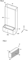
- Fig. 2 is a perspective view of a duct of an induction flow generator in Fig. 1 .
- processing machine 10 further includes an induction flow generator 41.
- Induction flow generator 41 is provided in second wall 25.
- Induction flow generator 41 generates an air flow flowing from below to upward along second wall 25 in processing area 51.
- Induction flow generator 41 includes a first blower 46 and a duct 42.
- First blower 46 allows air to flow into processing area 51 while operating.
- First blower 46 is attached to second wall 25. While operating, first blower 46 allows air to flow from accommodation space 56 into processing area 51.
- Duct 42 has a duct shape and forms a flow path through which air flows.
- Duct 42 is provided in processing area 51.
- Duct 42 is attached to second wall 25.
- Duct 42 feeds the air supplied from first blower 46 into processing area 51 as an air flow flowing from below to upward.
- Duct 42 includes an inlet 44, an upstream portion 42P, a reverse portion 42R, a downstream portion 42Q, and an outlet 43.
- Inlet 44, upstream portion 42P, reverse portion 42R, downstream portion 42Q, and outlet 43 are provided side by side in that order from an upstream side to a downstream side of the air flow in duct 42.
- Inlet 44 is open at one end of duct 42. Inlet 44 is overlapped with an opening 35 (see Fig. 1 ) provided in second wall 25. Accommodation space 56 and a space in duct 42 communicate with each other through opening 35 and inlet 44. First blower 46 is connected to inlet 44.
- Inlet 44 is provided at a position higher than outlet 43 in the Z-axis direction. Inlet 44 is provided at a position higher than first opening 31 in the Z-axis direction. Inlet 44 is provided at a position lower than second opening 33 in the Z-axis direction.
- Upstream portion 42P extends in the Z-axis direction along second wall 25. Upstream portion 42P extends downward from inlet 44. Upstream portion 42P may have a tapered shape such that a flow path area of the air decreases downward.
- Reverse portion 42R is connected to a lower end of upstream portion 42P. Reverse portion 42R is provided so as to be reversed by 180° from upstream portion 42P while being curved in a direction toward first wall 23 in the X-axis direction.
- Downstream portion 42Q is connected to an upper end of reverse portion 42R. Downstream portion 42Q extends upward from reverse portion 42R. A length of downstream portion 42Q in the Z-axis direction is smaller than a length of upstream portion 42P in the Z-axis direction.
- Outlet 43 is open at the other end of duct 42. Outlet 43 is provided at an upper end of downstream portion 42Q.
- Outlet 43 is provided at a position lower than second opening 33.
- An opening surface of outlet 43 faces an opening surface of second opening 33 in the Z-axis direction.
- Outlet 43 may be provided at a position as high as first opening 31 in the Z-axis direction. This case corresponds to a case where the opening surface of outlet 43 is at a height between the upper end and the lower end of the opening surface of first opening 31 (in Fig. 1 , Ha ⁇ h ⁇ Hb). Outlet 43 may be provided at a position lower than first opening 31 in the Z-axis direction. This case corresponds to a case where the opening surface of outlet 43 is at a position lower than the lower end of the opening surface of first opening 31 (in Fig. 1 , h ⁇ Ha).
- Outlet 43 is preferably provided at a position overlapping first opening 31 in a Y-axis direction.
- the air supplied from first blower 46 flows into duct 42 through inlet 44.
- the air flowing into duct 42 flows from above to below through upstream portion 42P.
- the air flow flowing from above to below is reversed to the air flow flowing from below to upward in reverse portion 42R.
- the air is sent into processing area 51 as an air flow flowing from below to upward through outlet 43.
- Processing machine 10 further includes a dust collector 71, a second blower 76, and a dust collecting duct 72.
- Dust collector 71 is provided in the external space of processing area 51. Dust collector 71 is connected to second opening 33 through dust collecting duct 72.
- second blower 76 supplies air from inside of processing area 51 to dust collector 71 through second opening 33.
- Second blower 76 is incorporated in dust collector 71.
- Second blower 76 may be provided in second opening 33 or may be provided on a path of dust collecting duct 72.
- processing machine 10 Next, functions and effects provided by processing machine 10 according to the embodiment will be described.
- the material powder changes into steam, the steam is cooled, and thus fume of fine particulate (for example, particles of less than or equal to 1 ⁇ m) is generated in processing area 51.
- fume of fine particulate for example, particles of less than or equal to 1 ⁇ m
- the material powder may fly in accommodation space 56.
- the fume generated in processing area 51 and the material powder flying in accommodation space 56 are collected in dust collector 71 through dust collecting duct 72.
- induction flow generator 41 generates an air flow flowing from below to upward along second wall 25 (an air flow (induction flow) indicated by an outlined arrow 210 in Fig. 1 ) in processing area 51.
- an air flow along the horizontal direction an air flow indicated by arrow 220 in Fig. 1
- the induction flow an air flow indicated by an arrow 230 in Fig. 1
- the air flowing from first wall 23 toward second wall 25 flows from below to upward by being guided by the induction flow
- the fume generated at the processing point of workpiece W is collected near second wall 25 by the air flow along the horizontal direction from first wall 23 toward second wall 25.
- the fume collected near second wall 25 is further discharged to outside of processing area 51 through second opening 33 by an upward air flow along second wall 25. Therefore, the fume generated in processing area 50 due to the AM processing can be efficiently discharged to outside.
- Second opening 33 is provided in ceiling 27.
- the ceiling is located ahead of the upward air flow along second wall 25, and thus the fume in processing area 51 can be more efficiently discharged through second opening 33.
- outlet 43 is provided at a position as high as first opening 31 or at a position lower than first opening 31, the air flow along the horizontal direction from first wall 23 toward second wall 25 can more reliably collide with the induction flow. As a result, an upward air flow along second wall 25 is likely to occur, and thus the fume in processing area 51 can be more efficiently discharged to outside.
- Induction flow generator 41 generates the induction flow by allowing air to flow into processing area 51 from accommodation space 56 along with the operation of first blower 46.
- the material powder flying in accommodation space 56 is also guided into processing area 51 through duct 42 and then discharged to outside by the induction flow fed from outlet 43.
- induction flow generator 41 not only the fume generated in processing area 51 but also the material powder flying in accommodation space 56 are discharged to outside by induction flow generator 41, and thus a particulate discharge mechanism in processing machine 10 can have a simple configuration.
- Fig. 3 is a perspective view illustrating a modification of the first opening in Fig. 1 .
- processing machine 10 further includes a rectifying mechanism 91.
- Rectifying mechanism 91 is provided with first opening 31. Rectifying mechanism 91 changes the air flowing into processing area 51 into an air flow along the horizontal direction.
- Rectifying mechanism 91 includes a block body 92.
- Block body 92 is provided with a plurality of first openings 31.
- the plurality of first openings 31 is arranged in the vertical direction.
- the first openings 31 extend in a slit shape along the Y-axis direction.
- Fig. 4 is a block diagram related to control of the first blower and the second blower.
- processing machine 10 further includes a control unit 81.
- Control unit 81 is a control panel that is provided in processing machine 10 and controls various operations in processing machine 10.
- Control unit 81 controls first blower 46 and second blower 76.
- Control unit 81 includes a blow controller 82, a storage 83, and a processing controller 84.
- Blow controller 82 controls operations of first blower 46 and second blower 76.
- Storage 83 stores a processing program (numerical control program) created by the user of processing machine 10.
- Processing controller 84 executes the processing program stored in storage 83 in accordance with an instruction from the user.
- Blow controller 82 determines whether the AM processing for the workpiece is performed on the basis of the processing program executed in processing controller 84.
- Material powder supply device 66 further includes a refill detector 85.
- Refill detector 85 detects refilling of the material powder to material powder supply device 66 (material powder tank 67).
- refill detector 85 is provided at the refill port for the material powder in material powder tank 67, and includes a sensor capable of detecting the material powder charged to the refill port.
- refill detector 85 may include a sensor capable of detecting that the lid member is opened.
- blow controller 82 determines whether material powder supply device 66 is refilled with the material powder.
- Control unit 81 operates first blower 46 and second blower 76 while the AM processing for the workpiece is performed. Control unit 81 operates first blower 46 and second blower 76 regardless of whether the material powder is refilled to material powder supply device 66 while the AM processing for the workpiece is performed.
- Control unit 81 operates first blower 46 and stops second blower 76 while the AM processing for the workpiece is not performed and the material powder is refilled to material powder supply device 66.
- first blower 46 is operated to supply air from accommodation space 56 into processing area 51, and thus the material powder flying in accommodation space 56 is fed into processing area 51.
- the material powder flying in accommodation space 56 and the fume generated in processing area 51 are discharged to outside by operating both first blower 46 and second blower 76 discharge. This makes it possible to clean the atmosphere in accommodation space 56 and processing area 51 at an appropriate timing and suppress energy consumption in the blowers.
- processing machine 10 is a processing machine that performs the AM processing for a workpiece with a molten material.
- Processing machine 10 includes first cover 21 having first wall 23 and second wall 25 that face each other in the horizontal direction and forming processing area 51 between first wall 23 and second wall 25.
- First wall 23 is provided with first opening 31 allowing air as a gas to flow into processing area 51.
- Processing machine 10 further includes induction flow generator 41 that generates an air flow flowing from below to upward along second wall 25.
- First cover 21 is provided with second opening 33 that allows air to flow out from processing area 51.
- Processing machine 10 can efficiently discharge particulates (fume) generated due to the AM processing for the workpiece from processing area 51.
- the AM processing performed by the processing machine of the present invention may adopt, for example, a directional energy deposition method in which a wire is fed to a workpiece instead of the material powder in the embodiment.
- the AM processing performed by the processing machine of the present invention may adopt a selective laser melting method or thermal spraying.
- the present invention is applied to a processing machine that performs additive manufacturing processing.
Landscapes
- Engineering & Computer Science (AREA)
- Chemical & Material Sciences (AREA)
- Materials Engineering (AREA)
- Manufacturing & Machinery (AREA)
- Physics & Mathematics (AREA)
- Optics & Photonics (AREA)
- Mechanical Engineering (AREA)
- Plasma & Fusion (AREA)
- Health & Medical Sciences (AREA)
- Environmental & Geological Engineering (AREA)
- Toxicology (AREA)
- Automation & Control Theory (AREA)
- Life Sciences & Earth Sciences (AREA)
- Sustainable Development (AREA)
- Laser Beam Processing (AREA)
- Powder Metallurgy (AREA)
Abstract
Description
- The present invention relates to a processing machine.
- In relation to a conventional processing machine, for example,
WO 2011/49143 - In addition to the above disclosure,
Japanese Patent Laying-Open No. 2012-224919 Japanese Patent Laying-Open No. 2018-127710 Japanese Patent Laying-Open No. 2016-107454 Japanese Patent Laying-Open No. 2016-153529 -
- PTL 1:
WO 2011/49143 - PTL 2:
Japanese Patent Laying-Open No. 2012-224919 - PTL 3:
Japanese Patent Laying-Open No. 2018-127710 - PTL 4:
Japanese Patent Laying-Open No. 2016-107454 - PTL 5:
Japanese Patent Laying-Open No. 2016-153529 - Examples of a method of performing additive manufacturing (AM) processing for a workpiece by a molten material include directed energy deposition (DED), selective laser melting (SLM), thermal spraying, and the like. Use of such methods generates particulates (fume) by the AM processing for the workpiece, and thus the particulates are required to be discharged from the processing area efficiently.
- Meanwhile, in the apparatus manufacturing a three-dimensional shaped object disclosed in PTL 1, it is attempted to discharge fume by forming a local gas flow in the chamber and accompanying the fume with the gas flow. However, since the fume generated at a processing point of the powder sintering lamination is widely diffused in the chamber, it is difficult to efficiently discharge the fume by the local gas flow in the chamber.
- Therefore, an object of the present invention is to solve the above problem, and to provide a processing machine capable of efficiently discharging particulates generated by additive manufacturing processing for a workpiece from a processing area.
- A processing machine according to the present invention is a processing machine that performs additive manufacturing processing for a workpiece with a molten material. The processing machine includes a first cover having a first wall and a second wall that face each other in a horizontal direction and forming a processing area between the first wall and the second wall. The first wall is provided with a first opening allowing a gas to flow into the processing area. The processing machine further includes an induction flow generator that generates a gas flow flowing from below to upward along the second wall. The first cover is provided with a second opening allowing the gas to flow out from the processing area.
- The processing machine configured as described above can generate a gas flow flowing from below to upward along the second wall (hereinafter, referred to as "induction flow") by the induction flow generator. As a result, a gas flow along the horizontal direction that the gas flowing into the processing area through the first opening flows from the first wall provided with the first opening toward the second wall through which the induction flow flows, and an upward gas flow that the gas flowing from the first wall toward the second wall flows from below to upward by being guided by the induction flow can be generated in the processing area. The particulates generated in the processing area due to the AM processing are carried by this gas flow and is discharged to outside through the second opening, and thus the particulates can be efficiently discharged.
- The processing machine preferably further includes a second cover that forms an accommodation space and accommodates, in the accommodation space, a material powder supply device that supplies the material powder toward the processing area. The induction flow generator includes a first blower that supplies a gas from the accommodation space into the processing area, and a duct that feeds the gas supplied from the accommodation space into the processing area as a gas flow flowing from below to upward.
- In the processing machine configured as described above, by operating the first blower, the particulates generated in the accommodation space can also be carried by the induction flow and discharged to outside. Therefore, the particulates can be discharged from both the processing area and the accommodation space with a simple configuration.
- The processing machine preferably further includes a dust collector, a second blower that supplies a gas from the processing area to the dust collector through the second opening, and a control unit that controls the first blower and the second blower. The control unit operates the first blower and the second blower while the AM processing for the workpiece is performed, and operates the first blower and stops the second blower while the additional manufacturing processing for the workpiece is not performed and the material powder is refilled to the material powder supply device.
- In the processing machine configured as described above, the first blower and the second blower are selectively operated in accordance with timing at which particulates are generated in each of the processing area and the accommodation space. This makes it possible to discharge the particulates from the processing area and the accommodation space while suppressing energy consumption in the blower.
- The first cover preferably further includes a ceiling. The second opening is provided in the ceiling.
- In the processing machine configured as described above, since the ceiling is located ahead of the induction flow flowing from below to upward, the particulates can be more efficiently discharged to outside through the second opening.
- The induction flow generator preferably includes a duct having an outlet and feeding a gas into the processing area through the outlet. The outlet is provided at a position as high as the first opening or at a position lower than the first opening.
- The processing machine configured as described above can allow the gas flowing from the first wall toward the second wall to collide with the induction flow more reliably. This facilitates generation of an upward gas flow flowing from below to upward, and thus the particulates can be more efficiently discharged to outside.
- The processing machine preferably further includes a rectifying mechanism that is provided with the first opening and changes a gas flowing into the processing area into a gas flow along the horizontal direction.
- In the processing machine configured as described above, since the gas flowing into the processing area through the first opening easily reaches the induction flow, the particulates can be more efficiently discharged to outside.
- As described above, in accordance with the present invention, it is possible to provide the processing machine capable of efficiently discharging particulates generated by the AM processing for a workpiece from the processing area.
-
-
Fig. 1 is a front view of a processing machine according to an embodiment of the present invention. -
Fig. 2 is a perspective view of a duct of an induction flow generator inFig. 1 . -
Fig. 3 is a perspective view illustrating a modification of a first opening inFig. 1 . -
Fig. 4 is a block diagram related to control of a first blower and a second blower. - An embodiment of the present invention will be described with reference to the drawings. In the drawings referred to below, the same or corresponding members are denoted by the same reference signs.
-
Fig. 1 is a front view of a processing machine according to the embodiment of the present invention.Fig. 1 illustrates an inner side of the processing machine in transparent view of a front surface of a cover having appearance of the processing machine. - Referring to
Fig. 1 , aprocessing machine 10 is a processing machine capable of performing additive manufacturing (AM) processing for a workpiece with a molten material. The AM processing refers to a processing method of creating a three-dimensional shape on a workpiece by attaching a material, and a mass of the workpiece increases after the AM processing as compared with before the AM processing. -
Processing machine 10 is a numerical control (NC) processing machine in which various operations for workpiece processing are automated by numerical control by a computer. -
Processing machine 10 may be a processing machine capable of only the AM processing for a workpiece, or may be an AM/SM hybrid processing machine capable of the AM processing for a workpiece and subtractive manufacturing (SM) processing for a workpiece. -
Processing machine 10 includes afirst cover 21, aprocessing head 14, and aworkpiece moving stage 12. -
First cover 21 forms aprocessing area 51 for performing the AM processing on a workpiece W. -
Processing head 14 is provided inprocessing area 51. A laser beam and a material powder are introduced intoprocessing head 14.Processing head 14 includes a nozzle for discharging the material powder and a laser beam irradiation device for irradiating workpiece W with the laser beam (not illustrated).Processing head 14 performs the AM processing on workpiece W by discharging the material powder and irradiating workpiece W with the laser light (directed energy deposition (DED)). -
Workpiece moving stage 12 is provided inprocessing area 51.Workpiece moving stage 12faces processing head 14 in a Z-axis direction parallel to a vertical direction.Workpiece moving stage 12 is provided belowprocessing head 14.Workpiece moving stage 12 has aplacement surface 12a.Placement surface 12a is formed of a plane (referred to as an "X-axis-Y-axis plane") including an X-axis parallel to a horizontal direction and a Y-axis parallel to the horizontal direction and orthogonal to the X-axis. Workpiece W is placed onplacement surface 12a.Workpiece moving stage 12 is configured to be able to hold workpiece W placed onplacement surface 12a. -
Workpiece moving stage 12 moves workpiece W in the X-axis-Y-axis plane by various feeding mechanisms, guide mechanisms, a servomotor, and the like. By movingworkpiece moving stage 12, a processing point of the AM processing on workpiece W can be moved. - In a configuration where
processing head 14 irradiating workpiece W with the laser light and supplying the material powder, andworkpiece moving stage 12 holding workpiece W are mutually moved, the processing point of the AM processing on workpiece W can be moved. For example,processing head 14 may move in air inprocessing area 51, or this configuration may be combined withworkpiece moving stage 12. - Processing
machine 10 further includes asecond cover 61 and a materialpowder supply device 66. -
Second cover 61 is provided side by side withfirst cover 21.Second cover 61 forms anaccommodation space 56. Processingarea 51 andaccommodation space 56 are arranged in an X-axis direction. - Material
powder supply device 66 is accommodated inaccommodation space 56. Materialpowder supply device 66 supplies the material powder used for the AM processing towardprocessing head 14. Materialpowder supply device 66 includes amaterial powder tank 67 and amixer 68.Material powder tank 67 has a tank shape and stores the material powder used for the AM processing.Mixer 68 is provided belowmaterial powder tank 67.Mixer 68 is configured to be able to mix the material powder and carrier gas. -
Material powder tank 67 is provided with a refill port (not illustrated) used for refilling the material powder into the tank. A height from a floor surface on which processingmachine 10 is installed to the refill port may be, for example, greater than or equal to 1.2 m, or greater than or equal to 1.5 m. - In addition to material
powder supply device 66, a laser oscillator (not illustrated) that oscillates the laser beam used for the AM processing may be accommodated inaccommodation space 56. -
First cover 21 includes afirst wall 23, asecond wall 25, and aceiling 27.First wall 23 andsecond wall 25 face each other in the X-axis direction.First wall 23 andsecond wall 25 are provided apart from each other in the X-axis direction.First wall 23 andsecond wall 25 have a flat plate shape parallel to a Y-axis-Z-axis plane. Processingarea 51 is formed betweenfirst wall 23 andsecond wall 25. -
Ceiling 27 is provided at a top of processingarea 51.Ceiling 27 is connected to an upper end offirst wall 23 and an upper end ofsecond wall 25. - As a typical example,
first cover 21 further includes an openable and closable door (not illustrated). The door is provided on a front surface offirst cover 21 on a front side (transparent inFig. 1 ) on the sheet illustratingFig. 1 . The door is provided on the front surface offirst cover 21, different fromfirst wall 23 andsecond wall 25. The door is closed when processinghead 14 is performing the AM processing on workpiece W, and the door is opened when a user needs to accessprocessing area 51 to attach or detach workpiece W to or fromworkpiece moving stage 12, or the like. -
Second wall 25 is located betweenprocessing area 51 andaccommodation space 56 in the X-axis direction. Processingarea 51 andaccommodation space 56 are separated bysecond wall 25. -
First wall 23 is provided with afirst opening 31. First opening 31 is an opening allowing air to flow intoprocessing area 51. First opening 31 is formed of a through hole penetrating first cover 21 (first wall 23). Processingarea 51 and an external space (for example, an indoor space such as a factory where processingmachine 10 is installed) outsideprocessing area 51 communicate with each other throughfirst opening 31. - First opening 31 is provided at a position above and away from the floor surface on which processing
machine 10 is installed. First opening 31 is provided at a position higher thanplacement surface 12a ofworkpiece moving stage 12 in the Z-axis direction (corresponding to a case whereplacement surface 12a is at a position lower than a lower end of an opening surface of first opening 31). - Without limited to the above configuration,
first opening 31 may be provided at a position as high asplacement surface 12a ofworkpiece moving stage 12 in the Z-axis direction (corresponding to a case whereplacement surface 12a is at a height between an upper end and the lower end of the opening surface of first opening 31). First opening 31 may be provided at a position lower thanplacement surface 12a ofworkpiece moving stage 12 in the Z-axis direction (corresponding to a case whereplacement surface 12a is at a position higher than the upper end of the opening surface of first opening 31). - First opening 31 may have another application (an application of discharging chips to outside of the machine, for example, in a case where processing
machine 10 is an AM/SM hybrid processing machine) in addition to an application of allowing air to flow intoprocessing area 51. - First opening 31 may be provided with a blower allowing air to flow into
processing area 51 forcibly. -
First cover 21 is further provided with asecond opening 33.Second opening 33 is an opening allowing air to flow out from processingarea 51.Second opening 33 is formed of a through hole penetratingfirst cover 21. -
Second opening 33 is provided at a position higher thanfirst opening 31 in the Z-axis direction.Second opening 33 is provided at a position higher than processinghead 14 andworkpiece moving stage 12 in the Z-axis direction.Second opening 33 is provided at a position apart fromfirst wall 23 andsecond wall 25 in the X-axis direction.Second opening 33 is provided at a position closer tosecond wall 25 thanfirst wall 23 in the X-axis direction (distance fromsecond wall 25 tosecond opening 33 in the X-axis direction < distance fromfirst wall 23 tosecond opening 33 in the X-axis direction). -
Second opening 33 is provided inceiling 27.Second opening 33 is formed of a throughhole penetrating ceiling 27. - An opening area of
second opening 33 may be larger than an opening area offirst opening 31, or may be smaller than or equal to the opening area offirst opening 31. -
Fig. 2 is a perspective view of a duct of an induction flow generator inFig. 1 . Referring toFigs. 1 and2 , processingmachine 10 further includes aninduction flow generator 41.Induction flow generator 41 is provided insecond wall 25.Induction flow generator 41 generates an air flow flowing from below to upward alongsecond wall 25 inprocessing area 51. -
Induction flow generator 41 includes afirst blower 46 and aduct 42.First blower 46 allows air to flow intoprocessing area 51 while operating.First blower 46 is attached tosecond wall 25. While operating,first blower 46 allows air to flow fromaccommodation space 56 intoprocessing area 51. -
Duct 42 has a duct shape and forms a flow path through which air flows.Duct 42 is provided inprocessing area 51.Duct 42 is attached tosecond wall 25.Duct 42 feeds the air supplied fromfirst blower 46 intoprocessing area 51 as an air flow flowing from below to upward. -
Duct 42 includes aninlet 44, anupstream portion 42P, areverse portion 42R, adownstream portion 42Q, and anoutlet 43.Inlet 44,upstream portion 42P,reverse portion 42R,downstream portion 42Q, andoutlet 43 are provided side by side in that order from an upstream side to a downstream side of the air flow induct 42. -
Inlet 44 is open at one end ofduct 42.Inlet 44 is overlapped with an opening 35 (seeFig. 1 ) provided insecond wall 25.Accommodation space 56 and a space induct 42 communicate with each other throughopening 35 andinlet 44.First blower 46 is connected toinlet 44. -
Inlet 44 is provided at a position higher thanoutlet 43 in the Z-axis direction.Inlet 44 is provided at a position higher thanfirst opening 31 in the Z-axis direction.Inlet 44 is provided at a position lower thansecond opening 33 in the Z-axis direction. -
Upstream portion 42P extends in the Z-axis direction alongsecond wall 25.Upstream portion 42P extends downward frominlet 44.Upstream portion 42P may have a tapered shape such that a flow path area of the air decreases downward.Reverse portion 42R is connected to a lower end ofupstream portion 42P.Reverse portion 42R is provided so as to be reversed by 180° fromupstream portion 42P while being curved in a direction towardfirst wall 23 in the X-axis direction.Downstream portion 42Q is connected to an upper end ofreverse portion 42R.Downstream portion 42Q extends upward fromreverse portion 42R. A length ofdownstream portion 42Q in the Z-axis direction is smaller than a length ofupstream portion 42P in the Z-axis direction. -
Outlet 43 is open at the other end ofduct 42.Outlet 43 is provided at an upper end ofdownstream portion 42Q. -
Outlet 43 is provided at a position lower thansecond opening 33. An opening surface ofoutlet 43 faces an opening surface ofsecond opening 33 in the Z-axis direction. -
Outlet 43 may be provided at a position as high asfirst opening 31 in the Z-axis direction. This case corresponds to a case where the opening surface ofoutlet 43 is at a height between the upper end and the lower end of the opening surface of first opening 31 (inFig. 1 , Ha ≤ h ≤ Hb).Outlet 43 may be provided at a position lower thanfirst opening 31 in the Z-axis direction. This case corresponds to a case where the opening surface ofoutlet 43 is at a position lower than the lower end of the opening surface of first opening 31 (inFig. 1 , h < Ha). -
Outlet 43 is preferably provided at a position overlappingfirst opening 31 in a Y-axis direction. - The air supplied from
first blower 46 flows intoduct 42 throughinlet 44. The air flowing intoduct 42 flows from above to below throughupstream portion 42P. The air flow flowing from above to below is reversed to the air flow flowing from below to upward inreverse portion 42R. After flowing from below to above indownstream portion 42Q, the air is sent intoprocessing area 51 as an air flow flowing from below to upward throughoutlet 43. - Processing
machine 10 further includes adust collector 71, asecond blower 76, and adust collecting duct 72. -
Dust collector 71 is provided in the external space ofprocessing area 51.Dust collector 71 is connected tosecond opening 33 throughdust collecting duct 72. - While operating,
second blower 76 supplies air from inside ofprocessing area 51 todust collector 71 throughsecond opening 33.Second blower 76 is incorporated indust collector 71.Second blower 76 may be provided insecond opening 33 or may be provided on a path ofdust collecting duct 72. - Next, functions and effects provided by processing
machine 10 according to the embodiment will be described. - At the processing point of workpiece W, the material powder changes into steam, the steam is cooled, and thus fume of fine particulate (for example, particles of less than or equal to 1 µm) is generated in
processing area 51. Further, when the material powder is refilled to material powder supply device 66 (material powder tank 67), the material powder (for example, powder of about 50 µm) may fly inaccommodation space 56. These particulates are required to be efficiently discharged from inside ofprocessing area 51 or inside ofaccommodation space 56 for health reasons of the user or the like. - Therefore, in processing
machine 10 according to the embodiment, the fume generated inprocessing area 51 and the material powder flying inaccommodation space 56 are collected indust collector 71 throughdust collecting duct 72. - Here,
induction flow generator 41 generates an air flow flowing from below to upward along second wall 25 (an air flow (induction flow) indicated by an outlinedarrow 210 inFig. 1 ) inprocessing area 51. As a result, an air flow along the horizontal direction (an air flow indicated byarrow 220 inFig. 1 ) that the air flowing intoprocessing area 51 throughfirst opening 31 flows fromfirst wall 23 provided withfirst opening 31 towardsecond wall 25 through which the induction flow (an air flow indicated by anarrow 230 inFig. 1 ) that the air flowing fromfirst wall 23 towardsecond wall 25 flows from below to upward by being guided by the induction flow can be generated. - The fume generated at the processing point of workpiece W is collected near
second wall 25 by the air flow along the horizontal direction fromfirst wall 23 towardsecond wall 25. The fume collected nearsecond wall 25 is further discharged to outside ofprocessing area 51 throughsecond opening 33 by an upward air flow alongsecond wall 25. Therefore, the fume generated in processing area 50 due to the AM processing can be efficiently discharged to outside. -
Second opening 33 is provided inceiling 27. In this configuration, the ceiling is located ahead of the upward air flow alongsecond wall 25, and thus the fume inprocessing area 51 can be more efficiently discharged throughsecond opening 33. - Further, in a case where
outlet 43 is provided at a position as high asfirst opening 31 or at a position lower thanfirst opening 31, the air flow along the horizontal direction fromfirst wall 23 towardsecond wall 25 can more reliably collide with the induction flow. As a result, an upward air flow alongsecond wall 25 is likely to occur, and thus the fume inprocessing area 51 can be more efficiently discharged to outside. -
Induction flow generator 41 generates the induction flow by allowing air to flow intoprocessing area 51 fromaccommodation space 56 along with the operation offirst blower 46. Thus, the material powder flying inaccommodation space 56 is also guided intoprocessing area 51 throughduct 42 and then discharged to outside by the induction flow fed fromoutlet 43. As a result, not only the fume generated inprocessing area 51 but also the material powder flying inaccommodation space 56 are discharged to outside byinduction flow generator 41, and thus a particulate discharge mechanism in processingmachine 10 can have a simple configuration. -
Fig. 3 is a perspective view illustrating a modification of the first opening inFig. 1 . Referring toFigs. 1 and3 , in the modification, processingmachine 10 further includes arectifying mechanism 91. Rectifyingmechanism 91 is provided withfirst opening 31. Rectifyingmechanism 91 changes the air flowing intoprocessing area 51 into an air flow along the horizontal direction. - Rectifying
mechanism 91 includes ablock body 92.Block body 92 is provided with a plurality offirst openings 31. The plurality offirst openings 31 is arranged in the vertical direction. Thefirst openings 31 extend in a slit shape along the Y-axis direction. - In this configuration, the air flowing into
processing area 51 throughfirst opening 31 easily reaches the induction flow alongsecond wall 25, and thus the particulates can be more efficiently discharged to outside. -
Fig. 4 is a block diagram related to control of the first blower and the second blower. Referring toFigs. 1 and4 , processingmachine 10 further includes acontrol unit 81.Control unit 81 is a control panel that is provided in processingmachine 10 and controls various operations in processingmachine 10.Control unit 81 controlsfirst blower 46 andsecond blower 76. -
Control unit 81 includes ablow controller 82, astorage 83, and aprocessing controller 84.Blow controller 82 controls operations offirst blower 46 andsecond blower 76.Storage 83 stores a processing program (numerical control program) created by the user of processingmachine 10.Processing controller 84 executes the processing program stored instorage 83 in accordance with an instruction from the user. -
Blow controller 82 determines whether the AM processing for the workpiece is performed on the basis of the processing program executed in processingcontroller 84. - Material
powder supply device 66 further includes arefill detector 85.Refill detector 85 detects refilling of the material powder to material powder supply device 66 (material powder tank 67). For example,refill detector 85 is provided at the refill port for the material powder inmaterial powder tank 67, and includes a sensor capable of detecting the material powder charged to the refill port. - An openable and closable lid member is provided in the refill port of
material powder tank 67. In this case,refill detector 85 may include a sensor capable of detecting that the lid member is opened. - Upon receipt of a signal from
refill detector 85,blow controller 82 determines whether materialpowder supply device 66 is refilled with the material powder. -
Control unit 81 operatesfirst blower 46 andsecond blower 76 while the AM processing for the workpiece is performed.Control unit 81 operatesfirst blower 46 andsecond blower 76 regardless of whether the material powder is refilled to materialpowder supply device 66 while the AM processing for the workpiece is performed. -
Control unit 81 operatesfirst blower 46 and stopssecond blower 76 while the AM processing for the workpiece is not performed and the material powder is refilled to materialpowder supply device 66. - While the AM processing for the workpiece is not performed and the material powder is refilled to material
powder supply device 66, onlyfirst blower 46 is operated to supply air fromaccommodation space 56 intoprocessing area 51, and thus the material powder flying inaccommodation space 56 is fed intoprocessing area 51. When the AM processing for the workpiece is performed, the material powder flying inaccommodation space 56 and the fume generated inprocessing area 51 are discharged to outside by operating bothfirst blower 46 andsecond blower 76 discharge. This makes it possible to clean the atmosphere inaccommodation space 56 andprocessing area 51 at an appropriate timing and suppress energy consumption in the blowers. - To summarize a structure of processing
machine 10 according to the embodiment of the present invention described above, processingmachine 10 according to the embodiment is a processing machine that performs the AM processing for a workpiece with a molten material. Processingmachine 10 includesfirst cover 21 havingfirst wall 23 andsecond wall 25 that face each other in the horizontal direction and formingprocessing area 51 betweenfirst wall 23 andsecond wall 25.First wall 23 is provided withfirst opening 31 allowing air as a gas to flow intoprocessing area 51. Processingmachine 10 further includesinduction flow generator 41 that generates an air flow flowing from below to upward alongsecond wall 25.First cover 21 is provided withsecond opening 33 that allows air to flow out from processingarea 51. - Processing
machine 10 according to the embodiment of the present invention configured as described above can efficiently discharge particulates (fume) generated due to the AM processing for the workpiece from processingarea 51. - The AM processing performed by the processing machine of the present invention may adopt, for example, a directional energy deposition method in which a wire is fed to a workpiece instead of the material powder in the embodiment. The AM processing performed by the processing machine of the present invention may adopt a selective laser melting method or thermal spraying.
- It should be understood that the embodiment disclosed herein is illustrative in all respects and not restrictive. The scope of the present invention is defined not by the above description but by the claims, and is intended to include meanings equivalent to the claims and all modifications within the scope.
- The present invention is applied to a processing machine that performs additive manufacturing processing.
- 10: processing machine, 12: workpiece moving stage, 12a: placement surface, 14: processing head, 21: first cover, 23: first wall, 25: second wall, 27: ceiling, 31: first opening, 33: second opening, 41: induction flow generator, 42: duct, 42p: upstream portion, 42q: downstream portion, 42r: reverse portion, 43: outlet, 44: inlet, 46: first blower, 51: processing area, 56: accommodation space, 61: second cover, 66: material powder supply device, 67: material powder tank, 68: mixer, 71: dust collector, 72: dust collecting duct, 76: second blower, 81: control unit, 82: blow controller, 83: storage, 84: processing controller, 85: refill detector, 91: rectifying mechanism, 92: block body
Claims (6)
- A processing machine that performs additive manufacturing processing for a workpiece with a molten material, the processing machine comprising:a first cover having a first wall and a second wall that face each other in a horizontal direction and defining a processing area between the first wall and the second wall,the first wall being provided with a first opening allowing a gas to flow into the processing area; the processing machine further comprisingan induction flow generator that generates a gas flow flowing from below to upward along the second wall,the first cover being provided with a second opening allowing the gas to flow out from the processing area.
- The processing machine according to claim 1, further comprising a second cover defining an accommodation space and accommodating, in the accommodation space, a material powder supply device that supplies a material powder toward the processing area,wherein the induction flow generator includesa first blower that supplies a gas from the accommodation space into the processing area, anda duct that feeds a gas supplied from the accommodation space into the processing area as a gas flow flowing from below to upward.
- The processing machine according to claim 2, further comprising:a dust collector;a second blower that supplies a gas from the processing area to the dust collector through the second opening; anda control unit that controls the first blower and the second blower,wherein the control unitoperates the first blower and the second blower while the additive manufacturing processing for the workpiece is performed, andoperates the first blower and stops the second blower while the additive manufacturing processing for the workpiece is not performed and the material powder is refilled to the material powder supply device.
- The processing machine according to any one of claims 1 to 3, whereinthe first cover further includes a ceiling, andthe second opening is provided in the ceiling.
- The processing machine according to any one of claims 1 to 4, whereinthe induction flow generator includes a duct having an outlet and feeding a gas into the processing area through the outlet, andthe outlet is provided at a position as high as the first opening or at a position lower than the first opening.
- The processing machine according to any one of claims 1 to 5, further comprising a rectifying mechanism that is provided with the first opening and changes the gas flowing into the processing area into a gas flow along the horizontal direction.
Applications Claiming Priority (2)
| Application Number | Priority Date | Filing Date | Title |
|---|---|---|---|
| JP2019091991A JP6745945B1 (en) | 2019-05-15 | 2019-05-15 | Processing machine |
| PCT/JP2020/019229 WO2020230843A1 (en) | 2019-05-15 | 2020-05-14 | Processing machine |
Publications (3)
| Publication Number | Publication Date |
|---|---|
| EP3960333A1 true EP3960333A1 (en) | 2022-03-02 |
| EP3960333A4 EP3960333A4 (en) | 2023-07-12 |
| EP3960333B1 EP3960333B1 (en) | 2025-08-06 |
Family
ID=72146144
Family Applications (1)
| Application Number | Title | Priority Date | Filing Date |
|---|---|---|---|
| EP20806272.9A Active EP3960333B1 (en) | 2019-05-15 | 2020-05-14 | Processing machine |
Country Status (5)
| Country | Link |
|---|---|
| US (1) | US12454101B2 (en) |
| EP (1) | EP3960333B1 (en) |
| JP (1) | JP6745945B1 (en) |
| CN (1) | CN113853264B (en) |
| WO (1) | WO2020230843A1 (en) |
Families Citing this family (1)
| Publication number | Priority date | Publication date | Assignee | Title |
|---|---|---|---|---|
| EP4263092A4 (en) * | 2020-12-16 | 2024-11-27 | PostProcess Technologies Inc. | EXHAUST SYSTEM FOR A CARRIER REMOVAL DEVICE |
Family Cites Families (17)
| Publication number | Priority date | Publication date | Assignee | Title |
|---|---|---|---|---|
| JP2008100232A (en) * | 2006-10-17 | 2008-05-01 | Toppan Printing Co Ltd | Method and apparatus for collecting scattered matter in laser processing machine or plasma processing machine |
| WO2011049143A1 (en) | 2009-10-21 | 2011-04-28 | パナソニック電工株式会社 | Process for producing three-dimensionally shaped object and device for producing same |
| JP5764751B2 (en) | 2011-04-20 | 2015-08-19 | パナソニックIpマネジメント株式会社 | Manufacturing method and manufacturing apparatus for three-dimensional shaped object |
| JP2016107454A (en) | 2014-12-04 | 2016-06-20 | ローランドディー.ジー.株式会社 | Three-dimensional molding apparatus |
| JP5937249B1 (en) * | 2015-03-20 | 2016-06-22 | Dmg森精機株式会社 | Processing machine |
| JP5937713B1 (en) * | 2015-03-20 | 2016-06-22 | Dmg森精機株式会社 | Processing machine |
| JP5940712B1 (en) * | 2015-05-25 | 2016-06-29 | Dmg森精機株式会社 | Processing machine |
| JP6767007B2 (en) * | 2015-11-20 | 2020-10-14 | 株式会社写真化学 | Stereolithography equipment |
| JP6109987B2 (en) | 2016-03-16 | 2017-04-05 | 株式会社東芝 | Nozzle for additive manufacturing apparatus and additive manufacturing apparatus |
| WO2018033973A1 (en) * | 2016-08-17 | 2018-02-22 | ヤマザキマザック株式会社 | Composite machining device and composite machining method |
| FR3057479B1 (en) * | 2016-10-13 | 2020-07-17 | Addup | MOBILE MULTI-SPEAKER ADDITIVE MANUFACTURING WORKSHOP |
| JP6188103B1 (en) * | 2016-11-16 | 2017-08-30 | 株式会社ソディック | Additive manufacturing equipment |
| JP6898746B2 (en) | 2017-02-10 | 2021-07-07 | 三菱重工業株式会社 | Three-dimensional laminated modeling device, its control method, and beam scanning pattern generation program |
| US10449696B2 (en) * | 2017-03-28 | 2019-10-22 | Velo3D, Inc. | Material manipulation in three-dimensional printing |
| JP2018027612A (en) | 2017-05-22 | 2018-02-22 | ヤマザキマザック株式会社 | Composite machining apparatus |
| US20190099943A1 (en) | 2017-10-03 | 2019-04-04 | General Electric Company | Additive manufacturing method and apparatus |
| JP6410912B1 (en) * | 2017-11-16 | 2018-10-24 | 株式会社ソディック | Additive manufacturing equipment |
-
2019
- 2019-05-15 JP JP2019091991A patent/JP6745945B1/en active Active
-
2020
- 2020-05-14 EP EP20806272.9A patent/EP3960333B1/en active Active
- 2020-05-14 WO PCT/JP2020/019229 patent/WO2020230843A1/en not_active Ceased
- 2020-05-14 CN CN202080035386.3A patent/CN113853264B/en active Active
- 2020-05-14 US US17/611,120 patent/US12454101B2/en active Active
Also Published As
| Publication number | Publication date |
|---|---|
| CN113853264A (en) | 2021-12-28 |
| US12454101B2 (en) | 2025-10-28 |
| JP6745945B1 (en) | 2020-08-26 |
| EP3960333A4 (en) | 2023-07-12 |
| WO2020230843A1 (en) | 2020-11-19 |
| CN113853264B (en) | 2024-03-08 |
| JP2020185594A (en) | 2020-11-19 |
| EP3960333B1 (en) | 2025-08-06 |
| US20220219398A1 (en) | 2022-07-14 |
Similar Documents
| Publication | Publication Date | Title |
|---|---|---|
| CN112888552B (en) | Additive manufacturing system including spacer deflector and method of operating the same | |
| CN103906597B (en) | Laser cutting method and laser cutting device | |
| EP0250596A1 (en) | Clean room | |
| EP3960333B1 (en) | Processing machine | |
| KR102329564B1 (en) | Laser machining device for machining workpieces by means of a laser | |
| CN108435747A (en) | Vent cabinet | |
| EP2990129A1 (en) | Sorting device for material and sorting method | |
| CN108067616B (en) | Styling apparatus is laminated | |
| JP6200351B2 (en) | Dust collector in welding room | |
| EP3134684A1 (en) | A cooking oven with an oven cavity and an oven door | |
| EP3862168A1 (en) | Ejection apparatus, molding apparatus, and method for manufacturing molded body | |
| CN108613201A (en) | Plasma wash mill with barrier rib | |
| EP3826799A1 (en) | Suction device, laser processing machine, and method for suctioning | |
| KR20250000561U (en) | Air Suspension Laser Cutting Machine | |
| US20210138554A1 (en) | Manufacturing device and method for additive manufacturing with movable gas flow supply | |
| CN111788009B (en) | Thermal spray cabin with suction system | |
| WO2021235336A1 (en) | Laser processing machine | |
| JP2020532448A (en) | Equipment and methods for manufacturing large workpieces using movable manufacturing units | |
| CN116323218A (en) | Buffer room and AM system with buffer room | |
| CN112827991A (en) | Fume hood with supplemental air structure | |
| JP3326306B2 (en) | Draft chamber | |
| US20210101186A1 (en) | Air knife systems | |
| WO2013169883A1 (en) | Thermal spray apparatus in a spray booth comprising a safety interlock | |
| KR20140084286A (en) | Substrate processing device and robot controller | |
| EP3766606A1 (en) | Waste product removal systems |
Legal Events
| Date | Code | Title | Description |
|---|---|---|---|
| STAA | Information on the status of an ep patent application or granted ep patent |
Free format text: STATUS: THE INTERNATIONAL PUBLICATION HAS BEEN MADE |
|
| PUAI | Public reference made under article 153(3) epc to a published international application that has entered the european phase |
Free format text: ORIGINAL CODE: 0009012 |
|
| STAA | Information on the status of an ep patent application or granted ep patent |
Free format text: STATUS: REQUEST FOR EXAMINATION WAS MADE |
|
| 17P | Request for examination filed |
Effective date: 20211119 |
|
| AK | Designated contracting states |
Kind code of ref document: A1 Designated state(s): AL AT BE BG CH CY CZ DE DK EE ES FI FR GB GR HR HU IE IS IT LI LT LU LV MC MK MT NL NO PL PT RO RS SE SI SK SM TR |
|
| DAV | Request for validation of the european patent (deleted) | ||
| DAX | Request for extension of the european patent (deleted) | ||
| RIN1 | Information on inventor provided before grant (corrected) |
Inventor name: SHIRATSUKAYAMA, YASUMITSU Inventor name: NISHI, SYUICHI |
|
| A4 | Supplementary search report drawn up and despatched |
Effective date: 20230609 |
|
| RIC1 | Information provided on ipc code assigned before grant |
Ipc: B22F 12/82 20210101ALI20230602BHEP Ipc: B22F 12/00 20210101ALI20230602BHEP Ipc: B29C 64/357 20170101ALI20230602BHEP Ipc: B23K 26/342 20140101ALI20230602BHEP Ipc: B22F 12/70 20210101ALI20230602BHEP Ipc: B22F 10/28 20210101ALI20230602BHEP Ipc: B22F 10/25 20210101ALI20230602BHEP Ipc: B22F 10/322 20210101ALI20230602BHEP Ipc: B29C 64/364 20170101ALI20230602BHEP Ipc: B29C 64/25 20170101ALI20230602BHEP Ipc: B29C 64/153 20170101ALI20230602BHEP Ipc: B33Y 50/02 20150101ALI20230602BHEP Ipc: B33Y 30/00 20150101ALI20230602BHEP Ipc: B23K 26/34 20140101ALI20230602BHEP Ipc: B23K 26/21 20140101ALI20230602BHEP Ipc: B23K 26/16 20060101ALI20230602BHEP Ipc: B22F 3/16 20060101ALI20230602BHEP Ipc: B22F 3/105 20060101AFI20230602BHEP |
|
| GRAP | Despatch of communication of intention to grant a patent |
Free format text: ORIGINAL CODE: EPIDOSNIGR1 |
|
| STAA | Information on the status of an ep patent application or granted ep patent |
Free format text: STATUS: GRANT OF PATENT IS INTENDED |
|
| INTG | Intention to grant announced |
Effective date: 20250402 |
|
| P01 | Opt-out of the competence of the unified patent court (upc) registered |
Free format text: CASE NUMBER: APP_21570/2025 Effective date: 20250507 |
|
| GRAS | Grant fee paid |
Free format text: ORIGINAL CODE: EPIDOSNIGR3 |
|
| GRAA | (expected) grant |
Free format text: ORIGINAL CODE: 0009210 |
|
| STAA | Information on the status of an ep patent application or granted ep patent |
Free format text: STATUS: THE PATENT HAS BEEN GRANTED |
|
| AK | Designated contracting states |
Kind code of ref document: B1 Designated state(s): AL AT BE BG CH CY CZ DE DK EE ES FI FR GB GR HR HU IE IS IT LI LT LU LV MC MK MT NL NO PL PT RO RS SE SI SK SM TR |
|
| REG | Reference to a national code |
Ref country code: GB Ref legal event code: FG4D |
|
| REG | Reference to a national code |
Ref country code: CH Ref legal event code: EP |
|
| REG | Reference to a national code |
Ref country code: DE Ref legal event code: R096 Ref document number: 602020056055 Country of ref document: DE |
|
| REG | Reference to a national code |
Ref country code: IE Ref legal event code: FG4D |
|
| REG | Reference to a national code |
Ref country code: NL Ref legal event code: MP Effective date: 20250806 |
|
| PG25 | Lapsed in a contracting state [announced via postgrant information from national office to epo] |
Ref country code: IS Free format text: LAPSE BECAUSE OF FAILURE TO SUBMIT A TRANSLATION OF THE DESCRIPTION OR TO PAY THE FEE WITHIN THE PRESCRIBED TIME-LIMIT Effective date: 20251206 |
|
| PG25 | Lapsed in a contracting state [announced via postgrant information from national office to epo] |
Ref country code: NO Free format text: LAPSE BECAUSE OF FAILURE TO SUBMIT A TRANSLATION OF THE DESCRIPTION OR TO PAY THE FEE WITHIN THE PRESCRIBED TIME-LIMIT Effective date: 20251106 |
|
| REG | Reference to a national code |
Ref country code: LT Ref legal event code: MG9D |
|
| PG25 | Lapsed in a contracting state [announced via postgrant information from national office to epo] |
Ref country code: PT Free format text: LAPSE BECAUSE OF FAILURE TO SUBMIT A TRANSLATION OF THE DESCRIPTION OR TO PAY THE FEE WITHIN THE PRESCRIBED TIME-LIMIT Effective date: 20251209 |
|
| PG25 | Lapsed in a contracting state [announced via postgrant information from national office to epo] |
Ref country code: FI Free format text: LAPSE BECAUSE OF FAILURE TO SUBMIT A TRANSLATION OF THE DESCRIPTION OR TO PAY THE FEE WITHIN THE PRESCRIBED TIME-LIMIT Effective date: 20250806 |
|
| PG25 | Lapsed in a contracting state [announced via postgrant information from national office to epo] |
Ref country code: NL Free format text: LAPSE BECAUSE OF FAILURE TO SUBMIT A TRANSLATION OF THE DESCRIPTION OR TO PAY THE FEE WITHIN THE PRESCRIBED TIME-LIMIT Effective date: 20250806 Ref country code: HR Free format text: LAPSE BECAUSE OF FAILURE TO SUBMIT A TRANSLATION OF THE DESCRIPTION OR TO PAY THE FEE WITHIN THE PRESCRIBED TIME-LIMIT Effective date: 20250806 |
|
| PG25 | Lapsed in a contracting state [announced via postgrant information from national office to epo] |
Ref country code: GR Free format text: LAPSE BECAUSE OF FAILURE TO SUBMIT A TRANSLATION OF THE DESCRIPTION OR TO PAY THE FEE WITHIN THE PRESCRIBED TIME-LIMIT Effective date: 20251107 |
|
| PG25 | Lapsed in a contracting state [announced via postgrant information from national office to epo] |
Ref country code: SE Free format text: LAPSE BECAUSE OF FAILURE TO SUBMIT A TRANSLATION OF THE DESCRIPTION OR TO PAY THE FEE WITHIN THE PRESCRIBED TIME-LIMIT Effective date: 20250806 |
|
| PG25 | Lapsed in a contracting state [announced via postgrant information from national office to epo] |
Ref country code: LV Free format text: LAPSE BECAUSE OF FAILURE TO SUBMIT A TRANSLATION OF THE DESCRIPTION OR TO PAY THE FEE WITHIN THE PRESCRIBED TIME-LIMIT Effective date: 20250806 |
|
| PG25 | Lapsed in a contracting state [announced via postgrant information from national office to epo] |
Ref country code: PL Free format text: LAPSE BECAUSE OF FAILURE TO SUBMIT A TRANSLATION OF THE DESCRIPTION OR TO PAY THE FEE WITHIN THE PRESCRIBED TIME-LIMIT Effective date: 20250806 Ref country code: BG Free format text: LAPSE BECAUSE OF FAILURE TO SUBMIT A TRANSLATION OF THE DESCRIPTION OR TO PAY THE FEE WITHIN THE PRESCRIBED TIME-LIMIT Effective date: 20250806 |
|
| PG25 | Lapsed in a contracting state [announced via postgrant information from national office to epo] |
Ref country code: RS Free format text: LAPSE BECAUSE OF FAILURE TO SUBMIT A TRANSLATION OF THE DESCRIPTION OR TO PAY THE FEE WITHIN THE PRESCRIBED TIME-LIMIT Effective date: 20251106 |
|
| PG25 | Lapsed in a contracting state [announced via postgrant information from national office to epo] |
Ref country code: ES Free format text: LAPSE BECAUSE OF FAILURE TO SUBMIT A TRANSLATION OF THE DESCRIPTION OR TO PAY THE FEE WITHIN THE PRESCRIBED TIME-LIMIT Effective date: 20250806 |
|
| REG | Reference to a national code |
Ref country code: AT Ref legal event code: MK05 Ref document number: 1821244 Country of ref document: AT Kind code of ref document: T Effective date: 20250806 |
|
| PG25 | Lapsed in a contracting state [announced via postgrant information from national office to epo] |
Ref country code: SM Free format text: LAPSE BECAUSE OF FAILURE TO SUBMIT A TRANSLATION OF THE DESCRIPTION OR TO PAY THE FEE WITHIN THE PRESCRIBED TIME-LIMIT Effective date: 20250806 |
|
| PG25 | Lapsed in a contracting state [announced via postgrant information from national office to epo] |
Ref country code: DK Free format text: LAPSE BECAUSE OF FAILURE TO SUBMIT A TRANSLATION OF THE DESCRIPTION OR TO PAY THE FEE WITHIN THE PRESCRIBED TIME-LIMIT Effective date: 20250806 |
|
| PG25 | Lapsed in a contracting state [announced via postgrant information from national office to epo] |
Ref country code: AT Free format text: LAPSE BECAUSE OF FAILURE TO SUBMIT A TRANSLATION OF THE DESCRIPTION OR TO PAY THE FEE WITHIN THE PRESCRIBED TIME-LIMIT Effective date: 20250806 |
|
| PG25 | Lapsed in a contracting state [announced via postgrant information from national office to epo] |
Ref country code: IT Free format text: LAPSE BECAUSE OF FAILURE TO SUBMIT A TRANSLATION OF THE DESCRIPTION OR TO PAY THE FEE WITHIN THE PRESCRIBED TIME-LIMIT Effective date: 20250806 |
|
| PG25 | Lapsed in a contracting state [announced via postgrant information from national office to epo] |
Ref country code: CZ Free format text: LAPSE BECAUSE OF FAILURE TO SUBMIT A TRANSLATION OF THE DESCRIPTION OR TO PAY THE FEE WITHIN THE PRESCRIBED TIME-LIMIT Effective date: 20250806 |
|
| PG25 | Lapsed in a contracting state [announced via postgrant information from national office to epo] |
Ref country code: EE Free format text: LAPSE BECAUSE OF FAILURE TO SUBMIT A TRANSLATION OF THE DESCRIPTION OR TO PAY THE FEE WITHIN THE PRESCRIBED TIME-LIMIT Effective date: 20250806 Ref country code: SK Free format text: LAPSE BECAUSE OF FAILURE TO SUBMIT A TRANSLATION OF THE DESCRIPTION OR TO PAY THE FEE WITHIN THE PRESCRIBED TIME-LIMIT Effective date: 20250806 |