EP3959516B1 - Sensor arrangement and method for measuring fouling and/or erosion - Google Patents
Sensor arrangement and method for measuring fouling and/or erosion Download PDFInfo
- Publication number
- EP3959516B1 EP3959516B1 EP20721416.4A EP20721416A EP3959516B1 EP 3959516 B1 EP3959516 B1 EP 3959516B1 EP 20721416 A EP20721416 A EP 20721416A EP 3959516 B1 EP3959516 B1 EP 3959516B1
- Authority
- EP
- European Patent Office
- Prior art keywords
- machine
- plate
- piezoelectric transducer
- sensor arrangement
- electric
- Prior art date
- Legal status (The legal status is an assumption and is not a legal conclusion. Google has not performed a legal analysis and makes no representation as to the accuracy of the status listed.)
- Active
Links
Images


Classifications
-
- G—PHYSICS
- G01—MEASURING; TESTING
- G01N—INVESTIGATING OR ANALYSING MATERIALS BY DETERMINING THEIR CHEMICAL OR PHYSICAL PROPERTIES
- G01N17/00—Investigating resistance of materials to the weather, to corrosion, or to light
- G01N17/04—Corrosion probes
-
- F—MECHANICAL ENGINEERING; LIGHTING; HEATING; WEAPONS; BLASTING
- F04—POSITIVE - DISPLACEMENT MACHINES FOR LIQUIDS; PUMPS FOR LIQUIDS OR ELASTIC FLUIDS
- F04D—NON-POSITIVE-DISPLACEMENT PUMPS
- F04D17/00—Radial-flow pumps, e.g. centrifugal pumps; Helico-centrifugal pumps
- F04D17/08—Centrifugal pumps
- F04D17/10—Centrifugal pumps for compressing or evacuating
- F04D17/12—Multi-stage pumps
-
- F—MECHANICAL ENGINEERING; LIGHTING; HEATING; WEAPONS; BLASTING
- F04—POSITIVE - DISPLACEMENT MACHINES FOR LIQUIDS; PUMPS FOR LIQUIDS OR ELASTIC FLUIDS
- F04D—NON-POSITIVE-DISPLACEMENT PUMPS
- F04D27/00—Control, e.g. regulation, of pumps, pumping installations or pumping systems specially adapted for elastic fluids
- F04D27/001—Testing thereof; Determination or simulation of flow characteristics; Stall or surge detection, e.g. condition monitoring
-
- G—PHYSICS
- G01—MEASURING; TESTING
- G01N—INVESTIGATING OR ANALYSING MATERIALS BY DETERMINING THEIR CHEMICAL OR PHYSICAL PROPERTIES
- G01N17/00—Investigating resistance of materials to the weather, to corrosion, or to light
- G01N17/006—Investigating resistance of materials to the weather, to corrosion, or to light of metals
-
- G—PHYSICS
- G01—MEASURING; TESTING
- G01N—INVESTIGATING OR ANALYSING MATERIALS BY DETERMINING THEIR CHEMICAL OR PHYSICAL PROPERTIES
- G01N17/00—Investigating resistance of materials to the weather, to corrosion, or to light
- G01N17/008—Monitoring fouling
-
- G—PHYSICS
- G01—MEASURING; TESTING
- G01N—INVESTIGATING OR ANALYSING MATERIALS BY DETERMINING THEIR CHEMICAL OR PHYSICAL PROPERTIES
- G01N29/00—Investigating or analysing materials by the use of ultrasonic, sonic or infrasonic waves; Visualisation of the interior of objects by transmitting ultrasonic or sonic waves through the object
- G01N29/02—Analysing fluids
- G01N29/036—Analysing fluids by measuring frequency or resonance of acoustic waves
-
- G—PHYSICS
- G01—MEASURING; TESTING
- G01N—INVESTIGATING OR ANALYSING MATERIALS BY DETERMINING THEIR CHEMICAL OR PHYSICAL PROPERTIES
- G01N29/00—Investigating or analysing materials by the use of ultrasonic, sonic or infrasonic waves; Visualisation of the interior of objects by transmitting ultrasonic or sonic waves through the object
- G01N29/04—Analysing solids
- G01N29/12—Analysing solids by measuring frequency or resonance of acoustic waves
-
- G—PHYSICS
- G01—MEASURING; TESTING
- G01N—INVESTIGATING OR ANALYSING MATERIALS BY DETERMINING THEIR CHEMICAL OR PHYSICAL PROPERTIES
- G01N29/00—Investigating or analysing materials by the use of ultrasonic, sonic or infrasonic waves; Visualisation of the interior of objects by transmitting ultrasonic or sonic waves through the object
- G01N29/22—Details, e.g. general constructional or apparatus details
- G01N29/222—Constructional or flow details for analysing fluids
-
- G—PHYSICS
- G01—MEASURING; TESTING
- G01N—INVESTIGATING OR ANALYSING MATERIALS BY DETERMINING THEIR CHEMICAL OR PHYSICAL PROPERTIES
- G01N29/00—Investigating or analysing materials by the use of ultrasonic, sonic or infrasonic waves; Visualisation of the interior of objects by transmitting ultrasonic or sonic waves through the object
- G01N29/22—Details, e.g. general constructional or apparatus details
- G01N29/24—Probes
- G01N29/2437—Piezoelectric probes
-
- G—PHYSICS
- G01—MEASURING; TESTING
- G01N—INVESTIGATING OR ANALYSING MATERIALS BY DETERMINING THEIR CHEMICAL OR PHYSICAL PROPERTIES
- G01N29/00—Investigating or analysing materials by the use of ultrasonic, sonic or infrasonic waves; Visualisation of the interior of objects by transmitting ultrasonic or sonic waves through the object
- G01N29/22—Details, e.g. general constructional or apparatus details
- G01N29/30—Arrangements for calibrating or comparing, e.g. with standard objects
-
- G—PHYSICS
- G01—MEASURING; TESTING
- G01N—INVESTIGATING OR ANALYSING MATERIALS BY DETERMINING THEIR CHEMICAL OR PHYSICAL PROPERTIES
- G01N29/00—Investigating or analysing materials by the use of ultrasonic, sonic or infrasonic waves; Visualisation of the interior of objects by transmitting ultrasonic or sonic waves through the object
- G01N29/44—Processing the detected response signal, e.g. electronic circuits specially adapted therefor
- G01N29/4409—Processing the detected response signal, e.g. electronic circuits specially adapted therefor by comparison
- G01N29/4436—Processing the detected response signal, e.g. electronic circuits specially adapted therefor by comparison with a reference signal
-
- G—PHYSICS
- G01—MEASURING; TESTING
- G01N—INVESTIGATING OR ANALYSING MATERIALS BY DETERMINING THEIR CHEMICAL OR PHYSICAL PROPERTIES
- G01N2291/00—Indexing codes associated with group G01N29/00
- G01N2291/01—Indexing codes associated with the measuring variable
- G01N2291/014—Resonance or resonant frequency
-
- G—PHYSICS
- G01—MEASURING; TESTING
- G01N—INVESTIGATING OR ANALYSING MATERIALS BY DETERMINING THEIR CHEMICAL OR PHYSICAL PROPERTIES
- G01N2291/00—Indexing codes associated with group G01N29/00
- G01N2291/02—Indexing codes associated with the analysed material
- G01N2291/025—Change of phase or condition
- G01N2291/0256—Adsorption, desorption, surface mass change, e.g. on biosensors
-
- G—PHYSICS
- G01—MEASURING; TESTING
- G01N—INVESTIGATING OR ANALYSING MATERIALS BY DETERMINING THEIR CHEMICAL OR PHYSICAL PROPERTIES
- G01N2291/00—Indexing codes associated with group G01N29/00
- G01N2291/02—Indexing codes associated with the analysed material
- G01N2291/025—Change of phase or condition
- G01N2291/0258—Structural degradation, e.g. fatigue of composites, ageing of oils
-
- G—PHYSICS
- G01—MEASURING; TESTING
- G01N—INVESTIGATING OR ANALYSING MATERIALS BY DETERMINING THEIR CHEMICAL OR PHYSICAL PROPERTIES
- G01N2291/00—Indexing codes associated with group G01N29/00
- G01N2291/26—Scanned objects
- G01N2291/269—Various geometry objects
- G01N2291/2693—Rotor or turbine parts
Definitions
- the subject-matter disclosed herein relates to sensor arrangements and methods for measuring fouling and/or erosion and machines wherein fouling and/or erosion is monitored.
- EP0785427A1 discloses measuring scaling characteristics of water by means of quartz micro-balance having a plate electrode exposed to a water flow.
- EP1217359A1 discloses measuring the furring capacity of a liquid by means of a quartz micro-balance having a plate electrode exposed to the liquid.
- US4808538A discloses measuring the corrosivity of a liquid by means of a piezoelectric crystal coated with a metal which is exposed to the liquid.
- US6880402B1 discloses a deposition monitoring system comprising two piezoelectric transducers coupled each to a metal horn exposed to a wellbore fluid, wherein one of the horns is cleaned so as to keep it free from deposition.
- CH683375A5 discloses detection of the state of a fluid by means of two piezoelectric transducers coupled to a steel membrane exposed to the fluid.
- US2012/264220A1 discloses monitoring corrosion in an air flow by means of quartz micro-balances covered with different metallic coatings which are exposed to the air flow.
- US2019/094167A1 discloses monitoring corrosion/erosion of a part of a turbomachine exposed to a working fluid, by means of a measurement element exposed to said fluid.
- US2008/282781A1 discloses monitoring particles in a fluid stream, wherein a corrosion/erosion sensor comprises a sample acoustic sensor and a reference acoustic sensor exposed both to near identical temperature and pressure.
- US2006/037399A1 discloses a fouling and corrosion detector comprising two piezoelectric elements and associated elements exposed to various fluid flows in an industrial system such as a reactor or boiler.
- GB2109937A discloses a planar transducer for measuring corrosion/erosion in equipment such as a plant, by means of two adjacent electrically resistive elements, wherein the first one is exposed to, and the second one is physically isolated from, the environment.
- EP0150552A1 discloses an electrical resistance corrosion probe comprising a sample element exposed to the fluid in a vessel or pipeline, and a reference element identical to the sample element and exposed to the same temperature, but insulated from said fluid.
- US4561286A discloses a contamination detector comprising a chamber housing a piezoelectric measuring resonator and a reference resonator, wherein the reference resonator is protected from external contamination.
- a contamination detector comprising a chamber housing a piezoelectric measuring resonator and a reference resonator, wherein the reference resonator is protected from external contamination.
- machines are subject to fouling and/or erosion during their operation.
- fouling at one or more internal places of the machine
- the machine should be stopped, cleaned and restarted; in fact, fouling inside the machine may cause for example loss of efficiency of the machine.
- Cleaning often requires disassembling the machine which is complicated and time-consuming and thus expensive. Therefore, at least ideally, such maintenance operation should be performed always when necessary but preferably only when necessary.
- the subject-matter disclosed herein relates to a system comprising a machine and a sensor arrangement for measuring fouling and/or erosion in the machine.
- the sensor arrangement includes: a first piezoelectric transducer and a first plate, the first plate being fixedly coupled to the first piezoelectric transducer so to form a first single vibrating mass; the first piezoelectric transducer is arranged to be stimulated by electric signals applied to the sensor arrangement; a second piezoelectric transducer and a second plate, the second plate being fixedly coupled to the second piezoelectric transducer so to form a second single vibrating mass; the second piezoelectric transducer is arranged to be stimulated by electric signals applied to the sensor arrangement; the sensor arrangement is arranged to be installed in the machine so that the first plate is exposed to a flow of a working fluid in the machine (i.e. in the flow path of the machine) while the second plate is exposed to the working fluid but not to its flow (
- the sensor arrangement includes: a first piezoelectric transducer and a first plate, the first plate being fixedly coupled to the first piezoelectric transducer so to form a first single vibrating mass; the first piezoelectric transducer is arranged to be stimulated by electric signals applied to the sensor arrangement; a second piezoelectric transducer and a second plate, the second plate being fixedly coupled to the second piezoelectric transducer so to form a second single vibrating mass; the second piezoelectric transducer is arranged to be stimulated by electric signals applied to the sensor arrangement; the sensor arrangement is arranged to be installed in the machine so that the first plate is exposed to a flow of a working fluid in the machine (i.e. in the flow path of the machine) while the second plate is exposed to the working fluid but not to its flow (i.e. the fluid is still and the flow velocity is zero).
- the first piezoelectric transducer and a first plate the first plate being fixedly coupled to the first piezoelectric transducer so to form
- the subject-matter disclosed herein relates to a method as defined in claim 12, for measuring fouling and/or erosion on a wall of an internal flow path of a machine; the method includes the steps of: A) repeatedly stimulating a first piezoelectric transducer by a first stimulation electric signal so that the first piezoelectric transducer generates a first electric resonance vibration, the first piezoelectric transducer being part of a first vibrating mass integrated into said wall; B) repeatedly measuring a resonance frequency of the first electric resonance vibration; C) repeatedly stimulating a second piezoelectric transducer by a second stimulation electric signal so that the second piezoelectric transducer generates a second electric resonance vibration, the second piezoelectric transducer being part of a second vibrating mass positioned close to said first vibrating mass but remote from said wall; D) repeatedly measuring a resonance frequency of said second electric resonance vibration; and E) repeatedly comparing said resonance frequency of said first electric resonance vibration and said resonance frequency of said second electric resonance vibration.
- fouling and erosion in a machine imply a mass change inside the machine: in the case of fouling, a mass of material is deposited (i.e. added) in a certain place of the machine (in particular a certain place of a component of the machine); in the case of erosion, a mass of material is removed (i.e. subtracted) from a certain place of the machine (in particular a certain place of a component of the machine).
- the Applicant has thought of monitoring fouling and/or erosion by repeating a mass measurement in the one or more places of a machine where one or more of these phenomena are likely to occur. If a mass change is detected, this means that some fouling or erosion has occurred.
- the Applicant has identified an approach that is particularly effective in such circumstances, i.e. the inertial balance measurement carried out through a sensor arrangement that will be briefly described in the following.
- a piezoelectric transducer and a plate are fixed together so to form a vibrating mass.
- the vibrating mass After electrically stimulating the piezoelectric transducer, the vibrating mass starts vibrating mechanically, which is called “natural resonance”, and consequently the piezoelectric transducer generates an electric resonance vibration; the electric resonance vibration is at a frequency depending on the overall mass of the vibrating mass, which is called “natural resonance frequency”.
- the electric vibration frequency changes i.e. the "natural resonance frequency” changes; such frequency change may be measured and the corresponding mass change may be determined.
- a sensor arrangement operating according to the above described principle may be installed inside a machine (either in a stator component of the machine or in a rotor component of the machine).
- the sensor arrangement In case fouling is of interest, the sensor arrangement is positioned so that dirt (due to the working fluid flow) deposits on the plate and changes the overall mass of the vibrating mass.
- the sensor arrangement In case erosion is of interest, the sensor arrangement is positioned so that erosion (due to the working fluid flow) acts on the plate and changes the overall mass of the vibrating mass.
- Fig. 1 illustrates a schematic longitudinal cross-section view of an embodiment of a machine 100, in particular a multi-stage centrifugal compressor.
- Machine 100 comprises a rotor 120 and a stator 110; in particular, stator 110 surrounds rotor 120.
- An internal flow path 130 is defined between stator 110 and rotor 120, and develops from an inlet of machine 100 (on the left in Fig. 1 ) to an outlet of machine 100 (on the right of Fig. 1 ).
- flow path 130 is arranged to receive a working fluid at the inlet of machine 100, feed it and discharge it from the outlet of machine 130.
- the working fluid causes rotation of rotor 120.
- fouling and/or erosion may occur on one or more parts of stator 110 and/or of rotor 120.
- fouling and/or erosion are monitored for example through a first sensor arrangement 200 and a second sensor arrangement 300.
- the number of such sensor arrangements may vary from one to e.g. one hundred.
- sensor arrangements are positioned adjacent to flow path 130 (as will be explained better in the following), specifically a part of a sensor arrangement forms a portion of a wall of the flow path; any of these sensor arrangements may be mounted to stator 110 or rotor 120.
- Sensor arrangement 200 is mounted to rotor 120 and a part thereof forms a portion of wall 132.
- Sensor arrangement 300 is mounted to stator 110 and a part thereof forms a portion of wall 134. While in the embodiment of Fig. 1 , sensor arrangements are located in an inlet region of machine 100, it is to be understood that in alternative embodiments sensor arrangements may be located in the inlet region and/or in the outlet region and/or in an intermediate region of the machine.
- a sensor arrangement like e.g. sensor arrangement 300, is mounted to a stator of a machine, a wired connection is used for connecting it for example to a measurement or monitor electronic unit of the machine.
- a wireless connection is used for connecting it for example to a measurement or monitor electronic unit of the machine.
- a wireless connection is more complicated than a wired connection.
- sensor arrangement 200 is arranged to measure fouling or erosion and comprises at least a first piezoelectric transducer 210 and a first plate 220; first piezoelectric transducer 210 and first plate 220 are fixedly coupled together so to form a first single vibrating mass. It is to be noted that sensor arrangement 200 of Fig. 2 is to be considered a simplified version of sensor arrangement 300 of Fig. 3 ; the following explanation is useful for understanding the embodiment of Fig. 3 .
- the sensor arrangement comprises further a first support member 230; first piezoelectric transducer 210 and first plate 220 are fixedly coupled to first support member 230 so that the first single vibrating mass is formed by the combination of first piezoelectric transducer 210, first plate 220 and first support member 230.
- first piezoelectric transducer 210 is fixed to a first side of first support member 230 designed to be remote from a flow path (130 in Fig. 2 ) of a machine and first plate 220 is fixed to a second side of first support member 230 designed to be close to a flow path (130 in Fig. 2 ) of a machine.
- First piezoelectric transducer 210 is arranged to be stimulated by electric signals applied to sensor arrangement 200; for example, Fig. 2 shows an electric cable 214 electrically connected to contacts 212 of first piezoelectric transducer 210, and arranged to feed electric signals to/from first piezoelectric transducer 210.
- Electric cable 214 is arranged to feed stimulation electric signals from e.g. a measurement or monitor electronic unit to first piezoelectric transducer 210.
- Electric cable 214 is also arranged to feed resonance vibration electric signals from first piezoelectric transducer 210 to e.g. a measurement or monitor electronic unit; a resonance vibration electric signal is a consequence of an electric stimulation, typically of a previous electric stimulation.
- sensor arrangement 200 is arranged to be installed in a machine so that first plate 220 is exposed to a flow F of working fluid in the machine (i.e. in the flow path of the machine).
- first plate forms a portion of wall 132 of flow path 130; preferably, just after installation of sensor arrangement 200 (i.e. before any fouling and/or erosion), surface of first plate 220 is aligned with surrounding surface of wall 132.
- Sensor arrangement 200 is positioned inside a recess 133 of a wall 132 and is fixed to wall 132.
- an annular member 280 is used for fixing sensor arrangement 200 to wall 132; for example, a periphery of first support member 230 is held by annular member 280 and annular member 280 is screwed or fit in a hole of wall 132.
- Sensor arrangement 200 as shown in detail in Fig. 2 is used for measuring fouling or erosion on a wall of an internal flow path of machine 100.
- the solution shown in Fig. 2 may be used also for measuring corrosion; however, in this case, is not truly a simplified version of the embodiment of Fig. 3 .
- sensor arrangement 200 is mounted to a rotor wall, a similar sensor arrangement may alternatively be mounted to a stator wall.
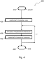
- FIG. 5 A simplified version of an embodiment of a method for measuring fouling or erosion based on sensor arrangement 200 or a similar sensor arrangement, i.e. a simplified version of the embodiment of Fig. 5 , will be explained in the following with reference to a flow chart 400 of Fig. 4 .
- Flow chart 400 comprises a START step 410 and an END step 490.
- the method according to flow chart 400 includes a preliminary step 420 of positioning a first single vibrating mass formed by an assembly of at least a first piezoelectric transducer (for example first piezoelectric transducer 210 in Fig. 2 ) and a first plate (for example first plate 220 in Fig. 2 ), the first plate forming a portion of a flow path wall.
- a first piezoelectric transducer for example first piezoelectric transducer 210 in Fig. 2
- a first plate for example first plate 220 in Fig. 2
- method according to flow chart 400 further includes the steps of:
- the repetition referred to in steps 430 and 440 corresponds to loop L1 in flow chart 400 of Fig. 4 .
- the loop may be repeated with a period preferably longer than 1 hour and preferably shorter than 1 day as fouling and erosion progress quite slowly; it is to be noted that the period of repetition does not need to be strictly constant, for example a variation of up to 10% or 20% (or even more) is acceptable.
- step 420 is carried out when assembling machine 100, while steps 430 and 440 are carried out during operation of machine 100, i.e. they are part of a measuring process.
- Loop L1 may be continuously repeated from start-up of machine 100 to shut-down of machine 100; therefore, advantageously, loop L1 is interrupted when machine 100 is not operating.
- the resonance frequency of the first electric resonance vibration is greater than 20 KHz.
- Steps 430 and 440 may be carried out for example by a measurement or monitor electronic unit of machine 100 that is not shown in any figure and that may be electrically connected to electric cable 214 of sensor arrangement 200.
- the above-mentioned measurement or monitor electronic unit may process the frequency measurements carried out. For example, any time it makes a frequency measurement, it may compare the measured value with an upper threshold value and/or a lower threshold value; if any of these threshold values is exceeded it may signal such event for example to an electronic control unit of the machine and/or to an operator; such signaling may be an electronic indication (for example and electronic message sent to an electronic control unit of the machine) and/or a visual indication and/or a sound indication. It is to be noted that a frequency measurement may be subject to some pre-processing before threshold comparison or comparisons for example in order to take into account the current temperature of the components of the sensor arrangement.
- sensor arrangement 300 is arranged to measure fouling or erosion and comprises at least a first piezoelectric transducer 310 and a first plate 320; first piezoelectric transducer 310 and first plate 320 are fixedly coupled together so to form a first single vibrating mass.
- the sensor arrangement comprises further a first support member 330; first piezoelectric transducer 310 and first plate 320 are fixedly coupled to first support member 330 so that the first single vibrating mass is formed by the combination of first piezoelectric transducer 310, first plate 320 and first support member 330.
- first piezoelectric transducer 310 is fixed to a first side of first support member 330 designed to be remote from a flow path (130 in Fig. 3 ) of a machine and first plate 320 is fixed to a second side of first support member 330 designed to be close to a flow path (130 in Fig. 3 ) of a machine.
- First piezoelectric transducer 310 is arranged to be stimulated by electric signals applied to sensor arrangement 300; for example, Fig. 3 shows an electric cable 314 electrically connected to contacts 312 of first piezoelectric transducer 310, and arranged to feed electric signals to/from first piezoelectric transducer 310.
- Electric cable 314 is arranged to feed stimulation electric signals from e.g. a measurement or monitor electronic unit to first piezoelectric transducer 310.
- Electric cable 314 is also arranged to feed resonance vibration electric signals from first piezoelectric transducer 310 to e.g. a measurement or monitor electronic unit; a resonance vibration electric signal is a consequence of an electric stimulation, typically of a previous electric stimulation.
- sensor arrangement 300 is arranged to be installed in a machine so that first plate 320 is exposed to a working fluid flow F in the machine (i.e. in the flow path of the machine).
- first plate forms a portion of wall 133 of flow path 130; preferably, just after installation of sensor arrangement 300 (i.e. before any fouling and erosion), surface of first plate 320 is aligned with surrounding surface of wall 134.
- Second piezoelectric transducer 340 is arranged to be stimulated by electric signals applied to sensor arrangement 300; for example, Fig. 3 shows an electric cable 344 electrically connected to contacts 342 of second piezoelectric transducer 340, and arranged to feed electric signals to/from second piezoelectric transducer 340.
- Electric cable 344 is arranged to feed stimulation electric signals from e.g. a measurement or monitor electronic unit to first piezoelectric transducer 340.
- Electric cable 344 is also arranged to feed resonance vibration electric signals from second piezoelectric transducer 340 to e.g. a measurement or monitor electronic unit; a resonance vibration electric signal is a consequence of an electric stimulation, typically of a previous electric stimulation.
- sensor arrangement 300 is arranged to be installed in a machine so that second plate 350 is exposed to a working fluid of the machine (i.e. still or at zero flow velocity) but not exposed to a flow F of the working fluid in the machine (i.e. in the flow path of the machine) (that means that should not be subject to fouling or erosion), and so that at least first piezoelectric transducer 310, first plate 320, second piezoelectric transducer 340, and second plate 350 are exposed to a same temperature and to a same pressure. In the embodiment of Fig. 3 , even first support member 330 and second support member 360 are exposed to a same temperature and to a same pressure.
- sensor arrangement 300 may comprise further a first cavity 372.
- the first single vibrating mass i.e. the combination of elements 310+320+330, is positioned on a first side of first cavity 372, while the second single vibrating mass, i.e. the combination of elements 340+350+360, is positioned on a second side of first cavity 372; the second side is different from the first side.
- a hollow separation member 370 is fit between the first single vibrating mass and the second single vibrating mass; a transversal cross-section (not shown in Fig. 3 ) of member 370 may have the shape of a circle or a polygon.
- a separation wall component (not shown in Fig. 3 ) may be located inside first cavity 372; such separation wall component is aimed at avoiding or at least limiting frequency interactions between the first vibrating mass and the second vibrating mass which are unwanted.
- Such separation wall component may take the form for example of disk made of stainless steel and fixed at its boundary to the hollow separation member 370; in this way, first cavity 372 is divided into two sub-cavities.
- sensor arrangement 300 may comprise further a second cavity 382.
- the second single vibrating mass i.e. the combination of elements 340+350+360, is positioned also on a side of second cavity 382.
- first cavity 372 is arranged to be in fluid communication with a working fluid flow path (130 in Fig. 3 ) of the machine; in this way, especially second piezoelectric transducer 340 is exposed approximately to a same temperature and to a same pressure as first piezoelectric transducer 310.
- second cavity 382 is arranged to receive the working fluid of the machine; in this way, especially second plate 350 is exposed approximately to a same temperature and to a same pressure as first plate 320.
- working fluid passes first through a annular duct 384 (read afterwards) and then through a plurality of hole ducts 386 (read afterwards).
- the working fluid slowly diffuses into cavity 382 passing through duct 384 and ducts 386; in the way, the working fluid inside cavity 382 is still and therefore does not erode plate 350; in this way, dirt carried by the working fluid gradually deposits on the walls of duct 384 (that are at an appropriate distance) and when the working fluid enters into cavity 382 it is free (or almost free) from dirt so that it does not foul plate 350.
- sensor arrangement 300 may comprise a tubular shell 380 arranged to be fit in a recess 135 of a wall 134 of a flow path 130 of a machine.
- Tubular shell 380 surrounds both first cavity 372 and second cavity 382.
- Separation member 370 may be fit into an inner annular recess of tubular shell 380 together with a periphery of first support member 330 and a periphery of second support member 360.
- tubular shell 380 has a larger cross-section at its inner zone so to fix inside recess 135 and a small cross-section at its outer zone so to define an annular duct 384 between an inner surface of recess 135 and an outer surface of tubular shell 380. Furthermore in this case, shell 380 has, at its outer zone, a plurality of hole ducts 386 extending from annular duct 384 to second cavity 382.
- a second cavity 382 is arranged to receive the working fluid of the machine, it is preferable to provide a draining channel 388, for example at an inner end of tubular shell 380, arranged to drain liquid from second cavity 382; such liquid may be due to partial condensation of the working fluid.
- a second cavity 382 is arranged to receive the working fluid of the machine, it is preferable to provide a liquid detector 390 positioned in second cavity 382 and arranged to detect for example when liquid in second cavity 382 exceeds a predetermined quantity or level.
- Fig. 3 shows an electric cable 394 electrically connected to liquid detector 390, and arranged to feed electric signals from liquid detector 390 to e.g. a measurement or monitor electronic unit.
- Sensor arrangement 300 as shown in detail in Fig. 3 is used for measuring fouling or erosion on a wall of an internal flow path of machine 100. Although in Fig. 1 , sensor arrangement 300 is mounted to a stator wall, a similar sensor arrangement may alternatively be mounted to a rotor wall.
- the method according to this embodiment is significantly similar to the method previously described.
- the one previously described is based on a sensor arrangement comprising one vibrating mass and this embodiment is based on a sensor arrangement comprising two vibrating masses, i.e. a first vibrating mass and a second vibrating mass.
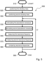
- Flow chart 500 comprises a START step 510 and an END step 590.
- the method according to flow chart 500 includes a preliminary step 520 of positioning a first single vibrating mass formed by an assembly of at least a first piezoelectric transducer (for example first piezoelectric transducer 310 in Fig. 3 ) and a first plate (for example first plate 320 in Fig. 3 ), the first plate forming a portion of a flow path wall.
- a first piezoelectric transducer for example first piezoelectric transducer 310 in Fig. 3
- a first plate for example first plate 320 in Fig. 3
- the method according to flow chart 500 further includes the steps of:
- the method according to flow chart 500 includes a preliminary step 550 of positioning a second single vibrating mass formed by an assembly of at least a second piezoelectric transducer (for example second piezoelectric transducer 340 in Fig. 3 ) and a second plate (for example first plate 350 in Fig. 3 ), the second plate being close to the first plate but remote from a flow path wall.
- a second piezoelectric transducer for example second piezoelectric transducer 340 in Fig. 3
- a second plate for example first plate 350 in Fig. 3
- the method according to flow chart 500 further includes the steps of:
- step 520 As shown in Fig. 5 , the preferable sequence of the above-mentioned steps is: step 520, step 550, step 530, step 560, step 540, step 570 and step 580 (that will be explained below).
- steps 520 and 550 are carried out when assembling machine 100, while steps 530 and 560 and 540 and 570 are carried out during operation of machine 100, i.e. they are part of a measuring process.
- the positioning at step 520 and the positioning at step 550 lead to the first single vibrating mass and the second single vibrating mass being exposed to a same temperature and to a same pressure.
- the repetition referred to in steps 530 and 560 and 540 and 570 and 580 corresponds to loop L2 in flow chart 500 of Fig. 5 .
- the loop may be repeated with a period preferably longer than 1 hour and preferably shorter than 1 day as fouling and erosion progress quite slowly; it is to be noted that the period of repetition does not need to be strictly constant, for example a variation of up to 10% or 20% (or even more) is acceptable.
- Loop L2 may be continuously repeated from start-up of machine 100 to shut-down of machine 100; therefore, advantageously, loop L2 is interrupted when machine 100 is not operating.
- the resonance frequency of the first electric resonance vibration and the resonance frequency of the second electric resonance vibration are greater than 20 KHz even if not always identical.
- the resonance frequency of the first electric resonance vibration and the resonance frequency of the second electric resonance vibration are identical (or almost identical) when the first plate (for example first plate 320 in Fig. 3 ) has no fouling or is not eroded.
- a frequency difference exists and may be measured after fouling or erosion.
- the resonance frequency of the first electric resonance vibration and the resonance frequency of the second electric resonance vibration are different when the first plate (for example first plate 320 in Fig. 3 ) has no fouling or is not eroded; this difference is preferably greater than 500 Hz.
- the frequency difference increases or decreases and may be measured after fouling or erosion.
- Steps 530 and 560 and 540 and 570 may be carried out for example by a measurement or monitor electronic unit of machine 100 that is not shown in any figure and that may be electrically connected to electric cables 314 and 344 of sensor arrangement 300.
- the above-mentioned measurement or monitor electronic unit may process the frequency measurements carried out as well as compare, for example subtract, the measured resonance frequencies (see step 580). For example, any time it makes a frequency subtraction between a resonance frequency of the first electric resonance vibration and a resonance frequency of the second electric resonance vibration, it may compare the subtracted value with an upper threshold value and/or a lower threshold value; if any of these threshold values is exceeded it may signal such event for example to an electronic control unit of the machine and/or to an operator; such signaling may be an electronic indication (for example and electronic message sent to an electronic control unit of the machine) and/or a visual indication and/or a sound indication.
- sensor arrangements identical or similar to sensor arrangement 200 and sensor arrangement 300 may be advantageously installed and used in machines, preferably turbomachines, more preferably single-stage or multi-stage centrifugal compressors.
- Any machine may include one or more such sensor arrangements.
- such a machine may include a measurement or monitor electronic unit or be associated to a measurement or monitor electronic unit; the same unit may be connected (through wired and/or wireless connections) to one or more such sensor arrangements.
- a first plate of the sensor arrangement forms a portion of a wall of a flow path of the machine wherein a working fluid flows. If erosion is measured or monitored, it is advantageous that the first plate is made of a plate material, the wall is made of a wall material, and the plate material and the wall material are a same material; it is even further advantageous that the material of the first plate, the second plate and the wall is the same.
Landscapes
- Physics & Mathematics (AREA)
- Life Sciences & Earth Sciences (AREA)
- Pathology (AREA)
- Health & Medical Sciences (AREA)
- Chemical & Material Sciences (AREA)
- Analytical Chemistry (AREA)
- Biochemistry (AREA)
- General Health & Medical Sciences (AREA)
- General Physics & Mathematics (AREA)
- Immunology (AREA)
- Engineering & Computer Science (AREA)
- Acoustics & Sound (AREA)
- Biodiversity & Conservation Biology (AREA)
- Ecology (AREA)
- Environmental & Geological Engineering (AREA)
- Environmental Sciences (AREA)
- Signal Processing (AREA)
- Mechanical Engineering (AREA)
- General Engineering & Computer Science (AREA)
- Structures Of Non-Positive Displacement Pumps (AREA)
- Investigating Or Analyzing Materials By The Use Of Ultrasonic Waves (AREA)
- Measurement Of Mechanical Vibrations Or Ultrasonic Waves (AREA)
- Testing Of Devices, Machine Parts, Or Other Structures Thereof (AREA)
- Testing Resistance To Weather, Investigating Materials By Mechanical Methods (AREA)
Description
- The subject-matter disclosed herein relates to sensor arrangements and methods for measuring fouling and/or erosion and machines wherein fouling and/or erosion is monitored.
-
EP0785427A1 discloses measuring scaling characteristics of water by means of quartz micro-balance having a plate electrode exposed to a water flow.EP1217359A1 discloses measuring the furring capacity of a liquid by means of a quartz micro-balance having a plate electrode exposed to the liquid.US4808538A discloses measuring the corrosivity of a liquid by means of a piezoelectric crystal coated with a metal which is exposed to the liquid.US6880402B1 discloses a deposition monitoring system comprising two piezoelectric transducers coupled each to a metal horn exposed to a wellbore fluid, wherein one of the horns is cleaned so as to keep it free from deposition.CH683375A5 US2012/264220A1 discloses monitoring corrosion in an air flow by means of quartz micro-balances covered with different metallic coatings which are exposed to the air flow.US2019/094167A1 discloses monitoring corrosion/erosion of a part of a turbomachine exposed to a working fluid, by means of a measurement element exposed to said fluid.US2008/282781A1 discloses monitoring particles in a fluid stream, wherein a corrosion/erosion sensor comprises a sample acoustic sensor and a reference acoustic sensor exposed both to near identical temperature and pressure.US2006/037399A1 discloses a fouling and corrosion detector comprising two piezoelectric elements and associated elements exposed to various fluid flows in an industrial system such as a reactor or boiler.GB2109937A EP0150552A1 discloses an electrical resistance corrosion probe comprising a sample element exposed to the fluid in a vessel or pipeline, and a reference element identical to the sample element and exposed to the same temperature, but insulated from said fluid.US4561286A discloses a contamination detector comprising a chamber housing a piezoelectric measuring resonator and a reference resonator, wherein the reference resonator is protected from external contamination. In general, machines are subject to fouling and/or erosion during their operation. - This is especially true for turbomachines, in particular single-stage or multi-stage centrifugal compressors, wherein fouling and/or erosion during operation are at least partially due to a flowing of working fluid in an internal flow path of the machine. Both fouling and erosion are due to material carried by the flowing working fluid; if flowing velocity is low erosion is also low; if flowing velocity reduces dirt tends to deposit more.
- When fouling (at one or more internal places of the machine) reaches an excessive level, the machine should be stopped, cleaned and restarted; in fact, fouling inside the machine may cause for example loss of efficiency of the machine. Cleaning often requires disassembling the machine which is complicated and time-consuming and thus expensive. Therefore, at least ideally, such maintenance operation should be performed always when necessary but preferably only when necessary.
- When erosion (of one or more components of the machine) reaches an excessive level, the machine should be stopped, repaired and restarted; in fact, if the eroded component should break, huge damages to the machine may occur; in any case, erosion inside the machine may cause for example loss of efficiency of the machine. Repairing always requires disassembling the machine which is complicated and time-consuming and thus expensive. Therefore, at least ideally, such maintenance operation should be performed always when necessary but preferably only when necessary.
- Therefore, it would be desirable to monitor fouling and/or erosion at one or more internal places of the machine so to take the appropriate steps when they reach a predetermined level that is considered excessive.
- The present invention is defined in the accompanying claims. According to one aspect, the subject-matter disclosed herein relates to a system comprising a machine and a sensor arrangement for measuring fouling and/or erosion in the machine. The sensor arrangement includes: a first piezoelectric transducer and a first plate, the first plate being fixedly coupled to the first piezoelectric transducer so to form a first single vibrating mass; the first piezoelectric transducer is arranged to be stimulated by electric signals applied to the sensor arrangement; a second piezoelectric transducer and a second plate, the second plate being fixedly coupled to the second piezoelectric transducer so to form a second single vibrating mass; the second piezoelectric transducer is arranged to be stimulated by electric signals applied to the sensor arrangement; the sensor arrangement is arranged to be installed in the machine so that the first plate is exposed to a flow of a working fluid in the machine (i.e. in the flow path of the machine) while the second plate is exposed to the working fluid but not to its flow (i.e. the fluid is still and the flow velocity is zero).
- There is also disclosed a machine arranged to operate through a working fluid flowing in an internal flow path of the machine; the machine includes at least one sensor arrangement. The sensor arrangement includes: a first piezoelectric transducer and a first plate, the first plate being fixedly coupled to the first piezoelectric transducer so to form a first single vibrating mass; the first piezoelectric transducer is arranged to be stimulated by electric signals applied to the sensor arrangement; a second piezoelectric transducer and a second plate, the second plate being fixedly coupled to the second piezoelectric transducer so to form a second single vibrating mass; the second piezoelectric transducer is arranged to be stimulated by electric signals applied to the sensor arrangement; the sensor arrangement is arranged to be installed in the machine so that the first plate is exposed to a flow of a working fluid in the machine (i.e. in the flow path of the machine) while the second plate is exposed to the working fluid but not to its flow (i.e. the fluid is still and the flow velocity is zero). The first plate forms a portion of a wall of the flow path.
- According to still another aspect, the subject-matter disclosed herein relates to a method as defined in claim 12, for measuring fouling and/or erosion on a wall of an internal flow path of a machine; the method includes the steps of: A) repeatedly stimulating a first piezoelectric transducer by a first stimulation electric signal so that the first piezoelectric transducer generates a first electric resonance vibration, the first piezoelectric transducer being part of a first vibrating mass integrated into said wall; B) repeatedly measuring a resonance frequency of the first electric resonance vibration; C) repeatedly stimulating a second piezoelectric transducer by a second stimulation electric signal so that the second piezoelectric transducer generates a second electric resonance vibration, the second piezoelectric transducer being part of a second vibrating mass positioned close to said first vibrating mass but remote from said wall; D) repeatedly measuring a resonance frequency of said second electric resonance vibration; and E) repeatedly comparing said resonance frequency of said first electric resonance vibration and said resonance frequency of said second electric resonance vibration.
- A more complete appreciation of the disclosed embodiments of the invention and many of the attendant advantages thereof will be readily obtained as the same becomes better understood by reference to the following detailed description when considered in connection with the accompanying drawings, wherein:
- Fig. 1
- illustrates a schematic longitudinal cross-section view of an embodiment of a machine, in particular a multi-stage centrifugal compressor;
- Fig. 2
- illustrates a schematic transversal cross-section view of a simplified version of an embodiment of a sensor arrangement for measuring fouling or erosion, not falling under the scope of the claims;
- Fig. 3
- illustrates a schematic cross-section view of an embodiment of a sensor arrangement for measuring fouling or erosion in a machine;
- Fig. 4
- shows a flow chart of a simplified version of an embodiment of a method of measuring fouling or erosion in a machine, not falling under the scope of the claims; and
- Fig. 5
- shows a flow chart of an embodiment of a method of measuring fouling or erosion in a machine.
- The Applicant has considered that fouling and erosion in a machine imply a mass change inside the machine: in the case of fouling, a mass of material is deposited (i.e. added) in a certain place of the machine (in particular a certain place of a component of the machine); in the case of erosion, a mass of material is removed (i.e. subtracted) from a certain place of the machine (in particular a certain place of a component of the machine).
- Therefore, the Applicant has thought of monitoring fouling and/or erosion by repeating a mass measurement in the one or more places of a machine where one or more of these phenomena are likely to occur. If a mass change is detected, this means that some fouling or erosion has occurred.
- There are various approaches of measuring mass, but it is very difficult to do it inside an operating machine especially in internal places where a working fluid of the machine is flowing.
- The Applicant has identified an approach that is particularly effective in such circumstances, i.e. the inertial balance measurement carried out through a sensor arrangement that will be briefly described in the following.
- A piezoelectric transducer and a plate are fixed together so to form a vibrating mass. After electrically stimulating the piezoelectric transducer, the vibrating mass starts vibrating mechanically, which is called "natural resonance", and consequently the piezoelectric transducer generates an electric resonance vibration; the electric resonance vibration is at a frequency depending on the overall mass of the vibrating mass, which is called "natural resonance frequency". If the overall mass of the vibrating mass changes due to e.g. fouling or erosion in the machine, also the electric vibration frequency changes, i.e. the "natural resonance frequency" changes; such frequency change may be measured and the corresponding mass change may be determined.
- A sensor arrangement operating according to the above described principle may be installed inside a machine (either in a stator component of the machine or in a rotor component of the machine). In case fouling is of interest, the sensor arrangement is positioned so that dirt (due to the working fluid flow) deposits on the plate and changes the overall mass of the vibrating mass. In case erosion is of interest, the sensor arrangement is positioned so that erosion (due to the working fluid flow) acts on the plate and changes the overall mass of the vibrating mass.
- Reference now will be made in detail to various embodiments, one or more examples of which are illustrated in the drawings. Each example is provided by way of explanation of the disclosure, not limitation of the disclosure. In fact, it will be apparent to those skilled in the art that various modifications and variations can be made in the present disclosure without departing from the scope of the claims. Reference throughout the specification to "one embodiment" or "an embodiment" or "some embodiments" means that the particular feature, structure or characteristic described in connection with an embodiment is included in at least one embodiment of the subject matter disclosed. Thus, the appearance of the phrase "in one embodiment" or "in an embodiment" or "in some embodiments" in various places throughout the specification is not necessarily referring to the same embodiment(s). Further, the particular features, structures or characteristics may be combined in any suitable manner in one or more embodiments, insofar as falling under the scope of the claims.
- When introducing elements of various embodiments the articles "a", "an", "the", and "said" are intended to mean that there are one or more of the elements. The terms "comprising", "including", and "having" are intended to be inclusive and mean that there may be additional elements other than the listed elements.
- Referring now to the drawings,
Fig. 1 illustrates a schematic longitudinal cross-section view of an embodiment of amachine 100, in particular a multi-stage centrifugal compressor.Machine 100 comprises arotor 120 and astator 110; in particular,stator 110 surroundsrotor 120. Aninternal flow path 130 is defined betweenstator 110 androtor 120, and develops from an inlet of machine 100 (on the left inFig. 1 ) to an outlet of machine 100 (on the right ofFig. 1 ). During operation ofmachine 100,flow path 130 is arranged to receive a working fluid at the inlet ofmachine 100, feed it and discharge it from the outlet ofmachine 130. In the embodiment ofFig. 1 , by flowing alongflow path 130, in particular inside flow channels of e.g. three impellers ofrotor 120, the working fluid causes rotation ofrotor 120. - Due to the flow of the working fluid in
flow path 130, fouling and/or erosion may occur on one or more parts ofstator 110 and/or ofrotor 120. - In the embodiment of
Fig. 1 , fouling and/or erosion are monitored for example through afirst sensor arrangement 200 and asecond sensor arrangement 300. In general, the number of such sensor arrangements may vary from one to e.g. one hundred. - These sensor arrangements are positioned adjacent to flow path 130 (as will be explained better in the following), specifically a part of a sensor arrangement forms a portion of a wall of the flow path; any of these sensor arrangements may be mounted to
stator 110 orrotor 120.Sensor arrangement 200 is mounted torotor 120 and a part thereof forms a portion ofwall 132.Sensor arrangement 300 is mounted tostator 110 and a part thereof forms a portion ofwall 134. While in the embodiment ofFig. 1 , sensor arrangements are located in an inlet region ofmachine 100, it is to be understood that in alternative embodiments sensor arrangements may be located in the inlet region and/or in the outlet region and/or in an intermediate region of the machine. - If a sensor arrangement, like
e.g. sensor arrangement 300, is mounted to a stator of a machine, a wired connection is used for connecting it for example to a measurement or monitor electronic unit of the machine. - If a sensor arrangement, like
e.g. sensor arrangement 200, is mounted to a rotor of a machine, a wireless connection is used for connecting it for example to a measurement or monitor electronic unit of the machine. As a person skilled in the art understands a wireless connection is more complicated than a wired connection. - Referring now to
Fig. 2 ,sensor arrangement 200 is arranged to measure fouling or erosion and comprises at least a firstpiezoelectric transducer 210 and afirst plate 220; firstpiezoelectric transducer 210 andfirst plate 220 are fixedly coupled together so to form a first single vibrating mass. It is to be noted thatsensor arrangement 200 ofFig. 2 is to be considered a simplified version ofsensor arrangement 300 ofFig. 3 ; the following explanation is useful for understanding the embodiment ofFig. 3 . - In the solution of
Fig. 2 , that is a simplified version of the embodiment ofFig. 3 , the sensor arrangement comprises further afirst support member 230; firstpiezoelectric transducer 210 andfirst plate 220 are fixedly coupled tofirst support member 230 so that the first single vibrating mass is formed by the combination of firstpiezoelectric transducer 210,first plate 220 andfirst support member 230. Advantageously, firstpiezoelectric transducer 210 is fixed to a first side offirst support member 230 designed to be remote from a flow path (130 inFig. 2 ) of a machine andfirst plate 220 is fixed to a second side offirst support member 230 designed to be close to a flow path (130 inFig. 2 ) of a machine. - First
piezoelectric transducer 210 is arranged to be stimulated by electric signals applied tosensor arrangement 200; for example,Fig. 2 shows anelectric cable 214 electrically connected tocontacts 212 of firstpiezoelectric transducer 210, and arranged to feed electric signals to/from firstpiezoelectric transducer 210.Electric cable 214 is arranged to feed stimulation electric signals from e.g. a measurement or monitor electronic unit to firstpiezoelectric transducer 210.Electric cable 214 is also arranged to feed resonance vibration electric signals from firstpiezoelectric transducer 210 to e.g. a measurement or monitor electronic unit; a resonance vibration electric signal is a consequence of an electric stimulation, typically of a previous electric stimulation. - As can been in
Fig. 2 ,sensor arrangement 200 is arranged to be installed in a machine so thatfirst plate 220 is exposed to a flow F of working fluid in the machine (i.e. in the flow path of the machine). Preferably, first plate forms a portion ofwall 132 offlow path 130; preferably, just after installation of sensor arrangement 200 (i.e. before any fouling and/or erosion), surface offirst plate 220 is aligned with surrounding surface ofwall 132. -
Sensor arrangement 200 is positioned inside arecess 133 of awall 132 and is fixed towall 132. According to the solution ofFig. 2 , anannular member 280 is used for fixingsensor arrangement 200 towall 132; for example, a periphery offirst support member 230 is held byannular member 280 andannular member 280 is screwed or fit in a hole ofwall 132. -
Sensor arrangement 200 as shown in detail inFig. 2 is used for measuring fouling or erosion on a wall of an internal flow path ofmachine 100. The solution shown inFig. 2 may be used also for measuring corrosion; however, in this case, is not truly a simplified version of the embodiment ofFig. 3 . Although inFig. 1 ,sensor arrangement 200 is mounted to a rotor wall, a similar sensor arrangement may alternatively be mounted to a stator wall. - A simplified version of an embodiment of a method for measuring fouling or erosion based on
sensor arrangement 200 or a similar sensor arrangement, i.e. a simplified version of the embodiment ofFig. 5 , will be explained in the following with reference to aflow chart 400 ofFig. 4 . -
Flow chart 400 comprises aSTART step 410 and anEND step 490. - The method according to
flow chart 400 includes apreliminary step 420 of positioning a first single vibrating mass formed by an assembly of at least a first piezoelectric transducer (for example firstpiezoelectric transducer 210 inFig. 2 ) and a first plate (for examplefirst plate 220 inFig. 2 ), the first plate forming a portion of a flow path wall. - Furthermore, the method according to
flow chart 400 further includes the steps of: - A) step 430: repeatedly stimulating the first piezoelectric transducer (for example first
piezoelectric transducer 210 inFig. 2 ) by a first stimulation electric signal so that the first piezoelectric transducer (for example firstpiezoelectric transducer 210 inFig. 2 ) generates a first electric resonance vibration, and - B) step 440: repeatedly measuring a resonance frequency of said first electric resonance vibration (that may be called "first resonance frequency").
- The repetition referred to in
steps flow chart 400 ofFig. 4 . The loop may be repeated with a period preferably longer than 1 hour and preferably shorter than 1 day as fouling and erosion progress quite slowly; it is to be noted that the period of repetition does not need to be strictly constant, for example a variation of up to 10% or 20% (or even more) is acceptable. - It is to be noted that
step 420 is carried out when assemblingmachine 100, whilesteps machine 100, i.e. they are part of a measuring process. Loop L1 may be continuously repeated from start-up ofmachine 100 to shut-down ofmachine 100; therefore, advantageously, loop L1 is interrupted whenmachine 100 is not operating. - Preferably, the resonance frequency of the first electric resonance vibration is greater than 20 KHz.
-
Steps machine 100 that is not shown in any figure and that may be electrically connected toelectric cable 214 ofsensor arrangement 200. - The above-mentioned measurement or monitor electronic unit may process the frequency measurements carried out. For example, any time it makes a frequency measurement, it may compare the measured value with an upper threshold value and/or a lower threshold value; if any of these threshold values is exceeded it may signal such event for example to an electronic control unit of the machine and/or to an operator; such signaling may be an electronic indication (for example and electronic message sent to an electronic control unit of the machine) and/or a visual indication and/or a sound indication. It is to be noted that a frequency measurement may be subject to some pre-processing before threshold comparison or comparisons for example in order to take into account the current temperature of the components of the sensor arrangement.
- Referring now to
Fig. 3 ,sensor arrangement 300 is arranged to measure fouling or erosion and comprises at least a firstpiezoelectric transducer 310 and afirst plate 320; firstpiezoelectric transducer 310 andfirst plate 320 are fixedly coupled together so to form a first single vibrating mass. - In the embodiment of
Fig. 3 , the sensor arrangement comprises further afirst support member 330; firstpiezoelectric transducer 310 andfirst plate 320 are fixedly coupled tofirst support member 330 so that the first single vibrating mass is formed by the combination of firstpiezoelectric transducer 310,first plate 320 andfirst support member 330. Advantageously, firstpiezoelectric transducer 310 is fixed to a first side offirst support member 330 designed to be remote from a flow path (130 inFig. 3 ) of a machine andfirst plate 320 is fixed to a second side offirst support member 330 designed to be close to a flow path (130 inFig. 3 ) of a machine. - First
piezoelectric transducer 310 is arranged to be stimulated by electric signals applied tosensor arrangement 300; for example,Fig. 3 shows anelectric cable 314 electrically connected tocontacts 312 of firstpiezoelectric transducer 310, and arranged to feed electric signals to/from firstpiezoelectric transducer 310.Electric cable 314 is arranged to feed stimulation electric signals from e.g. a measurement or monitor electronic unit to firstpiezoelectric transducer 310.Electric cable 314 is also arranged to feed resonance vibration electric signals from firstpiezoelectric transducer 310 to e.g. a measurement or monitor electronic unit; a resonance vibration electric signal is a consequence of an electric stimulation, typically of a previous electric stimulation. - As can been in
Fig. 3 ,sensor arrangement 300 is arranged to be installed in a machine so thatfirst plate 320 is exposed to a working fluid flow F in the machine (i.e. in the flow path of the machine). Preferably, first plate forms a portion ofwall 133 offlow path 130; preferably, just after installation of sensor arrangement 300 (i.e. before any fouling and erosion), surface offirst plate 320 is aligned with surrounding surface ofwall 134. -
Sensor arrangement 300 comprises further at least a secondpiezoelectric transducer 340 and asecond plate 350; secondpiezoelectric transducer 340 andsecond plate 350 are fixedly coupled together so to form a second single vibrating mass. - In the embodiment of
Fig. 3 , the sensor arrangement comprises further asecond support member 360; secondpiezoelectric transducer 340 andsecond plate 350 are fixedly coupled tosecond support member 360 so that the second single vibrating mass is formed by the combination of secondpiezoelectric transducer 340,second plate 350 andsecond support member 360. Advantageously, secondpiezoelectric transducer 340 is fixed to a first side ofsecond support member 360 designed to be close to a flow path (130 inFig. 3 ) of a machine andsecond plate 350 is fixed to a second side ofsecond support member 360 designed to be remote from a flow path (130 inFig. 3 ) of a machine. - Second
piezoelectric transducer 340 is arranged to be stimulated by electric signals applied tosensor arrangement 300; for example,Fig. 3 shows anelectric cable 344 electrically connected tocontacts 342 of secondpiezoelectric transducer 340, and arranged to feed electric signals to/from secondpiezoelectric transducer 340.Electric cable 344 is arranged to feed stimulation electric signals from e.g. a measurement or monitor electronic unit to firstpiezoelectric transducer 340.Electric cable 344 is also arranged to feed resonance vibration electric signals from secondpiezoelectric transducer 340 to e.g. a measurement or monitor electronic unit; a resonance vibration electric signal is a consequence of an electric stimulation, typically of a previous electric stimulation. - As can been in
Fig. 3 ,sensor arrangement 300 is arranged to be installed in a machine so thatsecond plate 350 is exposed to a working fluid of the machine (i.e. still or at zero flow velocity) but not exposed to a flow F of the working fluid in the machine (i.e. in the flow path of the machine) (that means that should not be subject to fouling or erosion), and so that at least firstpiezoelectric transducer 310,first plate 320, secondpiezoelectric transducer 340, andsecond plate 350 are exposed to a same temperature and to a same pressure. In the embodiment ofFig. 3 , evenfirst support member 330 andsecond support member 360 are exposed to a same temperature and to a same pressure. - According to the embodiment of
Fig. 3 ,sensor arrangement 300 may comprise further afirst cavity 372. The first single vibrating mass, i.e. the combination ofelements 310+320+330, is positioned on a first side offirst cavity 372, while the second single vibrating mass, i.e. the combination ofelements 340+350+360, is positioned on a second side offirst cavity 372; the second side is different from the first side. - Preferably and as shown in
Fig. 3 , the second side is opposite to the first side. Advantageously, ahollow separation member 370 is fit between the first single vibrating mass and the second single vibrating mass; a transversal cross-section (not shown inFig. 3 ) ofmember 370 may have the shape of a circle or a polygon. - Advantageously, a separation wall component (not shown in
Fig. 3 ) may be located insidefirst cavity 372; such separation wall component is aimed at avoiding or at least limiting frequency interactions between the first vibrating mass and the second vibrating mass which are unwanted. Such separation wall component may take the form for example of disk made of stainless steel and fixed at its boundary to thehollow separation member 370; in this way,first cavity 372 is divided into two sub-cavities. - According to the embodiment of
Fig. 3 ,sensor arrangement 300 may comprise further asecond cavity 382. The second single vibrating mass, i.e. the combination ofelements 340+350+360, is positioned also on a side ofsecond cavity 382. - Advantageously,
first cavity 372 is arranged to be in fluid communication with a working fluid flow path (130 inFig. 3 ) of the machine; in this way, especially secondpiezoelectric transducer 340 is exposed approximately to a same temperature and to a same pressure as firstpiezoelectric transducer 310. - Advantageously,
second cavity 382 is arranged to receive the working fluid of the machine; in this way, especiallysecond plate 350 is exposed approximately to a same temperature and to a same pressure asfirst plate 320. In the embodiment ofFig. 3 , working fluid passes first through a annular duct 384 (read afterwards) and then through a plurality of hole ducts 386 (read afterwards). It is to noted that the working fluid slowly diffuses intocavity 382 passing throughduct 384 andducts 386; in the way, the working fluid insidecavity 382 is still and therefore does not erodeplate 350; in this way, dirt carried by the working fluid gradually deposits on the walls of duct 384 (that are at an appropriate distance) and when the working fluid enters intocavity 382 it is free (or almost free) from dirt so that it does notfoul plate 350. - From the mechanical point of view,
sensor arrangement 300 may comprise atubular shell 380 arranged to be fit in arecess 135 of awall 134 of aflow path 130 of a machine.Tubular shell 380 surrounds bothfirst cavity 372 andsecond cavity 382.Separation member 370 may be fit into an inner annular recess oftubular shell 380 together with a periphery offirst support member 330 and a periphery ofsecond support member 360. - Advantageously,
tubular shell 380 has a larger cross-section at its inner zone so to fix insiderecess 135 and a small cross-section at its outer zone so to define anannular duct 384 between an inner surface ofrecess 135 and an outer surface oftubular shell 380. Furthermore in this case,shell 380 has, at its outer zone, a plurality ofhole ducts 386 extending fromannular duct 384 tosecond cavity 382. - As, according to this embodiment, a
second cavity 382 is arranged to receive the working fluid of the machine, it is preferable to provide a drainingchannel 388, for example at an inner end oftubular shell 380, arranged to drain liquid fromsecond cavity 382; such liquid may be due to partial condensation of the working fluid. - As, according to this embodiment, a
second cavity 382 is arranged to receive the working fluid of the machine, it is preferable to provide aliquid detector 390 positioned insecond cavity 382 and arranged to detect for example when liquid insecond cavity 382 exceeds a predetermined quantity or level.Fig. 3 shows anelectric cable 394 electrically connected toliquid detector 390, and arranged to feed electric signals fromliquid detector 390 to e.g. a measurement or monitor electronic unit. -
Sensor arrangement 300 as shown in detail inFig. 3 is used for measuring fouling or erosion on a wall of an internal flow path ofmachine 100. Although inFig. 1 ,sensor arrangement 300 is mounted to a stator wall, a similar sensor arrangement may alternatively be mounted to a rotor wall. - An embodiment of a method for measuring fouling or erosion based on
sensor arrangement 300 or a similar sensor arrangement will be explained in the following with reference to aflow chart 500 ofFig. 5 . - The method according to this embodiment is significantly similar to the method previously described. In fact, the one previously described is based on a sensor arrangement comprising one vibrating mass and this embodiment is based on a sensor arrangement comprising two vibrating masses, i.e. a first vibrating mass and a second vibrating mass.
-
Flow chart 500 comprises aSTART step 510 and anEND step 590. - As far as the first vibrating mass is concerned, the method according to
flow chart 500 includes apreliminary step 520 of positioning a first single vibrating mass formed by an assembly of at least a first piezoelectric transducer (for example firstpiezoelectric transducer 310 inFig. 3 ) and a first plate (for examplefirst plate 320 inFig. 3 ), the first plate forming a portion of a flow path wall. - Still as far as the first vibrating mass is concerned, the method according to
flow chart 500 further includes the steps of: - A) step 530: repeatedly stimulating the first piezoelectric transducer (for example first
piezoelectric transducer 310 inFig. 3 ) by a first stimulation electric signal so that the first piezoelectric transducer (for example firstpiezoelectric transducer 310 inFig. 3 ) generates a first electric resonance vibration, and - B) step 540: repeatedly measuring a resonance frequency of said first electric resonance vibration (that may be called "first resonance frequency").
- As far as the second vibrating mass is concerned, the method according to
flow chart 500 includes apreliminary step 550 of positioning a second single vibrating mass formed by an assembly of at least a second piezoelectric transducer (for example secondpiezoelectric transducer 340 inFig. 3 ) and a second plate (for examplefirst plate 350 inFig. 3 ), the second plate being close to the first plate but remote from a flow path wall. In particular, while the first plate is exposed to a flow of a working fluid in the machine (i.e. in the flow path of the machine), the second plate is exposed to the working fluid but not to its flow (i.e. the fluid is still and the flow velocity is zero). - Still as far as the second vibrating mass is concerned, the method according to
flow chart 500 further includes the steps of: - C) step 560: repeatedly stimulating the second piezoelectric transducer (for example second
piezoelectric transducer 340 inFig. 3 ) by a second stimulation electric signal so that the second piezoelectric transducer (for example secondpiezoelectric transducer 340 inFig. 3 ) generates a second electric resonance vibration, and - D) step 570: repeatedly measuring a resonance frequency of said second electric resonance vibration (that may be called "second resonance frequency").
- As shown in
Fig. 5 , the preferable sequence of the above-mentioned steps is:step 520,step 550,step 530,step 560,step 540,step 570 and step 580 (that will be explained below). - It is to be noted that
steps machine 100, whilesteps machine 100, i.e. they are part of a measuring process. - Preferably, the positioning at
step 520 and the positioning atstep 550 lead to the first single vibrating mass and the second single vibrating mass being exposed to a same temperature and to a same pressure. - Advantageously, the method according to
flow chart 500 further includes the step of:
E) step 580: repeatedly comparing the resonance frequencies, in particular the resonance frequency of the first electric resonance vibration and the resonance frequency of the second electric resonance vibration. - The repetition referred to in
steps flow chart 500 ofFig. 5 . The loop may be repeated with a period preferably longer than 1 hour and preferably shorter than 1 day as fouling and erosion progress quite slowly; it is to be noted that the period of repetition does not need to be strictly constant, for example a variation of up to 10% or 20% (or even more) is acceptable. - Loop L2 may be continuously repeated from start-up of
machine 100 to shut-down ofmachine 100; therefore, advantageously, loop L2 is interrupted whenmachine 100 is not operating. - Preferably, the resonance frequency of the first electric resonance vibration and the resonance frequency of the second electric resonance vibration are greater than 20 KHz even if not always identical.
- According to a first possibility, the resonance frequency of the first electric resonance vibration and the resonance frequency of the second electric resonance vibration are identical (or almost identical) when the first plate (for example
first plate 320 inFig. 3 ) has no fouling or is not eroded. A frequency difference exists and may be measured after fouling or erosion. - According to a second preferable possibility, the resonance frequency of the first electric resonance vibration and the resonance frequency of the second electric resonance vibration are different when the first plate (for example
first plate 320 inFig. 3 ) has no fouling or is not eroded; this difference is preferably greater than 500 Hz. The frequency difference increases or decreases and may be measured after fouling or erosion. -
Steps machine 100 that is not shown in any figure and that may be electrically connected toelectric cables sensor arrangement 300. - The above-mentioned measurement or monitor electronic unit may process the frequency measurements carried out as well as compare, for example subtract, the measured resonance frequencies (see step 580). For example, any time it makes a frequency subtraction between a resonance frequency of the first electric resonance vibration and a resonance frequency of the second electric resonance vibration, it may compare the subtracted value with an upper threshold value and/or a lower threshold value; if any of these threshold values is exceeded it may signal such event for example to an electronic control unit of the machine and/or to an operator; such signaling may be an electronic indication (for example and electronic message sent to an electronic control unit of the machine) and/or a visual indication and/or a sound indication.
- It is to be noted that, advantageously, the use of two vibrating masses (at the same temperature and pressure) allows an automatic compensation of the frequency measurements; therefore, some pre-processing before threshold comparison or comparisons may be unnecessary.
- As already explained, sensor arrangements identical or similar to
sensor arrangement 200 andsensor arrangement 300 may be advantageously installed and used in machines, preferably turbomachines, more preferably single-stage or multi-stage centrifugal compressors. - Any machine may include one or more such sensor arrangements.
- Furthermore, such a machine may include a measurement or monitor electronic unit or be associated to a measurement or monitor electronic unit; the same unit may be connected (through wired and/or wireless connections) to one or more such sensor arrangements.
- In these cases, preferably, a first plate of the sensor arrangement forms a portion of a wall of a flow path of the machine wherein a working fluid flows. If erosion is measured or monitored, it is advantageous that the first plate is made of a plate material, the wall is made of a wall material, and the plate material and the wall material are a same material; it is even further advantageous that the material of the first plate, the second plate and the wall is the same.
Claims (15)
- A system comprising a sensor arrangement (200, 300) for measuring fouling and/or erosion in a machine (100) and a machine (100) in which the sensor arrangement is installed, the system comprising:- a first piezoelectric transducer (210, 310),- a first plate (220, 320), the first plate (220, 320) being fixedly coupled to the first piezoelectric transducer (210, 310) so to form a first single vibrating mass (210+220+230, 310+320+330),- a second piezoelectric transducer (340), and- a second plate (350), the second plate (350) being fixedly coupled to the second piezoelectric transducer (340) so to form a second single vibrating mass (340+350+360);wherein the first piezoelectric transducer (210, 310) is arranged to be stimulated by electric signals applied (214, 314) to the sensor arrangement (200, 300);wherein the sensor arrangement (200, 300) is installed in the machine (100) so that the first plate (220, 320) is exposed to a flow (F) of a working fluid in the machine (100);wherein the second piezoelectric transducer (340) is arranged to be stimulated by electric signals applied (344) to the sensor arrangement (300);wherein the sensor arrangement (300) is installed in the machine (100) so that the second plate (350) is exposed to the working fluid of the machine (100) and not exposed to a flow (F) of said working fluid in the machine (100);wherein the second single vibrating mass (340+350+360) is equal to the first single vibrating mass (310+320+330); andwherein the sensor arrangement (300) is installed in the machine (100) that the first piezoelectric transducer (310), the first plate (320), the second piezoelectric transducer (340), the second plate (350) are exposed to a same temperature and to a same pressure.
- The system of claim 1, further comprising:- a first cavity (372);wherein the first single vibrating mass (310+320+330) is positioned on a first side of the first cavity (372);wherein the second single vibrating mass (340+350+360) is positioned on a second side of the first cavity (372); andwherein the second side is different from the first side.
- The system of claim 2,wherein the second side is opposite to the first side; andwherein a hollow member (370) is fit between the first single vibrating mass (310+320+330) and the second single vibrating mass (340+350+360).
- The system of claim 2 or 3, further comprising:- a second cavity (382);wherein the second single vibrating mass (340+350+360) is positioned also on a side of the second cavity (382); andwherein the second cavity (382) receives (384+386) the working fluid of the machine (100).
- The system of claim 4,
wherein the first cavity (372) is in fluid communication with a working fluid flow path of the machine (100). - The system of claim 4 or 5, further comprising:- a draining channel (388);wherein the draining channel (388) is fluidly coupled to the second cavity (382) and is arranged to drain liquid from the second cavity (382).
- The system of claim 4 or 5 or 6, further comprising:- a liquid detector (390);wherein the liquid detector (390) is positioned in the second cavity (382).
- The system of any of claims 4 to 7, further comprising:- a tubular shell (380) surrounding both the first cavity (372) and the second cavity (382) and arranged to be fit in a recess (135) of a wall (134) of a flow path (130) of the machine (100).
- The system of any one of the preceding claims, wherein the machine (100) is arranged to operate through a working fluid flowing in an internal flow path (130) of the machine,
wherein the first plate (220, 320) forms a portion of a wall (132, 134) of said flow path (130). - The system of claim 9,wherein said first plate (220, 320) is made of a plate material;wherein said wall (132) is made of a wall material; andwherein the plate material and the wall material are a same material.
- The system of claim 9 or 10, the machine (100) being a turbomachine, preferably a single-stage or multi-stage centrifugal compressor.
- A method (400, 500) for measuring fouling and/or erosion on a wall of an internal flow path of a machine, the method comprising the steps of:A) repeatedly stimulating (430, 530) a first piezoelectric transducer (310) by a first stimulation electric signal so that the first piezoelectric transducer generates a first electric resonance vibration, a first plate (320) being fixedly coupled to the first piezoelectric transducer to form a first vibrating mass integrated into said wall and exposed to a flow (F) of a working fluid in the machine;B) repeatedly measuring (440, 540) a resonance frequency of said first electric resonance vibration;C) repeatedly stimulating (560) a second piezoelectric transducer (340) by a second stimulation electric signal so that the second piezoelectric transducer generates a second electric resonance vibration, a second plate (350) being fixedly coupled to the second piezoelectric transducer to form a second vibrating mass exposed to the working fluid of the machine and not exposed to a flow (F) of said working fluid in the machine, the first piezoelectric transducer (310), the first plate (320), the second piezoelectric transducer (340) and the second plate (350) being exposed to a same temperature and to a same pressure;D) repeatedly measuring (570) a resonance frequency of said second electric resonance vibration; andE) repeatedly comparing (580) said resonance frequency of said first electric resonance vibration and said resonance frequency of said second electric resonance vibration.
- The method (400, 500) of claim 12,
wherein said resonance frequency of said first electric resonance vibration is greater than 20 KHz. - The method (500) of claim 12 or 13,
wherein said resonance frequency of said second electric resonance vibration is greater than 20 KHz. - The method (500) of claim 12 or 13 or 14,
wherein said resonance frequency of said first electric resonance vibration and said resonance frequency of said second electric resonance vibration are different, a difference between said resonance frequency of said first electric resonance vibration and said resonance frequency of said second electric resonance vibration being greater than 500 Hz when the first plate (320) has no fouling and is not eroded.
Applications Claiming Priority (2)
| Application Number | Priority Date | Filing Date | Title |
|---|---|---|---|
| IT102019000006274A IT201900006274A1 (en) | 2019-04-23 | 2019-04-23 | Arrangement with sensor and method for measuring fouling or erosion or corrosion as well as machine monitoring fouling or erosion or corrosion |
| PCT/EP2020/025179 WO2020216469A1 (en) | 2019-04-23 | 2020-04-20 | Sensor arrangement and method for measuring fouling and/or erosion, and machine monitoring fouling and/or erosion |
Publications (2)
| Publication Number | Publication Date |
|---|---|
| EP3959516A1 EP3959516A1 (en) | 2022-03-02 |
| EP3959516B1 true EP3959516B1 (en) | 2025-03-05 |
Family
ID=67262964
Family Applications (1)
| Application Number | Title | Priority Date | Filing Date |
|---|---|---|---|
| EP20721416.4A Active EP3959516B1 (en) | 2019-04-23 | 2020-04-20 | Sensor arrangement and method for measuring fouling and/or erosion |
Country Status (10)
| Country | Link |
|---|---|
| US (1) | US12235242B2 (en) |
| EP (1) | EP3959516B1 (en) |
| JP (1) | JP7278412B2 (en) |
| KR (1) | KR102546456B1 (en) |
| CN (1) | CN113785194B (en) |
| AU (1) | AU2020261165B2 (en) |
| CA (1) | CA3136839C (en) |
| ES (1) | ES3025632T3 (en) |
| IT (1) | IT201900006274A1 (en) |
| WO (1) | WO2020216469A1 (en) |
Families Citing this family (2)
| Publication number | Priority date | Publication date | Assignee | Title |
|---|---|---|---|---|
| GB202115178D0 (en) * | 2021-10-22 | 2021-12-08 | Rolls Royce Plc | Gas passage |
| JP2024049715A (en) * | 2022-09-29 | 2024-04-10 | 三菱重工コンプレッサ株式会社 | Compressor System |
Family Cites Families (29)
| Publication number | Priority date | Publication date | Assignee | Title |
|---|---|---|---|---|
| GB2109937B (en) * | 1981-11-09 | 1986-02-12 | Joshua Creer Quayle | Planar transducer for metal loss measurement |
| CH662421A5 (en) | 1983-07-13 | 1987-09-30 | Suisse Horlogerie Rech Lab | PIEZOELECTRIC CONTAMINATION DETECTOR. |
| SE8401581L (en) * | 1984-03-21 | 1985-09-22 | Foersvarets Forskningsanstalt | METHOD AND APPARATUS FOR SATURING CORROSIVITY OR REACTIVITY FOR FOREST METALS |
| EP0150552B2 (en) * | 1984-05-17 | 1992-12-23 | SSL Limited | Electrical resistance corrosion probe |
| GB2251308B (en) * | 1990-12-22 | 1994-09-07 | Schlumberger Ind Ltd | Sensors |
| CH683375A5 (en) * | 1991-10-01 | 1994-02-28 | Vibro Meter Ag | Detecting presence, level or condition of fluid - using evaluation circuit to register frequency of diaphragm inserted flush into wall of vessel |
| FR2743634B1 (en) * | 1996-01-17 | 1998-03-06 | Inst Francais Du Petrole | METHOD AND DEVICE FOR CONTINUOUSLY MONITORING THE POWER OF CALCULATION OF WATER |
| US6196059B1 (en) * | 1997-08-11 | 2001-03-06 | Fraunhofer Gesellschaft Zur Forderung Der Angewandten Forschung E.V. | Piezoelectric resonator, process for the fabrication thereof including its use as a sensor element for the determination of the concentration of a substance contained in a liquid and/or for the determination of the physical properties of the liquid |
| GB9925373D0 (en) * | 1999-10-27 | 1999-12-29 | Schlumberger Ltd | Downhole instrumentation and cleaning system |
| FR2818380B1 (en) * | 2000-12-20 | 2003-04-04 | Total Raffinage Distribution | METHOD FOR MEASURING THE BEARING POWER OF A QUARTZ MICROBALANCE AND LIQUID FOR CARRYING OUT THIS METHOD |
| US7866211B2 (en) * | 2004-07-16 | 2011-01-11 | Rosemount Inc. | Fouling and corrosion detector for process control industries |
| JP4616123B2 (en) * | 2005-08-23 | 2011-01-19 | セイコーインスツル株式会社 | Microsensor for analysis |
| GB0522312D0 (en) * | 2005-11-01 | 2005-12-07 | Cormon Ltd | Monitoring particles in a fluid stream |
| US7723989B2 (en) * | 2007-08-31 | 2010-05-25 | Schlumberger Technology Corporation | Transducer assemblies for subsurface use |
| CN101241125B (en) * | 2008-03-10 | 2013-02-13 | 施晓燕 | Piezoelectric sensor for liquid phase measuring and encapsulation method |
| CN102080972A (en) * | 2009-11-30 | 2011-06-01 | 西门子公司 | External cavity-type optical fiber Fabry-Perot sensor and system and method for vibration monitoring |
| JP5888330B2 (en) * | 2010-09-07 | 2016-03-22 | レオニクス ゲーエムベーハー | Fluid characteristic measuring apparatus having a symmetrical resonator |
| CN102012251B (en) * | 2010-09-29 | 2012-08-15 | 西安东风机电有限公司 | Method and device for detecting additives, abrasion or corrosion on wall of vibrating tube of Coriolis mass flowmeter |
| EP2458377B1 (en) * | 2010-11-29 | 2019-07-31 | Air Products And Chemicals, Inc. | Method of, and apparatus for, measuring the molecular weight of a gas |
| US20120264220A1 (en) * | 2011-04-14 | 2012-10-18 | Rahmathullah M Aflal | Apparatus for Monitoring Corrosion and Method Thereof |
| WO2012177737A1 (en) * | 2011-06-21 | 2012-12-27 | Ohio University | Device and method for monitoring interaction between a fluid and a wall |
| DE102011089808A1 (en) * | 2011-12-23 | 2013-06-27 | Endress + Hauser Flowtec Ag | Method or measuring system for determining a density of a fluid |
| CN103398686B (en) * | 2013-08-20 | 2015-12-23 | 厦门大学 | A kind of aperture aspherical optical elements Precision measurement platform Z axis counter weight device |
| GB2547284B (en) * | 2016-02-15 | 2019-11-06 | Ft Tech Uk Ltd | Acoustic resonator sensor for determining temperature |
| CN107688100B (en) * | 2017-09-22 | 2019-04-05 | 上海交通大学 | A kind of pipeline stream flow monitoring self-powered sensor based on vortex-induced vibration |
| IT201700108888A1 (en) * | 2017-09-28 | 2019-03-28 | Nuovo Pignone Tecnologie Srl | METHOD OF PROVIDING MONITORING OF EROSION AND / OR CORROSION IN A MACHINE AND MACHINE / METHOD TO ALLOW TO MONITOR EROSION AND / OR CORROSION IN A MACHINE AND MACHINE |
| CN108896745B (en) * | 2018-06-14 | 2020-11-10 | 上海建工集团股份有限公司 | Concrete pumping ultrasonic guided wave monitoring device and monitoring method |
| CN109374729B (en) * | 2018-09-25 | 2021-02-19 | 深圳大学 | Acoustic micro-mass sensor and detection method |
| CN109164004B (en) * | 2018-10-02 | 2023-12-19 | 吉林大学 | Porous particle specific surface area characterization sensor and method based on BET gravimetric method |
-
2019
- 2019-04-23 IT IT102019000006274A patent/IT201900006274A1/en unknown
-
2020
- 2020-04-20 WO PCT/EP2020/025179 patent/WO2020216469A1/en not_active Ceased
- 2020-04-20 ES ES20721416T patent/ES3025632T3/en active Active
- 2020-04-20 CN CN202080032921.XA patent/CN113785194B/en active Active
- 2020-04-20 JP JP2021560132A patent/JP7278412B2/en active Active
- 2020-04-20 KR KR1020217037392A patent/KR102546456B1/en active Active
- 2020-04-20 CA CA3136839A patent/CA3136839C/en active Active
- 2020-04-20 EP EP20721416.4A patent/EP3959516B1/en active Active
- 2020-04-20 AU AU2020261165A patent/AU2020261165B2/en active Active
- 2020-04-20 US US17/594,515 patent/US12235242B2/en active Active
Also Published As
| Publication number | Publication date |
|---|---|
| US12235242B2 (en) | 2025-02-25 |
| AU2020261165B2 (en) | 2023-05-25 |
| JP7278412B2 (en) | 2023-05-19 |
| CA3136839C (en) | 2024-01-30 |
| US20220196606A1 (en) | 2022-06-23 |
| KR102546456B1 (en) | 2023-06-22 |
| EP3959516A1 (en) | 2022-03-02 |
| WO2020216469A1 (en) | 2020-10-29 |
| IT201900006274A1 (en) | 2020-10-23 |
| ES3025632T3 (en) | 2025-06-09 |
| CN113785194A (en) | 2021-12-10 |
| AU2020261165A1 (en) | 2021-11-18 |
| CN113785194B (en) | 2023-11-17 |
| CA3136839A1 (en) | 2020-10-29 |
| KR20210154824A (en) | 2021-12-21 |
| JP2022530326A (en) | 2022-06-29 |
Similar Documents
| Publication | Publication Date | Title |
|---|---|---|
| CN101988889B (en) | For the system and method for on-line monitoring corrosion of gas turbine components | |
| US5681986A (en) | Acoustic sensing | |
| TW558789B (en) | Semiconductor processing device and diagnostic method of semiconductor processing device | |
| EP1734354A2 (en) | Engine status detection with external microphone | |
| US12235242B2 (en) | Sensor arrangement and method for measuring fouling and/or erosion, and machine monitoring fouling and/or erosion | |
| EP3462033B1 (en) | Method of providing monitoring of erosion and/or corrosion in a machine and machine | |
| JP6151370B2 (en) | Condensate drain pipe monitoring | |
| US9228867B2 (en) | Apparatus for characterising a flow through a conduit | |
| KR102648925B1 (en) | Systems and methods for predicting and controlling gas line performance | |
| Alfayez et al. | Detection of incipient cavitation and determination of the best efficiency point for centrifugal pumps using acoustic emission | |
| JP3718377B2 (en) | Corrosion environment damage diagnosis method and apparatus for machine structural parts | |
| Rhakasywi et al. | Safety factor of pump vibrations on ships based on the natural frequency of pump vibrations according to ISO 10816-3 | |
| EP1547023B1 (en) | Method and device for determination of the condition of a turbine blade, and utilizing the collected information for estimation of the lifetime of the blade | |
| CN110296099B (en) | Pump unit and method for monitoring liquid portion in seal structure in pump unit | |
| Higham et al. | Predictive maintenance of pumps based on signal analysis of pressure and differential pressure (flow) measurements | |
| JP2002181525A (en) | Device for measuring interval of impeller for pump and anomaly determining method | |
| EP2751544B1 (en) | Apparatus for characterising a flow through a conduit | |
| CN100473958C (en) | Monitoring and diagnosing a technical installation using purely mechanically activated signaling means |
Legal Events
| Date | Code | Title | Description |
|---|---|---|---|
| STAA | Information on the status of an ep patent application or granted ep patent |
Free format text: STATUS: UNKNOWN |
|
| STAA | Information on the status of an ep patent application or granted ep patent |
Free format text: STATUS: THE INTERNATIONAL PUBLICATION HAS BEEN MADE |
|
| PUAI | Public reference made under article 153(3) epc to a published international application that has entered the european phase |
Free format text: ORIGINAL CODE: 0009012 |
|
| STAA | Information on the status of an ep patent application or granted ep patent |
Free format text: STATUS: REQUEST FOR EXAMINATION WAS MADE |
|
| 17P | Request for examination filed |
Effective date: 20211110 |
|
| AK | Designated contracting states |
Kind code of ref document: A1 Designated state(s): AL AT BE BG CH CY CZ DE DK EE ES FI FR GB GR HR HU IE IS IT LI LT LU LV MC MK MT NL NO PL PT RO RS SE SI SK SM TR |
|
| DAV | Request for validation of the european patent (deleted) | ||
| DAX | Request for extension of the european patent (deleted) | ||
| P01 | Opt-out of the competence of the unified patent court (upc) registered |
Effective date: 20230526 |
|
| STAA | Information on the status of an ep patent application or granted ep patent |
Free format text: STATUS: EXAMINATION IS IN PROGRESS |
|
| 17Q | First examination report despatched |
Effective date: 20231019 |
|
| GRAP | Despatch of communication of intention to grant a patent |
Free format text: ORIGINAL CODE: EPIDOSNIGR1 |
|
| STAA | Information on the status of an ep patent application or granted ep patent |
Free format text: STATUS: GRANT OF PATENT IS INTENDED |
|
| INTG | Intention to grant announced |
Effective date: 20241203 |
|
| GRAS | Grant fee paid |
Free format text: ORIGINAL CODE: EPIDOSNIGR3 |
|
| GRAA | (expected) grant |
Free format text: ORIGINAL CODE: 0009210 |
|
| STAA | Information on the status of an ep patent application or granted ep patent |
Free format text: STATUS: THE PATENT HAS BEEN GRANTED |
|
| AK | Designated contracting states |
Kind code of ref document: B1 Designated state(s): AL AT BE BG CH CY CZ DE DK EE ES FI FR GB GR HR HU IE IS IT LI LT LU LV MC MK MT NL NO PL PT RO RS SE SI SK SM TR |
|
| REG | Reference to a national code |
Ref country code: GB Ref legal event code: FG4D |
|
| REG | Reference to a national code |
Ref country code: CH Ref legal event code: EP |
|
| REG | Reference to a national code |
Ref country code: DE Ref legal event code: R096 Ref document number: 602020047177 Country of ref document: DE |
|
| REG | Reference to a national code |
Ref country code: IE Ref legal event code: FG4D |
|
| REG | Reference to a national code |
Ref country code: ES Ref legal event code: FG2A Ref document number: 3025632 Country of ref document: ES Kind code of ref document: T3 Effective date: 20250609 |
|
| PG25 | Lapsed in a contracting state [announced via postgrant information from national office to epo] |
Ref country code: RS Free format text: LAPSE BECAUSE OF FAILURE TO SUBMIT A TRANSLATION OF THE DESCRIPTION OR TO PAY THE FEE WITHIN THE PRESCRIBED TIME-LIMIT Effective date: 20250605 |
|
| PG25 | Lapsed in a contracting state [announced via postgrant information from national office to epo] |
Ref country code: FI Free format text: LAPSE BECAUSE OF FAILURE TO SUBMIT A TRANSLATION OF THE DESCRIPTION OR TO PAY THE FEE WITHIN THE PRESCRIBED TIME-LIMIT Effective date: 20250305 |
|
| PGFP | Annual fee paid to national office [announced via postgrant information from national office to epo] |
Ref country code: DE Payment date: 20250423 Year of fee payment: 6 |
|
| REG | Reference to a national code |
Ref country code: NL Ref legal event code: MP Effective date: 20250305 |
|
| PGFP | Annual fee paid to national office [announced via postgrant information from national office to epo] |
Ref country code: ES Payment date: 20250506 Year of fee payment: 6 |
|
| REG | Reference to a national code |
Ref country code: LT Ref legal event code: MG9D |
|
| PG25 | Lapsed in a contracting state [announced via postgrant information from national office to epo] |
Ref country code: HR Free format text: LAPSE BECAUSE OF FAILURE TO SUBMIT A TRANSLATION OF THE DESCRIPTION OR TO PAY THE FEE WITHIN THE PRESCRIBED TIME-LIMIT Effective date: 20250305 |
|
| PG25 | Lapsed in a contracting state [announced via postgrant information from national office to epo] |
Ref country code: LV Free format text: LAPSE BECAUSE OF FAILURE TO SUBMIT A TRANSLATION OF THE DESCRIPTION OR TO PAY THE FEE WITHIN THE PRESCRIBED TIME-LIMIT Effective date: 20250305 |
|
| PG25 | Lapsed in a contracting state [announced via postgrant information from national office to epo] |
Ref country code: GR Free format text: LAPSE BECAUSE OF FAILURE TO SUBMIT A TRANSLATION OF THE DESCRIPTION OR TO PAY THE FEE WITHIN THE PRESCRIBED TIME-LIMIT Effective date: 20250606 Ref country code: BG Free format text: LAPSE BECAUSE OF FAILURE TO SUBMIT A TRANSLATION OF THE DESCRIPTION OR TO PAY THE FEE WITHIN THE PRESCRIBED TIME-LIMIT Effective date: 20250305 |
|
| PGFP | Annual fee paid to national office [announced via postgrant information from national office to epo] |
Ref country code: CH Payment date: 20250501 Year of fee payment: 6 |
|
| REG | Reference to a national code |
Ref country code: AT Ref legal event code: MK05 Ref document number: 1773328 Country of ref document: AT Kind code of ref document: T Effective date: 20250305 |
|
| PG25 | Lapsed in a contracting state [announced via postgrant information from national office to epo] |
Ref country code: NL Free format text: LAPSE BECAUSE OF FAILURE TO SUBMIT A TRANSLATION OF THE DESCRIPTION OR TO PAY THE FEE WITHIN THE PRESCRIBED TIME-LIMIT Effective date: 20250305 |
|
| PG25 | Lapsed in a contracting state [announced via postgrant information from national office to epo] |
Ref country code: SE Free format text: LAPSE BECAUSE OF FAILURE TO SUBMIT A TRANSLATION OF THE DESCRIPTION OR TO PAY THE FEE WITHIN THE PRESCRIBED TIME-LIMIT Effective date: 20250305 |
|
| PG25 | Lapsed in a contracting state [announced via postgrant information from national office to epo] |
Ref country code: SM Free format text: LAPSE BECAUSE OF FAILURE TO SUBMIT A TRANSLATION OF THE DESCRIPTION OR TO PAY THE FEE WITHIN THE PRESCRIBED TIME-LIMIT Effective date: 20250305 |
|
| PG25 | Lapsed in a contracting state [announced via postgrant information from national office to epo] |
Ref country code: PT Free format text: LAPSE BECAUSE OF FAILURE TO SUBMIT A TRANSLATION OF THE DESCRIPTION OR TO PAY THE FEE WITHIN THE PRESCRIBED TIME-LIMIT Effective date: 20250707 |
|
| PG25 | Lapsed in a contracting state [announced via postgrant information from national office to epo] |
Ref country code: PL Free format text: LAPSE BECAUSE OF FAILURE TO SUBMIT A TRANSLATION OF THE DESCRIPTION OR TO PAY THE FEE WITHIN THE PRESCRIBED TIME-LIMIT Effective date: 20250305 Ref country code: IT Free format text: LAPSE BECAUSE OF FAILURE TO SUBMIT A TRANSLATION OF THE DESCRIPTION OR TO PAY THE FEE WITHIN THE PRESCRIBED TIME-LIMIT Effective date: 20250305 |
|
| PG25 | Lapsed in a contracting state [announced via postgrant information from national office to epo] |
Ref country code: AT Free format text: LAPSE BECAUSE OF FAILURE TO SUBMIT A TRANSLATION OF THE DESCRIPTION OR TO PAY THE FEE WITHIN THE PRESCRIBED TIME-LIMIT Effective date: 20250305 |
|
| PG25 | Lapsed in a contracting state [announced via postgrant information from national office to epo] |
Ref country code: EE Free format text: LAPSE BECAUSE OF FAILURE TO SUBMIT A TRANSLATION OF THE DESCRIPTION OR TO PAY THE FEE WITHIN THE PRESCRIBED TIME-LIMIT Effective date: 20250305 |
|
| PG25 | Lapsed in a contracting state [announced via postgrant information from national office to epo] |
Ref country code: RO Free format text: LAPSE BECAUSE OF FAILURE TO SUBMIT A TRANSLATION OF THE DESCRIPTION OR TO PAY THE FEE WITHIN THE PRESCRIBED TIME-LIMIT Effective date: 20250305 |
|
| PG25 | Lapsed in a contracting state [announced via postgrant information from national office to epo] |
Ref country code: SK Free format text: LAPSE BECAUSE OF FAILURE TO SUBMIT A TRANSLATION OF THE DESCRIPTION OR TO PAY THE FEE WITHIN THE PRESCRIBED TIME-LIMIT Effective date: 20250305 |
|
| PG25 | Lapsed in a contracting state [announced via postgrant information from national office to epo] |
Ref country code: IS Free format text: LAPSE BECAUSE OF FAILURE TO SUBMIT A TRANSLATION OF THE DESCRIPTION OR TO PAY THE FEE WITHIN THE PRESCRIBED TIME-LIMIT Effective date: 20250705 |
|
| REG | Reference to a national code |
Ref country code: DE Ref legal event code: R097 Ref document number: 602020047177 Country of ref document: DE |
|
| PG25 | Lapsed in a contracting state [announced via postgrant information from national office to epo] |
Ref country code: LU Free format text: LAPSE BECAUSE OF NON-PAYMENT OF DUE FEES Effective date: 20250420 |
|
| PG25 | Lapsed in a contracting state [announced via postgrant information from national office to epo] |
Ref country code: MC Free format text: LAPSE BECAUSE OF FAILURE TO SUBMIT A TRANSLATION OF THE DESCRIPTION OR TO PAY THE FEE WITHIN THE PRESCRIBED TIME-LIMIT Effective date: 20250305 |
|
| REG | Reference to a national code |
Ref country code: BE Ref legal event code: MM Effective date: 20250430 |
|
| PLBE | No opposition filed within time limit |
Free format text: ORIGINAL CODE: 0009261 |
|
| STAA | Information on the status of an ep patent application or granted ep patent |
Free format text: STATUS: NO OPPOSITION FILED WITHIN TIME LIMIT |
|
| PG25 | Lapsed in a contracting state [announced via postgrant information from national office to epo] |
Ref country code: DK Free format text: LAPSE BECAUSE OF FAILURE TO SUBMIT A TRANSLATION OF THE DESCRIPTION OR TO PAY THE FEE WITHIN THE PRESCRIBED TIME-LIMIT Effective date: 20250305 |
|
| REG | Reference to a national code |
Ref country code: CH Ref legal event code: L10 Free format text: ST27 STATUS EVENT CODE: U-0-0-L10-L00 (AS PROVIDED BY THE NATIONAL OFFICE) Effective date: 20260114 |
|
| PG25 | Lapsed in a contracting state [announced via postgrant information from national office to epo] |
Ref country code: BE Free format text: LAPSE BECAUSE OF NON-PAYMENT OF DUE FEES Effective date: 20250430 |
|
| 26N | No opposition filed |
Effective date: 20251208 |
|
| PGFP | Annual fee paid to national office [announced via postgrant information from national office to epo] |
Ref country code: GB Payment date: 20260319 Year of fee payment: 7 |
|
| PG25 | Lapsed in a contracting state [announced via postgrant information from national office to epo] |
Ref country code: IE Free format text: LAPSE BECAUSE OF NON-PAYMENT OF DUE FEES Effective date: 20250420 |
|
| PGFP | Annual fee paid to national office [announced via postgrant information from national office to epo] |
Ref country code: NO Payment date: 20260320 Year of fee payment: 7 |
|
| PGFP | Annual fee paid to national office [announced via postgrant information from national office to epo] |
Ref country code: FR Payment date: 20260320 Year of fee payment: 7 |
|
| PGFP | Annual fee paid to national office [announced via postgrant information from national office to epo] |
Ref country code: CZ Payment date: 20260330 Year of fee payment: 7 |
|
| REG | Reference to a national code |
Ref country code: CH Ref legal event code: U11 Free format text: ST27 STATUS EVENT CODE: U-0-0-U10-U11 (AS PROVIDED BY THE NATIONAL OFFICE) Effective date: 20260501 |